feasibility of underwater welding of highly irradiated in-vessel …/67531/metadc692854/... ·...
TRANSCRIPT

NUREG-1616
Feasibility of Underwater Welding of Highly Irradiated In-Vessel Components of Boiling-Water Reactors
A Literature Review
Manuscript Completed: November 1997 Date Published: November 1997
A. L. Lund
Division of Engineering Technology Office of Nuclear Regulatory Research U.S. Nuclear Regulatory Commission Washington, DC 20555-0001 DfSTfWBON OF THIS DOCUMBCT IS mmm

DISCLAIMER
This report was prepared as an account of work sponsored by an agency of the United States Government Neither the United States Government nor any agency thereof, nor any of their employees, make any warranty, express or implied, or assumes any legal liability or responsibility for the accuracy, completeness, or usefulness of any information, apparatus, product, or process disclosed, or represents that its use would not infringe privately owned rights. Reference herein to any specific commercial product, process, or service by trade name, trademark, manufacturer, or otherwise does not necessarily constitute or imply its endorsement, recommendation, or favoring by the United States Government or any agency thereof. The views and opinions of authors expressed herein do not necessarily state or reflect those of the United States Government or any agency thereof.

DISCLAIMER Portions of this document may be ffiegxble in electronic image products. ImBgesare produced from the best amiable original QQQjxnenL

ABSTRACT
In February 1997, the U. S. Nuclear Regulatory Commission (NRC), Office of Nuclear Regulatory Research (RES), initiated a literature review to assess the state of underwater welding technology. In particular, the objective of this literature review was to evaluate the viability of underwater welding in-vessel components of boiling water reactor (BWR) in-vessel components, especially those components fabricated from stainless steels that are subjected to high neutron fluences. This assessment was requested because of the recent increased level of activity in the commercial nuclear industry to address generic issues concerning the reactor vessel and internals, especially those issues related to repair options. This literature review revealed a preponderance of general information about underwater welding technology, as a result of the active research in this field sponsored by the U. S. Navy and offshore oil and gas industry concerns. However, the literature search yielded only a limited amount of information about underwater welding of components in low-fluence areas of BWR in-vessel environments, and no information at all concerning underwater welding experiences in high-fluence environments.
Research reported by the staff of the U. S. Department of Energy (DOE) Savannah River Site and researchers from the DOE fusion reactor program proved more fruitful. This research documented relevant experience concerning welding of stainless steel materials in air environments exposed to high neutron fluences. It also addressed problems with welding highly irradiated materials, and primarily attributed those problems to helium-induced cracking in the material. (Helium is produced from the neutron irradiation of boron, an impurity, and nickel.) The researchers found that the amount of helium-induced cracking could be controlled, or even eliminated, by reducing the heat input into the weld and applying a compressive stress perpendicular to the weld path.
iii NUREG-1616


CONTENTS
ABSTRACT iii
LIST OF TABLES vii
EXECUTIVE SUMMARY ix
ABBREVIATIONS xiii
ACKNOWLEDGMENTS xv
1. INTRODUCTION 1
2. PROBLEMS ASSOCIATED WITH WELDING IRRADIATED MATERIALS IN HIGH FLUENCE ENVIRONMENTS 4
3. WELDING CODES USED FOR UNDERWATER WELD REPAIR 6
4. UNDERWATER WELDING: GENERAL DISCUSSION 7
5. IN-VESSEL WELD REPAIRS AT U.S. COMMERCIAL NUCLEAR POWER PLANTS 9
5.1 In-Vessel Weld Repair at Susquehanna 10 5.1.1 First Repair 11 5.1.2 Second Repair 11 5.1.3 Third Repair 12 5.1.4 Fourth Repair 12 5.1.5 Fifth Repair 12 5.1.6 Summary of Susquehanna Weld Repairs 13
5.2 In-Vessel Weld Repair at Peach Bottom Atomic Power Station Unit 3 13
5.3 In-Vessel Weld Repair at River Bend Station 13
6. WELD REPAIRS ON HIGH FLUENCE MATERIALS AT DOE SAVANNAH RIVER SITE 15
7. FUSION PROGRAM RESEARCH ON WELDING OF HIGHLY IRRADIATED MATERIALS 18
v NUREG-1616
8. DISCUSSION 24
9. CONCLUSIONS 27
10. REFERENCES 28
NUREG-1616 vi
LIST OF TABLES
In-Vessel Weld Repairs in U.S. Commercial Nuclear Power Plants 9
Weld Repairs and Research at the DOE Savannah River Site 16
International Fusion Program Research on Welding of Highly Irradiated Materials 19
Composition of Materials Used in the Fusion Research Program 21
Summary of Welding Techniques Referenced in this Report 25
vii NUREG-1616


EXECUTIVE SUMMARY
In February 1997, the U. S. Nuclear Regulatory Commission (NRC), Office of Nuclear Regulatory Research (RES), initiated a literature review to assess the state of underwater welding technology. In particular, the objective of this literature review was to evaluate the viability of underwater welding in-vessel components of boiling water reactor (BWR) in-vessel components, especially those components fabricated from stainless steels that are subjected to high neutron fluences. This assessment was requested because of the recent increased level of activity in the commercial nuclear industry to address generic issues concerning the reactor vessel and internals, especially those issues related to repair options.
Of particular concern to the commercial nuclear industry is the incidence of environmentally assisted cracking found during examinations of the BWR core internals fabricated from stainless steel and high nickel alloys. In the near future, the industry will have to make decisions about repairing or replacing components for which continued structural integrity cannot be ensured. Nonetheless, licensees and vendors have found that development of repair methodologies for components in the high-fluence areas of the core is not an easy task.
Development of welding technology for use in repairing in-vessel components subjected to high neutron fluences has been impeded by numerous instances in which helium-induced cracking resulted from welding highly irradiated materials. This situation is further complicated by the general lack of consensus in the available literature with regard to the absolute minimum level of helium that induces cracking during welding operations. This confusion results from the complexity and synergistic effects of the variables involved. In general, the most limiting helium values reported in the literature are in the range of 1 to 2 atomic parts per million (appm) helium. Although techniques exist for measuring the amount of helium present in a material in a laboratory environment, it is far more complex and expensive to determine (or predict) the amount of helium present in in-vessel materials that have not been removed from service. Consequently, researchers, nuclear engineers, and others who routinely use this information generally predict the amount of helium in reactor in-vessel materials using flux mapping techniques, retrospective dosimetry techniques, or similar calculated approaches, rather than directly measuring the content.
In developing welding technology for use in repairing in-vessel components, researchers, licensees, and vendors must address many complicated issues. For example, in-vessel components typically have limited access (less than 360°) for inspection or repair, and high radiation levels which typically require a remote repair approach or a well-shielded work environment. Other common issues include the structural integrity of the in-vessel components, material damage attributable the high-fluence environment, and the deleterious effects of helium present in materials in the high-fluence environments, to name a few.
Because the industry has not yet entirely resolved these problems, the literature included reports
ix NUREG-1616

regarding the use of underwater welding in commercial nuclear plant repairs only for components that are not exposed to any neutron fields, and those exposed only to low neutron fluences. Nonetheless, this literature review revealed ample interest in developing successful welding techniques for use in the challenging high-fluence in-vessel environment of the BWR. In addition, this literature review indicated active research intended to resolve the problems associated with welding materials exposed to high neutron fluences, as well as an extensive core of knowledge, substantiated by years of research, regarding underwater welding technology. Some of this research was conducted during years of funding from the oil and gas industry to develop techniques for repairing underwater oil platforms. The purpose of this research was to produce better welds at greater underwater depths, predominantly for components fabricated from carbon steels and stainless steels.
By contrast, this literature review did not reveal any reports of underwater welding of materials exposed to high neutron fluences. Moreover, little research has been performed in the area of underwater welding in commercial reactor in-vessel environments. In fact, most of the applicable literature regarding commercial nuclear plants conveys anecdotal experience involving emergent outage repairs in low-fluence areas inside the reactor vessel (as opposed to carefully controlled experimental work). Nonetheless, the published accounts of underwater weld repairs show great promise for this technique. Successful underwater weld repairs have been made on austenitic stainless steel components with high-quality welds that have passed inspection during subsequent outages.
Because of the scarcity of data pertaining to welding highly irradiated materials in an underwater environment, RES expanded the literature search to include relevant data on dry welding of highly irradiated stainless steel components from the international Fusion Reactor Program and Savannah River Site (SRS), U. S. Department of Energy (DOE). This expanded scope revealed an effort to understand the fundamental mechanisms and propose solutions to the problems associated with helium entrapment. To achieve that objective, a significant portion of the fusion program research has been performed using tritium-doped material, thereby simulating helium entrapment in the absence of the damage normally associated with irradiated materials. In addition, fusion program research into welding stainless steels exposed to high fluence levels has shown some promise as a result of altering the heat input into the weld and applying a compressive stress during the welding operation. Current research funded by the DOE Fusion Program is focused on refining the techniques that produce acceptable welds in the desired ranges of fluence. Although all of this research has been performed with dry welds, it proves relevant as a comprehensive examination of possible techniques that can be applied to welding highly irradiated materials.
To a considerable degree, the fusion program research built upon the earlier research and field repair experiences at the SRS. Weld repairs were performed dry on one stainless steel production reactor tank that experienced stress corrosion cracking during service. In 1968, SRS welding staff welded stainless steel patches to the tank walls with gas tungsten arc weld (GTAW) techniques to successfully repair the knuckle region. When the welding staff tried the same weld repair approach on different cracks in the same reactor tank in 1984, the welds immediately failed through what the
NUREG-1616 x

staff later determined was helium-induced cracking. SRS staff subsequently considered at least 30 different weld processes to mitigate the effects of the helium-induced cracking during welding operations, but efforts were concentrated on the gas metal arc (GMA) overlay weld technique. This technique used very low heat inputs and showed the greatest initial promise. In 1996, the tritium production reactors were permanently removed from service, and DOE discontinued the research and development funding for development of welding techniques. Therefore, the SRS welding staff had very little opportunity to use the techniques in the field on highly irradiated components.
In summary, the promising research and actual plant experiences, that have been captured by the literature review, may enable these techniques to be applied in commercial nuclear power plants in the future.
xi NUREG-1616


ABBREVIATIONS
ANSI ASME ASTM AWS B&PV BWR BWRVIP CW DOE EPRI FCAW GE GMA GTAW HAZ HFR IGSCC MIT NDEC NRC NRR ORR PCA PECO PP&L RES SA sec SMAW SRS TIG TWI
American National Standards Institute American Society of Mechanical Engineers American Society for Testing and Materials American Welding Society Boiler and Pressure Vessel (ASME Code) boiling-water reactor Boiling Water Reactor Vessel and Internals Project cold work U. S. Department of Energy Electric Power Research Institute flux core arc welding General Electric Company gas metal arc gas-tungsten arc welding heat-affected zone High Flux Reactor intergranular stress corrosion cracking Massachusetts Institute of Technology Non-Destructive Examination Center U. S. Nuclear Regulatory Commission Nuclear Reactor Regulation, Office of (NRC) Oak Ridge Research Reactor primary candidate alloy Philadelphia Electric Company Pennsylvania Power & Light Nuclear Regulatory Research, Office of (NRC) solution-annealed stress corrosion cracking shielded metal arc welding Savannah River Site tungsten inert gas The Welding Institute
xiii NUREG-1616


ACKNOWLEDGMENTS
The author acknowledges the assistance provided by Mr. C.E. Carpenter, the NRC Project Manager for the Boiling Water Reactor Vessel and Internals Project (BWRVIP), who coordinated requests for information from the BWRVIP and the Electric Power Research Institute (EPRI), and performed a peer review of the report. The author also appreciates the assistance of Mr. Robin Dyle, formerly of the Southern Nuclear Operating Company, and Mr. Ken Wolfe of EPRI, who participated in technical discussions about the content of this report.
xv NUREG-1616
1.0 INTRODUCTION
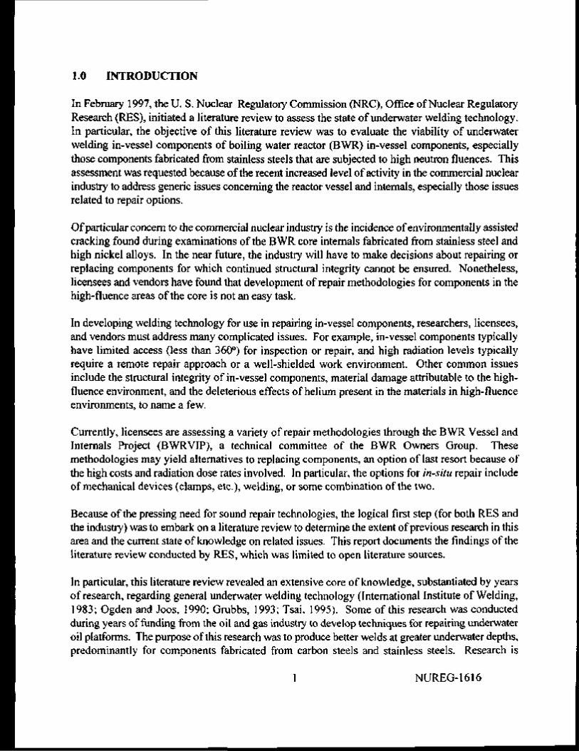
In February 1997, the U. S. Nuclear Regulatory Commission (NRC), Office of Nuclear Regulatory Research (RES), initiated a literature review to assess the state of underwater welding technology. In particular, the objective of this literature review was to evaluate the viability of underwater welding in-vessel components of boiling water reactor (BWR) in-vessel components, especially those components fabricated from stainless steels that are subjected to high neutron fluences. This assessment was requested because of the recent increased level of activity in the commercial nuclear industry to address generic issues concerning the reactor vessel and internals, especially those issues related to repair options.
Of particular concern to the commercial nuclear industry is the incidence of environmentally assisted cracking found during examinations of the BWR core internals fabricated from stainless steel and high nickel alloys. In the near future, the industry will have to make decisions about repairing or replacing components for which continued structural integrity cannot be ensured. Nonetheless, licensees and vendors have found that development of repair methodologies for components in the high-fluence areas of the core is not an easy task.
In developing welding technology for use in repairing in-vessel components, researchers, licensees, and vendors must address many complicated issues. For example, in-vessel components typically have limited access (less than 360°) for inspection or repair, and high radiation levels typically require a remote repair approach or a well-shielded work environment. Other common issues include the structural integrity of in-vessel components, material damage attributable to the high-fluence environment, and the deleterious effects of helium present in the materials in high-fluence environments, to name a few.
Currently, licensees are assessing a variety of repair methodologies through the BWR Vessel and Internals Project (BWRVIP), a technical committee of the BWR Owners Group. These methodologies may yield alternatives to replacing components, an option of last resort because of the high costs and radiation dose rates involved. In particular, the options for in-situ repair include of mechanical devices (clamps, etc.), welding, or some combination of the two.
Because of the pressing need for sound repair technologies, the logical first step (for both RES and the industry) was to embark on a literature review to determine the extent of previous research in this area and the current state of knowledge on related issues. This report documents the findings of the literature review conducted by RES, which was limited to open literature sources.
In particular, this literature review revealed an extensive core of knowledge, substantiated by years of research, regarding general underwater welding technology (International Institute of Welding, 1983; Ogden and Joos, 1990; Grubbs, 1993; Tsai, 1995). Some of this research was conducted during years of funding from the oil and gas industry to develop techniques for repairing underwater oil platforms. The purpose of this research was to produce better welds at greater underwater depths, predominantly for components fabricated from carbon steels and stainless steels. Research is
1 NUREG-1616

ongoing in this area at the Navy Joining Center, Massachusetts Institute of Technology (MIT) Ocean Engineering Department, E. O. Paton Electric Welding Institute, Sea Grant Program at Ohio State University, Edison Welding Institute, and The Welding Institute (TWI).
By contrast, this literature review revealed that substantially less research has been performed in the area of underwater welding in commercial reactor in-vessel environments. In practice, the weld repair in reactor in-vessel environments is restricted by limited access to the component to be welded, high radiation levels around the component, and complications associated with radiation damage to the component (Shah and MacDonald, 1993). In addition, this literature review revealed that most of the applicable literature regarding commercial nuclear plants conveys anecdotal experience involving emergent outage repairs in low-fluence areas inside the reactor vessel (as opposed to carefully controlled experimental work) (Jenco, 1990). Because of the scarcity of data pertaining to welding highly irradiated materials in an underwater environment, RES expanded the literature search to include a second base of applicable experience drawn from reactor tank repairs in a plant at the Department of Energy (DOE) Savannah River Site (SRS). In particular, failures of reactor tanks in service at the SRS led to the development of welding techniques that would work for repair welds in high-fluence environments; however, the reactor tank repairs at the SRS did not involve the complicating factor of underwater welding.
In addition, the RES drew a third base; of experience from the fusion reactor international research program, which yielded substantial weeding research involving tritium-doped materials that mimic helium entrapment effects without the damage normally associated with irradiated materials. Most fusion research efforts have focused on trying out various techniques for producing successful welds in these surrogate high-fluence materials without having the constraints of working with highly irradiated material. Like the SRS research, however, this research has been performed under dry welding conditions, not underwater. Together, these three sources of research data and experience provide a comprehensive picture of the problems associated with welding highly irradiated materials. They also suggest a variety of possible solutions to the problems.
Recently, for example, researchers in the Netherlands, United States, and Japan have conducted limited research involving the welding of irradiated materials, and future plans for the fusion community include more extensive research of this type. In addition, research into welding stainless steels exposed to high fluence levels has shown some promise as a result of altering the heat input into the weld and applying a compressive stress during the welding operation. Current research funded by the DOE Fusion Program is focused on refining the techniques that produce acceptable welds in the desired ranges of fluence. Although this research has been performed exclusively with dry welds, it proves relevant as a comprehensive examination of possible techniques that can be applied to welding highly irradiated materials.
To date, the published accounts show great promise for underwater weld repairs performed in low fluence in-vessel environments of commercial nuclear plants. In particular, successful underwater weld repairs have been made on austenitic stainless steel components with high-quality welds that have passed inspection during subsequent outages at Susquehanna Units 1 and 2, Peach Bottom Unit
NUREG-1616 2
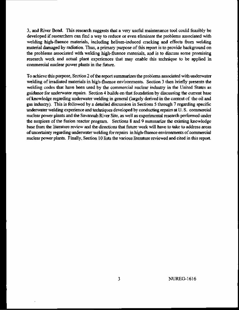
3, and River Bend. This research suggests that a very useful maintenance tool could feasibly be developed if researchers can find a way to reduce or even eliminate the problems associated with welding high-fluence materials, including helium-induced cracking and effects from welding material damaged by radiation. Thus, a primary purpose of this report is to provide background on the problems associated with welding high-fluence materials, and is to discuss some promising research work and actual plant experiences that may enable this technique to be applied in commercial nuclear power plants in the future.
To achieve this purpose, Section 2 of the report summarizes the problems associated with underwater welding of irradiated materials in high-fluence environments. Section 3 then briefly presents the welding codes that have been used by the commercial nuclear industry in the United States as guidance for underwater repairs. Section 4 builds on that foundation by discussing the current base of knowledge regarding underwater welding in general (largely derived in the context of the oil and gas industry). This is followed by a detailed discussion in Sections 5 through 7 regarding specific underwater welding experience and techniques developed by conducting repairs at U. S. commercial nuclear power plants and the Savannah River Site, as well as experimental research performed under the auspices of the fusion reactor program. Sections 8 and 9 summarize the existing knowledge base from the literature review and the directions that future work will have to take to address areas of uncertainty regarding underwater welding for repairs in high-fluence environments of commercial nuclear power plants. Finally, Section 10 lists the various literature reviewed and cited in this report.
3 NUREG-1616

2. PROBLEMS ASSOCIATED WITH WELDING IRRADIATED MATERIAL IN HIGH-FLUENCE ENVIRONMENTS
The literature reviewed in this study includes extensive discussion of two problems specific to welding highly irradiated materials. Specifically, these problems include cracking during the welding process as a result of helium entrapment in the material and cracking attributable to irradiation-damaged microstructure in the components. In an effort to understand the fundamental mechanisms and propose solutions to the problems associated with helium entrapment, a significant portion of the fusion program research has focused on welding tritium-doped materials, thereby simulating helium entrapment in the absence of the damage normally associated with irradiated materials.
As the following equations indicate, helium is formed by neutron reactions with alloy constituents, primarily boron and nickel (Goods and Karfs, 1991):
,0B + n -> 7Li + 4He
58Ni + n -> 59Ni + Y
59Ni + n -► 56Fe + 4He
Helium tends to have a low solubility in metals, and forms small clusters with diameters on the order of a few tenths of a nanometer at low temperatures, < 200°C (< 392°F), and 2 to 10 nanometers at high temperatures, 200°C to 600°C (392°F to 1112°F). Goods and Karfs (1991) have concluded that:
"Preferred nucleation sites for this helium-induced damage are lattice inhomogeneities such as radiation-induced defects, precipitate interfaces, dislocations, and most importantly, grain boundaries. At elevated temperatures, these clusters and bubbles can grow very rapidly and under applied stress can severely weaken grain boundaries. Because conventional, deep penetration, fusion welding processes produce high stresses (above the yield strength) as well as high temperatures (above the melting point), entrapped helium can severely affect the weldability and postweld properties of irradiated materials. The severity of the observed effects is thought to be dominated by helium content and by the extent and magnitude of the temperature and stress fields that prevail near the fusion line during welding."
By contrast, the "tritium trick" technique of implanting helium in the material by tritium charging (American Society for Testing and Materials, 1983), yields profoundly different levels of cracking after the material is subjected to the welding process when compared to materials that have been irradiated (Kanne et al., 1995). Kanne et al. (1995) has explained this phenomenon in terms of the preferential locations of the alloy constituents before transmutation and the nature of the transmutation products in the microstructure. (Irradiation of the material results in transmutation of certain elements such as boron or nickel, but tritium charging only implants helium in the material.) Since boron is often present in steels as an impurity, the helium produced from that
NUREG-1616 4
element is expected to form preferentially at the grain boundaries. Nickel, however, is present throughout the matrix, so its helium transmutation product is also distributed throughout the matrix. The presence of lithium as a transmutation product may also be detrimental to the welding process, and researchers suspect some difficult-to-measure contribution to the enhanced cracking during the welding of irradiated materials as a result of the radiation-induced damage to the metal matrix. The material exhibits this radiation-induced damage in the form of dislocation loops, dislocation networks, and voids (Lin and Chin, 1991b).
The available literature contains numerous instances in which helium-induced cracking occurred during the welding of irradiated materials (Hall et al, 1978; Atkin, 1981; Kanne et al, 1995; Robinson, 1988; Goods and Karfs, 1991; Lin and Chin, 1991a; Van Osch et al, 1994; Fabritsiev and Van der Laan, 1996; and Watanabe et al, 1996). However, these reports lack consensus regarding the absolute minimum level of helium that induces cracking during welding operations. This confusion results from the complexity and synergistic effects of the variables involved, including the base material, weld heat input, degree of radiation damage to the material, temperature of the material, residual stresses in the material, material microstructure, and so forth. In general, the most limiting helium values reported in the literature are in the range of 1 to 2 atomic parts per million (appm).
Although techniques exist for measuring the amount of helium present in a material in a laboratory environment, it is far more complex and expensive to determine (or predict) the amount of helium present in in-vessel materials that have not been removed from service. Consequently, researchers, licensees, and vendors generally predict the amount of helium in the reactor in-vessel materials using flux mapping techniques, retrospective dosimetry techniques, or similar calculated approaches, rather than directly measuring the content. Because of the imprecision inherent in estimating neutron flux from one location to another in the vessel, the calculations entail some degree of inherent error that is difficult to quantify.
One interesting exception is documented in a Japanese patent record, which describes an invention consisting of a laser beam mechanism and a mass analyzer to measure the atoms generated from laser irradiation of the material, thereby determining in-situ the amount of helium in the material (Fukutani, 1995). However, the literature does not state whether this device is presently being used in the nuclear industry in Japan, nor does it substantiate the reliability of such measurements.
5 NUREG-1616

3. WELDING CODES USED FOR UNDERWATER WELD REPAIR
In many environments, licensees and vendors have performed underwater welding according to American Welding Society (AWS) specification D3.6, "Specification for Underwater Welding," issued in 1983. This specification discusses welding variables, as well as associated procedures and welder qualification requirements. The specification primarily related to underwater welding of carbon and low-alloy steels common to offshore oil structures (O'Sullivan, 1988). In 1989, the original version of the specification was superseded by the American National Standards Institute (ANSI)/AWS D3.6. The latest edition of the standard is AWS D3.6-93. The underwater weld repairs in commercial nuclear power plants cited in the literature were all performed in accordance with either the original specification, AWS D3.6, or the later specification, ANSI/AWS D3.6.
According to O'Sullivan (1988), weld repairs in nuclear power plants are customarily performed according to the requirements of American Society of Mechanical Engineers (ASME) Boiler and Pressure Vessel (B&PV) Code, Sections IX and XI; however, the B&PV Code does not address the wet environment, submergence depth, and other pertinent variables. Also, the steam dryer (the component frequently mentioned in the open literature about repairs at Susquehanna), was not originally fabricated to the ASME B&PV Code or any other standard code or specification. By the time the River Bend Station was formulating repair strategies for a damaged feedwater sparger pipe, the industry had accepted the philosophy that ASME Section IX would be used for "position", and AWS D3.6 would be used for "depth range" (Mahan, 1990). Then, in 1989, the Electric Power Research Institute (EPRI) Non-Destructive Examination Center (NDEC) reviewed the Type 308L stainless steel weld deposits that were currently considered acceptable for most types of repairs in accordance with ANSI/AWS D3.6. As a result of that review, the NDEC determined that the welds would not be acceptable for ASME Code repairs (Findlan et al., 1992). Consequently, in 1989, EPRI initiated a research program to develop weldments that would qualify under Section IX of the ASME B&PV Code.
To further clarify the application of ASME Sections IX and XI for underwater welding, the ASME drafted Code Case N-516, which was approved on August 9, 1993, under ASME Section XI, Division 1. That Code Case cited ANSI/A WS D3.6 as a general requirement for underwater welding, and also specified requirements for procedure qualification, performance qualification, filler metal qualification, confirmation welds, and weld examination.
Just recently, the NRC has given conditional acceptance to Code Case N-516 (NRC, 1997). This acceptance is conditional because of the problems that have been noted in welding materials subjected to a high-fluence environment, and because Code Case N-516 fails to recognize the condition of the material to be welded. Therefore, to ensure that the welder has used adequate crack prevention measures when welding highly irradiated Class 1 materials, the conditional acceptance criteria require a demonstration of the weld technique using a material subjected to a similar neutron fluence in a weld-mockup.
NUREG-1616 6

4. UNDERWATER WELDING: GENERAL DISCUSSION
C.E. "Whitey" Grubbs wrote an exhaustive article about the "state-of-the-art" of underwater welding, which he submitted to the 12th International Conference On Offshore Mechanics and Arctic Engineering, as well as the 1994 Underwater Intervention Conference (Grubbs, 1993 and 1994). Since that time, the underwater welding technology has matured, with many organizations funding current research into optimized techniques and equipment (Tsai, 1995). Further background regarding the history of underwater welding and the development of specific techniques and electrodes appears in numerous comprehensive articles (Ogden and Joos, 1990; and Tsai, 1995) and conference proceedings (International Institute of Welding, 1983; American Welding Society, 1991; Underwater Intervention '94 Conference Committee, 1994). In his review, Grubbs (1993 and 1994) states that wet welding was used as early as 1917 to stop leaks from the seams and rivets in ship hulls, but these were not structural welds. Documented reports of underwater structural welds by skilled welders were first published around 1970, and a considerable number of repairs were performed in offshore structures, subsea pipelines, and dock and harbor facilities in the subsequent years. By 1985, welders and procedures were being qualified to a depth of 100 meters (328 ft).
Grubbs also discussed the many problems specific to underwater welding, including the rapid cooling resulting from the infinite heat sink represented by the surrounding water, the hydrogen enriched gaseous envelope surrounding the weld pool, and the reduction of manganese and silicon as well as the increase in carbon and oxygen associated with the increased hyperbaric pressure. These problems can lead to poor weld quality. However, for the special case of welding austenitic stainless steel using austenitic stainless steel electrodes, Grubbs stated that welders have made underwater weldments that are metallurgically superior in some respects to similar welds made above water. He further noted that 40 or more such underwater weld repairs have been made in nuclear power plants since 1980, mostly using Type 316L austenitic stainless steel welding electrodes to weld Type 304 austenitic stainless steel base metal. In addition, Grubbs stated that austenitic stainless steel resists transformation into martensite, so the weldment is essentially rapid-quench-annealed during the welding process and thereby minimizes heat-affected zone (HAZ) sensitization. Although other materials may not be as ideally suited for underwater welding, adjustment of weld parameters and electrode materials has provided good-quality welds that approach the quality of dry welds for the same material.
It is interesting to note that although "wet" underwater welding was the technique chosen for the commercial nuclear plant repairs, it is only one of several underwater welding techniques available to the welder. According to White et al. (1997), there are six general categories of underwater welding:
1) In wet welding, water separates the workpiece from the torch.
2) Dry-spot welding uses a slightly pressurized enclosure to surround the weld pool and arc volume, in order to keep out the intervening water.
7 NUREG-1616

3) Dry-box welding uses a box that encloses the head and shoulders of the welder, as well as the weld area.
4) In habitat welding, the weld areas are isolated from the water, and the welder does not have to wear diving equipment.
5) Chamber welding uses a chamber that is maintained at a pressure of 101 kPa (1 atm) to keep the water out.
6) Remote welding does not require continuous welder participation during the joining operation (that is, the procedure relies on automatic or robotic welding systems).
Of these six, welding technique 1 has been the preferred choice of licensees when making repairs to in-vessel reactor components because the surrounding water affords additional radiation shielding. Nonetheless, welding techniques 2 through 5 offer considerable advantages because the weld is essentially fabricated in a dry environment. (This is especially important for carbon steel welds, since underwater wet welds in carbon steels can suffer from a rapid quenching effect and a susceptibility to hydrogen embrittlement, which can lead to porosity, slag entrapment, lack of fusion, and lack of penetration in the weld.) However, application of techniques 2 through 5 can be limited by the accessibility of the weld to effect the repair, and some weld areas simply cannot accommodate an enclosure around the weld area. The relative ease of setup and execution also makes technique 1 attractive, especially for the special case of welding internal BWR vessel components, as long as the weld quality will meet the requirements of ASME Section IX.
NUREG-1616 8

5. IN-VESSEL WELD REPAIRS AT U.S. COMMERCIAL NUCLEAR POWER PLANTS
During the course of this literature review, the RES identified detailed accounts of weld repairs performed at Susquehanna Units 1 and 2, Peach Bottom Atomic Power Station Unit 3, and River Bend Station (O'Sullivan, 1988 and 1990; Mahan, 1990; The Nuclear Professional, 1990; and Reynolds et al, 1991). (Table 1 summarizes the available information about the weld repairs.) The reader should note, however, that the weld locations addressed in the literature were all in low fluence areas inside the reactor vessel.
Table 1 In-Vessel Weld Repairs in U S Commercial Nuclear Power Plants
Date
1984
1987
1988
1989
1989
1988
1989
Plant
Susquehanna Unitl
Susquehanna Unitl
Susquehanna Unit 2
Susquehanna Unitl
Susquehanna Unit 2
Peach Bottom Unit 3
River Bend Station
Repair
Steam Dryer Hood
Steam Dryer Hood
Feedwater Sparger
Steam Dryer Drain Channel
Steam Dryer Tie-Rod Capture Plates
Steam Dryer Drain Channels Alignment/ Seismic I ug
Feedwater Sparger Pipe
Mat'l
304 SS
304 SS
Aust SS
304 SS
304 SS
304 SS
316L
Weld Depth
N/A (Dry weld)
1 8 to 4 3 m (6toI4ft)
13m (43 ft)
5 m (17 ft)
1 8 to 4 3 m (6 to 14 ft)
4 to 6 m (13 to 23 ft)
13 m (43 ft)
Weld Technique
GTAW
SMAW
SMAW
SMAW
SMAW
SMAW
SMAW
Electrode
Dry ER308L Filler Metal
Low-Carbon 316L w/propnetary waterproof coating
316L Filler Metal w/Al waterproof coating
316L Filler Metal w/Al waterproof coating
316L Filler Metal w/Al waterproof coating
1 ow-Carbon 3I6L w/propnetary waterproof coating
I ow-C arbon 3161 w/propnetary waterproof coating
Contractor Name
Utility
Global Divers & Contractors
Utility
Utility
Utility
GE Nuclear and Global Divers & Contractors
Global Divers & Contractors
The RES found it difficult to ascertain the scope of repairs in the commercial nuclear industry solely on the basis of an open literature search. One report made reference to similar underwater repairs by Georgia Power Company (Reynolds et al, 1991). Jim O'Sullivan, of Pennsylvania Power and Light (PP&L), stated that at least a dozen plants have made, or plan to make, similar underwater weld repairs, both domestically and abroad (The Nuclear Professional, 1990). He also mentioned that the Japanese have shown interest in, and become converted to the idea of underwater welding. This is supported by a Japanese patent application in the open literature, which describes a device for measuring in-situ helium in reactor structural components to assess the feasibility of welding in-vessel structural components (Fukutani, 1995).
9 NUREG-1616

Allegedly, diver/welders using a shielded metal arc welding (SMAW) process, have manually performed additional underwater weld repairs on manway covers and jet pump hold-down beams; however, the details of the repairs are not readily gleaned from the open literature (Findlan et al, 1992). According to Findlan et al., research has been underway at the EPRI NDEC since 1989, to study techniques that can successfully be applied for weld repairs in high-fluence in-vessel areas of commercial nuclear power plants. Because of accessibility concerns for divers in the lower portions of the reactor vessel, where components generally are not removed for repair and radiation levels are prohibitively high, automated remote underwater wet welding processes are desirable.
Initially, the EPRI built on the base of available knowledge about underwater welding, most of which was initially developed for offshore applications (Smith and Childs, 1991). Manual SMAW was the most common process, and defects such as porosity and lack-of-fusion plagued much of the underwater welds. The developmenl work resulted in some improvement of the SMAW techniques, including the use of pulsed welding arcs with commercially available electrodes to maintain a lower average current, thereby reducing weld spatter and improving penetration.
The EPRI also initiated the development of automated weld processes for applications in the lower portions of the reactor vessel, and performed a literature survey to identify past uses of remote underwater welding (Findlan et al., 1992). The results of the literature survey indicated that a water-free, dry habitat was used in a majority of the cases. On the basis of the results from the literature survey, a vendor survey, and past experience, the EPRI selected flux core arc welding (FCAW) as the topic of further study. This study revealed that better quality welds were performed using commercially available stainless steel self-shielded wires (compared to welds using gas-shielded wires). With the self-shielded wires, a gas bubble was created around the molten weld bead and the bubble developed into an easily removed slag deposit. The finished welds were quite sensitive to the welding parameters, including torch angles, electrical polarity, wire size and type, and voltage. The EPRI further developed this technique for a member utility, in order to add weight to a jet pump riser bracket to change the vibrational harmonics which could otherwise crack the bracket weld. The process was successfully demonstrated under water with porosity and slag-free welds in non-irradiated material, but the utility did not need to make the repair during the outage. No further information about the use of this technique appeared in the literature.
The following sections summarize the particulars of each nuclear plant weld repair documented in the open literature.
5.1 In-Vessel Weld Repairs at Susquehanna
In total, the open literature documented five in-vessel weld repairs at PP&L's Susquehanna Steam Electric Station, Units 1 and 2. Of these five, welders at Unit 1 performed the first weld repair above water, after preparing the weld under water to reduce exposure. The next time a weld repair was required for the steam dryer, the exposure rates were prohibitively high and welders performed repairs under water. Welders also performed the three subsequent repairs to the steam dryer and
NUREG-1616 10

feedwater sparger under water. Sections 5.1.1 through 5.1.5 discuss the details of the individual repairs, and Section 5.1.6 summarizes the lessons learned from these repairs.
5.1.1 First Repair
In-service visual inspection of Susquehanna Unit 1 during the first refueling outage in 1984 revealed a crack in the steam dryer (O'Sullivan, 1988). This crack was approximately 168 cm (66 in.) in length, and was located in the weld metal and along the fusion zone of the weld between the hood and end panel of the steam dryer. This weld failure was subsequently identified as resulting from fatigue. The welder therefore prepared the failed region for weld repair under water, but performed the repair dry using manual gas-tungsten arc welding (GTAW) with ER308L filler metal. The repair consisted of re-welding the joint, as well as welding a Type 304L plate over the joint to provide additional reinforcement against cyclic loading.
5.1.2 Second Repair
During the third refueling outage (October 1987), inspection personnel discovered a similar crack in another weld joint. This crack was 137 cm (54 in.) in length, and was also identified as resulting from fatigue. For this repair, the elevated steam dryer radiation levels made dry welding undesirable, so the licensee considered underwater weld repair to be the preferable alternative. At the time, however, the industry had little experience in welding stainless steel under water, since most of the underwater welding up to that time involved carbon and low-alloy steels common to offshore oil structures. PP&L therefore selected a contractor, Global Divers and Contractors, Inc. of Port of Iberia, Louisiana, because the company had a considerable amount of underwater welding experience, hyperbaric test facilities for procedure and welder qualification, and involvement in the AWS subcommittee on underwater welding to develop underwater welding techniques to repair the steam dryer.
Global Divers and Contractors, Inc. developed procedures and qualifications for SMAW with direct current on the basis of AWS D3.6 (American Welding Society, 1983) Type B welds on A240 Type 304 and Type 304L stainless steels. The contractor also specified low-carbon stainless steel electrodes with a minimum ferrite number of 8.0, as well as qualification testing standards including weld position, visual acceptance criteria, radiography requirements, metallography requirements, chemical analysis requirements, as-welded ferrite determination, and tensile and shear mechanical test requirements for single V-groove butt joints (requiring 65% minimum penetration) and fillet welds. The final procedure that the welders used for qualification specified 75% partial penetration 3G groove welds on 0.32-cm and 0.64-cm (Vs-in. and Vi-in.) groove welds, with performance testing of two each root and face bends as well as three macro specimens for each thickness. Divers prepared the steam dryer surface with a water grinder, and used a pneumatic chipping gun for interpass and final cleaning. The final fit-up resulted in a 90-degree V-groove, and the welding sequence consisted of placing 10.2-cm (4-in.) long tacks on approximately 30.6-cm (12-in.) centers beginning near the bottom, followed by the root and cover pass. Divers then welded reinforcing
11 NUREG-1616

plates to each of the three corners. Inspectors performed final acceptance by a remote visual (video) examination, and all of the welds passed. In addition, the welds were re-inspected during the fourth refueling outage in Spring 1989, and the welds were still deemed intact (O'Sullivan, 1990).
5.1.3 Third Repair
During the second refueling outage in May 1988, misalignment of the separator guide lugs and the vessel internal guide rods led to damage of the Unit 2 feedwater sparger (O'Sullivan, 1990). The damage resulted in a 3.8-cm (1/4-in.) long open split on the upper face of a nozzle on the feedwater sparger. The weld repair consisted of a welded overlay over the horizontal indentation in the nozzle, and a built-up closure patch applied to the vertically-oriented open split. The welders were qualified for groove-welding P-8 (austenitic) base metals, using 316L filler metal with an aluminum waterproof coating, between 0.32 and 0.95 cm (Vb-in. and 3/s-in.) thickness in horizontal and vertical positions at depths from 3 to 19 m (10 to 63 ft.). As before, inspectors performed final acceptance of the welds by remote visual (video) examination, and the welds passed. In addition, the welds were re-inspected at the next refueling outage (Fall 1989), and the repair welds were still deemed intact.
5.1.4 Fourth Repair
During remote video inspection of the steam dryer during the fourth refueling outage of Unit 1 (Spring 1989), inspectors discovered a 46-cm (18-in.) long fatigue crack in the horizontal fillet weld between the top of one drain channel and the dryer support ring, and the crack advanced about 7.6 cm (3 in.) into the 0.32-cm (Vs-in.) thick base metal of the drain channel (O'Sullivan, 1990). Divers therefore drilled a 2.54-cm (1-in.) hole into the lower end of the crack in the drain channel to prevent further crack propagation. The welder also used the sparger repair procedure cited in Section 5.1.3 to ensure welder qualification for overhead fillet (4F) welding of 0.32-cm to 1.27-cm (Vs-in. to '/2-in.) and thicker austenitic stainless steel base metal. In addition, the welder removed the cracked fillet weld, as well as some additional weld material at the end of the cracked weld, and restored the horizontal weld to the maximum size allowed by the configuration. Inspectors performed final weld acceptance by remote visual (video) inspection.
5.1.5 Fifth Repair
Inservice inspection during the Fall 1989 outage revealed a crack-like indication perpendicular to a vertical drain channel-to-skirt weld in the steam dryer (O'Sullivan, 1990), which prompted PP&L to devise a repair strategy for a possible crack. PP&L also had a plan for a contingency modification in which stainless steel capture plates would be welded over the openings of the steam dryer containing tie-rod end nuts which held the internal baffles during original dryer assembly. (This was a contingency modification because tie-rod end nut cracking had been discovered at other plants, although in-service inspection at Susquehanna had not revealed any indications of cracking in the end nuts.) Close visual inspection of the indication by a welder subsequently revealed that the indication was not a crack, so the wedding staff simply planned and executed the capture plate
NUREG-1616 12

installation. The welder qualification required single-pass fillet welds in the horizontal, vertical, and overhead positions (2F, 3F, and 4F).
5.1.6 Summary of Susquehanna Weld Repairs
Underwater weld repairs were successfully performed at Susquehanna, Units 1 and 2, and were documented carefully in the open literature. Jim O'Sullivan, Group Supervisor of Installation Engineering at Susquehanna (also the plant welding engineer for the period of the weld repairs) not only provided a detailed summary of the weld repairs, but also commented on the fine quality and integrity of the welds performed with this technique (O'Sullivan, 1990). He stated in the literature that a welder can achieve acceptable results from welding carbon steel under water, but can attain excellent results from welding under water with stainless steel (The Nuclear Professional, 1990).
5.2 In-Vessel Weld Repair at Peach Bottom Atomic Power Station Unit 3
During an outage at the Peach Bottom Atomic Power Station Unit 3, operated by the Philadelphia Electric Company (PECO), the steam dryer was damaged as a result of misalignment with the reactor guide pin during reinstallation inside the reactor (Reynolds et al., 1991). As a result, the steam dryer required repair of structural damage at the 0° and 180° azimuth, cracks at the welds at the base of the drain channels, and an alignment/seismic lug located at the 270° azimuth. PECO therefore contracted with General Electric (GE) Nuclear Energy and Global Divers and Contractors to plan and execute the necessary repairs. Welders were qualified for four different welding positions (2G, 3G, 2F, and 3F) on base metal thicknesses from 0.32-cm to 2.54-cm (Vfe-in. to 1-in.) at working depths from 4 to 6 m (13 to 23 feet). The welding procedure and qualifications were in accordance with AWS D3.6 - 83. The filler metal was an E316L SMAW electrode with a proprietary waterproof coating, and the base material of the steam dryer was SA240 Type 304 stainless steel. Qualification tests included ferrite determination, chemical examination, visual examination, radiography, tensile tests, fillet weld shears, root/face/side bend tests, and macroexamination. Weld areas were prepared by using a water-powered grinder or an arc water-gouge tool, and pre-fabricated assemblies (such as plates, a dryer skirt, a support ring, and a guide bracket) were welded into place. The welds were all inspected using underwater video cameras.
5.3 In-Vessel Weld Repair at River Bend Station
Inservice inspection at the River Bend Station (operated by Gulf States Utilities) revealed a damaged nozzle on the feedwater sparger pipe (Mahan, 1990). The sparger was constructed from 15.2-cm (6-in.) Schedule 80 SA312, Type 316L pipe, and specifically, the repair locations were 13 m (43 ft) under water, at approximately 3 m (10 ft) above the vessel's loaded core. Further inspection identified the cause of the damage as a misplaced scaffold knuckle clamp and revealed a second misplaced scaffold knuckle clamp in a separate sparger. In consultation with GE, the licensee decided that the header design would still perform its function with two less nozzles per sparger, so the licensee developed a repair technique to repair the sparger and eliminate the affected nozzles.
13 NUREG-1616

Gulf States Utilities then contracted with Global Divers and Contractors to assist with the repair. The contractor provided mock-up training at their hyperbaric welding and testing facility. The expected repair activities included cutting off the nozzle, cleaning the outer surface of the pipe, removing the scaffold clamp, preparing the hole and replacement plug, and welding the plug into place. Welders were qualified in accordance with AWS D3.6-83 for type "O" welds, so that ASME Section IX could be used for all essential variables not affected by the underwater environment. The welders were also specifically qualified in the 3G position on 0.95-cm (%-in.) groove welds with backing. In addition, because the contractors used this approach to qualify the welders for position under the ASME Code and depth range under the AWS D3.6 specification, the procedure was qualified for all positions and depths from 1.5 to 16 m (5 to 53 ft). The contractor also used a diver's workstation to shield the welders and to support a loose parts dam cloth positioned to capture any cutting dross, parts, or tools. An electrically driven positive-displacement water pump provided water power for the water grinder and arc-water gouging unit. The contractor preferred water-driven power tools over the pneumatic tools, because they eliminate the loss of visibility that otherwise results from excessive bubbles under water. In addition, the utility used video equipment, including fiber optics, TV monitors, and underwater cameras, to record the process and to inspect the final welds. According to the published account of the repair (Mahan, 1990), the process resulted in a good-quality, permanent repair of the sparger pipe.
NUREG-1616 14

6. WELD REPAIRS ON HIGH-FLUENCE MATERIALS AT THE DOE SAVANNAH RIVER SITE
Since the 1950's, the U.S. Department of Energy (DOE) has built and operated five production reactors at the Savannah River Site (SRS) to produce radioactive materials for national defense and peacetime applications. The reactors were unpressurized, operated at temperatures below the boiling point of water, and used heavy water as a moderator. One reactor had a unique design that incorporated a curved knuckle to join the reactor tank sidewall to the reactor tank bottom. The tank was fabricated from high carbon (-0.07%) Type 304 stainless steel, and the knuckle region was sensitized during fabrication and subsequently experienced stress corrosion cracking (SCC) during service. In 1968, welders used stainless steel patches to successfully repair the knuckle region, and these patches were welded to the tank walls using GTAW techniques (Maloney, 1969; Kanne, 1988). These weld repairs were made in air, not under water.
In 1984, the tank again began to leak, and SRS staff planned and executed weld repairs that were similar in scope to those performed in 1968 (Kanne et al, 1987; Kanne, 1988). Again, the weld repairs were made in air, not under water, and autogenous GTAW was used to install repair patches in the 105 R/h radiation field of the reactor. During this process, SRS staff noted extensive cracking in the HAZ of the tank side of the welds, but the patch (new metal) side of the welds was free of cracks. Extensive analysis eliminated many potential causes of the cracking, including incomplete fusion to the tank wall, hydrogen embrittlement, pre-existing undetected intergranular stress corrosion cracking (IGSCC), intergranular attacks from pickling during fabrication, and radiation-induced segregation. SRS welding staff suspected helium induced cracking because of the known effects of helium increasing low-temperature strength and decreasing ductility. The staff estimated that the reactor tank walls contained approximately 3 appm of helium, and calculated fluences to be 1 x 10²¹ n/cm2 thermal and 1 x 10'6 n/cm2 fast (Kanne, 1993a). In addition, staff at Sandia National Laboratory purely computed fast fluences (greater than 0.1 MeV) and thermal values were based on the measured helium content with derived corrections for boron contributions and extrapolations to the surface. (High stresses and high temperatures introduced by welding were thought to contribute to the propensity for cracking.)
Before this observation, only a few observations of cracking or porosity had been attributed to welding of materials with entrapped helium (Hall et al., 1978; Atkin, 1982; Schiller et al., 1987; Clark et al., 1986). Consequently, SRS welding staff performed tests to confirm their suspicions about the role of helium in the HAZ cracking (Kanne et al, 1993b). Specifically, the staff performed GTAW test welds identical to the tank repairs on tritium-doped 304L plates with preexisting GTAW (before the tritium doping). In addition, because a concentration gradient of helium was present on the plates as a result the tritium charging process, the staff was able to make observations for a high-helium weld environment and a weld environment relatively free of helium on the same plate. As a result, the staff observed cracking only in the HAZ region of the tests welds in the areas that contained helium, and the preexisting weld exhibited no cracks. Low heat input welds with base metal melting and spot GTAW also produced cracking, but resistance welds or a low heat GTAW pass with no base metal melting caused no cracking (Kanne, 1988).
15 NUREG-1616

These findings led to a comprehensive research effort to develop welding techniques that would reduce the helium-induced cracking associated with the welding of irradiated materials. (Table 2 summarizes the combination of repairs and research at the SRS.) During this research, the welding staff considered at least 30 different processes, but concentrated on the gas metal arc (GMA) overlay weld technique utilizing very low heat inputs, because this technique showed the greatest initial promise (Franco-Ferreira and Kanne, 1992; Kanne et al., 1991 and 1994; Kanne 1993a and 1995; andPerra, 1990).
Table 2. Weld Repairs and Research at the DOE Savannah River Site
Date
1968
1984
1984 to 1994
Item Welded
Tank knuckle region
Tank knuckle region
Specimens from tank wall
Material
304 SS
304 SS
304 SS
Description
GTAW repair of tank with SS patches; no problems identified with repair
GTAW repair of tank with SS patches attempted; resulted in extensive HAZ cracking
Reduced amount of cracking in HAZ observed for GMA overlay technique; postweld crack lengths in irradiated materials measured 28 times greater than for tritium-doped material
Studies showed that the heat input to the irradiated material must be minimized, since growth of the helium bubbles (resulting from a diffusion creep mechanism) from their initial nanometer size to approximately 1 micron in diameter occurred at temperatures above 500°C (932°F) (Franco-Ferreira and Kanne, 1992; and Kanne et al. 1995). The SRS welding staff therefore developed a weld overlay technique utilizing Type 308 filler wire to produce a weld weave 2.6-cm (1-in.) wide and 0.9-mm (0.035-in) thick (Kanne, 1993a). The extent of the weld penetration into the base metal was only 0.08-mm (0.003-in), which reduced the size of the HAZ. Welders performed test welds on 15-cm (5.9 in.) discs cut from the wall of a SRS reactor tank, with measured helium concentrations of 10.4 appm on the inside surface and 5.0 appm on the outside surface. No large surface cracks were visible in the HAZ around the edge of a weld bead, either by dye penetrant or metallographic analysis. However, approximately twice the amount of underbead cracking was discovered for the 10.4 appm region as for the 5.0 appm region. In addition, some minor cracking was observed in the HAZ, but far less than that observed for conventional penetration welds.
The SRS staff also used the weld overlay technique on tritium charged specimens, and compared the microstructural features from these welds to those found as a result of conventional weld techniques by Sandia National Laboratories (Goods and Karfs, 1991; and Perra, 1990). Cracking in the HAZ
NUREG-1616 16

was found for all of the weld techniques (even the low heat input weld overlays), and the degree of cracking positively correlated to the helium concentration and heat input.
The SRS welding staff directly compared the post-weld crack lengths measured in materials subject to helium implantation by tritium decay and irradiated materials. In comparison to the overlay test welds performed on tritium-charged and aged materials, the measured crack lengths from overlay welds on the irradiated material were up to 28 times greater. Kanne et al. (1993) concluded that the low heat input weld overlay technique showed promise, but needed additional development work on irradiated materials. Unfortunately, the last tritium production reactor at SRS was placed in cold-standby in 1993, and finally shut down permanently in 1996, so further development under the auspices of this welding research and development (R&D) program was suspended.
17 NUREG-1616

7. INTERNATIONAL FUSION PROGRAM RESEARCH ON WELDING OF HIGHLY IRRADIATED MATERIALS
The DOE-sponsored fusion reactor research program has provided an especially active area of welding research into the problems, associated with helium-induced cracking. Because of the expected severity of the materials environment, research has been ongoing for a number of years, both domestically and internationally, to develop repair techniques for components that are degraded by exposure to high fluences in future fusion reactors. In particular, the available literature includes extensive reports of collaborative efforts between the research staffs at Sandia National Laboratories, Oak Ridge National Laboratory, and Auburn University.
Table 3 summarizes the significant fusion program research in the open literature regarding welding of highly irradiated materials, and Table 4 identifies the materials used in the DOE-sponsored fusion research program. Lin et al. (1989) noted that intergranular cracking was found in the HAZ of welded Type 316 stainless steel doped to 27 and 105 appm helium. The weld technique was GTAW with the plates under full restraint to simulate structural restraint. Lin et al. (1990) continued this research by observing the effects of changing the welding parameters and helium concentrations. They tried both full and partial (30 to 50% depth) penetration GTAW welds under full constraint for materials doped with helium to conceintrations of 0.18, 2.5,27, 105, and 256 appm. They noted that for the full-penetration welds, intergranular HAZ cracking was observed for ^2.5 appm helium, and no cracking was observed for 0.18 appm helium. For the partial-penetration welds, intergranular HAZ cracking was observed for specimens with 105 appm helium.
Lin and Chin (1991a) continued this research by observing the effects that modifying the alloy metallurgical condition had on GTAW welding of highly irradiated materials under full constraint. They used Type 316 stainless steel in the solution-annealed (SA) condition, with a 20% cold work (CW) condition, and a titanium modified condition referred to as the "primary candidate alloy" (PCA). Again, the materials were eloped to helium levels of 0.18 to 256 appm. Lin and Chin observed that for the 316SA material, severe, continuous HAZ cracking occurred for >2.5 appm helium, but the material was free of weld defects at 0.18 appm helium. They also observed that for the 20% CW material, cracking occurred in the HAZ at >1.9 appm helium, but was less weld cracking occurred at 1.6 appm helium in the PCA material.
In collaboration with Wang, Lin et al. attempted a different technique to control the helium-induced cracking during welding (Wang et al., 1992). They used a hydraulic plate fixture to apply a controlled compressive stress perpendicular to the weld path (55 MPa (8 ksi), 25% of room temperature yield stress) during the GTAW process under full constraint. No visible cracks were observed in the HAZ for Type 316 stainless steel doped to 256 appm helium. They continued this research by varying the magnitude of compressive stress and levels of helium in the material, in order to determine the minimum level of stress necessary to mitigate helium-induced cracking (Wang et al., 1993, 1995). They used the GTAW process to perform full-penetration welds on fully constrained plates doped with 0.7,1.5, 5.2, and 10 appm helium, subjected to compressive stresses between 55 and 165 MPa (8 and 24 ksi). They observed no cracking for the material doped to 5.2
NUREG-1616 18

Table 3. International Fusion Program Research on Welding of Highly Irradiated Materials
Researcher/ Year
Lin et al., (1989)
Lin etal, (1990)
Lin and Chin, (1991)
Wang etal., (1992)
Wang etal, (1995)
Wang etal., (1996)
Goods and Karfs, (1991)
Goods and Yang, (1992)
Mat'l
316
316
316 SA 316 20%CW 316 PCA
316
316
316 20%CW PCA25%CW HT-9
304
304
Weld Technique
Autogenous GTAW -full penetration under full constraint
GTAW-full and partial penetration (30 to 50% depth) under full constraint
GTAW-full penetration under full constraint
GTAW-full penetration
GTAW-full penetration under full constraint
GTAW-full penetration
Conventional GMAW: deen penetration GMAW overlay: shallow penetration
GMAW overlays: shallow penetration
Method of He Production
Doped by "tritium trick"
Doped by "tritium trick"
Doped by "tritium trick"
Doped by "tritium trick"
Doped by "tritium trick"
Irradiated in ORR
Doped by "tritium trick"
Doped by "tritium trick"
He Levels
27 and 105 appm
0.18,2.5,27,105, and 256 appm
0.18 to 256 appm
256 appm
0.7, 1.5, 5.2, and 10 appm
316: 75 appm PCA: 86 appm HT-9: 2 appm
2.7 and 85.0 appm
22.5 and 85.0 appm
Fluence
N/A
N/A
N/A
N/A
N/A
target fluence 7dpa
N/A
N/A
Results
IG HAZ cracking at both He levels
Full penetration welds: IG HAZ crackine for ^2.5 appm He, no cracking observed for 0.18 appm He Partial penetration welds: IG HAZ crackine for 105 appm He specimens
316: 0.18 appm free of weld defects, severe, continuous HAZ for >2.5 appm 20% CW: crackine in HAZ >1.9 appm PCA: less weld cracking at 1.6 appm
Hydraulic plate fixture used to apply controlled compressive stress perpendicular to the weld path (25% of YS -at RT), no visible cracks in HAZ
Hydraulic plate fixture used to apply 55 to 165 MPa compressive stress; no cracking found for 5.2 appm He with fixture; no cracking found for 0.7 appm He w/out fixture
Stresses of 0,55,110, and 165 MPa applied perpendicular to weld direction; for 0 stress: crackine in 316 and PCA. no crackine in HT-9 for stresses >0: no crackine observed in welds
HAZ cracking in all specimens (significantly less in low heat input overlay welds)
Degree of cracking not significantly affected by the application of second overlays compared to single-pass welds

Table 3. Continued
9 Researcher/ Year
VanOsche/a/., (1994)
Fabrhsiev and Van der Laan,(1996)
Watanabeefa/., (1996)
Mat'l
316L-SPH (316L(N))
316L-SPH (316L(N))
316
Weld Technique
Laser welding Nd/YAG: low heat input
Automatic electron beam welding
Butt-welded TIG arc welds
Method of He Production
Irradiated in HFR
Implanted by cyclotron
Irradiated in JOYO
He Levels
7±2appm
50,100, 300, and 860 appm
3 to 9 appm
Fluence
upto0.6dpa
N/A
7to22dpa (1.6to4.6)xl0Mnm-2
( i 0.1 MeV)
Results
No surface cracks in HAZ or fusion zone found; metallographic sections showed some weld cracks and porosities, mainly in fusion zone; found surface cracks in welding of un-irradiated material also; author believes cracks resulted from insufficient control of laser weld parameters, not He
Microcracks were not found in the HAZ, nor in the weld of 316L (N) with 50-300 appm He; very small microcracks appear only in the welds of specimens w/860 appm He; microcracks appeared in the Crl6NillMo3Ti
HAZ cracking not observed just after welding, although observed after tensile testing; irradiated weld joint specimens fractured at the HAZ where plastic deformation was not large
to ©

Table 4. Composition of Materials Used in the Fusion Research Program
Elements
Al(wt%)
As(wt%)
B (wt%)
C(wt%)
Co(wt%)
Cr(wt%)
Cu(wt%)
Mn(wt%)
Mo(wt%)
N(wt%)
Nb(wt%)
Nb + Ta(wt%)
Ni(wt%)
0(wt%)
P(vrt%)
S(wt%)
Si(wt%)
Sn(wt%)
Sr(wt%)
Ta(wt%)
Ti(wt%)
V(wt%)
W(wt%)
Alloy Type 316
— —
(4 appm B)
0.06
0.3
17.4
0.3
1.7
2.1
0.06
<0.05
12.4
0.037
0.18
0.67
0.01
O.05
PCA
0.05
14.0
1.8
2.3
0.01
16.3
0.01
0.44
0.24
—
Alloy HT-9
<0.001
<0.001
0.21
0.017
11.99
0.05
0.50
0.93
0.005
0.018
0.43
0.005
0.011
0.004
0.18
0.002
<0.001
0.003
0.27
0.54
Alloy Type 304
0.073
18.22
1.39
8.28 .
0.023
0.016
0.52
—
— —
—
—
Alloy 316-SPH
0.0011
0.020
0.079
17.15
0.09
1.75
2.38
0.077
12.19
0.019
0.001
0.35
<0.001
—
—
—
Alloy 316 (Japan)
0.004
0.0001
0.05
0.31
16.80
0.25
1.72
2.18
0.0254
0.004
13.60
0.024
0.006
0.48
0.037

appm helium using the hydraulic compressive stress fixture, whereas the lower limit for no observed cracking was 0.7 appm helium without using the fixture.
Because this technique of using compressive stress during welding seemed promising, Wang et al. (1996) then tried the technique for Type 316 - 20% CW, PCA 25% CW, and HT-9 (ferritic steel heat-treated to a tempered martensite microstructure) that had been irradiated in the Oak Ridge Research Reactor (ORR) to a target fluence of 7 dpa. Because of the different concentrations of Ni and B in the material, the helium concentrations were different for each alloy (75 appm for 316, 86 appm for PCA, and 2 appm for HT-9). For tests with no applied compressive stress, no cracking was observed in the HT-9 material, but cracking was observed in the other two materials. For applied stresses of 55,110, and 165 MPa (8,16, and 24 ksi) applied perpendicular to the weld direction, no cracking was observed in the welds.
Concurrently at Sandia National Laboratories, Goods, Karfs, and Yang were evaluating weld overlay techniques to mitigate the helium-induced cracking caused by welding (Goods and Karfs, 1991; and Goods and Yang, 1992). The material they used was Type 304 stainless steel that was doped to 2.7 and 85 appm helium using the "tritium trick" method. Welding was performed using conventional GMAW (deep penetration) and GMAW overlay (shallow penetration), and significantly less HAZ cracking was observed for low heat input overlay welds. The effect of adding a second overlay pass as (compared to a single-pass weld) was evaluated for Type 304 stainless steel doped to 22.5 and 85.0 appm helium. It was observed that the degree of cracking was not significantly affected by the application of second overlays.
Van Osch et al. (1994) in the Netherlands also published results of mitigating techniques for welding highly irradiated material. Specifically, they used a Nd/YAG laser welding technique that provided a low heat input to the material. They also used a 316L-SPH alloy, irradiated to 0.6 dpa in the high-flux reactor (HFR) in Petten. This level of irradiation yielded a level of 7±2 appm helium in the material. The 316L-SPH alloy is a designation given to a 316L(N) alloy used in the Superphenix fast breeder reactor. As a result of this research, Van Osch et al. observed no surface cracks after the welding process, although metallographic sections showed some weld cracks and porosities (mainly in the fusion zone). Since they found surface cracks in the un-irradiated material, the researchers believed that the cracks were caused by insufficient control of laser weld parameters, and not necessarily by helium-induced cracking.
Fabritsiev et al. (1996) also performed welding research on the same material (316L-SPH) using automatic electron beam welding. In this research, helium was implanted into the material by cyclotron, at levels of 50, 100, 300, and 860 appm. (A cyclotron was used to incorporate defect generation into the pre-welded material, because defect generation is not associated with materials doped with helium from the "tritium trick" procedure.) Fabritsiev et al. did not observe microcracks in the HAZ or in the weld for the material with helium levels from 50 to 300 appm, and noted only very small microcracks in the welds of specimens with 860 appm helium.
NUREG-1616 22

Japanese researchers used yet another technique for welding irradiated Type 316 stainless steel. Watanabe et al. (1996) butt-welded, with tungsten inert gas (TIG) arc welds, 10% cold-worked Joyo Plant (an experimental fast reactor) wrapper tubes irradiated to 7 to 22 dpa, which resulted in a calculated 3 to 9 appm helium in the material. The tubes were irradiated at a fluence of (1.6 to 4.6) x 1026 nm"2 (Ei 0.1 MeV). Although HAZ cracking was not observed after welding, the irradiated weld joint specimens fractured at the HAZ during tensile testing after little plastic deformation.
23 NUREG-1616

8. DISCUSSION
Table 5 summarizes the various techniques that have been used for underwater welds in low-fluence areas of the reactor core, for welds involving highly irradiated materials in the fusion program, and for welds used on the DOE SRS reactor tank material. From the underwater welding experience in the nuclear plants, it is obvious that stainless steel can successfully be welded in low-fluence reactor core environments of BWRs. It also appears that reducing the heat input to the base metal can minimize or possibly eliminate helium-induced cracking during the weld process. However, it must be emphasized that there are no reports available in the open literature that describe successful attempts to weld highly irradiated components in situ in the in-vessel environment of a BWR. In the absence of documented welding efforts involving highly irradiated reactor in-vessel components, assumptions about the welding behavior must be surmised on the basis of relevant fusion research and DOE SRS reactor welding experience.
Many of the techniques discussed in this report seem promising in their ability to minimize the heat input to the weld, thereby reducing the size of the HAZ and minimizing helium bubble growth. The common variable among all of the successful welds on highly irradiated material noted in this review was the low heat input that was characteristic of weld process. In addition, the use of a compressive stress to minimize helium bubble growth during welding in a laboratory environment has shown great promise as far as reducing the helium-induced cracking observed, but it is unclear how this technique could be applied uniformly to a component in a reactor in-vessel environment.
In order to compare the technical merit of the various weld techniques, industry would need objective criteria. Researchers in the fusion research community listed the following welding process requirements that they were considering for fusion reactor applications; these requirements can also apply to the development of welding techniques for repairs of BWR reactor internals (Goods and Karfs, 1991):
• amenability to remote execution in hostile and nearly inaccessible reactor core environments
• ASME Code recognition and qualification
• the prospect of fabricating an actual load-carrying structural repair (rather than a superficial covering over a crack)
• chemical and radiation compatibility of the repair material with the reactor
• inspectability of the repair
It seems reasonable that repair techniques for use in light-water reactors should be evaluated against the above criteria to ensure successful and reliable implementation of repairs.
NUREG-1616 24

Table 5. Summary of Weldmg Techniques Referenced in this Report
Date(s)
1968 & 1984
1984 to 1994
1984 to 1989
1989 to 1996
1989 to present
1991 to 1992
1994
1996
1996
Welding Technique
GTAW (dry)
GMAW overlay (dry)
GTAW (dry) SMAW (wet)
GTAW (dry), full and partial, various applied stress levels
SMAW (wet) - pulsed welding arc FCAW(wet)
GMAW (dry) - deep penetration and shallow overlay
Laser welding (dry)
Automatic electron beam (dry)
Butt-welded TIG arc welds (dry)
Researcher or Location
Savannah River Site
Savannah River Site
Commercial nuclear power plants
Fusion program researchers
EPRI NDE Center
Goods and Karfis (1991) Goods and Yang (1992)
Van Osch etal. (1994)
Fabritsiev and Van der Laan (1996)
Watanabe(1996)
Material
304
304
304&316L
316,316-20%CW,316 PCA, HT-9
304
304
316L-SPH (316L(N))
316-SPH (3I6L(N))
316
Method of He generation
Irradiated
Irradiated
Irradiated
Some tritium-doped, some irradiated
Unirradiated, no He present
Tritium doped
Irradiated
Cyclotron
Irradiated
Remarks
Weld repairs made in 1964 without incident; HAZ and fusion line cracking observed for same weld process in 1984
Minor levels of cracking in HAZ compared to conventional techniques
Welded on irradiated materials exposed to low fluences
No cracking observed for 2 SSMPa applied stress, or for 0.7 appm without stress
Development work for underwater repairs in nuclear power plants
HAZ cracking in all specimens significantly less in low heat input overlay welds - a second overlay pass does not adversely affect cracking
Inconclusive results; poor-quality welds attributed to insufficient control of laser weld parameters, not He implantation
No microcracks found in HAZ or in weld with 50 to 300 appm He
HAZ cracking not observed after welding, but observed after tensile test

In addition, the industry has made substantial progress over the last 10 years in developing a thorough understanding of the physical processes that cause cracking in materials that contain helium. This progress has led to some promising techniques for solving the problems encountered while welding high-fluence materials. Collaborative efforts involving those experienced in welding highly irradiated materials and those familiar with the demands of welding in the in-vessel reactor environment would seem a logical next step toward developing viable weld repair strategies for degraded BWR core components.
NUREG-1616 26

9. CONCLUSIONS
Admittedly, an open literature review may not capture all of the pertinent information for a certain topic, and conclusions based on the open literature for an active field of research may be incomplete, at best. However, the following can be summarized by what was found in the open literature relevant to underwater weld repairs of highly irradiated materials.
• Repair techniques for BWR in-vessel components may be required in the future as a strategy to manage aging in reactors. Underwater repair methodologies represent attractive options because the water shields workers from the high radiation levels expected from aged in-vessel components.
• Weld repairs, using conventional welding techniques, of BWR in-vessel components fabricated from stainless steel and exposed to high fluences may be unsuccessful because of helium-induced cracking and radiation damage in the material.
• Underwater weld repairs have successfully been applied to BWR in-vessel components exposed to low fluences (i.e., steam dryers and feedwater spargers).
• Both field experience and research involving welding of highly irradiated materials suggest that helium-induced cracking can be found after welding stainless steels containing as little as 1 appm helium.
• Researchers have developed techniques to mitigate the deleterious effects of the helium bubbles contained in the highly irradiated materials during welding. These techniques limit the heat input to the welds (to limit the temperature-controlled growth of the helium bubbles) and apply a compressive stress perpendicular to the weld path (which is thought to alter the helium bubble growth kinetics).
• Wang et al. (1995) has performed successful welds on 20% cold-worked Type 316L stainless steel with up to 75 appm helium using a compressive stress of 55 MPa (8 ksi).
Future work that could benefit the light water BWR community should concentrate on mitigating the effects of helium in the concentrations expected for pressurized water reactors, as compared to the prior focus on helium concentrations expected from fusion reactors. Optimization of techniques that have shown success in the laboratory may provide techniques that can be used for future in-vessel repair needs.
27 NUREG-1616

10. REFERENCES
Atkin, S.D., Hanford Eng. Dev. Lab., Richland, Wash., Alloy Development for Irradiation Performance Semiannual Progress Report for Period Ending September 30,1981, DOE/ER-0045/7, U. S. Department of Energy, Office of Fusion Energy, pp. 110-117, March 1982.
American National Standards Institute/American Welding Society, "Specification for Underwater Welding," ANSI/A WS D3.6 - 89, American Welding Society, Miami, FL, 1989.
American Society for Testing and Materials, "Guide for Simulation of Helium Effects in Irradiated Metals," ASTM Standards Vol. 12.02, E 492-83, pp. 808 - 811,1983.
American Welding Society, Proceedings from the International Conference on Underwater Welding, March 20-21, 1991, New Orleans, LA, 1991.
American Welding Society, "Specification for Underwater Welding," AWS D3.6, American Welding Society, Miami, FL 1983 and 1993.
American Society of Mechanical Engineers, Proceedings of the 12th International Conference on Offshore Mechanics and Arctic Engineering, Glasgow, Scotland, June 20 - 24, 1993, ASME, New York, NY, 1993.
American Society of Mechanical Engineers, "Case N-516: Underwater Welding," Cases of ASME Boiler and Pressure Vessel Code, Section XI, Division 1, August 9,1993
Clark, D.E., C.J. Einerson and R.B. Loop, "Weldability of Rapidly Solidified Type 304 Stainless Steel," Advances in Welding Science and Technology, S.A. David, ed., pp. 817 - 820, 1986.
Findlan, S.J., M.K. Phillips and A.G. Peterson, Jr., Underwater Wet Welding for the Repair of Reactor Pressure Vessel Internals: Interim Report, NP - 7481, Electric Power Research Institute, Palo Alto, CA, January 23, 1992.
Franco-Ferreira, E.A. and W.R. Kanne, Jr., "Remote Reactor Repair: Avoidance of Helium-Induced Cracking Using GMA Welding," Welding Journal, pp. 43 - 52, February 1992.
Fabritsiev, S.A., and J.G. Van der Laan, "Helium Effects on the Reweldability and Low Cycle Fatigue Properties of Welded Joints for Type Crl6NillMo3Ti and 316L(N) Stainless Steels," Effects of Radiation on Materials- 17th International Symposium, ASTM STP 1270, David S. Gelles et al., eds., American Society for Testing and Materials, pp. 980-994,1996.
Fukutani, K., "Analysis Method and Device for Reactor Incore Structure," Toshiba Corporation, Kawasaki, Kanagawa, Japan, Patent Document 7-244190/A, September 19,1995.
NUREG-1616 28

Goods, S.H., and CW. Karfs, "Helium-Induced Weld Cracking in Low Heat Input GMA Weld Overlays," Welding Journal, Welding Research Supplement, pp. 123s - 132s, May 1991.
Goods, S.H., and N.Y.C. Yang, "Microstructural Damage and Residual Mechanical Properties in Helium-Bearing Gas Metal Arc Weldments," Metallurgical Transactions A, Vol. 23 A, pp. 1021 -1032, March 1992.
Grubbs, C.E. "Whitey," "Underwater Wet Welding (A State-of-the-Art Report)," Proceedings of the 12th International Conference on Offshore Mechanics and Arctic Engineering, Glasgow, Scotland, June 20 - 24, 1993, American Society of Mechanical Engineers, New York, NY, pp. I l l - 118, 1993.
Grubbs, C.E. "Whitey," "Underwater Wet Welding (A State-of-the-Art Report)," Proceedings of Underwater Intervention 1994, February 7-10,1994, San Diego, CA, Underwater Intervention '94 Conference Committee, Washington, D.C., pp. 93-103,1994.
Hall, M.M., Jr., et al., "Fusion Welding of Irradiated AISI 304L Stainless Steel Tubing," Weldments: Physical Metallurgy and Failure Phenomena, Proceedings of the 5th Bolton Landing Conference, pp. 365 - 378,1978.
International Institute of Welding, "Underwater Welding", Proceedings of the International Conference held at Trondheim, Norway, June 27 - 28,1983, Pergamon Press, Oxford, Great Britain, 1983.
Jenco, J., "Underwater Maintenance Guide - A Guide to Diving and Remotely Operated Vehicle Operations for Nuclear Maintenance Personnel," EPRI Report NP-7088, December 1990.
Kanne, W.R., Jr., C.L. Angerman, and B.J. Eberhard, "Weldability of Tritium-Charged 304L Stainless Steel, DP-1740, E.I. du Pont de Nemours & Co., Inc., Savannah River Laboratory, Aiken, SC, February 1987.
Kanne, W.R., Jr., "Remote Reactor Repair: GTA Weld Cracking Caused by Entrapped Helium," Welding Journal, pp. 33 - 39, August 1988.
Kanne, W.R., Jr., et al., "Weld Repair of Helium Degraded Reactor Vessel Material," Proceedings of the Fifth International Symposium on Environmental Degradation of Materials in Nuclear Power Systems - Water Reactors, August 25 - 29,1991, American Nuclear Society, pp. 390 - 402,1991.
Kanne, W.R., Jr. et al., "Welding Irradiated Stainless Steel," Westinghouse Savannah River Co. (WSRC) Report MS-93-619,1993a.
Kanne, W.R., Jr. et al., "Metallographic Analysis of Helium-Embrittlement Cracking of Repair Welds in Nuclear Reactor Tanks", Materials Characterization, Vol. 30, pp. 23 - 34, January 1993b.
29 NUREG-1616

Kanne, W.R., Jr., and G.T. Chandler, "Analysis of Welds on Helium-Containing Restraint Test Plates,"WSRC-TR-94-0449, Westinghouse Savannah River Co., Aiken, SC, September 1994.
Kanne, W.R., Jr., G.T. Chandler, D.Z. Nelson, and E.A. Franco-Ferreira, "Welding Irradiated Stainless Steel", Journal of Nuclear Materials, Vol. 225, pp. 69 - 75,1995 .
Lin, H.T., S.H. Goods, MX. Grossbeck, and B.A. Chin, "Helium-Induced Degradation in the Weldability of an Austenitic Stainless Steel," Effects of Radiation of Materials: 14th International Symposium, Vol. I, ASTM STP 1046, N.H. Packan, R.E. Stoller, and A.S. Kumar, eds., American Society for Testing and Materials, Philadelphia, PA, pp. 301-314,1989.
Lin, H.T., M.L. Grossbeck, and B.A. Chin, "Cavity Microstructure and Kinetics During Gas Tungsten Arc Welding of Helium-Containing Stainless Steel," Metallurgical Transactions A, Vol. 21 A, pp. 2585 - 2596, September 1990.
Lin, H.T., and B.A. Chin, "The Feasibility of Welding Irradiated Materials," Journal of Nuclear Materials,Vo\. 179- 181, pp. 1131 -1134,1991a.
Lin, H.T., and B.A. Chin, "Helium-Induced Weld Cracking in Austenitic and Martensitic Steels," Journal of Materials Science, Vol. 26, pp. 2063 - 2070,1991b.
Mahan, G.D., "Wet Underwater Weld Repair of Feedwater Sparger Pipe," Welding Journal, pp. 26 -30, January 1990.
Maloney, J.P., et al, "Repair of a Nuclear Reactor Vessel," DP-1199, E.I. du Pont de Nemours & Co., Inc., Savannah River Laboratory, Aiken, SC, June 1969.
Ogden, D., and T. Joos, "Specification Stirs Underwater Electrode Development," Welding Journal, pp. 59-61, August 1990.
O'Sullivan, J.E., "Wet Underwater Weld Repair of Susquehanna Unit 1 Steam Dryer," Welding Journal, pp. 19 - 23, June 1988.
O'Sullivan, J.E., "Wet Underwater Weld Repairs of Susquehanna Reactor Internals", Excellent and Economic Nuclear Plant Performance (Combined ANS Power Division Topical Meeting and ASME Nuclear Energy Conference, September 16-19,1990), American Society of Mechanical Engineers, New York, NY, 1990.
Perra, M.W., ed., "Savannah River Reactor Tank Repair Program Progress Report: August 1,1989 -February 28,1990," SAND90-8213, Sandia National Laboratories, Albuquerque, NM, April 1990.
NUREG-1616 30

Reynolds, T.J., D.S. Fogarty, and M.A. Quirin, "Peach Bottom Unit 3 Steam Dryer Repaired by Wet Welding," Proceedings of International Conference on Underwater Welding: March 20- 21,1991, New Orleans, LA, American Welding Society, Miami, FL, pp. 144 -157,1991.
Robinson, S.L., "Tensile Properties of Welded Helium Charged 304L Stainless Steel," Journal of Nuclear Materials, Vol. 152, pp. 212 - 219,1988.
Schiller, P., et al., "Structure of Helium-Loaded Stainless Steel After Short Heat Pulses," Journal of Nuclear Materials, Vol. 148, pp. 224 - 226,1987.
Shah, V.N., and P.E. MacDonald, eds., "Boiling Water Reactor Vessel Internals," Aging and Life Extension of Major Light Water Reactor Components, Elsevier, New York, NY, pp. 750 - 786,1993.
Smith, R.E., and W.J. Childs, "Development Program for In-Vessel Reactor Repair of Stress Corrosion Cracked Components," presented at the SMiRT 11 Post Conference Seminar No. 2: Assuring Structural Integrity of Steel Reactor Pressure Boundary Components, Taipei, Taiwan, August 26 - 28,1991., Atomic Energy Society of Japan, Tokyo, Japan, 1991.
The Nuclear Professional, pp. 16 - 21, Winter 1990.
Tsai, C.L., "Underwater Welding, Cutting and Inspection," Welding Journal, pp. 55 - 62, February 1995.
Underwater Intervention '94 Conference Committee, Proceedings from Underwater Intervention '94, February 7 -10,1994, San Diego, CA, 1994.
U.S. Nuclear Regulatory Commission, "Inservice Inspection Code Case Acceptability, ASME Section XI Division 1," Regulatory Guide 1.147, Revision 12, May 1997.
Van Osch, E.V., D.S. Hulst, and J.G. Van der Laan, "First Result of Laser Welding of Neutron Irradiated Stainless Steel," ECN Report Number ECN-RX-94-074,1994.
Wang, C.A., H.T. Lin, M.L. Grossbeck, and B.A. Chin, "Suppression of HAZ Cracking During Welding of Helium-Containing Materials," Journal of Nuclear Materials, Vol. 191-194, pp. 696 -700,1992.
Wang, C.A., M.L. Grossbeck, and B.A. Chin, "Technique to Eliminate Helium-Induced Weld Cracking in Stainless Steels," Effects of Radiation on Materials: 16th International Symposium, ASTM STP 1175, Kumar, Gelles, Nanstad, and Little, eds., American Society for Testing and Materials, pp. 779 - 788,1993.
31 NUREG-1616

Wang, C.A., M.L. Grossbeck, and B.A. Chin, "Threshold Helium Concentration Required to Initiate Cracking During Welding of Irradiated Stainless Steel," Journal of Nuclear Materials, Vol. 225, pp. 59 - 68,1995.
Wang, C.A., M.L. Grossbeck, H. Aglan, and B.A. Chin, "The Effect of an Applied Stress on the Welding of Irradiated Steels," Journal of Nuclear Materials, Vol. 239, pp. 85 - 89,1996.
Watanabe, K., S. Jitsukawa, S. Hamada, T. Kodaira, and A. Hishinuma, "Weldability of Neutron-Irradiated Type 316 Stainless Steel," Fusion Engineering and Design, Vol. 31,Issue 1,pp. 9-15, April 1996.
White, R.A., R. Fusaro, M.G. Jones, R.R. Milian-Rodriguez and H.D. Solomon, "Underwater Cladding with Laser Beam and Plasma Arc Welding," Welding Journal, pp. 57-61, January 1997.
NUREG-1616 32