fdot d7 latsa iv 2016 s05 guardrail training - stepp and
TRANSCRIPT
Design Standards Index 400 - Guardrail
“Summary”Guardrail Training
April 2016
Presenters:From the FDOT Roadway Design Office in Tallahassee…
• Derwood Sheppard, P.E., Design Standards Manager [email protected](850-414-4334)
• Richard Stepp, P.E., Design Standards [email protected](850-414-4313)
Design Standards Index 400 - Guardrail
2
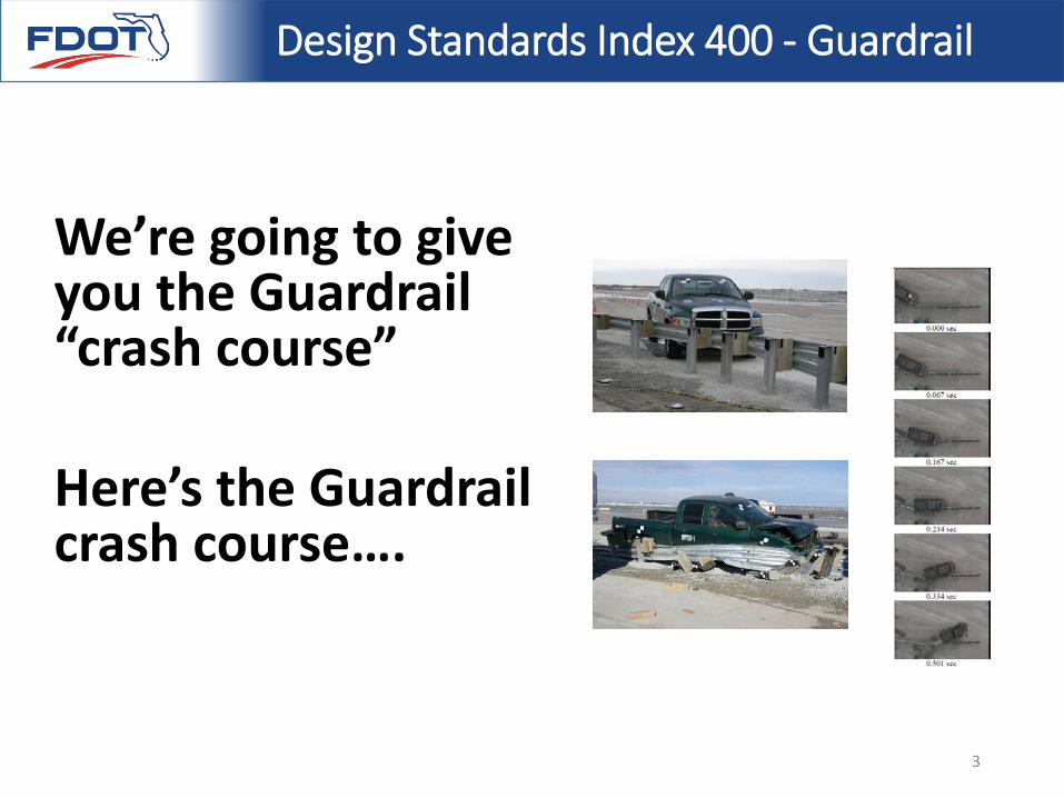
We’re going to give you the Guardrail “crash course”
Here’s the Guardrail crash course….
Design Standards Index 400 - Guardrail
3
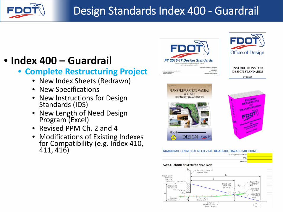
• Index 400 – Guardrail • Complete Restructuring Project
• New Index Sheets (Redrawn)• New Specifications• New Instructions for Design
Standards (IDS)• New Length of Need Design
Program (Excel)• Revised PPM Ch. 2 and 4• Modifications of Existing Indexes
for Compatibility (e.g. Index 410, 411, 416)
Design Standards Index 400 - Guardrail
PPM Update
PART 1: Choosing to Use Guardrail… and Where is Guardrail Located?
Use Plans Preparation Manual (PPM) Volume 1, Chapter 4
5
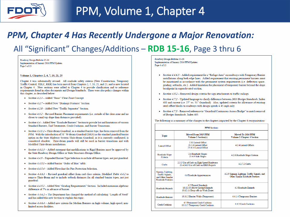
All “Significant” Changes/Additions – RDB 15-16, Page 3 thru 6
PPM, Volume 1, Chapter 4
PPM, Chapter 4 Has Recently Undergone a Major Renovation:
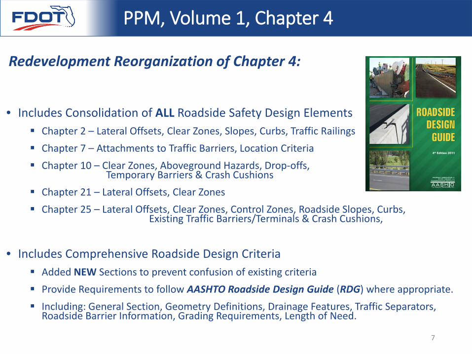
• Includes Consolidation of ALL Roadside Safety Design Elements Chapter 2 – Lateral Offsets, Clear Zones, Slopes, Curbs, Traffic Railings Chapter 7 – Attachments to Traffic Barriers, Location Criteria Chapter 10 – Clear Zones, Aboveground Hazards, Drop-offs,
Temporary Barriers & Crash Cushions Chapter 21 – Lateral Offsets, Clear Zones Chapter 25 – Lateral Offsets, Clear Zones, Control Zones, Roadside Slopes, Curbs,
Existing Traffic Barriers/Terminals & Crash Cushions,
• Includes Comprehensive Roadside Design Criteria Added NEW Sections to prevent confusion of existing criteria Provide Requirements to follow AASHTO Roadside Design Guide (RDG) where appropriate. Including: General Section, Geometry Definitions, Drainage Features, Traffic Separators,
Roadside Barrier Information, Grading Requirements, Length of Need.
PPM, Volume 1, Chapter 4
Redevelopment Reorganization of Chapter 4:
7
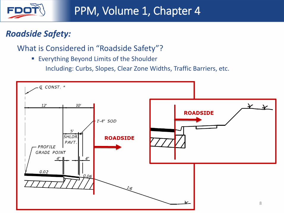
What is Considered in “Roadside Safety”? Everything Beyond Limits of the Shoulder
Including: Curbs, Slopes, Clear Zone Widths, Traffic Barriers, etc.
PPM, Volume 1, Chapter 4
Roadside Safety:
8
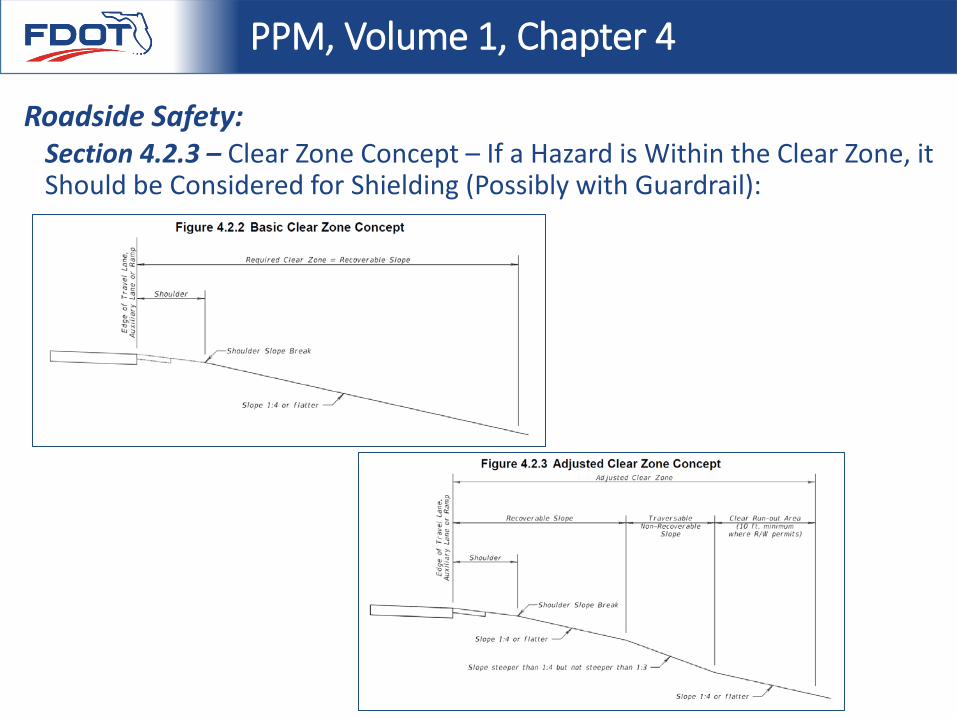
Section 4.2.3 – Clear Zone Concept – If a Hazard is Within the Clear Zone, it Should be Considered for Shielding (Possibly with Guardrail):
PPM, Volume 1, Chapter 4
Roadside Safety:
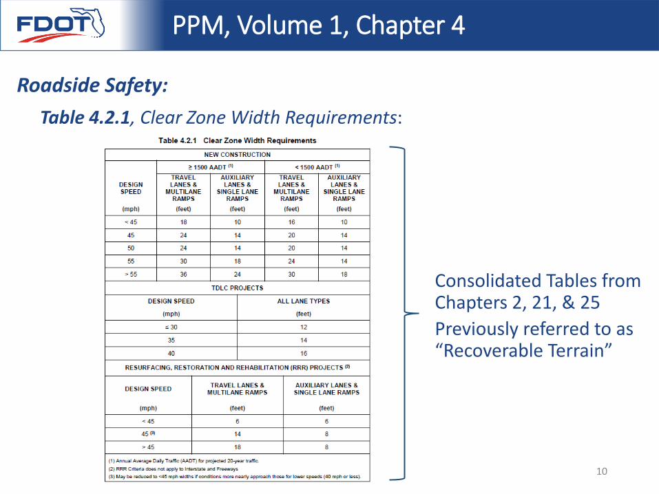
Table 4.2.1, Clear Zone Width Requirements:
PPM, Volume 1, Chapter 4
Roadside Safety:
Consolidated Tables from Chapters 2, 21, & 25Previously referred to as “Recoverable Terrain”
10
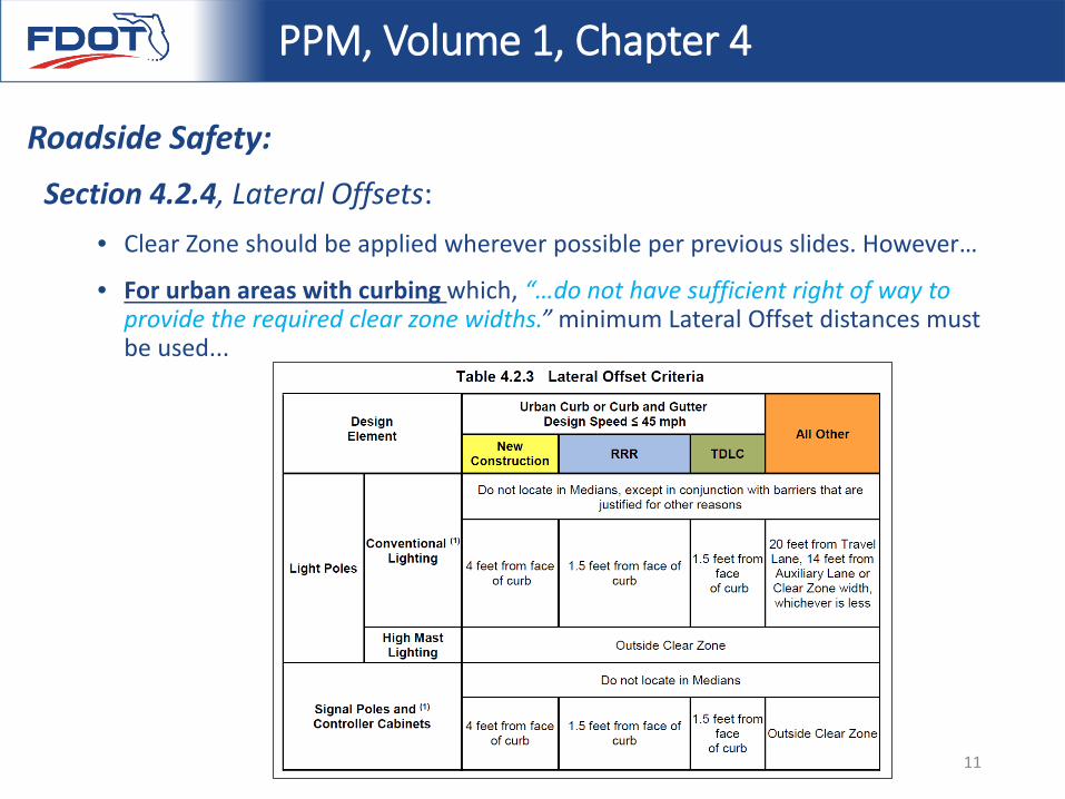
Section 4.2.4, Lateral Offsets:• Clear Zone should be applied wherever possible per previous slides. However…
• For urban areas with curbing which, “…do not have sufficient right of way to provide the required clear zone widths.” minimum Lateral Offset distances must be used...
PPM, Volume 1, Chapter 4
Roadside Safety:
11
Section 4.3, Roadside Hazards:
• Section 4.3.1, Aboveground Hazards
Definition located in Chapter 10 before
“…anything within the Clear Zone that is greater than 4 inches in height and is firm and unyielding or doesn’t meet breakaway criteria.”
Curbs are not considered an aboveground hazard
PPM, Volume 1, Chapter 4
Roadside Safety:
12
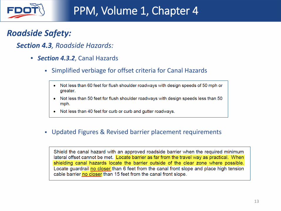
Section 4.3, Roadside Hazards:
• Section 4.3.2, Canal Hazards
Simplified verbiage for offset criteria for Canal Hazards
Updated Figures & Revised barrier placement requirements
PPM, Volume 1, Chapter 4
Roadside Safety:
13
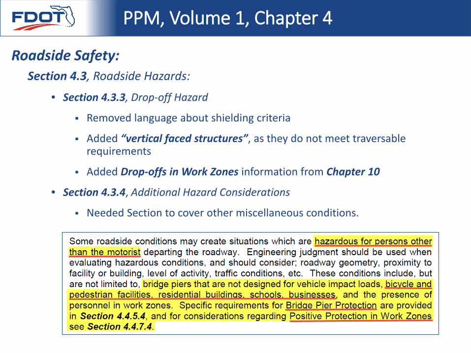
Section 4.3, Roadside Hazards:
• Section 4.3.3, Drop-off Hazard
Removed language about shielding criteria
Added “vertical faced structures”, as they do not meet traversable requirements
Added Drop-offs in Work Zones information from Chapter 10
• Section 4.3.4, Additional Hazard Considerations
Needed Section to cover other miscellaneous conditions.
PPM, Volume 1, Chapter 4
Roadside Safety:
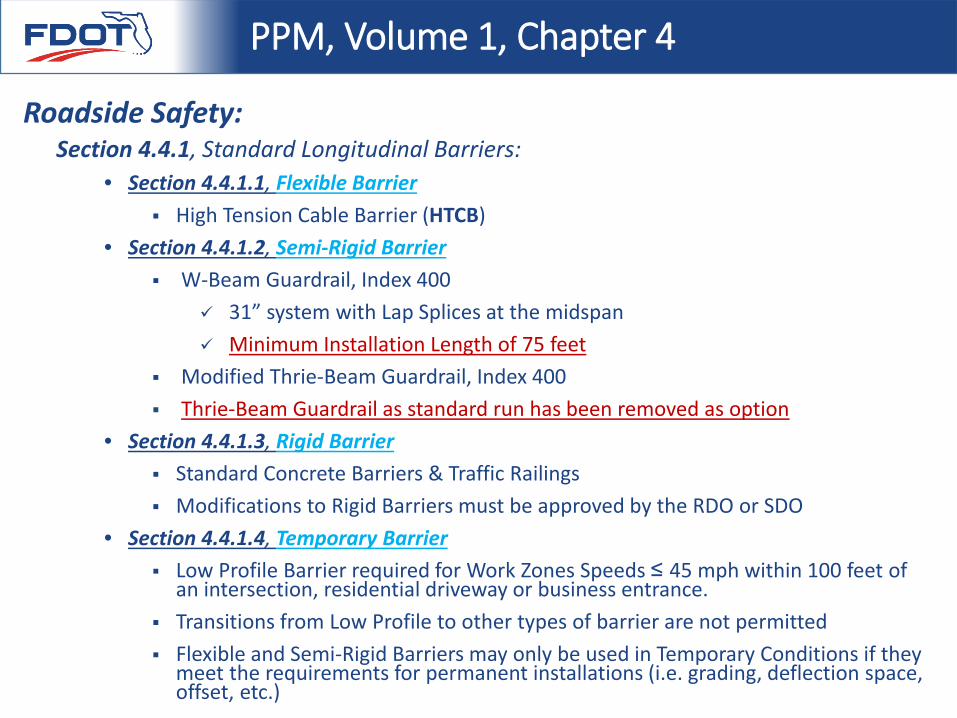
Section 4.4.1, Standard Longitudinal Barriers:• Section 4.4.1.1, Flexible Barrier
High Tension Cable Barrier (HTCB) • Section 4.4.1.2, Semi-Rigid Barrier
W-Beam Guardrail, Index 400 31” system with Lap Splices at the midspan Minimum Installation Length of 75 feet
Modified Thrie-Beam Guardrail, Index 400 Thrie-Beam Guardrail as standard run has been removed as option
• Section 4.4.1.3, Rigid Barrier Standard Concrete Barriers & Traffic Railings Modifications to Rigid Barriers must be approved by the RDO or SDO
• Section 4.4.1.4, Temporary Barrier Low Profile Barrier required for Work Zones Speeds ≤ 45 mph within 100 feet of
an intersection, residential driveway or business entrance. Transitions from Low Profile to other types of barrier are not permitted Flexible and Semi-Rigid Barriers may only be used in Temporary Conditions if they
meet the requirements for permanent installations (i.e. grading, deflection space, offset, etc.)
PPM, Volume 1, Chapter 4
Roadside Safety:
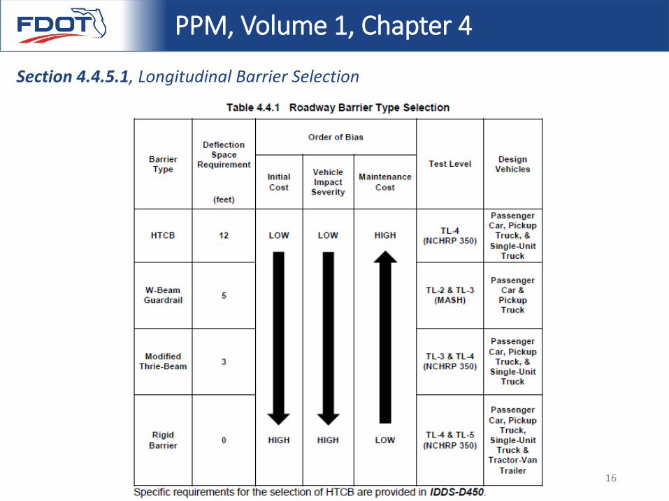
Section 4.4.5.1, Longitudinal Barrier Selection
PPM, Volume 1, Chapter 4
16
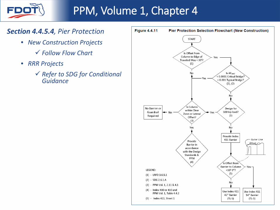
Section 4.4.5.4, Pier Protection• New Construction Projects
Follow Flow Chart• RRR Projects
Refer to SDG for Conditional Guidance
PPM, Volume 1, Chapter 4
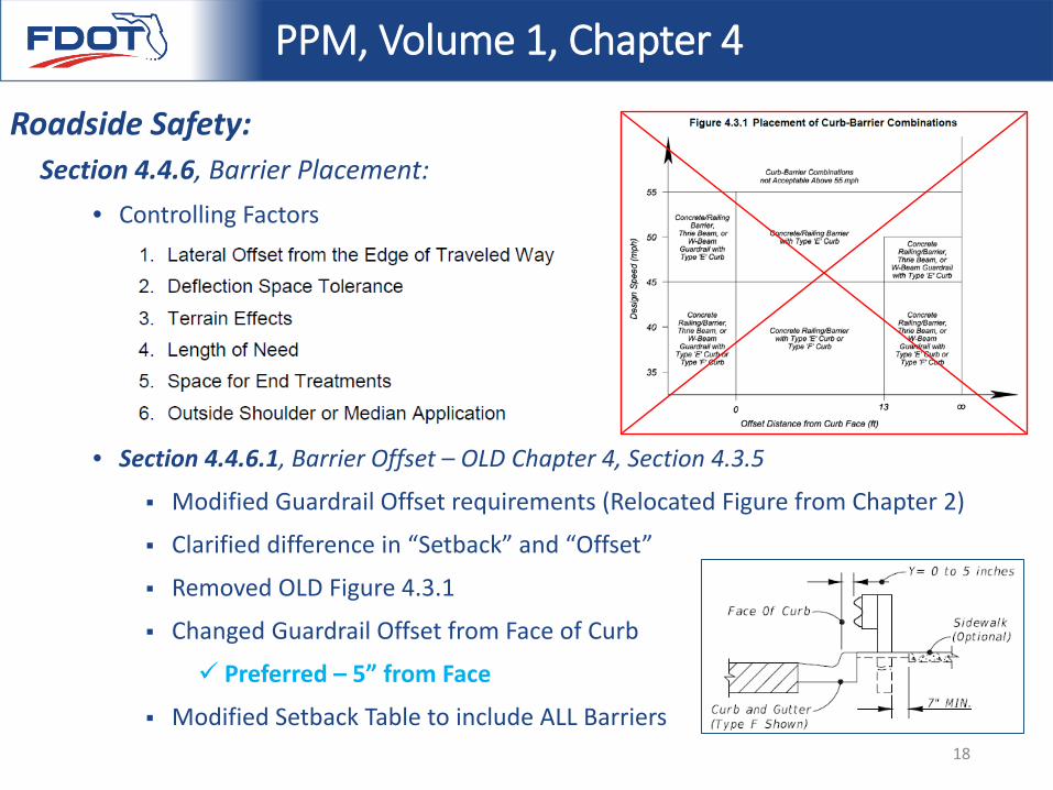
Section 4.4.6, Barrier Placement:• Controlling Factors
• Section 4.4.6.1, Barrier Offset – OLD Chapter 4, Section 4.3.5
Modified Guardrail Offset requirements (Relocated Figure from Chapter 2)
Clarified difference in “Setback” and “Offset”
Removed OLD Figure 4.3.1
Changed Guardrail Offset from Face of Curb
Preferred – 5” from Face
Modified Setback Table to include ALL Barriers
PPM, Volume 1, Chapter 4
Roadside Safety:
18
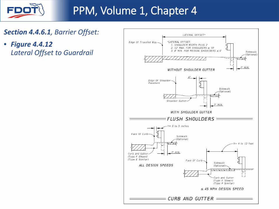
Section 4.4.6.1, Barrier Offset:
• Figure 4.4.12 Lateral Offset to Guardrail
PPM, Volume 1, Chapter 4
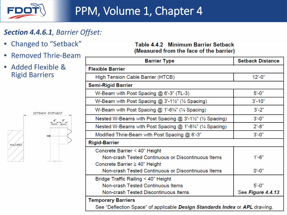
Section 4.4.6.1, Barrier Offset:• Changed to “Setback”• Removed Thrie-Beam• Added Flexible &
Rigid Barriers
PPM, Volume 1, Chapter 4
Section 4.4.6, Barrier Placement:
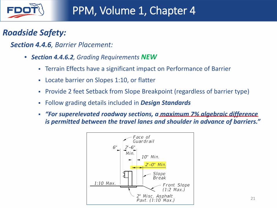
• Section 4.4.6.2, Grading Requirements NEW Terrain Effects have a significant impact on Performance of Barrier
Locate barrier on Slopes 1:10, or flatter
Provide 2 feet Setback from Slope Breakpoint (regardless of barrier type)
Follow grading details included in Design Standards
“For superelevated roadway sections, a maximum 7% algebraic difference is permitted between the travel lanes and shoulder in advance of barriers.”
PPM, Volume 1, Chapter 4
Roadside Safety:
21
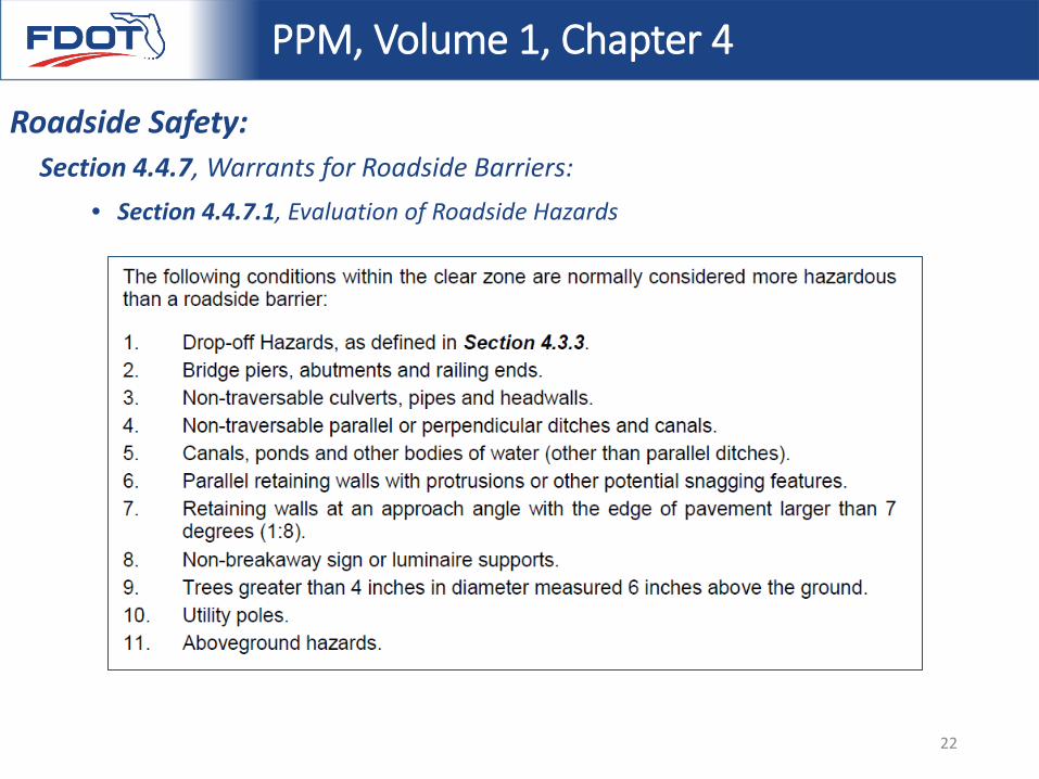
Section 4.4.7, Warrants for Roadside Barriers:• Section 4.4.7.1, Evaluation of Roadside Hazards
PPM, Volume 1, Chapter 4
Roadside Safety:
22
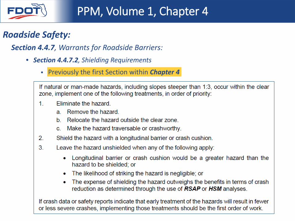
Section 4.4.7, Warrants for Roadside Barriers:• Section 4.4.7.2, Shielding Requirements
Previously the first Section within Chapter 4
PPM, Volume 1, Chapter 4
Roadside Safety:
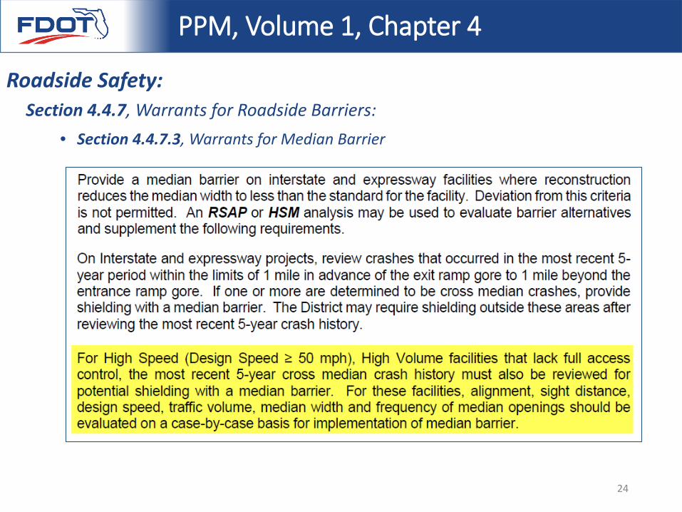
Section 4.4.7, Warrants for Roadside Barriers:• Section 4.4.7.3, Warrants for Median Barrier
PPM, Volume 1, Chapter 4
Roadside Safety:
24
Design Standards Index 400 - Guardrail
PART 2: Index Sheets Overview
Index 400 is a DSR, as of February 1, 2016 25
Design Standards Index 400 - Guardrail
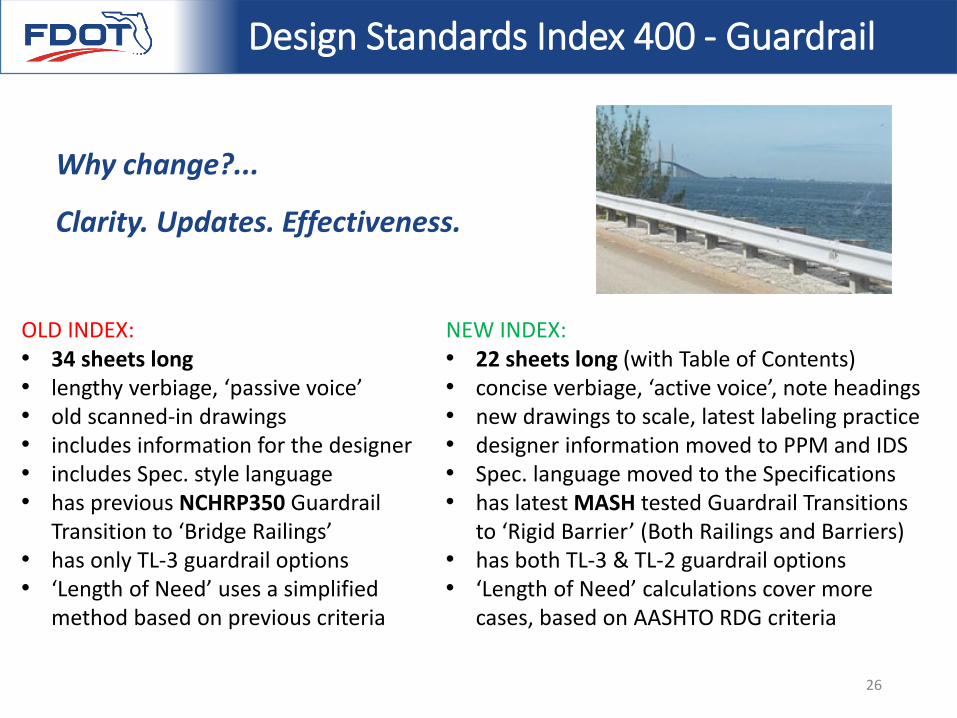
OLD INDEX:• 34 sheets long • lengthy verbiage, ‘passive voice’• old scanned-in drawings• includes information for the designer• includes Spec. style language• has previous NCHRP350 Guardrail
Transition to ‘Bridge Railings’• has only TL-3 guardrail options• ‘Length of Need’ uses a simplified
method based on previous criteria
NEW INDEX:• 22 sheets long (with Table of Contents)• concise verbiage, ‘active voice’, note headings• new drawings to scale, latest labeling practice• designer information moved to PPM and IDS• Spec. language moved to the Specifications• has latest MASH tested Guardrail Transitions
to ‘Rigid Barrier’ (Both Railings and Barriers)• has both TL-3 & TL-2 guardrail options• ‘Length of Need’ calculations cover more
cases, based on AASHTO RDG criteria
Why change?...
Clarity. Updates. Effectiveness.
26
Design Standards Index 400 - Guardrail
27
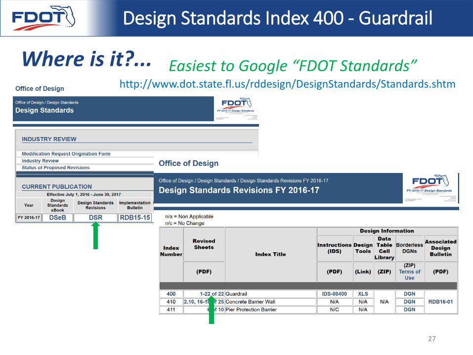
Where is it?...http://www.dot.state.fl.us/rddesign/DesignStandards/Standards.shtm
Easiest to Google “FDOT Standards”
Design Standards Index 400 - Guardrail
The Index Sheets and Instructions for Design Standards discussed refer to the February 1st DSR to the 2016-17 Design Standards eBook. The Specifications referred to will soon be available as Modified Special Provisions (MSPs).
These documents are available for use at the option of the Districts for all FDOT projects let prior to July 1st, 2017.
On July 1st, 2017 this update will become mandatory for FDOT projects, as it will be released with the 2017-18 Design Standards eBook.
Implementation Schedule…Roadway Design Bulletin 16-01
28
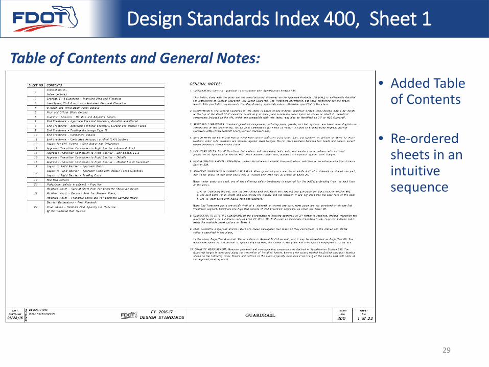
• Added Table of Contents
• Re-ordered sheets in an intuitive sequence
Design Standards Index 400, Sheet 1
Table of Contents and General Notes:
29
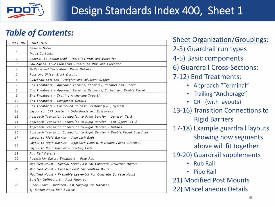
Sheet Organization/Groupings:2-3) Guardrail run types4-5) Basic components6) Guardrail Cross-Sections: 7-12) End Treatments:
• Approach “Terminal”• Trailing “Anchorage”• CRT (with layouts)
13-16) Transition Connections to Rigid Barriers
17-18) Example guardrail layouts showing how segments above will fit together
19-20) Guardrail supplements• Rub Rail• Pipe Rail
21) Modified Post Mounts22) Miscellaneous Details
Design Standards Index 400, Sheet 1
Table of Contents:
30
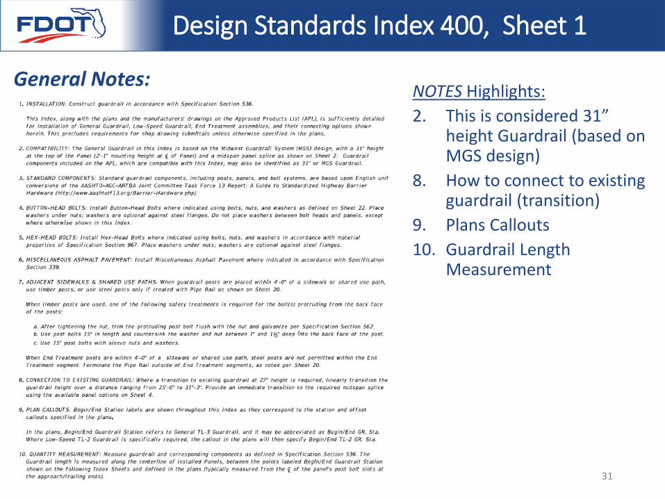
NOTES Highlights:2. This is considered 31”
height Guardrail (based on MGS design)
8. How to connect to existing guardrail (transition)
9. Plans Callouts10. Guardrail Length
Measurement
Design Standards Index 400, Sheet 1
General Notes:
31
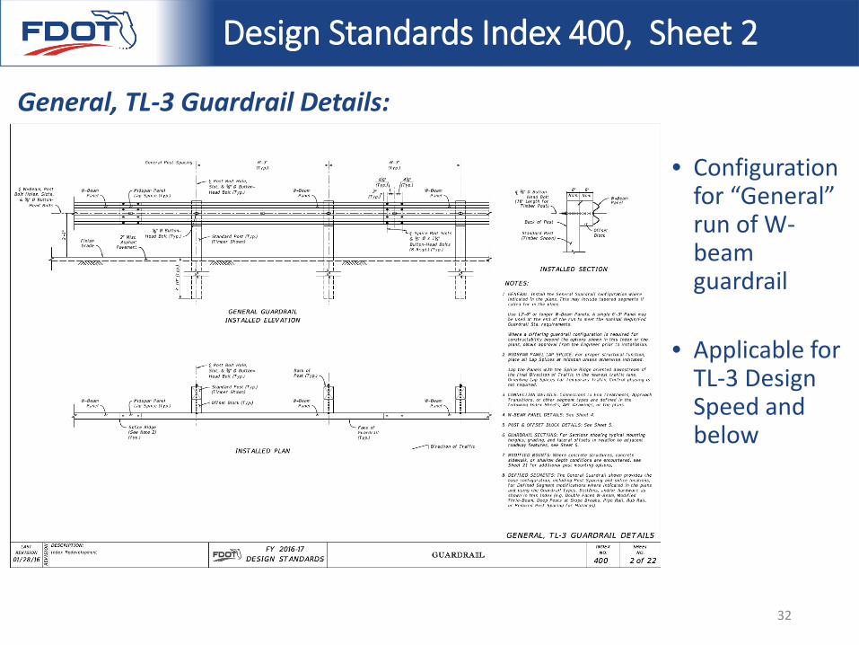
• Configuration for “General” run of W-beam guardrail
• Applicable for TL-3 Design Speed and below
Design Standards Index 400, Sheet 2
General, TL-3 Guardrail Details:
32
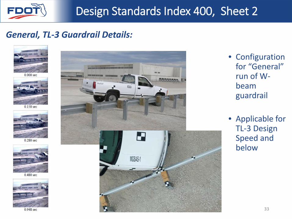
• Configuration for “General” run of W-beam guardrail
• Applicable for TL-3 Design Speed and below
Design Standards Index 400, Sheet 2
General, TL-3 Guardrail Details:
33
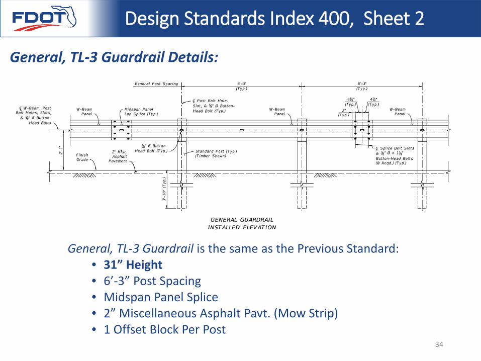
General, TL-3 Guardrail is the same as the Previous Standard:• 31” Height• 6’-3” Post Spacing• Midspan Panel Splice• 2” Miscellaneous Asphalt Pavt. (Mow Strip)• 1 Offset Block Per Post
Design Standards Index 400, Sheet 2
General, TL-3 Guardrail Details:
34
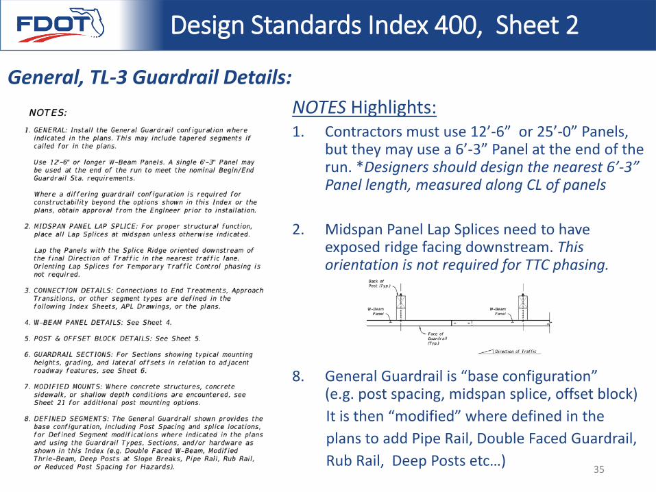
NOTES Highlights:1. Contractors must use 12’-6” or 25’-0” Panels,
but they may use a 6’-3” Panel at the end of the run. *Designers should design the nearest 6’-3” Panel length, measured along CL of panels
2. Midspan Panel Lap Splices need to have exposed ridge facing downstream. This orientation is not required for TTC phasing.
8. General Guardrail is “base configuration” (e.g. post spacing, midspan splice, offset block)It is then “modified” where defined in the plans to add Pipe Rail, Double Faced Guardrail, Rub Rail, Deep Posts etc…)
Design Standards Index 400, Sheet 2
General, TL-3 Guardrail Details:
35
Low-Speed, TL-2 Guardrail Details:
Design Standards Index 400, Sheet 3
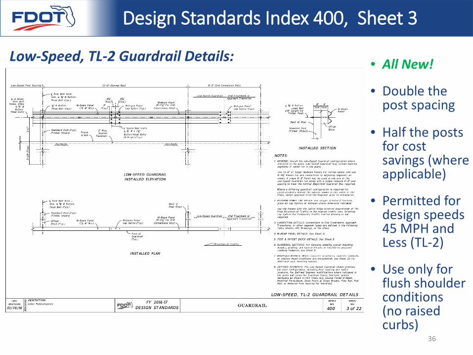
• All New!
• Double the post spacing
• Half the posts for cost savings (where applicable)
• Permitted for design speeds 45 MPH and Less (TL-2)
• Use only for flush shoulder conditions (no raised curbs)
36
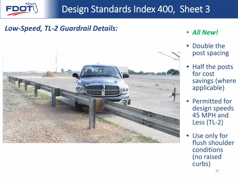
Low-Speed, TL-2 Guardrail Details:
Design Standards Index 400, Sheet 3
• All New!
• Double the post spacing
• Half the posts for cost savings (where applicable)
• Permitted for design speeds 45 MPH and Less (TL-2)
• Use only for flush shoulder conditions (no raised curbs)
37
Low-Speed, TL-2 Guardrail Details:
Design Standards Index 400, Sheet 3
38
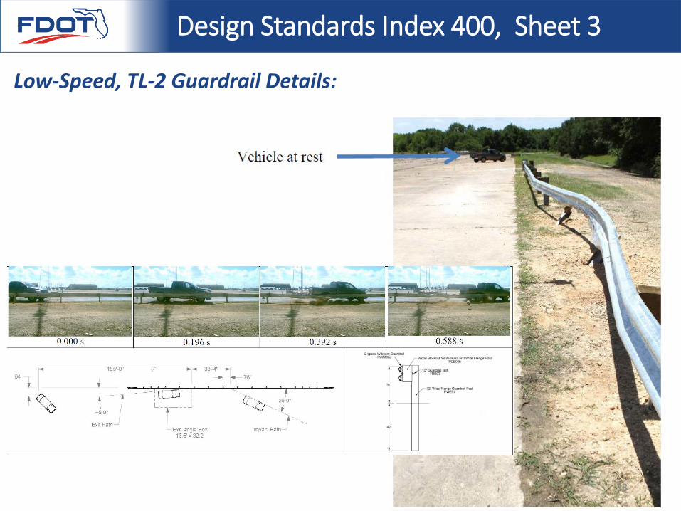
Low-Speed, TL-2 Guardrail Details:
Design Standards Index 400, Sheet 3
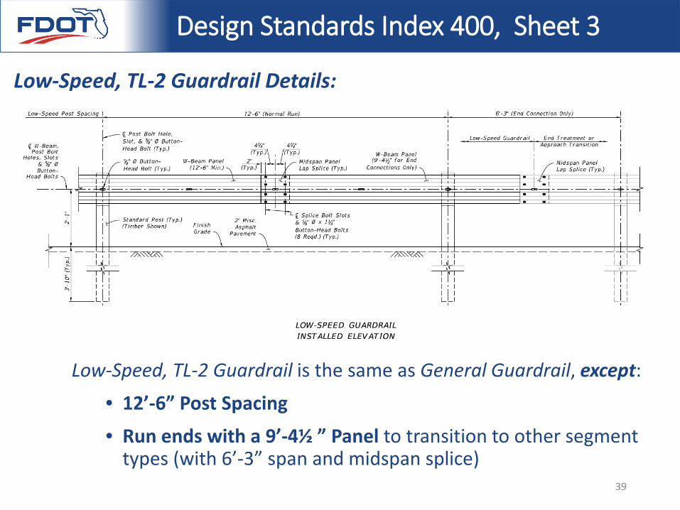
Low-Speed, TL-2 Guardrail is the same as General Guardrail, except:
• 12’-6” Post Spacing
• Run ends with a 9’-4½ ” Panel to transition to other segment types (with 6’-3” span and midspan splice)
39
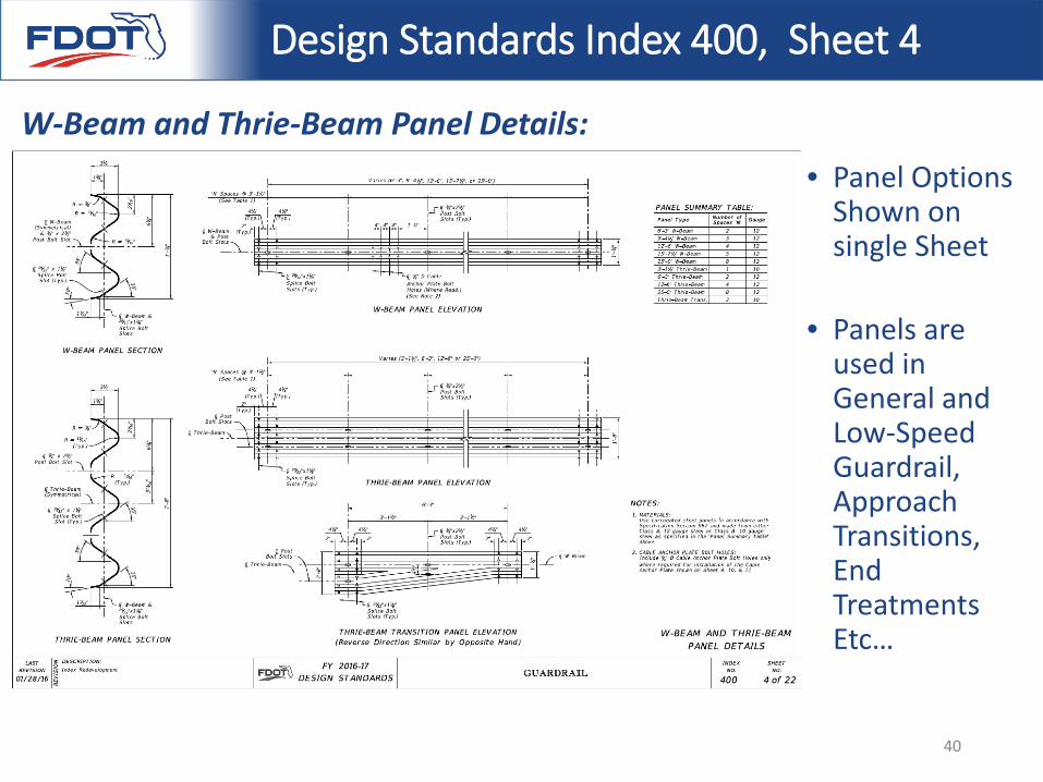
• Panel Options Shown on single Sheet
• Panels are used in General and Low-Speed Guardrail, Approach Transitions, End Treatments Etc…
Design Standards Index 400, Sheet 4
W-Beam and Thrie-Beam Panel Details:
40
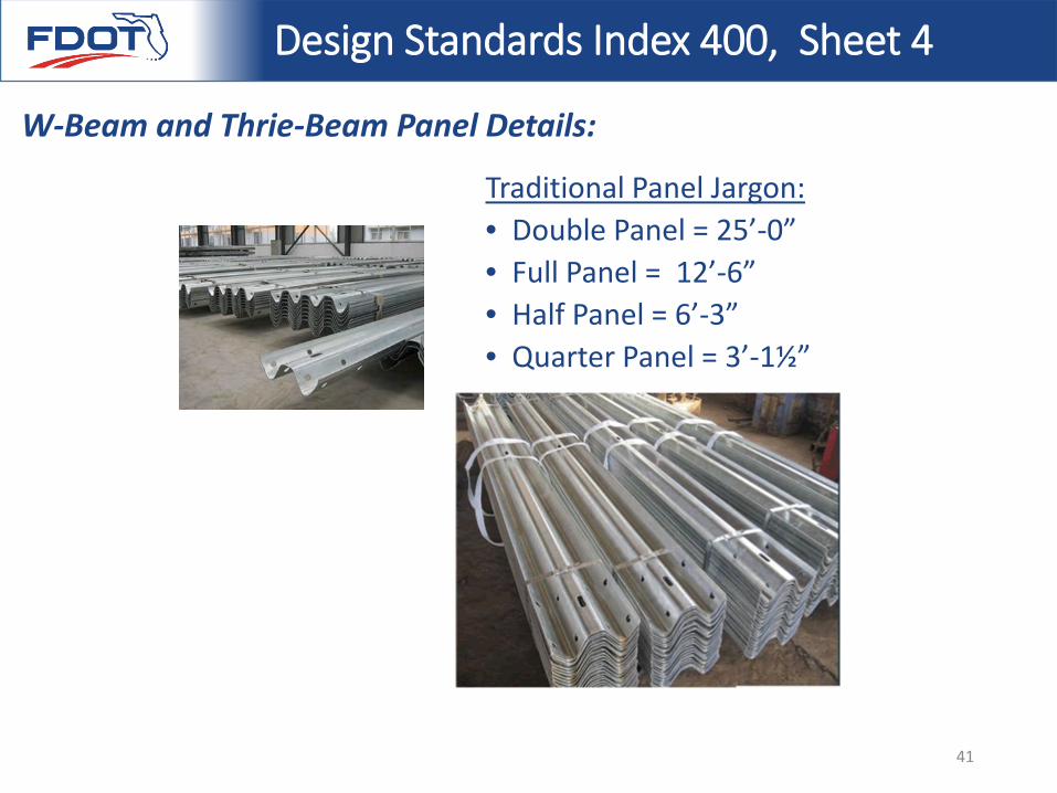
Traditional Panel Jargon:• Double Panel = 25’-0”• Full Panel = 12’-6”• Half Panel = 6’-3”• Quarter Panel = 3’-1½”
Design Standards Index 400, Sheet 4
W-Beam and Thrie-Beam Panel Details:
41
Design Standards Index 400, Sheet 4
W-Beam and Thrie-Beam Panel Details:
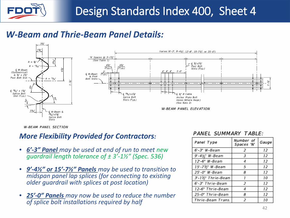
More Flexibility Provided for Contractors:
• 6’-3” Panel may be used at end of run to meet new guardrail length tolerance of ± 3’-1½” (Spec. 536)
• 9’-4½” or 15’-7½” Panels may be used to transition to midspan panel lap splices (for connecting to existing older guardrail with splices at post location)
• 25’-0” Panels may now be used to reduce the number of splice bolt installations required by half
42
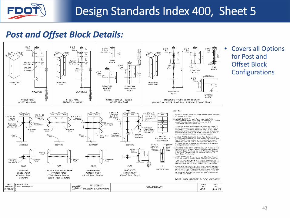
• Covers all Options for Post and Offset Block Configurations
Design Standards Index 400, Sheet 5
Post and Offset Block Details:
43
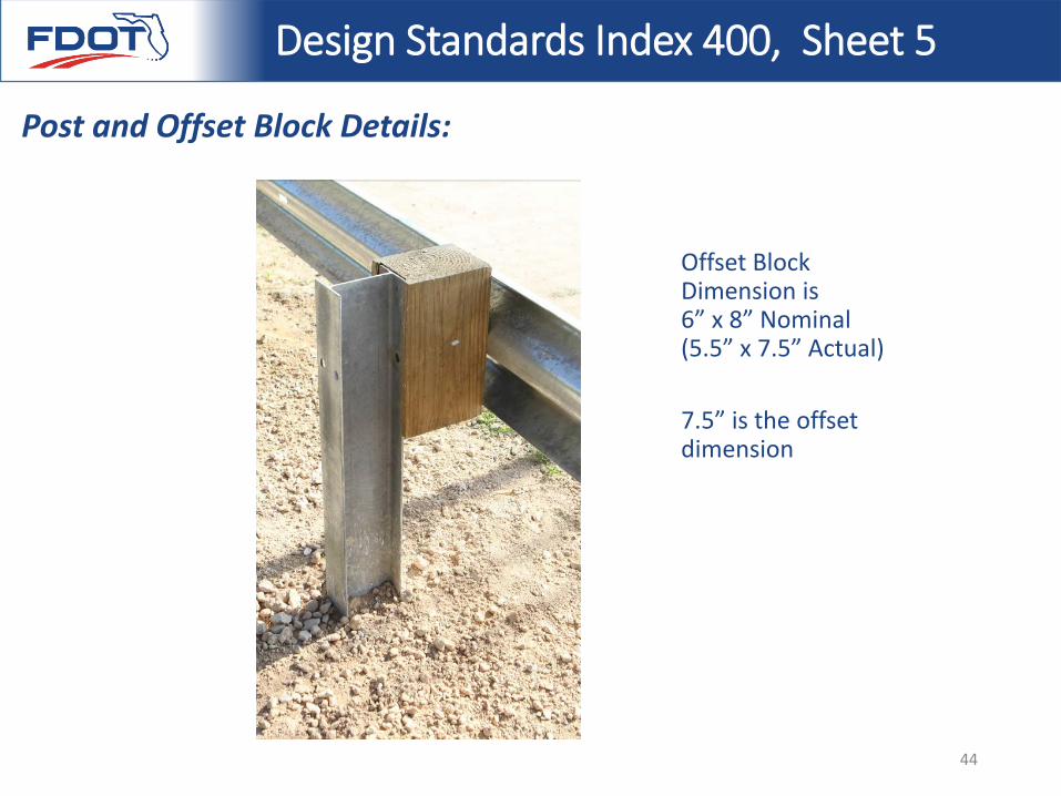
Offset Block Dimension is 6” x 8” Nominal (5.5” x 7.5” Actual)
7.5” is the offset dimension
Design Standards Index 400, Sheet 5
Post and Offset Block Details:
44
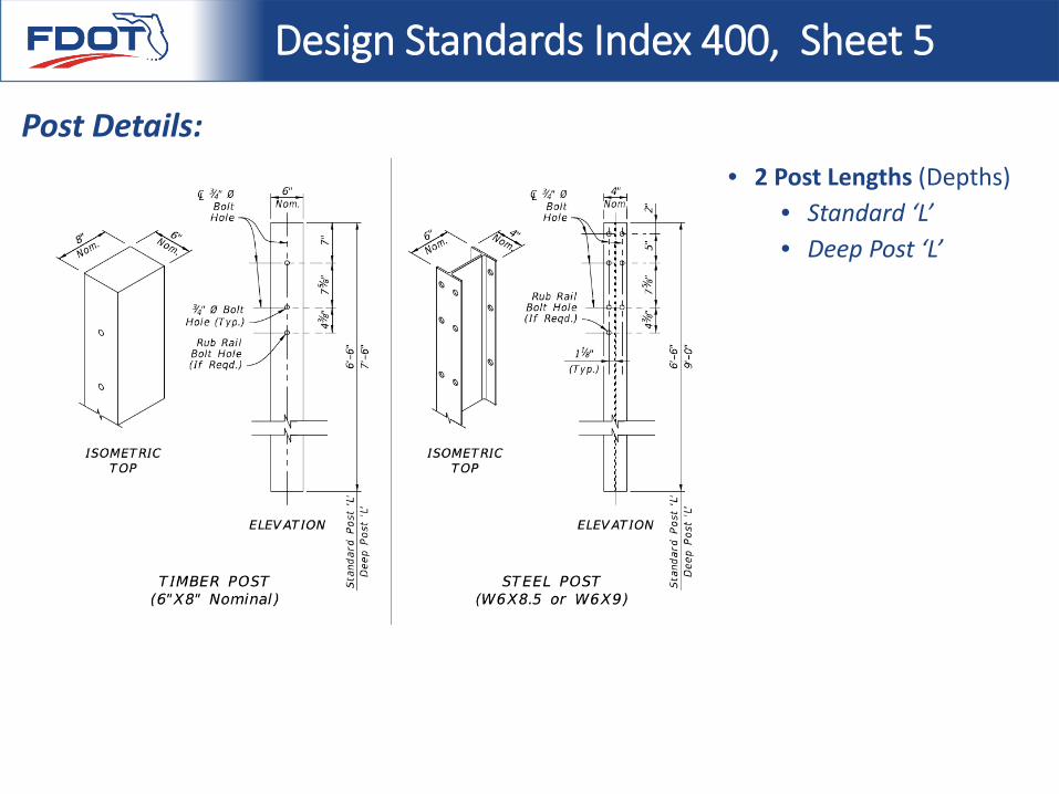
• 2 Post Lengths (Depths)• Standard ‘L’• Deep Post ‘L’
Design Standards Index 400, Sheet 5
Post Details:
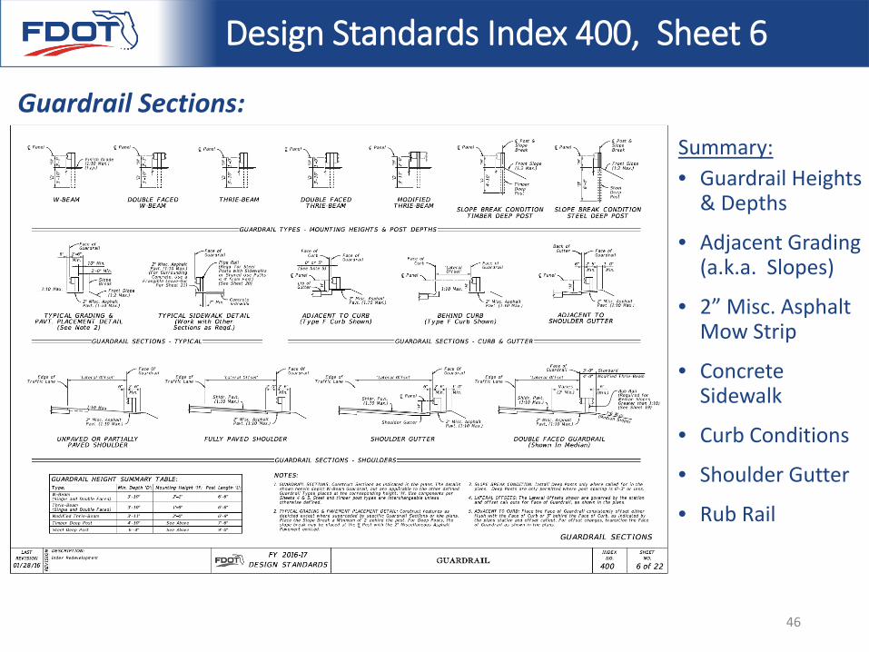
Summary:• Guardrail Heights
& Depths
• Adjacent Grading (a.k.a. Slopes)
• 2” Misc. Asphalt Mow Strip
• Concrete Sidewalk
• Curb Conditions
• Shoulder Gutter
• Rub Rail
Design Standards Index 400, Sheet 6
Guardrail Sections:
46
Design Standards Index 400, Sheet 6
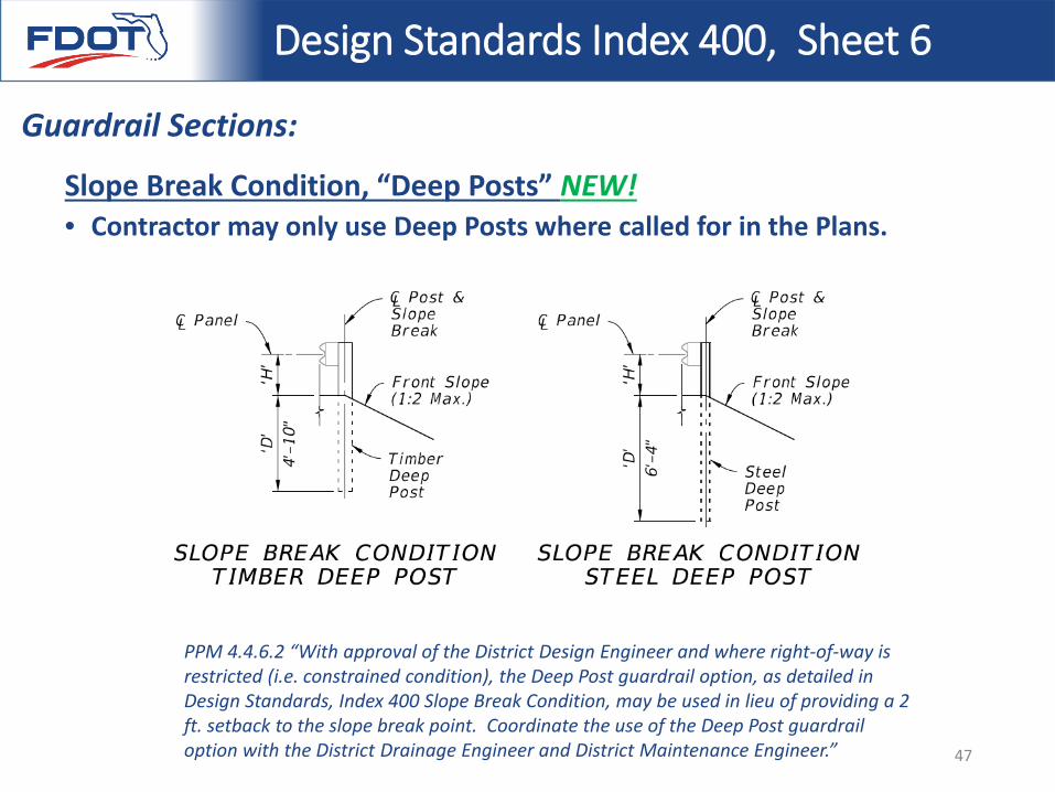
Guardrail Sections:
Slope Break Condition, “Deep Posts” NEW!• Contractor may only use Deep Posts where called for in the Plans.
PPM 4.4.6.2 “With approval of the District Design Engineer and where right-of-way is restricted (i.e. constrained condition), the Deep Post guardrail option, as detailed in Design Standards, Index 400 Slope Break Condition, may be used in lieu of providing a 2 ft. setback to the slope break point. Coordinate the use of the Deep Post guardrail option with the District Drainage Engineer and District Maintenance Engineer.” 47
Design Standards Index 400, Sheet 6
Guardrail Sections:
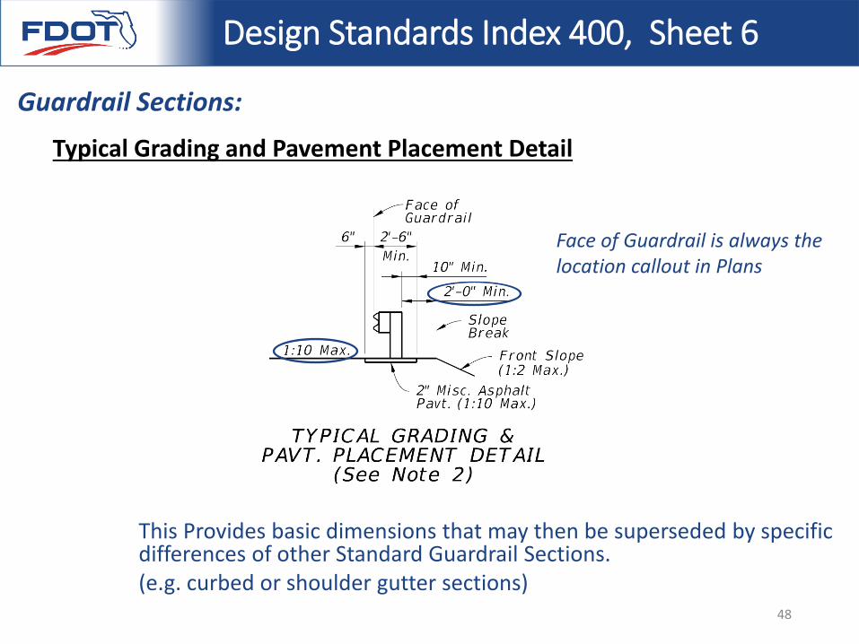
Typical Grading and Pavement Placement Detail
This Provides basic dimensions that may then be superseded by specific differences of other Standard Guardrail Sections. (e.g. curbed or shoulder gutter sections)
Face of Guardrail is always the location callout in Plans
48
Design Standards Index 400, Sheet 6
Guardrail Sections:
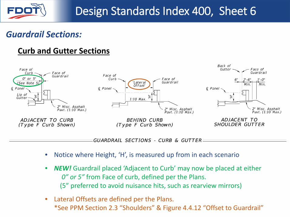
Curb and Gutter Sections
• Notice where Height, ‘H’, is measured up from in each scenario
• NEW! Guardrail placed ‘Adjacent to Curb’ may now be placed at either 0” or 5” from Face of curb, defined per the Plans.
(5” preferred to avoid nuisance hits, such as rearview mirrors)
• Lateral Offsets are defined per the Plans. *See PPM Section 2.3 “Shoulders” & Figure 4.4.12 “Offset to Guardrail”
Design Standards Index 400, Sheet 6
Guardrail Sections:
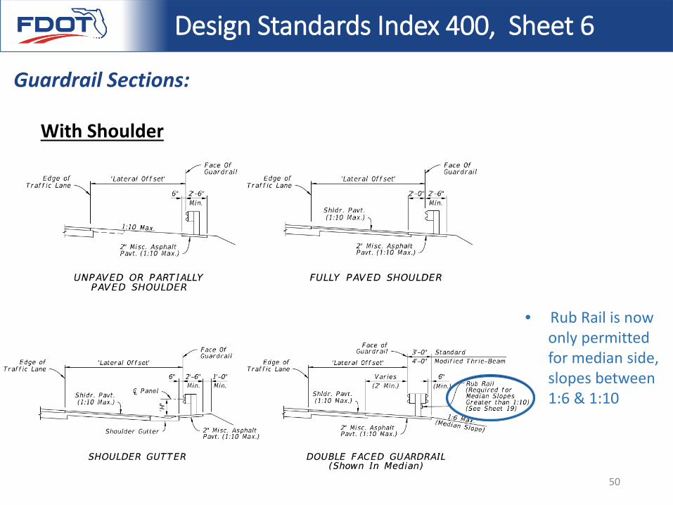
With Shoulder
• Rub Rail is now only permitted for median side, slopes between 1:6 & 1:10
50
Design Standards Index 400, Sheet 6
Guardrail Sections:
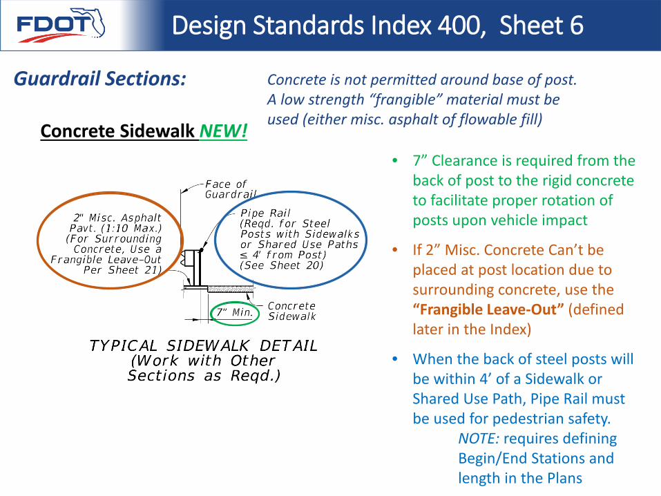
Concrete Sidewalk NEW!• 7” Clearance is required from the
back of post to the rigid concrete to facilitate proper rotation of posts upon vehicle impact
• If 2” Misc. Concrete Can’t be placed at post location due to surrounding concrete, use the “Frangible Leave-Out” (defined later in the Index)
• When the back of steel posts will be within 4’ of a Sidewalk or Shared Use Path, Pipe Rail must be used for pedestrian safety.
NOTE: requires defining Begin/End Stations and length in the Plans
Concrete is not permitted around base of post. A low strength “frangible” material must be used (either misc. asphalt of flowable fill)
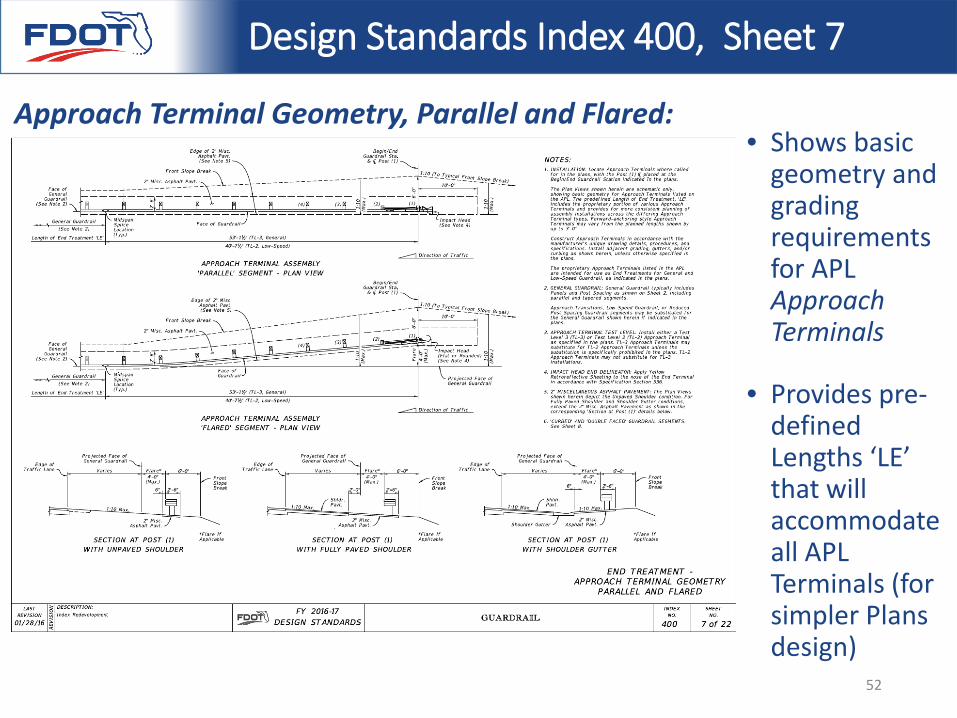
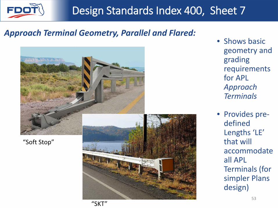
• Shows basic geometry and grading requirements for APL Approach Terminals
• Provides pre-defined Lengths ‘LE’ that will accommodate all APL Terminals (for simpler Plans design)
Design Standards Index 400, Sheet 7
Approach Terminal Geometry, Parallel and Flared:
52
• Shows basic geometry and grading requirements for APL Approach Terminals
• Provides pre-defined Lengths ‘LE’ that will accommodate all APL Terminals (for simpler Plans design)
Design Standards Index 400, Sheet 7
Approach Terminal Geometry, Parallel and Flared:
“Soft Stop”
“SKT”53
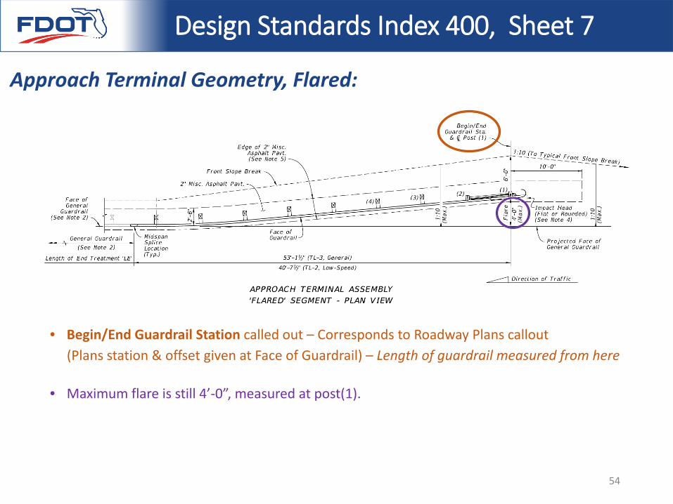
Design Standards Index 400, Sheet 7
Approach Terminal Geometry, Flared:
• Begin/End Guardrail Station called out – Corresponds to Roadway Plans callout (Plans station & offset given at Face of Guardrail) – Length of guardrail measured from here
• Maximum flare is still 4’-0”, measured at post(1).
54
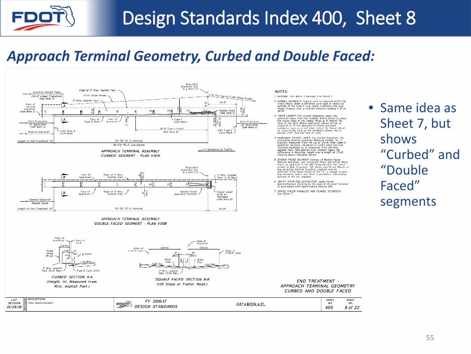
Design Standards Index 400, Sheet 8
Approach Terminal Geometry, Curbed and Double Faced:
• Same idea as Sheet 7, but shows “Curbed” and “Double Faced” segments
55
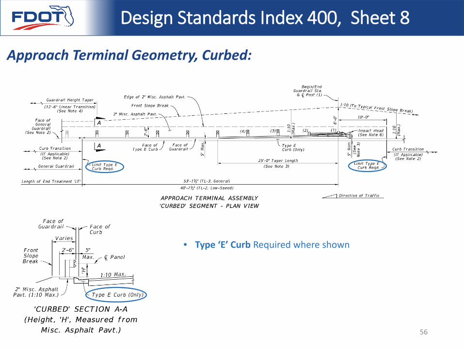
Design Standards Index 400, Sheet 8
Approach Terminal Geometry, Curbed:
• Type ‘E’ Curb Required where shown
56
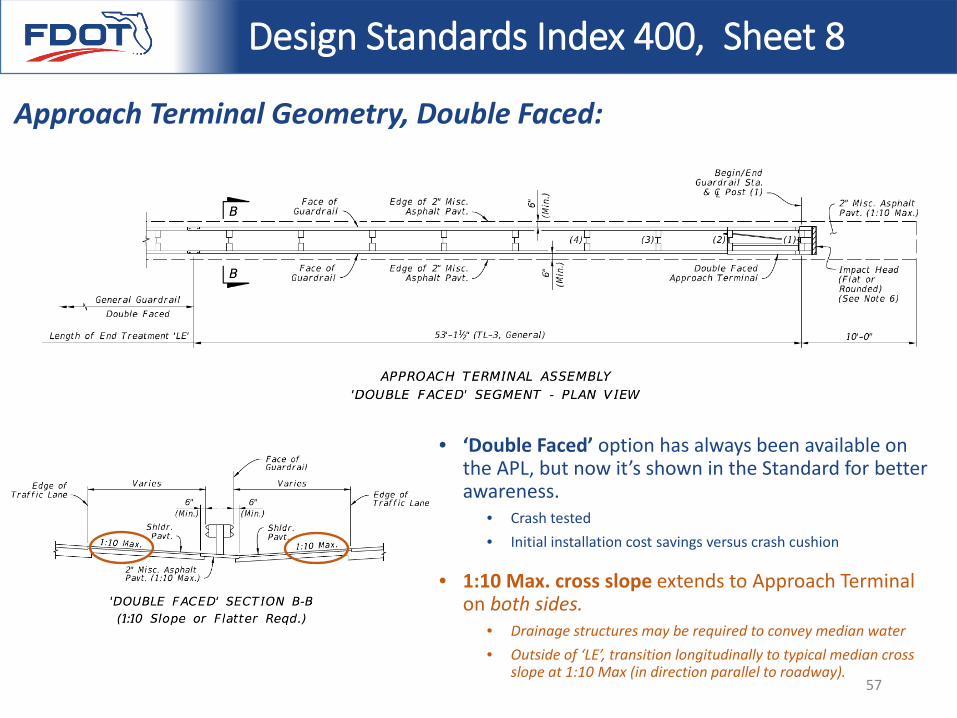
Design Standards Index 400, Sheet 8
Approach Terminal Geometry, Double Faced:
• ‘Double Faced’ option has always been available on the APL, but now it’s shown in the Standard for better awareness.
• Crash tested• Initial installation cost savings versus crash cushion
• 1:10 Max. cross slope extends to Approach Terminal on both sides.
• Drainage structures may be required to convey median water• Outside of ‘LE’, transition longitudinally to typical median cross
slope at 1:10 Max (in direction parallel to roadway). 57
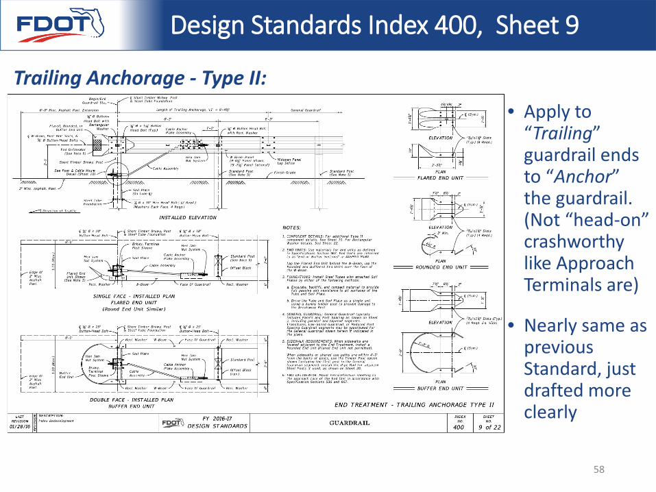
Design Standards Index 400, Sheet 9
Trailing Anchorage - Type II:• Apply to
“Trailing” guardrail ends to “Anchor” the guardrail. (Not “head-on” crashworthy like Approach Terminals are)
• Nearly same as previous Standard, just drafted more clearly
58
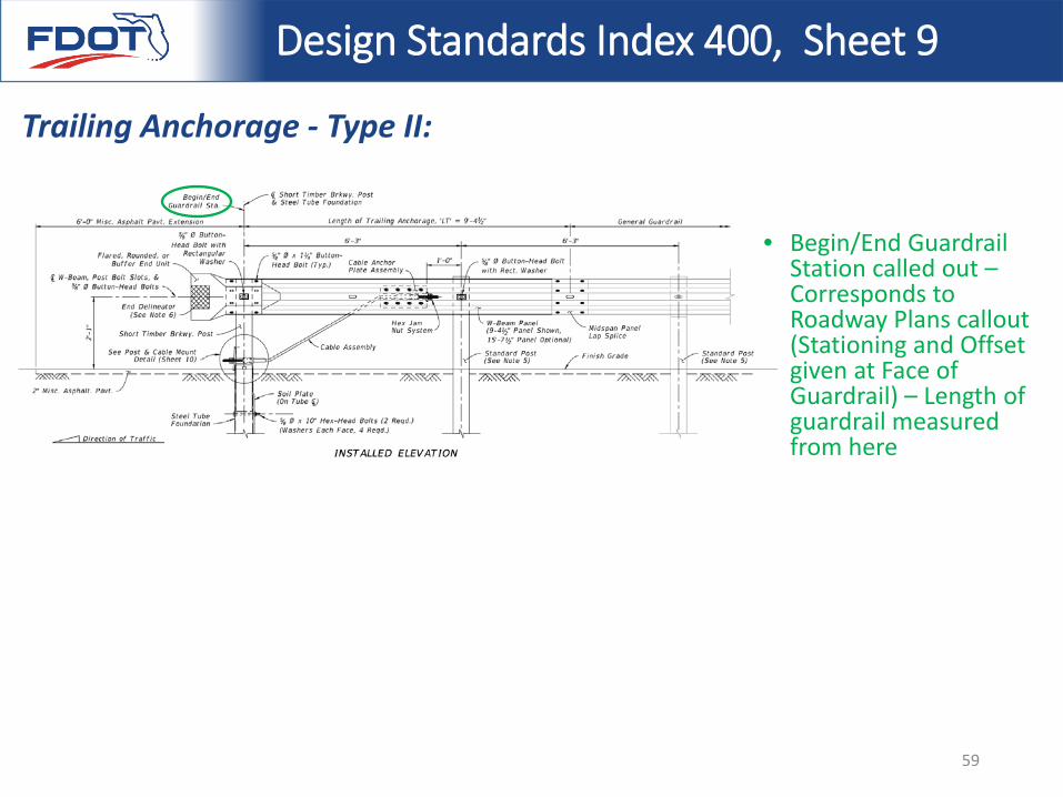
Design Standards Index 400, Sheet 9
Trailing Anchorage - Type II:
• Begin/End Guardrail Station called out –Corresponds to Roadway Plans callout (Stationing and Offset given at Face of Guardrail) – Length of guardrail measured from here
59
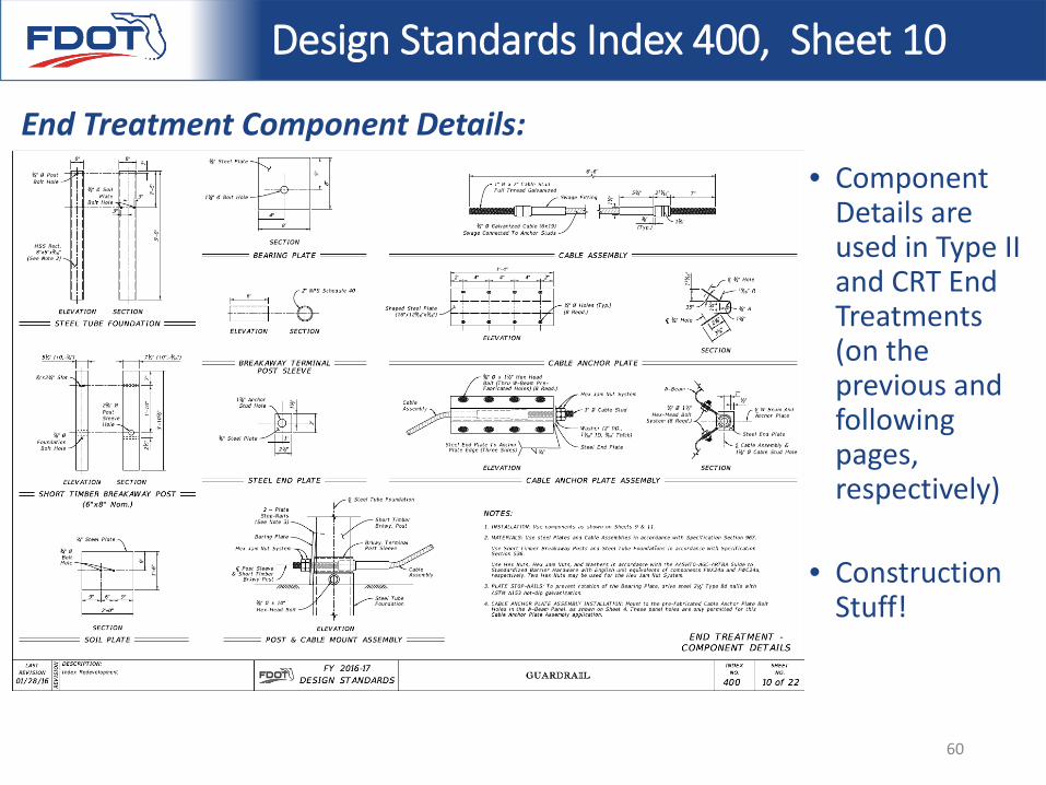
Design Standards Index 400, Sheet 10
End Treatment Component Details:• Component
Details are used in Type II and CRT End Treatments (on the previous and following pages, respectively)
• Construction Stuff!
60
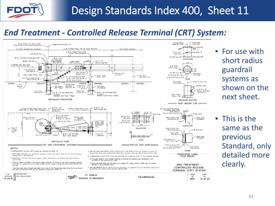
Design Standards Index 400, Sheet 11
End Treatment - Controlled Release Terminal (CRT) System:
• For use with short radius guardrail systems as shown on the next sheet.
• This is the same as the previous Standard, only detailed more clearly.
61
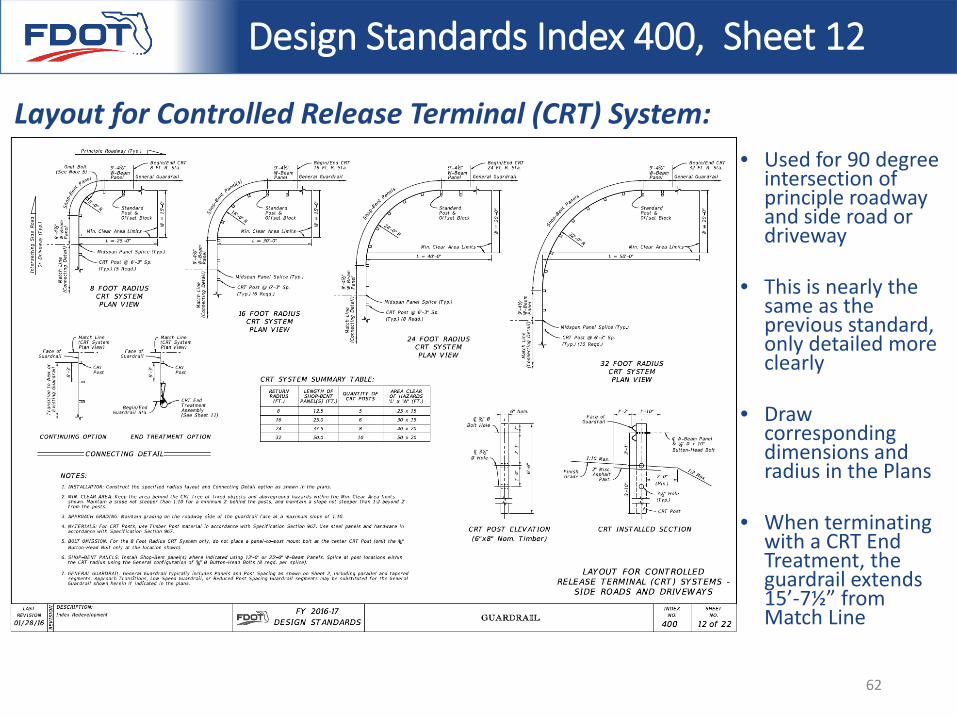
Design Standards Index 400, Sheet 12
Layout for Controlled Release Terminal (CRT) System:• Used for 90 degree
intersection of principle roadway and side road or driveway
• This is nearly the same as the previous standard, only detailed more clearly
• Draw corresponding dimensions and radius in the Plans
• When terminating with a CRT End Treatment, the guardrail extends 15’-7½” from Match Line
62
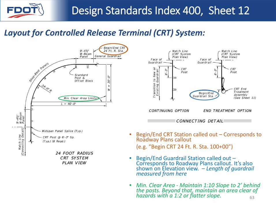
Design Standards Index 400, Sheet 12
Layout for Controlled Release Terminal (CRT) System:
• Begin/End CRT Station called out – Corresponds to Roadway Plans callout(e.g. “Begin CRT 24 Ft. R. Sta. 100+00”)
• Begin/End Guardrail Station called out –Corresponds to Roadway Plans callout. It’s also shown on Elevation view. – Length of guardrail measured from here
• Min. Clear Area - Maintain 1:10 Slope to 2’ behind the posts. Beyond that, maintain an area clear of hazards with a 1:2 or flatter slope. 63
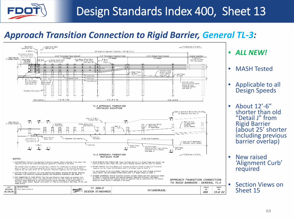
Design Standards Index 400, Sheet 13
Approach Transition Connection to Rigid Barrier, General TL-3:
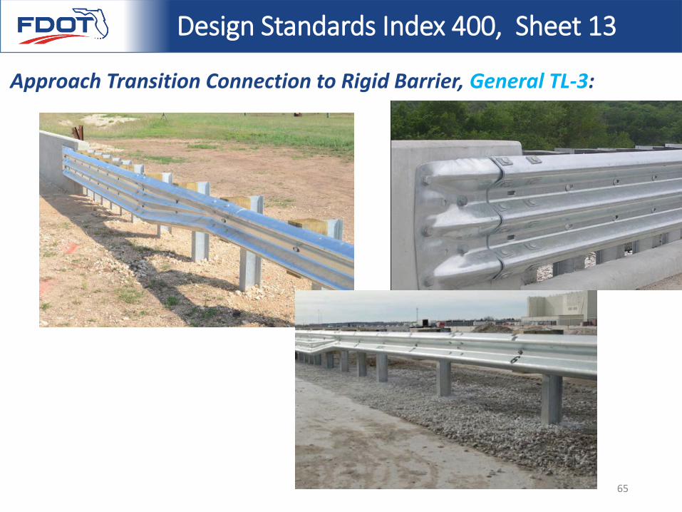
• ALL NEW!
• MASH Tested
• Applicable to all Design Speeds
• About 12’-6” shorter than old “Detail J” from Rigid Barrier (about 25’ shorter including previous barrier overlap)
• New raised ‘Alignment Curb’ required
• Section Views on Sheet 15
64
Design Standards Index 400, Sheet 13
Approach Transition Connection to Rigid Barrier, General TL-3:
65
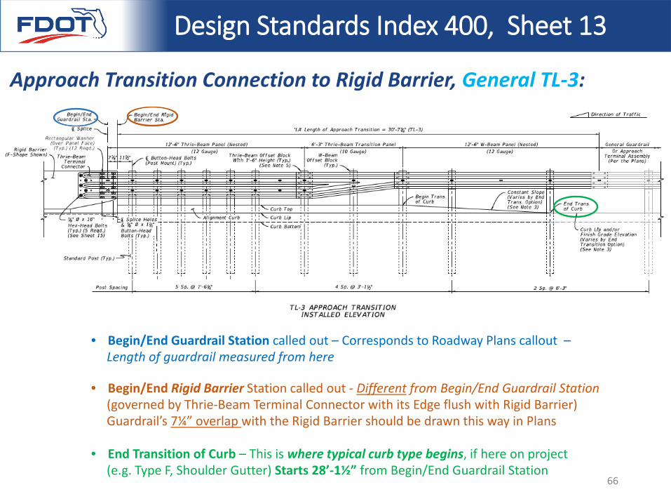
Design Standards Index 400, Sheet 13
Approach Transition Connection to Rigid Barrier, General TL-3:
• Begin/End Guardrail Station called out – Corresponds to Roadway Plans callout –Length of guardrail measured from here
• Begin/End Rigid Barrier Station called out - Different from Begin/End Guardrail Station (governed by Thrie-Beam Terminal Connector with its Edge flush with Rigid Barrier) Guardrail’s 7¼” overlap with the Rigid Barrier should be drawn this way in Plans
• End Transition of Curb – This is where typical curb type begins, if here on project (e.g. Type F, Shoulder Gutter) Starts 28’-1½” from Begin/End Guardrail Station
66
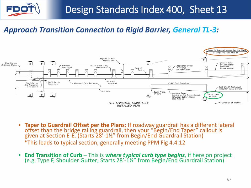
Design Standards Index 400, Sheet 13
Approach Transition Connection to Rigid Barrier, General TL-3:
• Taper to Guardrail Offset per the Plans: If roadway guardrail has a different lateral offset than the bridge railing guardrail, then your “Begin/End Taper” callout is given at Section E-E. (Starts 28’-1½” from Begin/End Guardrail Station) *This leads to typical section, generally meeting PPM Fig 4.4.12
• End Transition of Curb – This is where typical curb type begins, if here on project (e.g. Type F, Shoulder Gutter; Starts 28’-1½” from Begin/End Guardrail Station)
67
Design Standards Index 400, Sheet 14
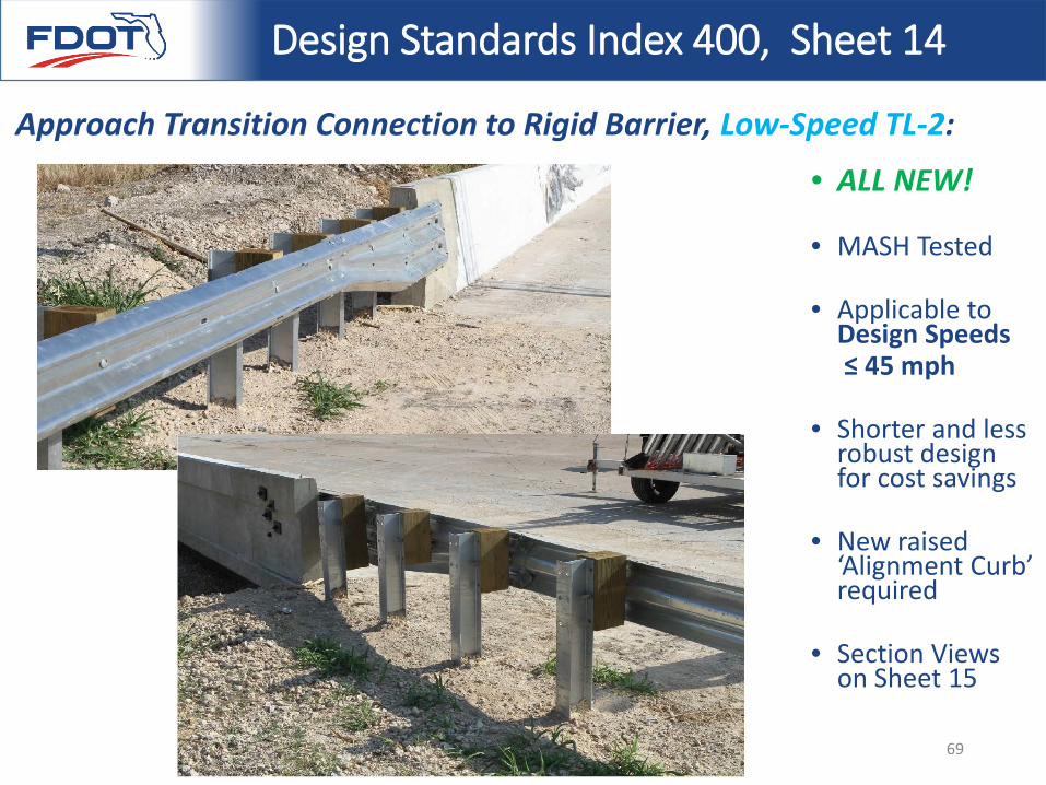
Approach Transition Connection to Rigid Barrier, Low-Speed TL-2:
• ALL NEW!
• MASH Tested
• Applicable to Design Speeds ≤ 45 mph
• Shorter and less robust design for cost savings
• New raised ‘Alignment Curb’ required
• Section Views on Sheet 15
68
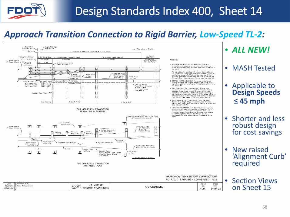
Design Standards Index 400, Sheet 14
Approach Transition Connection to Rigid Barrier, Low-Speed TL-2:
• ALL NEW!
• MASH Tested
• Applicable to Design Speeds ≤ 45 mph
• Shorter and less robust design for cost savings
• New raised ‘Alignment Curb’ required
• Section Views on Sheet 15
69
Design Standards Index 400, Sheet 15
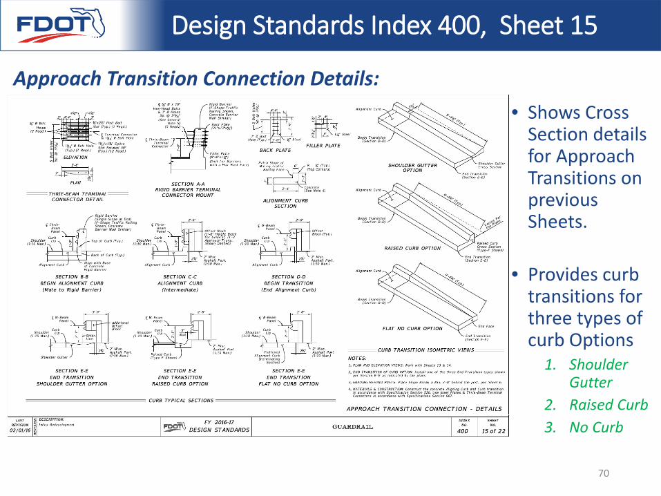
Approach Transition Connection Details:• Shows Cross
Section details for Approach Transitions on previous Sheets.
• Provides curb transitions for three types of curb Options
1. Shoulder Gutter
2. Raised Curb3. No Curb
70
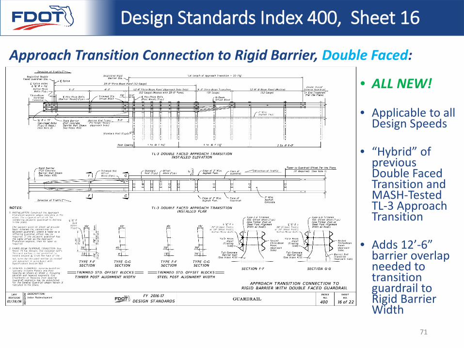
Design Standards Index 400, Sheet 16
Approach Transition Connection to Rigid Barrier, Double Faced:
• ALL NEW!
• Applicable to all Design Speeds
• “Hybrid” of previous Double Faced Transition and MASH-Tested TL-3 Approach Transition
• Adds 12’-6” barrier overlap needed to transition guardrail to Rigid Barrier Width
71
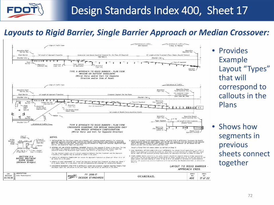
Design Standards Index 400, Sheet 17
Layouts to Rigid Barrier, Single Barrier Approach or Median Crossover:
• Provides Example Layout “Types” that will correspond to callouts in the Plans
• Shows how segments in previous sheets connect together
72
Design Standards Index 400, Sheet 17
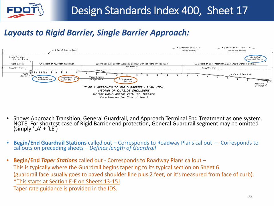
Layouts to Rigid Barrier, Single Barrier Approach:
• Shows Approach Transition, General Guardrail, and Approach Terminal End Treatment as one system. NOTE: For shortest case of Rigid Barrier end protection, General Guardrail segment may be omitted (simply ‘LA’ + ‘LE’)
• Begin/End Guardrail Stations called out – Corresponds to Roadway Plans callout – Corresponds to callouts on preceding sheets – Defines length of Guardrail
• Begin/End Taper Stations called out - Corresponds to Roadway Plans callout –This is typically where the Guardrail begins tapering to its typical section on Sheet 6 (guardrail face usually goes to paved shoulder line plus 2 feet, or it’s measured from face of curb). *This starts at Section E-E on Sheets 13-15! Taper rate guidance is provided in the IDS.
73
Design Standards Index 400, Sheet 17
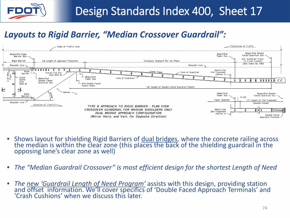
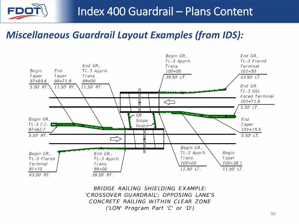
Layouts to Rigid Barrier, “Median Crossover Guardrail”:
• Shows layout for shielding Rigid Barriers of dual bridges, where the concrete railing across the median is within the clear zone (this places the back of the shielding guardrail in the opposing lane’s clear zone as well)
• The “Median Guardrail Crossover” is most efficient design for the shortest Length of Need
• The new ‘Guardrail Length of Need Program’ assists with this design, providing station and offset information. We’ll cover specifics of ‘Double Faced Approach Terminals’ and ‘Crash Cushions’ when we discuss this later.
74
Design Standards Index 400, Sheet 17
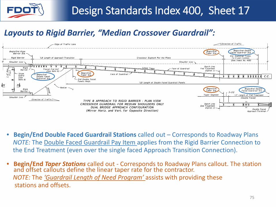
Layouts to Rigid Barrier, “Median Crossover Guardrail”:
• Begin/End Double Faced Guardrail Stations called out – Corresponds to Roadway PlansNOTE: The Double Faced Guardrail Pay Item applies from the Rigid Barrier Connection to the End Treatment (even over the single faced Approach Transition Connection).
• Begin/End Taper Stations called out - Corresponds to Roadway Plans callout. The station and offset callouts define the linear taper rate for the contractor. NOTE: The ‘Guardrail Length of Need Program’ assists with providing these stations and offsets.
75
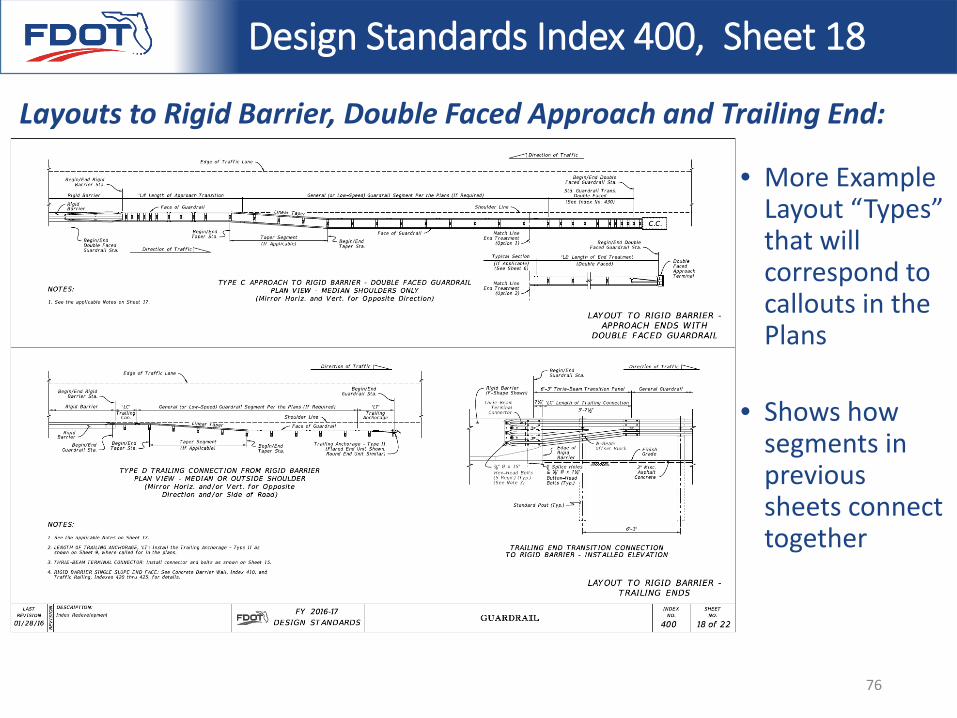
Design Standards Index 400, Sheet 18
Layouts to Rigid Barrier, Double Faced Approach and Trailing End:
• More Example Layout “Types” that will correspond to callouts in the Plans
• Shows how segments in previous sheets connect together
76
Design Standards Index 400, Sheet 19
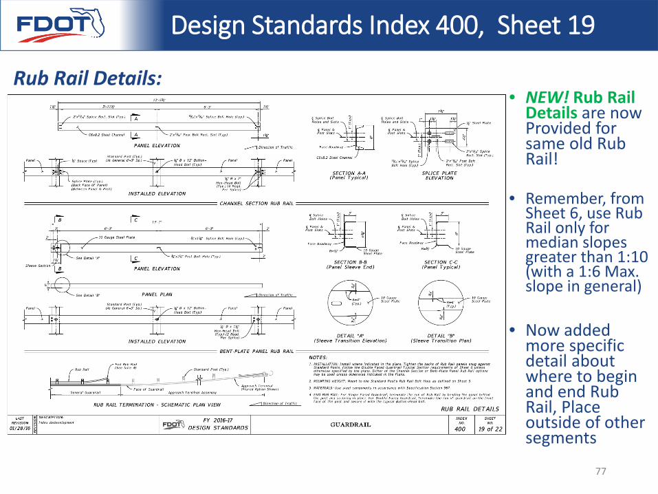
Rub Rail Details:• NEW! Rub Rail
Details are now Provided for same old Rub Rail!
• Remember, from Sheet 6, use Rub Rail only for median slopes greater than 1:10 (with a 1:6 Max. slope in general)
• Now added more specific detail about where to begin and end Rub Rail, Place outside of other segments
77
Design Standards Index 400, Sheet 20
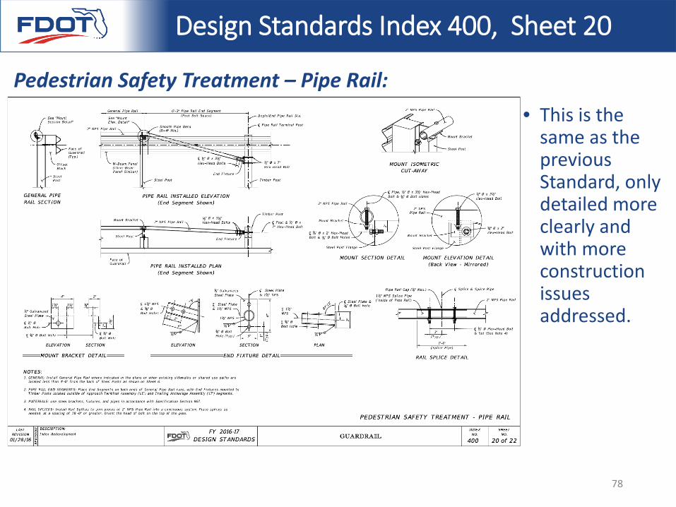
Pedestrian Safety Treatment – Pipe Rail:• This is the
same as the previous Standard, only detailed more clearly and with more construction issues addressed.
78
Design Standards Index 400, Sheet 21
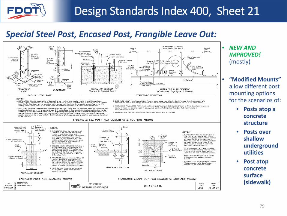
Special Steel Post, Encased Post, Frangible Leave Out:• NEW AND
IMPROVED! (mostly)
• “Modified Mounts” allow different post mounting options for the scenarios of:
• Posts atop a concrete structure
• Posts over shallow underground utilities
• Post atop concrete surface (sidewalk)
79
Design Standards Index 400, Sheet 22
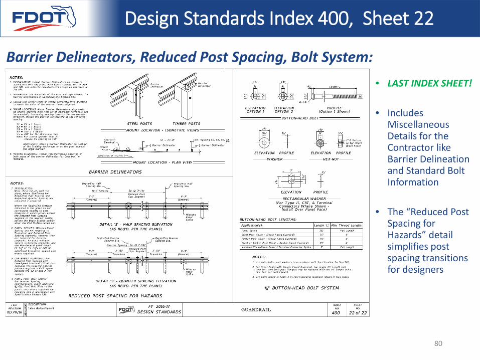
Barrier Delineators, Reduced Post Spacing, Bolt System:• LAST INDEX SHEET!
• Includes Miscellaneous Details for the Contractor like Barrier Delineation and Standard Bolt Information
• The “Reduced Post Spacing for Hazards” detail simplifies post spacing transitions for designers
80
Design Standards Index 400, Sheet 22
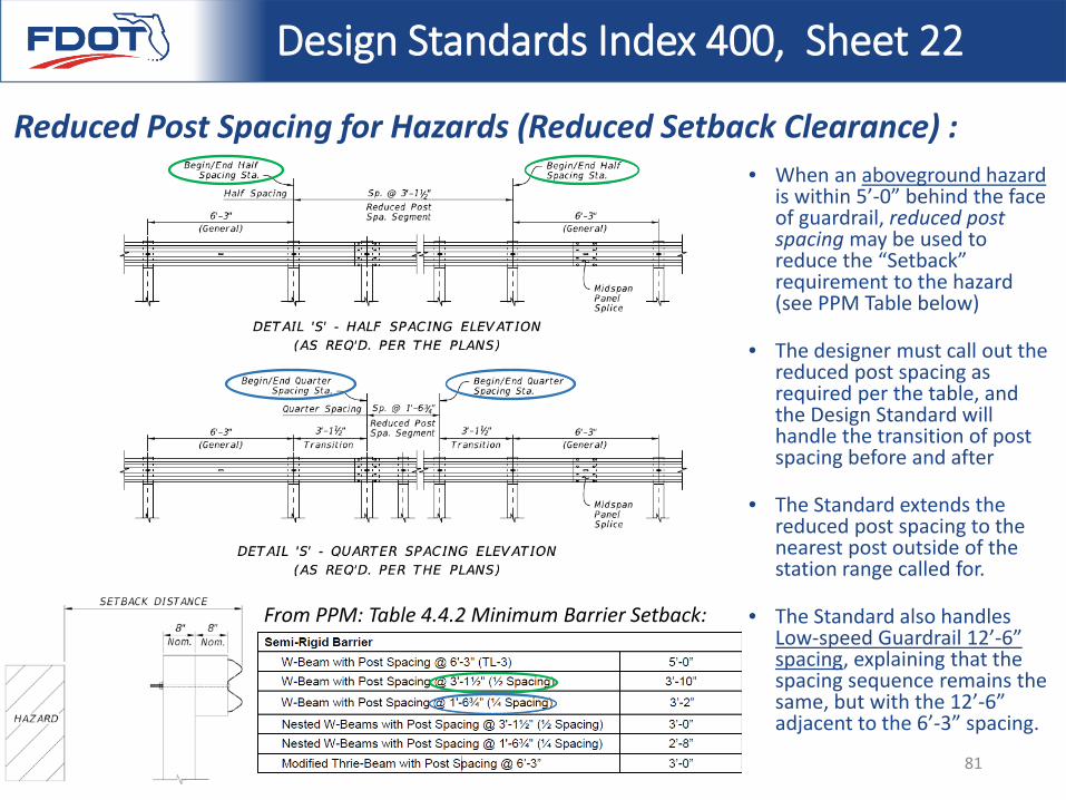
Reduced Post Spacing for Hazards (Reduced Setback Clearance) :• When an aboveground hazard
is within 5’-0” behind the face of guardrail, reduced post spacing may be used to reduce the “Setback” requirement to the hazard (see PPM Table below)
• The designer must call out the reduced post spacing as required per the table, and the Design Standard will handle the transition of post spacing before and after
• The Standard extends the reduced post spacing to the nearest post outside of the station range called for.
• The Standard also handles Low-speed Guardrail 12’-6” spacing, explaining that the spacing sequence remains the same, but with the 12’-6” adjacent to the 6’-3” spacing.
From PPM: Table 4.4.2 Minimum Barrier Setback:
81
Index 400 Guardrail – IDS
BEGIN PART 3: Instructions for Design Standards (IDS)
Index 400 is a DSR, as of February 1, 2016 82
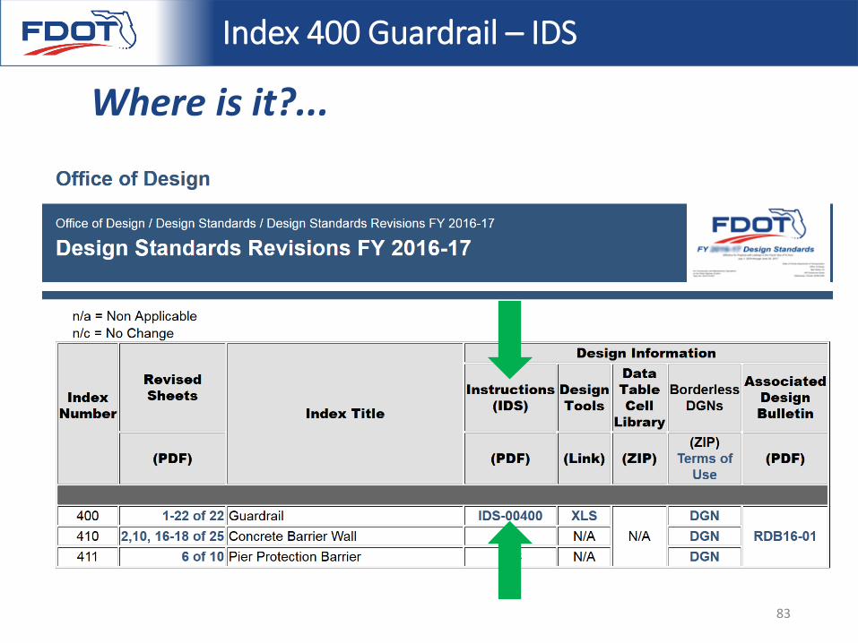
Index 400 Guardrail – IDS
Where is it?...
83
Index 400 Guardrail – IDS Part B
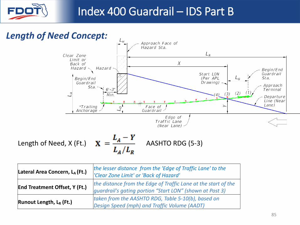
Length of Need Concept:
Length of Need (LON) is the length of guardrail required to provide a degree of shielding to prevent errant vehicles from impacting roadside hazards – measured from the hazard’s approach face to the approach end of the redirective guardrail segment.
From the Guardrail-LON program:“The standard method of determining guardrail placement for shielding hazards is based on the ‘Runout Length’ and the ‘Length of Need’ calculation in the AASHTO Roadside Design Guide (RDG), 4th Edition”
A picture is worth a thousand words, so….
84
Index 400 Guardrail – IDS Part B
Length of Need, X (Ft.) AASHTO RDG (5-3)
Lateral Area Concern, LA (Ft.) the lesser distance from the 'Edge of Traffic Lane' to the 'Clear Zone Limit' or 'Back of Hazard'
End Treatment Offset, Y (Ft.) the distance from the Edge of Traffic Lane at the start of the guardrail's gating portion “Start LON” (shown at Post 3)
Runout Length, LR (Ft.) taken from the AASHTO RDG, Table 5-10(b), based on Design Speed (mph) and Traffic Volume (AADT)
Length of Need Concept:
85
Index 400 Guardrail – IDS Part B
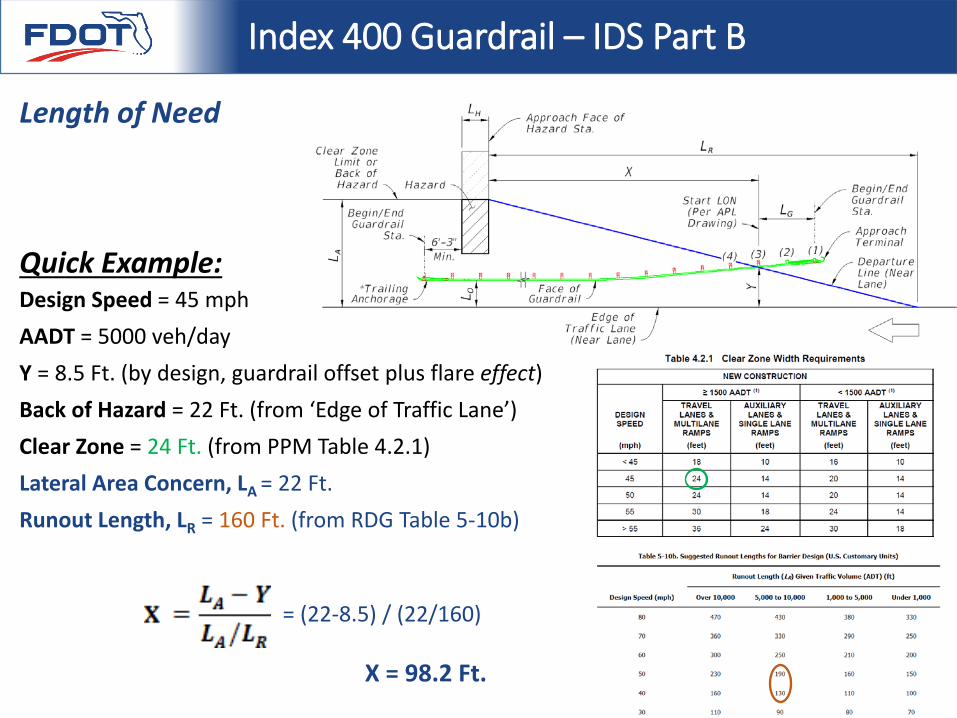
Design Speed = 45 mphAADT = 5000 veh/dayY = 8.5 Ft. (by design, guardrail offset plus flare effect)Back of Hazard = 22 Ft. (from ‘Edge of Traffic Lane’)Clear Zone = 24 Ft. (from PPM Table 4.2.1)Lateral Area Concern, LA = 22 Ft. Runout Length, LR = 160 Ft. (from RDG Table 5-10b)
= (22-8.5) / (22/160)
X = 98.2 Ft.
Length of Need
Quick Example:
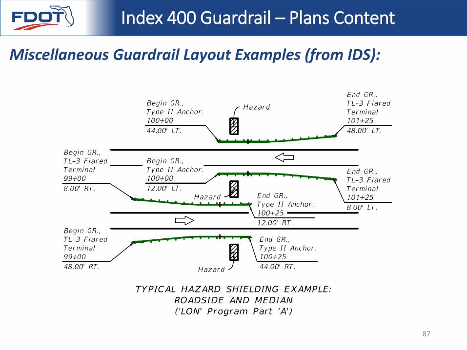
Index 400 Guardrail – Plans Content
Miscellaneous Guardrail Layout Examples (from IDS):
87
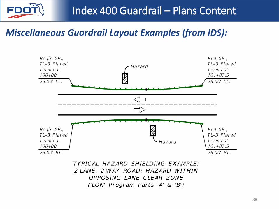
Index 400 Guardrail – Plans Content
Miscellaneous Guardrail Layout Examples (from IDS):
88
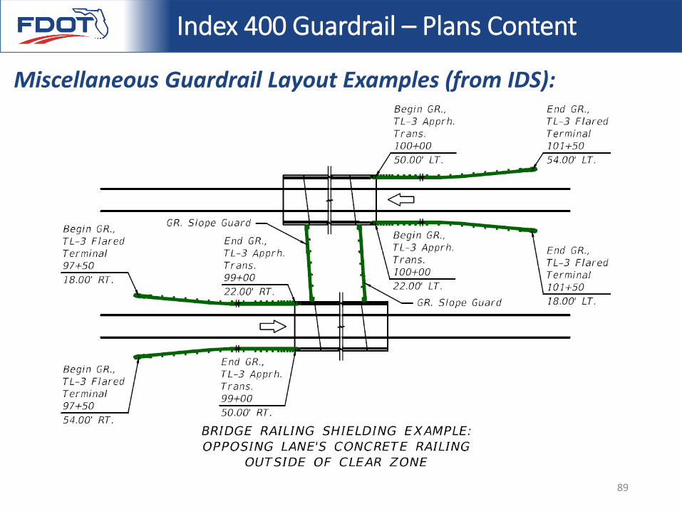
Index 400 Guardrail – Plans Content
Miscellaneous Guardrail Layout Examples (from IDS):
89
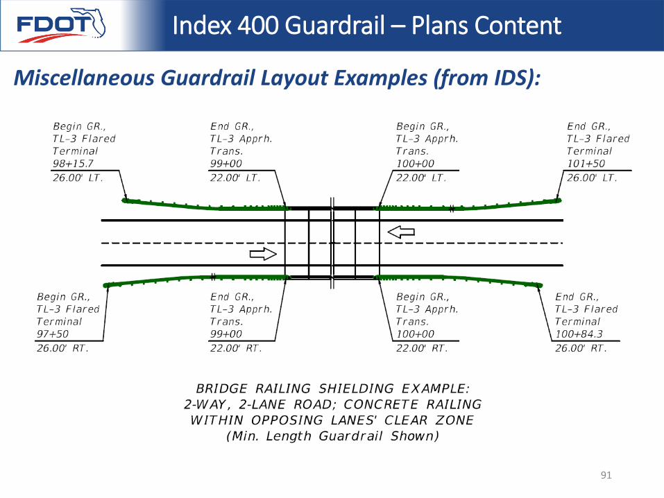
Index 400 Guardrail – Plans Content
Miscellaneous Guardrail Layout Examples (from IDS):
90
Index 400 Guardrail – Plans Content
Miscellaneous Guardrail Layout Examples (from IDS):
91
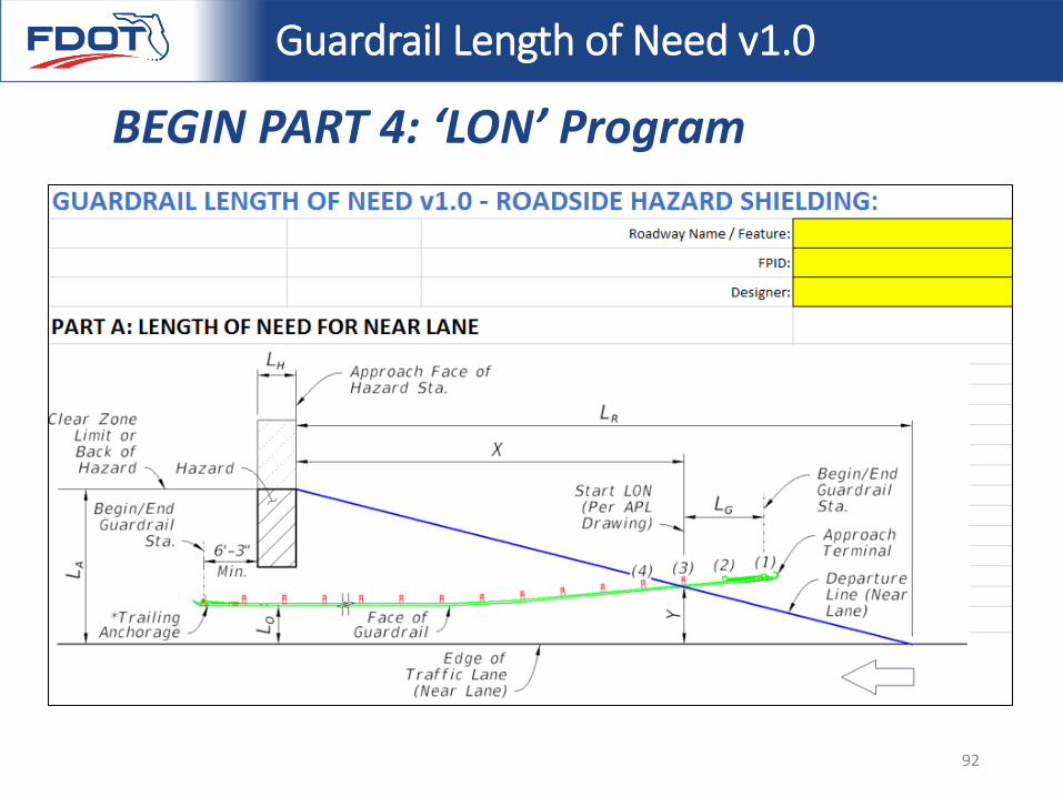
Guardrail Length of Need v1.0
BEGIN PART 4: ‘LON’ Program
92
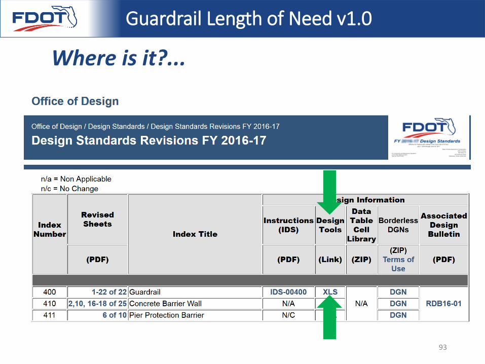
Guardrail Length of Need v1.0
Where is it?...
93
Guardrail Length of Need v1.0
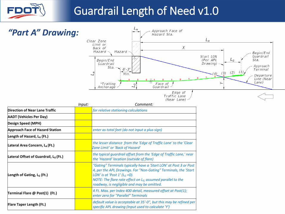
“Part A” Drawing:
Input: Comment:Direction of Near Lane Traffic for relative stationing calculations
AADT (Vehicles Per Day)
Design Speed (MPH)
Approach Face of Hazard Station enter as total feet (do not input a plus sign)
Length of Hazard, LH (Ft.)
Lateral Area Concern, LA (Ft.) the lesser distance from the 'Edge of Traffic Lane' to the 'Clear Zone Limit' or 'Back of Hazard'
Lateral Offset of Guardrail, LO (Ft.) the typical guardrail offset from the 'Edge of Traffic Lane,' near the 'Hazard' location (outside of flare)
Length of Gating, LG (Ft.)
"Gating" Terminals typically have a 'Start LON' at Post 3 or Post 4, per the APL Drawings. For "Non-Gating" Terminals, the 'Start LON' is at 'Post 1' (LG =0). NOTE: The flare rate effect on LG, assumed parallel to the roadway, is negligible and may be omitted.
Terminal Flare @ Post(1) (Ft.) 4 Ft. Max. per Index 400 detail, measured offset at Post(1); enter zero for "Parallel" Terminals
Flare Taper Length (Ft.) default value is acceptable at 35'-0", but this may be refined per specific APL drawing (Input used to calculate 'Y')
Guardrail Length of Need v1.0
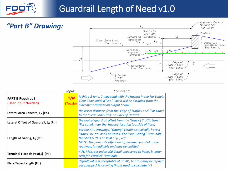
“Part B” Drawing:
Input: Comment:
PART B Required?(User Input Needed)
Y/N(Toggle)
Is this a 2-lane, 2-way road with the Hazard in the Far Lane's Clear Zone limit? If "No" Part B will be excluded from the placement calculation output below.
Lateral Area Concern, LA (Ft.) the lesser distance from the 'Edge of Traffic Lane' (Far Lane) to the 'Clear Zone Limit' or 'Back of Hazard'
Lateral Offset of Guardrail, LO (Ft.) the typical guardrail offset from the 'Edge of Traffic Lane' (Far Lane), near the 'Hazard' location (outside of flare)
Length of Gating, LG (Ft.)
per the APL Drawings, "Gating" Terminals typically have a 'Start LON' at Post 3 or Post 4. For "Non-Gating" Terminals, the Start LON is at 'Post 1' (LG =0). NOTE: The flare rate effect on Lg, assumed parallel to the roadway, is negligible and may be omitted.
Terminal Flare @ Post(1) (Ft.) 4 Ft. Max. per Index 400 detail; measured to Post(1); enter zero for 'Parallel' Terminals
Flare Taper Length (Ft.) default value is acceptable at 35'-0", but this may be refined per specific APL drawing (Input used to calculate 'Y')
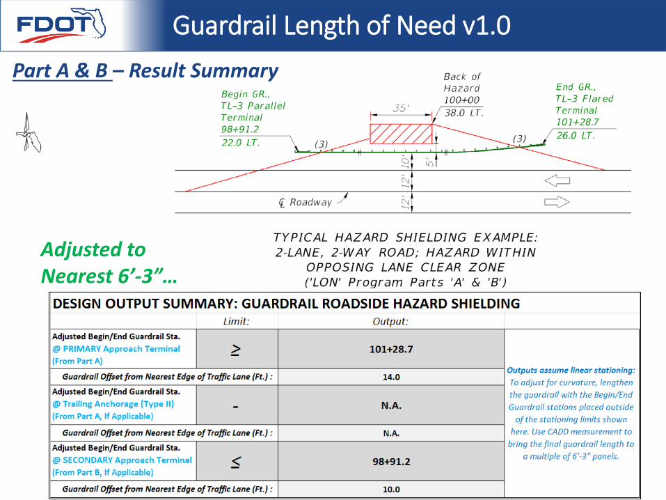
Guardrail Length of Need v1.0Part A & B – Result Summary
Adjusted to Nearest 6’-3”…
Guardrail Length of Need v1.0
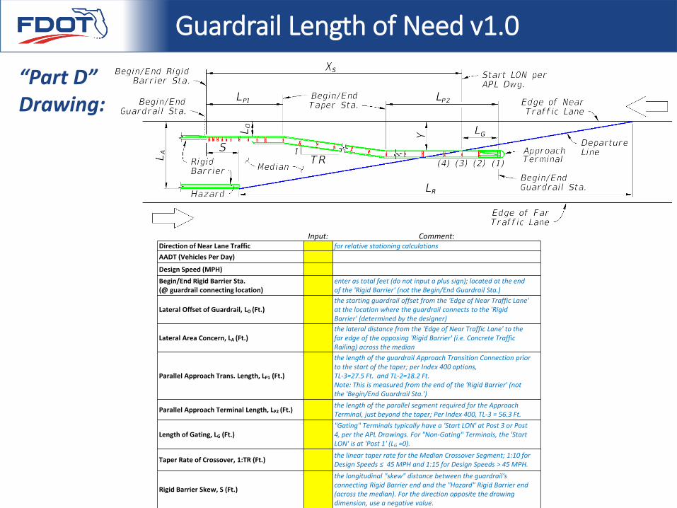
“Part D” Drawing:
Input: Comment:Direction of Near Lane Traffic for relative stationing calculationsAADT (Vehicles Per Day)
Design Speed (MPH)Begin/End Rigid Barrier Sta. (@ guardrail connecting location)
enter as total feet (do not input a plus sign); located at the end of the 'Rigid Barrier' (not the Begin/End Guardrail Sta.)
Lateral Offset of Guardrail, LO (Ft.)the starting guardrail offset from the 'Edge of Near Traffic Lane' at the location where the guardrail connects to the 'Rigid Barrier' (determined by the designer)
Lateral Area Concern, LA (Ft.)the lateral distance from the 'Edge of Near Traffic Lane' to the far edge of the opposing 'Rigid Barrier' (i.e. Concrete Traffic Railing) across the median
Parallel Approach Trans. Length, LP1 (Ft.)
the length of the guardrail Approach Transition Connection prior to the start of the taper; per Index 400 options, TL-3=27.5 Ft. and TL-2=18.2 Ft.Note: This is measured from the end of the 'Rigid Barrier' (not the 'Begin/End Guardrail Sta.')
Parallel Approach Terminal Length, LP2 (Ft.) the length of the parallel segment required for the Approach Terminal, just beyond the taper; Per Index 400, TL-3 = 56.3 Ft.
Length of Gating, LG (Ft.)"Gating" Terminals typically have a 'Start LON' at Post 3 or Post 4, per the APL Drawings. For "Non-Gating" Terminals, the 'Start LON' is at 'Post 1' (LG =0).
Taper Rate of Crossover, 1:TR (Ft.) the linear taper rate for the Median Crossover Segment; 1:10 for Design Speeds ≤ 45 MPH and 1:15 for Design Speeds > 45 MPH.
Rigid Barrier Skew, S (Ft.)
the longitudinal "skew" distance between the guardrail's connecting Rigid Barrier end and the "Hazard" Rigid Barrier end (across the median). For the direction opposite the drawing dimension, use a negative value.
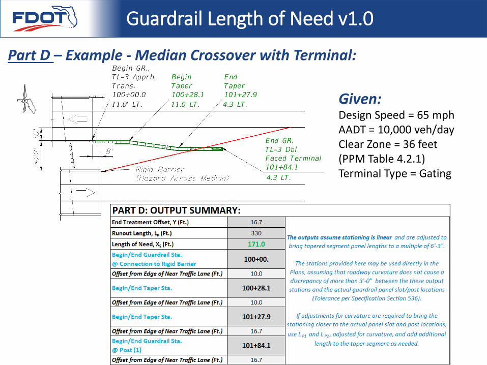
Guardrail Length of Need v1.0
Design Speed = 65 mphAADT = 10,000 veh/dayClear Zone = 36 feet (PPM Table 4.2.1)Terminal Type = Gating
Part D – Example - Median Crossover with Terminal:
Given:
Design Standards Index 400 - Guardrail
BEGIN PART 5: Where to Find More Comprehensive Training:
• By the End of May, a 6 hour design webinar will be placed here…http://www.dot.state.fl.us/rddesign/Training/Webinar16/Pres16.shtm
99
Design Standards Index 400 - Guardrail
For all future FDOT Roadway Design Training, sign up to receive notification e-mails at… http://www.dot.state.fl.us/projectmanagementoffice/ContactDatabase.shtm
(Google “FDOT Contact Mailer”)
100
Design Standards Index 400 - Guardrail
THANK YOU!
QUESTIONS?
For more information:[email protected]@dot.state.fl.us