fcc special technologies workpackage
TRANSCRIPT

FCC Special Technologies Workpackage
Task 11: Radiation Hardness AssuranceStatus Report April 2017
http://indico.cern.ch/event/558539/
Giulio Borghello, Markus Brugger, Mar Capeans, Francesco Cerutti, Salvatore Danzeca, Federico Faccio, Ruben Garcia Alia, Georgi Gorine, Angelo Infantino ,
Michael Moll, Federico Ravotti
26 April 2017 M.Brugger & M.Capeans 2

FCC Special Technologies WPTask 11 Radiation Hardness Assurance
• RHA consists of all activities undertaken to ensure that the electronics and materials developed for FCC perform to their design specifications after exposure to the FCC radiation environment.
• RHA deals with environment definition, part selection, part testing, radiation tolerant design, and FCC subsystems requirements.
• TASK 1 Field conditions and radiation levels at FCC
• TASK 2 FCC Qualification Protocols, evaluation of test facilities
• TASK 3 Equipment needs for the accelerator, particle detectors and service systems; strategies for RHA taking into account maintenance, reliability and remote operation
• TASK 4 State of the art and development efforts on radhard components for HL-LHC (assuring continuity: evaluation of HL-LHC VS FCC needs, identify common VSs specific developments).
• TASK 5 New Technologies: developments linked to technologies: wireless communication, miniaturization, optical transmission, compactness, on-chip optical/electrical, packaging, new materials…
26 April 2017 3M.Brugger & M.Capeans

Tasks & Deliverables (Oct’15 – Dec’18)
26 April 2017 M.Brugger & M.Capeans 4
FCC Task 11 Deliverables Month By end of Status WHO
TASK 1 Field conditions and radiation levels at FCC
D1-1. Evaluation of FLUKA models’ needs (environment and effects) M6 Mar’16 ✓ MB, AI
D1-2. FLUKA tuning for FCC (operational/layout options/requirements)
M12 Sep’16 ✓ MB, AI
D1-3. Agreement on FCC target radiation field/levels M14 Nov’16 ✓ MB, RG
TASK 2 FCC Qualification Protocols
D2-1. Define overall FCC qualification requirements as input to RHA
M12 Sep’16 ongoing All
D2-2. Evaluation of current irradiation facilities and testing infrastructure
M20 May’17 ongoing FR, GG
TASK 3 Equipment needs for the accelerator, detectors, service systems
D3-1. Identification of technologies used at FCC with their expected radiation levels M14 Nov’16 starting All
D3-2. Catalogue of critical equipment (technology, supplier, function, etc.)
M18 Mar’17 starting All
TASK 4 Development efforts on radhardcomponents for HL-LHC
D4.1 Evaluate HL-LHC VS FCC needs of rad hard components
M20 May’17 ongoing All
TASK 5 New Technologies D5.1 Prototype status and definition of developments linked to technologies
M20 May’17ongoing
All
D5.2 Radiation tester of advanced components/systems M36 Sep’18 ongoing MB, SDD5.3 Radiation sensor M40 Jan’19 ongoing FR, GG

RHA Resources - Personnel
26 April 2017 M.Brugger & M.Capeans 5
Category Budget (PM)
Committed Available
Fellow 30 24 A.Infantino EN-STI (from 1/2/16) 6
Doctoral 60 36 G.Gorine EP-DT (from 1/11/15)24 G.Borghello EP-ESE (from 1/8/16)
0
PJAS 30 6 m (1/1/16 – 30/7/16) 23
CERN personnel at 5-10% level:
EN Dept: M.Brugger, S.Danzeca, R.Garcia Alia, F.Cerutti, A.Lechner EP Dept: F.Faccio, F.Ravotti, G.Pezzulo, M.Moll TE Dept: M.Capeans
Many links to other FCC WPs and R2E
Intention:11m PJAS + R2E contribution12m extension Borghello
6m extension Infantino
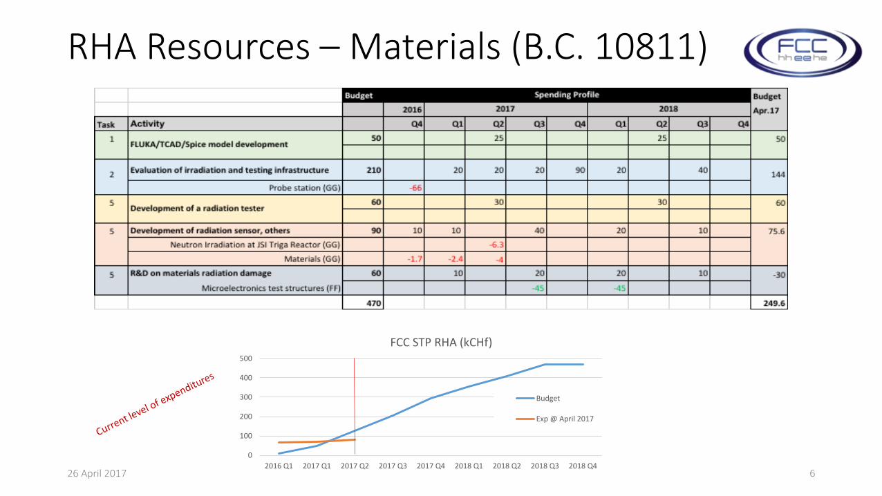
RHA Resources – Materials (B.C. 10811)
26 April 2017 M.Brugger & M.Capeans 6
0
100
200
300
400
500
2016 Q1 2017 Q1 2017 Q2 2017 Q3 2017 Q4 2018 Q1 2018 Q2 2018 Q3 2018 Q4
FCC STP RHA (kCHf)
Budget
Exp @ April 2017
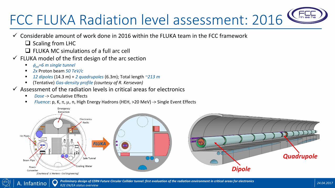
FCC FLUKA Radiation level assessment: 2016
A. Infantino 24.04.2017Preliminary design of CERN Future Circular Collider tunnel: first evaluation of the radiation environment in critical areas for electronicsR2E EN/EA status overview
Considerable amount of work done in 2016 within the FLUKA team in the FCC framework Scaling from LHC FLUKA MC simulations of a full arc cell
FLUKA model of the first design of the arc section int=6 m single tunnel 2x Proton beam 50 TeV/c 12 dipoles (14.3 m) + 2 quadrupoles (6.3m); Total length ~213 m (Tentative) Gas-density profile (courtesy of R. Kersevan)
Assessment of the radiation levels in critical areas for electronics Dose -> Cumulative Effects Fluence: p, K, p, m, n, High Energy Hadrons (HEH, >20 MeV) -> Single Event Effects
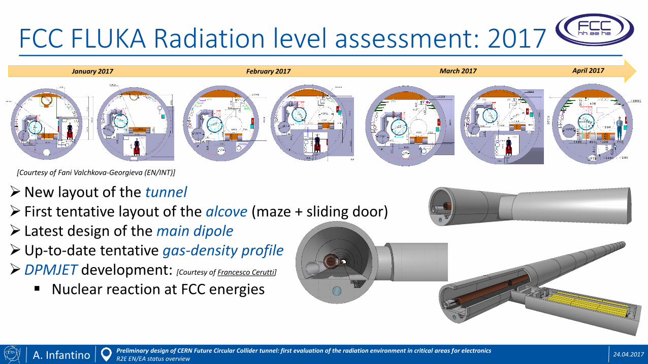
FCC FLUKA Radiation level assessment: 2017
A. Infantino 24.04.2017Preliminary design of CERN Future Circular Collider tunnel: first evaluation of the radiation environment in critical areas for electronicsR2E EN/EA status overview
New layout of the tunnel First tentative layout of the alcove (maze + sliding door) Latest design of the main dipoleUp-to-date tentative gas-density profileDPMJET development: [Courtesy of Francesco Cerutti]
Nuclear reaction at FCC energies
[Courtesy of Fani Valchkova-Georgieva (EN/INT)]
January 2017 February 2017 March 2017 April 2017
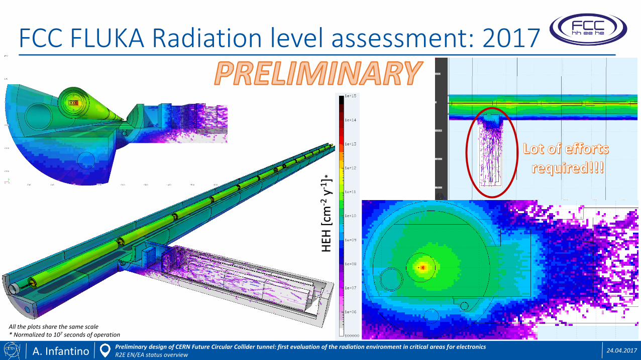
FCC FLUKA Radiation level assessment: 2017
A. Infantino 24.04.2017Preliminary design of CERN Future Circular Collider tunnel: first evaluation of the radiation environment in critical areas for electronicsR2E EN/EA status overview
All the plots share the same scale* Normalized to 107 seconds of operation
HEH
[cm
-2y-1
]*

Tasks 2 & 3: Qualification & Protocols & Equipment needs
Defining first rough qualification levels• Tunnel (FCC as compared to HL-LHC): close to beamline and adjacent, missing: high-loss locations (e.g,
collimators, etc.) -> scaling most likely similar as for the tunnel
• Equipment availability: impact on the qualification requirements of components/systemsStarting from a general 'maximum' and 'relative' unavailability possibly to be tolerated by R2E
maximum: 10% of unavailability -> thus defining test/qualification constraints
Defining RHA strategy for new developments and known equipment/system changes (R.Garcia Alia):
• ’Frozen' tunnel design - first radiation level 'matrix' for typical tunnel section (in very good agreement with original estimate based on 'first principles')
• The approach is that we'll face a LHC-like situation with similar equipment groups
• Knowledge on existing ‘inventories’ from the LHC and discuss what will most likely have to remain in radiation areas or relocated into safe places: critical equipment inventory and availability implications
• Showing that for a COTS-based design we hit a boundary with the current qualification procedure and available testing facilities
26 April 2017 M.Brugger & M.Capeans 10

Tasks 2 & 3: Qualification & Protocols & Equipment needs
Evaluating specs of irradiation facilities for FCC and test infrastructure:
• Irradiation Facilities DB: http://irradiation-facilities.web.cern.ch
• MGy dosimetry (F.Ravotti, G.Gorine)• Analysis of state-of-the-art technologies for radiation measurement
• Study of existent RADMON sensors at LHC, development for FCC
• Design, realization, and testing of an innovative dosimetry solution for ultra-high fluences
• High-speed Readout for mixed-field irradiations (S.Danzeca)• Collaboration between EN-STI, BE-BI, EP-DT
• First test this year in CHARM
26 April 2017 M.Brugger & M.Capeans 11
FCC-RADMON Vacuum Transistor (VFET)

Tasks 4&5: Technologies
Strategy
• Impossible to know technology in 20+ years, but we can study concepts relevant for future strategies as redundancy/qualification can likely be ported to future technologies, facilitating design choices.
• We study and develop building blocks of multiple high-end solutions.
26 April 2017 M.Brugger & M.Capeans 12

Technology Demonstrators
• Communication links (S.Danzeca)
• Ethernet- based FPGA/PHY solution similar for the fibre based solution (GBTX and VTTx) combined with FPGA/ASIC design
• Fiber-optic based: Basic building blocks taking as an example the GBTxCERN development
• Wireless solutions, 'early R&D’: gathering necessary requirements for a wireless network structure and specifications, focus on assessing possible induced failures due to the radiation
26 April 2017 M.Brugger & M.Capeans
Core
Speed 10-100Mbit/s up to 1Gbit/s
Speed 5-10Gb/s (>10Gb/s)
Client layer
Speed (Wifi) ~1Gb/s

Technology Demonstrators
• Deep submicron CMOS technologies (F.Faccio, G.Borghello)
26 April 2017 M.Brugger & M.Capeans
q The technology currently used in the LHC experiments is the 250nm.
130and65nm
250nm(1997)
28nm
qWe are mainly studying the 65nm technology, that has been proposedfor the new pixel detectors used in the HL-HLC and we started toinvestigate the radiation response of 28nm MOS technology.
q LHC upgrades will increase the Total Radiation Dose that detectors anddevices have to withstand.
q The technology node isdefined by the minimumchannel length (L).
q Irradiation strongly affect CMOS 65nm performances.
q In HL-LHC pixels of innerlayer will be exposed atTID = 1Grad in 10years.
q At 1Grad the 65nmtechnology shows anextreme degradation ofits main parameters.
65nmtechnologyexposedtoaTID=1Grad
65nmpMOS∆� ≅ 100%
• The study of 65nm radiation-hardness is at an advanced stage. Confirmed strong dependency on irradiation, and unexpected dose rate dependence (lower dose ~ larger degradation) and understood the physical processes
• The firsts experiment at 28nm MOS show also large parameters degradation
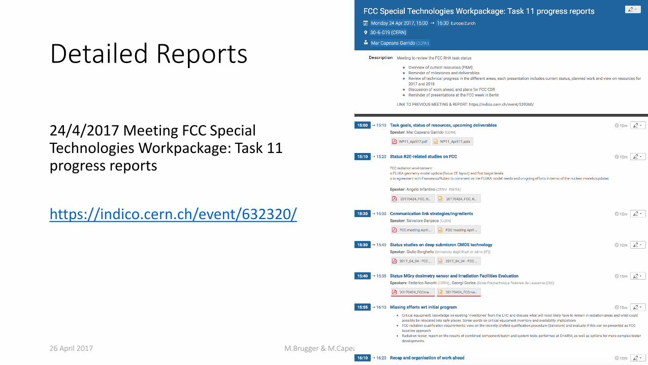
Detailed Reports
24/4/2017 Meeting FCC Special Technologies Workpackage: Task 11 progress reports
https://indico.cern.ch/event/632320/
26 April 2017 M.Brugger & M.Capeans 15
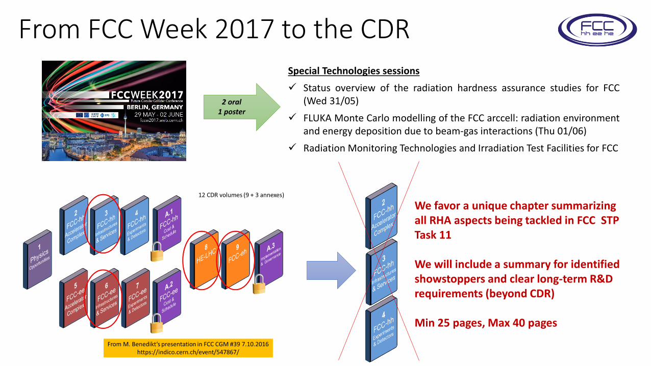
From FCC Week 2017 to the CDRSpecial Technologies sessions
Status overview of the radiation hardness assurance studies for FCC(Wed 31/05)
FLUKA Monte Carlo modelling of the FCC arccell: radiation environmentand energy deposition due to beam-gas interactions (Thu 01/06)
Radiation Monitoring Technologies and Irradiation Test Facilities for FCC
2 oral1 poster
We favor a unique chapter summarizing all RHA aspects being tackled in FCC STP Task 11
We will include a summary for identified showstoppers and clear long-term R&D requirements (beyond CDR)
Min 25 pages, Max 40 pages

SPARES
26 April 2017 M.Brugger & M.Capeans 17

General R2E/availability considerations
A. Infantino 24.04.2017Preliminary design of CERN Future Circular Collider tunnel: first evaluation of the radiation environment in critical areas for electronicsR2E EN/EA status overview
• Integrated luminosity target: 20 ab-1 in 3.5 yr periods of 5 ab-1 (1.5 yr longshutdown)
• Burn-off is expected to be extreme, with stable beams lasting ~3h
• Therefore, turnaround time needs to be very small: best reasonablyachievable is ~3h (~50% maximum efficiency), thus need to minimize R2Edowntime Injector availability will therefore be crucial (LHC or superconducting SPS)
“Availability studies for FCC”, Arto Niemi
• Availability working group: accelerator unavailability (failure rate times recovery time) budget will be given by system
• A part of this unavailability will be allocated to R2E (roughly 10% but to be studied per system)
to then be translated to target failures per unit luminosity and respective target system cross sections throughradiation levels
Critical points: system-level testing approach, no guidelines/standards available (link with RADSAGA trainingnetwork), redundancy
[Courtesy of Ruben Garcia Alia]

Integration of R2E with the different WG
A. Infantino 24.04.2017Preliminary design of CERN Future Circular Collider tunnel: first evaluation of the radiation environment in critical areas for electronicsR2E EN/EA status overview
Work fully integrated in the FLUKA team of EN/STI where additional resources (Ilaria Besana, Fellow) are specificallydedicated to different FCC studies, in particular concerning lifetime assessment for detector components.
Strong presence in the Infrastructure & Operation and Integration WG
Collaborations across many different groups Daniel Schoerling (TE-MSC), Barbara Caiffi (INFN) -> Magnets Volker Mertens (TE), Fani Valchkova-Georgieva (EN-ACE-INT ) -> Civil Engineering Design, Integration Valentina Venturi (TE-MSC-CMI) -> Cryostat design Roberto Kersevan (TE-VSC-VSM), Ignasi Bellafont (TE-VSC-VSM) -> Gas-density profile, beam screen design Davide Bozzini (EN-EL-DDO), Maria Mylona (EN-EL-DDO) -> Electrical requirements Andrea Apollonio (TE-MPE-PE) -> Availability Ahmed Bannour (IT-CS-TR) -> Data transmission requirements Cedric Garion (TE-VSC-DLM) -> Beam screen design Barbara Dalena (BE-ABP-HSS) -> Beam optics Markus Widorski (HSE-RP-AS) -> RP-related
FCC Task 11: activities progress reports 20
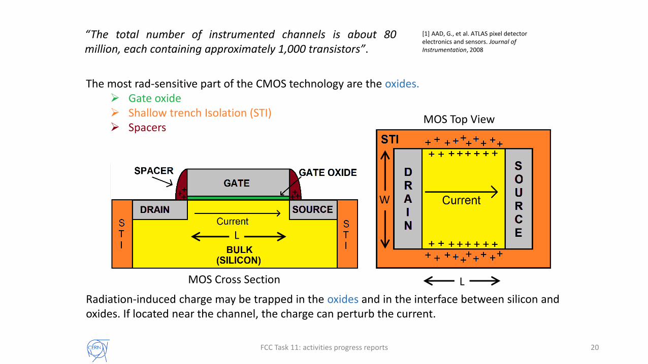
The most rad-sensitive part of the CMOS technology are the oxides. Gate oxide Shallow trench Isolation (STI) Spacers
MOS Cross Section
MOS Top View
L
L
W
Radiation-induced charge may be trapped in the oxides and in the interface between silicon and oxides. If located near the channel, the charge can perturb the current.
“The total number of instrumented channels is about 80million, each containing approximately 1,000 transistors”.
[1] AAD, G., et al. ATLAS pixel detector electronics and sensors. Journal of Instrumentation, 2008
FCC Task 11: activities progress reports 21
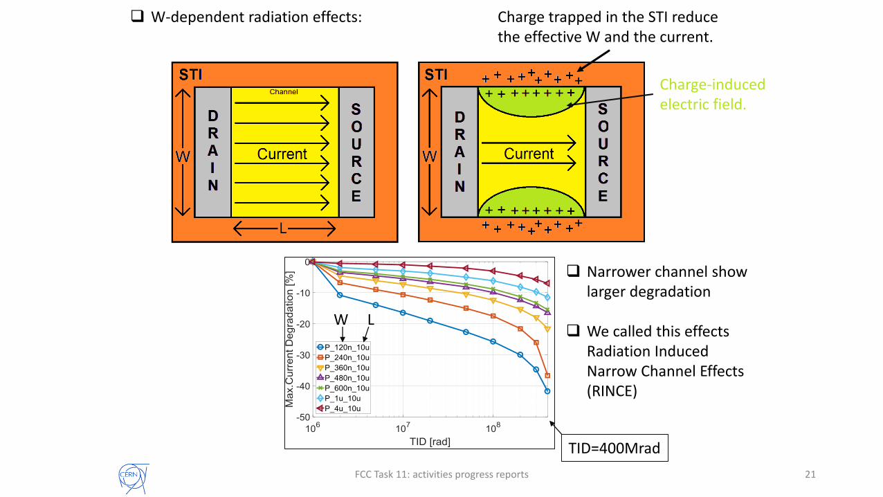
Charge trapped in the STI reduce the effective W and the current.
Charge-induced electric field.
W L
TID=400Mrad
Narrower channel show larger degradation
We called this effects Radiation Induced Narrow Channel Effects (RINCE)
W-dependent radiation effects:

FCC Task 11: activities progress reports 22
L-dependent radiation effects (not trivial): The degradation of the current strongly depend on
temperature and on applied electric field.
Large and unexpected further degradation when high temperature and polarization are applied to an irradiated device.
During irradiation: The charge trapped in the spacers
increase the series resistance. During annealing:
Charge moves into the gate oxides, increasing the threshold voltage.
Last point taken at T=25°CCharge trapped in the
spacers during irradiation.
Trapped charges move into the gate oxide, interfering with the current flowing in the channel.
FCC Task 11: activities progress reports
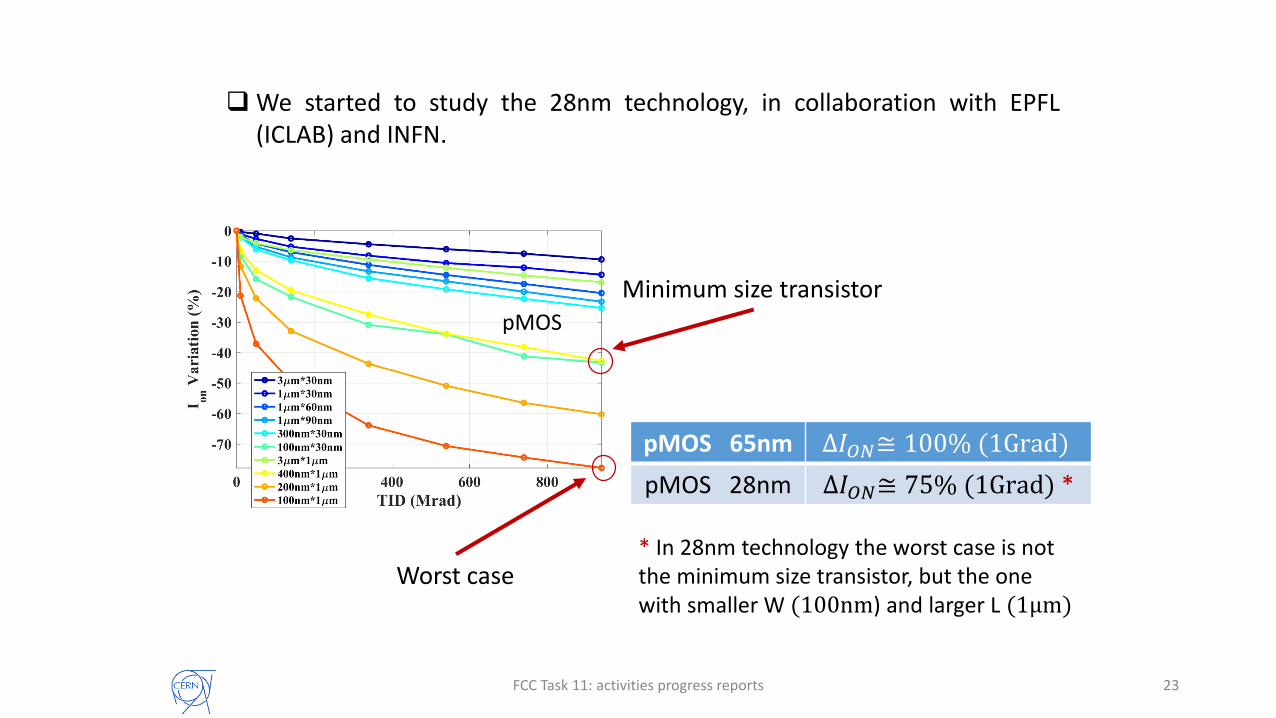
pMOS
* In 28nm technology the worst case is not the minimum size transistor, but the one with smaller W (100nm) and larger L (1μm)
23
We started to study the 28nm technology, in collaboration with EPFL(ICLAB) and INFN.
pMOS 65nm ∆𝐼𝑂𝑁≅ 100% (1Grad)
pMOS 28nm ∆𝐼𝑂𝑁≅ 75% (1Grad) *
Minimum size transistor
Worst case

Dosimetry
26 April 2017 M.Brugger & M.Capeans 24
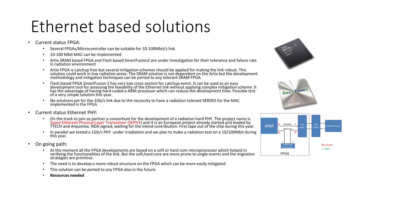
Ethernet based solutions• Current status FPGA:
• Several FPGAs/Microcontroller can be suitable for 10-100Mbit/s link.
• 10-100 Mbit MAC can be implemented
• Artix SRAM based FPGA and Flash based SmartFusion2 are under investigation for their tolerance and failure rate in radiation environment
• Artix FPGA is Latchup free but several mitigation schemes should be applied for making the link robust. This solution could work in low radiation areas. The SRAM solution is not dependent on the Artix but the development methodology and mitigation techniques can be ported to any tolerant SRAM FPGA.
• Flash based FPGA SmartFusion 2 has very low cross section for Latchup event. It can be used as an easy development tool for assessing the feasibility of the Ethernet link without applying complex mitigation scheme. It has the advantage of having hard-coded a ARM processor which can reduce the development time. Possible test of a very simple solution this year.
• No solutions yet for the 1Gb/s link due to the necessity to have a radiation tolerant SERDES for the MAC implemented in the FPGA
• Current status Ethernet PHY:• On the track to join as partner a consortium for the development of a radiation hard PHY. The project name is
Space Ethernet Physical Layer Transceiver (SEPHY) and it is an European project already started and leaded by TTECH and Arquimea. NDA signed, waiting for the inkind contribution. First tape out of the chip during this year.
• In parallel we tested a 1Gb/s PHY under irradiation and we plan to make a radiation test on a 10/100Mbit during this year.
• On going path:• At the moment all the FPGA developments are based on a soft or hard core microprocessor which helped in
verifying the functionalities of the link. But the soft,hard core are more prone to single events and the migration strategies are primitive.
• The need is to develop a more robust structure on the FPGA which can be more easily mitigated
• This solution can be ported to any FPGA also in the future.
• Resources needed
ARM

Fiber Optic based solutions
• Fiber optic solution advantages:• Speed 5-10Gb/s (>10Gb/s)
• Possible to cover very long distances (km)
• Slow control signalling possible
• Audio/video communication possible
• The topology of the network can be only point to point. The daisy chain is possible but two links should be implemented on the same card
• Basic building blocks taking as an example the GBTx CERN development
S.Danzeca - Planning and strategy for HL-LHC R2E

Ethernet based solutions
• Current status Transceiver:• GBTX 4.8 Gb/s Transceiver developed by EP is implemented in several boards and can
be used as a baseline for all the developments. Long term support. RadHard by design• New version of GBTX for HL currently under development
• Current status Small Form Factor (SFP) Transceiver:• VTTx is a RadHard by design physical layer developed by EP• Current version provided by EP is multimode but a single mode is being developed for
the accelerator sector thanks to a collaboration between EP and BE.
• Current status FPGA/ASIC:• Scalable Sensor Data Processor (SSDP) is a mixed-signal ASIC DSP processor
• The design and development of the SSDP is an activity stemming from the European Space Agency and is supported by a consortium lead by Thales Alenia Space.
• We are including in the SSDP the e-link interface with which we will be able to talk with the GBTX and have a RadHard by design DSP processor
• On going path:• At the moment the SSDP need a followup with the activities that Thales is going to do
on the prototype. • First it will be necessary a verification of the inclusion of the elink in the design. • Then the SSDP should be tested in our environment with in mind some intense
computing application• Resource needed