fcc compliance statement for american users
TRANSCRIPT


FCC COMPLIANCE STATEMENTFOR AMERICAN USERS
This equipment generates and uses radio frequency energy and if not installed and used prop-erly, that is, in strict accordance with the manufacturer’s instructions, may cause interferenceto radio and television reception. It has been type tested and found to comply with the limitsfor a Class B computing device in accordance with the specifications in Subpart J of part 15 ofFCC Rules, which are designed to provide reasonable protection against such interference in aresidential installation. However, there is no guarantee that interference will not occur in aparticular installation. If this equipment does cause interference to radio or television recep-tion, which can be determined by turning the equipment off and on, the user is encouraged totry to correct the interference by one or more of the following measures:
— Reorient the receiving antenna— Relocate the printer with respect to the receiver— Plug the printer into a different outlet so that the printer and receiver are on different
branch circuits.
If necessary, the user should consult the dealer or an experienced radio/television technicianfor additional suggestions. The user may find the following booklet prepared by the FederalCommunications Commission helpful:
“How to Identify and Resolve Radio-TV Interference Problems.”
This booklet is available from the U.S. Government Printing Office, Washington, DC 20402.Stock No. 004-000-0345-4.
W A R N I N G
The connection of a non-shielded printer interface cable to this printer will invalidate the FCCCertification of this device and may cause interference levels which exceed the limits estab-lished by the FCC for this equipment. If this equipment has more than one interface connec-tor, do not leave cables connected to unused interfaces.
All rights reserved. No part of this publication may be reproduced, stored in a retrieval system, ortransmitted, in any form or by any means, mechanical, photocopying, recording or otherwise,without the prior written permission of Seiko Epson Corporation. No patent liability is assumedwith respect to the use of the information contained herein. While every precaution has been takenin the preparation of this book, Seiko Epson Corporation assumes no responsibility for errors oromissions. Neither is any liability assumed for damages resulting from the use of the informationcontained herein.
Graphics created with UniPaint by Unison World Inc. and EPSON 3D-Graph.
Apple is a registered trademark of Apple Computer, Inc.Centronics is a registered trademark of Centronics Data Computer Corporation.Epson is a registered trademark of Seiko Epson Corporation.IBM is a registered trademark of International Business Machines Corporation.Microsoft is a trademark of Microsoft Corporation.ESC/P is a registered trademark of Seiko Epson Corporation.
Copyright © 1986 by Seiko Epson CorporationNagano, Japan
i i

Contents
Introduction2 About This Manual
Chapter 1Setting Up Your FX Printer1-1 Unpacking Your Printer1-2 Selecting the Right Location1-3 Installing the Ribbon1-6 Loading Continuous-feed Paper1-12 Turning On the Printer1-12 Operating the Control Panel1-14 SelecType1-16 Running the Self Test1-17 Connecting the Printer to Your Computer1-18 Choosing the Operating Mode with DIP Switches
Chapter 2Choosing and Loading Paper2-1 Choosing Paper2-1 Using Single-sheet Paper2-6 Reinstalling the Tractor Unit2-8 The Paper Thickness Lever
Chapter 3Using the FX with Application Programs3-1 Printer Selection Menus3-2 Computer -Printer Communication3-3 Word Processors3-4 Spreadsheets3-6 Graphics Programs3-6 Programming Languages
Contents i i i

Chapter 4FX Printer Features4-1 Quality and Fonts4-2 Print Size and Character Width4-2 Pitches and Proportional Spacing4-3 Special Effects and Emphasis4-4 Using Different Character Sets4-5 Page Layout and Other Commands
Chapter 5Graphics and User-defined Characters5-2 The Print Head5-3 Pin Labels5-4 Graphics Commands5-6 Simple Graphics Programming5-8 Density Varieties5-10 Designing Your Own Graphics5-13 User-defined Characters
Appendix ACommand SummaryA-4 Commands in Numerical OrderA-7 Epson (ESC/P) CommandsA-36 IBM Printer Emulation Mode Commands
Appendix BCharacter TablesEl Epson ModeB-9 Epson International Character SetsB-11 IBM Printer Emulation Mode
Appendix CProblem Solving and MaintenanceC-1 General TroubleshootingC-3 Troubleshooting Graphics ProblemsC-3 Data Dump ModeC-4 IBM PC BASIC SolutionsC-5 Maintaining Your PrinterC-7 Transporting the Printer
iv Contents

Appendix DDefaults and DIP SwitchesD-1 Default and Initialization SettingsD-2 DIP Switch SettingsD-3 International Character Sets
Appendix EChoosing and Setting Up Optional InterfacesE-1 Compatible InterfacesE-2 Choosing an InterfaceE-3 Installing an InterfaceE-6 Inserting the Interface boardE-7 Serial Interface Settings
Appendix FTechnical SpecificationsF-1 PrintingF-1 PaperF-2 MechanicalF-2 ElectricalF-3 EnvironmentF-3 Parallel InterfaceF-5 Data Transfer Sequence
Index
Contents v

Introduction
The FX-86e and FX-286e printers combine all the well-known virtuesof previous Epson 9-pin printers with many features normally exclusiveto costly 24-pin printers.
l The speed of draft printing is 240 characters per second in draft eliteand 200 in draft pica. When you have perfected a document, youcan switch to one of two Near Letter Quality fonts-Roman orSans Serif.
Draf t pr in t ing is ext remely fast .NLQ Roman is clear and typewriter-like.N L Q S a n s S e r i f i s c r i s p a n d d i s t i n c t i v e .
l The SelecType feature gives you access to Near Letter Quality(NLQ) and condensed print. All you have to do is press the buttonfor the style you want. While the FX is printing, the SelecType panelshows you what choices it’s using.
l If you are using software designed for an IBM@ printer, you have thechoice of using the FX in Epson mode or IBM printer emulationmode. Even better, you can combine the best of both worlds; thepowerful Epson mode commands can now print character graphicslike those used by IBM printers and computers.
l Loading paper is now easier than ever. Single sheets can be loadedby just moving a lever, and the tractor lets you load a wide range ofwidths of continuous-feed paper, including labels.
l For headings and other emphasis, you can use double-high anddouble-wide printing.
Introduction 1

About this Manual
To make it easier to set up your new FX-86e or FX-286e, this manualincludes a lo-step guide. This guide, which is printed on the inside ofthe back flap, summarizes the first chapter’s setting up instructions.
Chapters 2 through 5 cover the basic and advanced functions, andthe appendixes contain reference information, including all the detailsyou need to use any of the printer’s commands, and some advice onsolving problems.
Finally, there is a comprehensive index, and inside the back of themanual is a pull-out quick reference card containing the informationyou need most.
2 Introduction

Chapter 1
Setting Up Your FX Printer
Setting up your new FX is easy. Simply follow the steps in thischapter.
NoteThe FX-86e and FX-286e are basically the same printer except that theFX-286e can accept wider paper. Therefore, the illustrations in thismanual show only the FX-86e.
1 Unpacking Your Printer
First, remove the printer from the box and take off all outside plasticcovering and foam supports. Make sure you have received all the partsshown in the illustration below.
Figure 1-1Printer parts
Setting Up Your FX Printer 1-1

Tilt the tractor cover up and remove the two foam pads underneathit. (These pads protect the tractor unit during shipping; be sure to savethem.)
WARNINGThe printer is protected by a print head protector, a platenprotector and two locking tabs during shipping. These protectiveitems must be removed before you turn on the printer. Follow thesteps below Figure 1-2.
Also, you should install the paper feed knob. To install the knob,simply push it onto the shaft on the right side of the printer asshown in Figure 1-2.
1. Remove the left locking tab.
2. Remove the print head protector.
3. Move the print head to the left.
4. Remove the right locking tab and the platen protector.
2 Selecting the Right Location
The most important consideration in choosing a location for yourprinter is that it be close enough to connect a cable to your computer.But also keep the following tips in mind:
1-2 Setting Up Your FX Printer

l Place the printer or printer stand on a solid and level foundation.Avoid setting it on carpet or on unstable surfaces such as chairs.
l Use a grounded outlet-one that has three holes to match the powerplug on the printer. Don’t use an adapter plug.
l Avoid using electrical outlets that are controlled by wall switches. Ifyou accidentally turn off a switch, you could wipe out valuableinformation and stop your printing.
l Keep your printer and computer away from base units for cordlesstelephones.
l Avoid using an outlet on the same circuit breaker with largeelectrical machines or appliances that might disrupt the flow ofpower to your printer.
l Choose a place that is clean and away from moisture, dust, andexcessive heat (such as a heater or direct sunlight).
If you are going to use continuous-feed paper, clear enough spacearound the printer so that the paper has an unobstructed path in andout of the printer. There are three common methods of arranging aprinter and continuous paper:
l Using a printer stand with the paper stacked underneath it.
l Using a desk or table as a stand, with the printer near the rear edgeand the paper on the floor or on a shelf.
l Putting the printer on a desk or table and stacking the paper behindthe printer.
3 Installing the Ribbon
To install the ribbon, follow the directions below:
1. Remove the tractor cover that comes installed on the printer. Toremove it, simply pull the back of the cover toward you until thecover is vertical. Then lift it up and off the printer.
2. Manually move the print head to the middle of the platen.
Setting Up Your FX Printer 1-3

WARNINGThe power must be OFF when you move the print head. Moving theprint head when the power is ON may damage your printer. If you’vebeen using your printer just before changing the ribbon cartridge, becareful not to touch the print head because it becomes hot during use.
3. before installing the ribbon cartridge, turn the small knob on top inthe direction of the arrow to tighten the ribbon as shown in Figure 1-3.
Figure 1-3Tightening the ribbon
4. For the FX-86e, hold the ribbon cartridge by the raised plastic finon top of the cartridge; for the FX-286e hold the cartridge by thetwo plastic tabs. Lower the cartridge into the printer, guiding thetwo pins on each end of the cartridge into the slots in the printerframe, as shown in Figure 1-4. Press firmly on each end of thecartridge to make sure the pins are firmly seated in the slots.
5. Now use the point of a pencil to guide the ribbon into place be-tween the ribbon guide and the print head as shown in Figure 1-5.(There is also a diagram on the top of the ribbon cartridge itself.)
6. With the cartridge in place, again turn the ribbon knob in thedirection of the arrow to tighten the ribbon.
And that’s it-the ribbon is now installed.
1-4 Setting Up Your FX Printer

Figure 1-4.Installing the ribbon cartridge
Figure 1-5.Positioning the ribbon
Setting Up Your FX Printer 1-5

4 Loading Continuous-feed Paper
When you receive your FX, it is set up to print on continuous-feedpaper. If you plan to use single-sheet paper, turn to Chapter 2 forinstructions on setting up the printer for single sheets. If you havebought the optional automatic sheet feeder, complete the remainder ofthe setup steps before you install the automatic sheet feeder (which hasits own manual).
The FX tractor units are adjustable to accommodate different widthsof paper-from 4 to 10 inches on the FX-86e and from 4 to 16 inches onthe FX-286e. Before you load continuous-feed paper, prepare the printerin the following manner:
1. Make sure the printer is turned off.
2. Remove the tractor cover that comes installed on the printer. Toremove it, simply pull the back of the cover toward you until it isvertical. Then lift the cover up and off the printer.
3. Install the paper rest as shown in Figure 1-6. This part helps preventthe paper from catching on the printer cable.
1-6 Setting Up Your FX Printer

Figure 1-6.Installing the paper rest
4. Pull both the paper release lever and the paper bail lever toward thefront of the printer. (Figure 1-6 shows where these levers are.)
Setting Up Your FX Printer 1-7

Now you are ready to load the continuous-feed paper. Just follow thesteps below:
1. Using Figure 1-7 as a guide, pull the locking levers on thepin-feed holders forward so that you can move the holders tothe left and right.
Figure 1-7.Pin-feed locking levers
2. Move the left holder so that the locking lever is about 1/4 inchfrom the left side and push the locking lever back to lock thatholder in place. Leave the right holder unlocked.
3. Open the pin-feed covers as shown in Figure 1-8.
WARNINGDo not use the pin-feed covers to move the pin-feed holders.
1-8 Setting Up Your FX Printer

Figure 1-8.Open pin-feed cover
4. Guide the paper into the paper slot, and push it through until itcomes up between the ribbon guide and the platen. (Moving thepaper with a side-to-side motion makes it easier to push the paperthrough.)
5. Pull the paper up until the top is above the pin-feed holders. Fit theholes on the left side of the paper over the pins in the left holder (asshown in Figure 1-9) and close the cover.
Figure 1-9.Fitting the paper over the pin feeds
Setting Up Your FX Printer 1-9

6. Fit the right side of the paper into the right holder, moving theholder as needed to match the width of the paper.
7. Close the right cover, making sure the paper has no dips or wrinklesand lock the right holder in place.
Now that you have loaded the continuous-feed paper, prepare theprinter for printing.
1. Push the paper bail lever back.
2. Hold the paper guide above the printer with the edge tab on theleft. Insert the right hinge tab into the right tab slot, as shown inFigure 1-10. Then insert the left tab into the left slot and pushthe guide back so that it is horizontal.
Figure 1-10
This guide keeps paper that is coming out of the printer frominterfering with the paper going in. The guide is also used in theupright position for printing on single sheets of paper.
1-10 Setting Up Your FX Printer

3. With the printer turned OFF, advance the paper with the paperfeed knob on the right side of the printer until the first row ofperforations is about even with the top of the ribbon. (SeeFigure 1-1 1.)
Figure 1-11.Setting top of form
This is the top of form position. It makes your printed pages endwhere you want them to and prevents the printer from printing on theperforations. The paper should be in this position when the power isturned on or when software initializes the printer or sets the pagelength.
4. Replace the tractor cover.
Setting Up Your FX Printer 1-11

5 Turning On the Printer
Before plugging in the power cord, see that the power switch nearthe back of the left side of the printer is turned off; then plug thepower cord into a properly grounded socket.
WARNINGBefore turning on the printer, be absolutely sure you have removed allpacking materials. Turning on the printer when the print head cannotmove may seriously damage the mechanism.
Now, turn the power ON with the switch on the left side of theprinter. When you turn on the printer, three things happen:
l The print head moves back and forth and stops at the left side of theprinter; this is the home position.
l The printer is initialized and set to certain default settings (which arefully described in Appendix D).
l The green power light on the control panel comes on.
6 Operating the Control Panel
The control pane! is shown in Figure 1-12.
Figure 1-12.The FX control panel.
1.12 Setting Up Your FX Printer

The three buttons nearest the front of the printer control advancingthe paper and communication with the computer. The four indicatorlights show when the printer is turned on and when it is ready to use.
The buttons
There are three large buttons on the control panel.
OFF LINE/ON LINE
The green light next to this button indicates thatthe printer is able to receive and print data fromthe computer. When the light is off, the printer isoff line and cannot receive any data. Press thebutton to change from on line to off line or fromoff line to on line. The printer automatically goesoff line when you try to print without paper inthe printer. Pressing the button then has noeffect until you load paper.
FORM FEED/ROMAN
When the printer is off line, this button ejects asingle sheet of paper or advances continuouspaper to the next top of form.When the printer is on line and in NLQ mode,pressing the button selects the Roman font.
LINE FEED/SANS SERIF
When the printer is off line, this buttonadvances the paper one line each time you pressit or continuously if you hold it down. Whenthe printer is turned on, use this button toadvance paper.When the printer is on line and in NLQ mode,pressing the button selects the Sans Serif font.
NoteUse the paper feed knob on the right side of the printer only when theprinter is turned OFF Using it when the printer is on can damage theprinter mechanism.
The indicator lights
In addition to the ON LINE light, the printer has three other lights.
POWER This comes on to show that the printer isconnected to the power and is turned on.
READY This comes on when the printer is on line andready to print. It normally flickers duringprinting.
Setting Up Your FX Printer 1-13

PAPER OUT This comes on when the printer is out of paper.
Also on the control panel are two touch switches that let you choosethe print style and size. These are the SelecType buttons, which aredescribed in the next section.
7 SelecType
The SelecType feature consists of two buttons on the control panel.These buttons select the most used printing features-Near LetterQuality (NLQ) and condensed.
With the two SelecType buttons, you can produce any of the fourtypestyles shown below:
NLQ can also be condensed for more characters on a line.
Draft is for fast printing and NLQ for higher-quality work. In thecondensed mode all characters are about 60% of their normal width.
Two NLQ fonts are available: Roman and Sans Serif. You selectthem by using the FORM FEED and LINE FEED buttons while theprinter is on line. The FORM FEED button selects Roman, and theLINE FEED button selects Sans Serif, A software command to changethe NLQ typeface is also available in the Epson mode.
NLQ Roman is clear and typewriter-like.NLQ Sans Serif is cr i sp and dis t inc t ive .
If you want NLQ printing, simply press the NLQ button. If you wantcondensed printing, simply press the CONDENSED button.
When you press either SelecType button, it beeps twice and itsorange indicator light turns on to show that you have selected it. If you
1.14 Setting Up Your FX Printer

want to turn off either mode, press its button again. It beeps once andthe indicator light turns off to show that the mode is cancelled.
As you can see, SelecType makes it easy to choose either NLQ orcondensed, and the indicator lights always tell you which modes you’veselected.
Trying out SelecType is a simple three-step process:
1. Create a short sample document or file with your favoriteapplication program.
2. Press either or both of the SelecType buttons.
3. Print the document or file using your application program’s printcommand.
If SelecType Does Not WorkSome applications programs are designed to control all typestyle
functions. Before each printing operation, these programs cancel allprevious typestyle settings by sending a signal (INIT) or by sendingspecific control codes to cancel certain typestyles. These signals orcontrol codes may cancel your SelecType settings.
One reset signal, however, does not affect your SelecType settings.This is the ESC @ command.
You can see whether your program is changing your settings bywatching the buttons when printing starts. If the lights change, theprogram is controlling the typestyles.
If your application program changes your SelecType settings, youhave two choices:
1. Use the program’s setup procedure (which could be called byanother name, such as install) to remove the codes that interferewith your SelecType settings.
2. Use the print control codes for your application program instead ofSelecType to control your printing. Most programs that cancelSelecType settings also have sophisticated print control commandsthat give the same results that SelecType does. The manual for yourprogram should explain the necessary commands.
Setting Up Your FX Printer 1-15

NoteAlso remember that control codes in your document will override theSelecType settings. Therefore, if you have a code for NLQ in yourdocument and you press the DRAFT SelecType button, your printingwill still be in NLQ.
8 Running the Self Test
The FX has a built-in self test that prints out the characters in itsmemory so that you can see that the printer is working properly.
The self test also prints the settings of the printer’s DIP switches.You’ll use this part of the printout in the last section of this chapter.
Before running the self test, make sure that the power is OFF andpaper is loaded in the printer. (Use wide paper in the FX-286e to avoidprinting on the platen.)
To run the self test in the Near Letter Quality (NLQ) mode, holddown the FORM FEED button at the same time you turn the printer on.When the printing starts, release the FORM FEED button.
The self test first prints the version number of the printer and severallines of settings that are explained in the last section of this chapter.Then it prints the characters from its memory. The test continues untilyou turn the printer off. Part of a typical self test is shown below.
Character mode Normal 1-1 OFFShape of zero 0 (Unslashed) 1-2 OFFCG Table Italic6 1-3 OFFProtocol mode ESC/P 1-4 OFFPrint Quality Draft 1-5 OFFCountry U.S.A. 1-6 ON 1-7 ON 1-8 ONPage Length 11 inch 2-1 OFFCSF Mode Invalid 2-2 OFFSkip Perforation None 2-3 OFFAuto LF Depend on I/F 2-4 OFF!"#$%&'()*+,-./0123456789:;<=>?@ABCDEFGHIJKLMNOPQRSTUVWXYZ[
!"#$%&'()*+,-./0123456789:;<=>?@ABCDEFGHIJKLMNOPQRSTUVWXYZ[\"#$%&'()*+,1./0123456789:;<=>?@ABCDEFGHIJKLMNOPQRSTUVWXYZ[\]#$%&'()*+,-./0123456789:;<=>?@ABCDEFGHIJKLMNOPQRSTUVWXYZ[\]~$%&'()*+,-./0123456789:;<=>?@ABCDEFGHIJKLMNOPQRSTUVWXYZ[\]-%&'()*+,-./0123456789:;<=>?@ABCDEFGHIJKLMNOPQRSTUVWXYZ[\]!-.&'()*+,-./0123456789:;<=>?@ABCDEFGHIJKLMNOPQRSTUVWXYZ[\]-.a'()*+,-./0123456789:;<=>?@ABCDEFGHIJKLMNOPQRSTUVWXYZ[\]-.ab()*+,-./0123456789:;<=>?@ABCDEFGHIJKLMNOPQRSTUVWXYZ[\]~-.abc
1-16 Setting Up Your FX Printer

To run the same test in the draft mode, hold down the LINE FEEDbutton instead of the FORM FEED button while you turn the printer on.The FX cannot print a draft self test, however, if the NLQ DIP switch ison. Therefore, if the Print Quality line of the self test printout says NLQ,you cannot print a draft test without changing a DIP switch.
9 Connecting the Printer to Your Computer
Your FX printer communicates with your computer through aCentronics® compatible parallel interface. If your computer uses thistype of interface and you have a suitable cable, you can connect yourcomputer immediately. (Be sure that your cable is a shielded cable.)
If you do not know what kind of interface your computer requires,consult its manual or your dealer. For information on optionalinterfaces available from Epson, see Appendix E, and for furtherinformation on the standard interface, see Appendix F.
The parallel interfaceBefore connecting a parallel interface cable, see that both the printer
and computer are turned off. Then plug the connector into the printer.Next squeeze the clips gently and click them into place.
Some parallel cables have a ground wire. Connect this wire to theground screw on the printer to protect data from interference. Thenplug the other end of the cable into the computer and connect theground wire on the computer end of the cable if it has one.Figure 1-13 shows a properly connected parallel cable.
Figure 1-13.Connecting a parallel cable
Setting Up Your FX Printer 1-17

10 Choosing the Operating Mode with DIP Switches
The FX has 12 switches that allow you to change many of theprinter’s settings to suit your individual needs. You may need to changeone or two of them now. These switches, known as DIP (Dual In-linePackage) switches, are in the back of the printer. See Figure 1-14.
Figure 1-14.DIP switch location
The switches are in two groups and are numbered, as shown inFigure 1-14. As you can see in the example below, the first partof the self test shows the settings of the switches. You will findyour own self test printout helpful as you use this section.
Character mode Normal 1-1 OFFShape of zero 0 (Unslashed) 1-2 OFFCG Table Italics 1-3 OFFProtocol mode ESC/P 1-4 OFFPrint Quality Draft 1-5 OFFCountry U.S.A. 1-6 ON 1-7 ON 1-8 ONPage Length 11 inch 2-1 OFFCSF Node Invalid 2-2 OFFSkip Perforation None 2-3 OFFAuto LF Depend on I/F 2-4 OFF.!"#$%&'()*+,-./0123456789:;<=>?@ABCDBFGHIJKLMNOPQRSTUVWXYZ[!"#$%&'()*+,-./0123456789:; <=>?@ABCDEFGHIJKLMNOPQRSTUVWXYZ[\"#$%&'()*+,-./0123456789:;<=>?@ABCDEFGHIJKLMNOPQRSTUVWXYZ[\]#$%&'()*+,-./0123456789:;<=>?@ABCDEFGHIJKLMNOPQRSTUVWXYZ[\]~
1-18 Setting Up Your FX Printer

Before you change any DIP switch settings, turn the printer aroundto give you easy access to the switches. Then you can easily turn theswitches on and off with a thin pointed object, such as a smallscrewdriver or the cap of a ballpoint pen. The switches are ON whenthey are UP, and OFF when they are DOWN.
NoteWhen you change a DIP switch setting, turn off the power, reset theswitch or switches, then turn on the power again. The printer checksand recognizes new settings only at the time you turn the power on.
The operating mode
The FX has two operating modes, ESC/P® and IBM® printeremulation mode. ESC/P stands for Epson Standard Code for Printers,a powerful set of commands developed by Epson and supported byalmost all application software for personal computers. This is themode that you should find the most useful and valuable for yourprinting. The rest of this manual refers to the ESC/P mode simply asthe Epson mode.
The IBM printer emulation mode is for software that is designed onlyfor IBM printers. It is not necessary to use this mode for your FX to becompatible with IBM computers. As you can see from the list of Epsonand IBM printer emulation mode commands in Appendix A, theEpson mode has more commands and many more capabilities.
There are only two cases in which you may want to use the IBMprinter emulation mode:
1. Your software lists only IBM printers in its printer selection menu.
2. You need to use the following characters and your applicationsoftware will not print them in the Epson mode:
If you select IBM printer emulation mode with the DIP switch andchoose an IBM printer in your software’s printer selection menu, yourFX will behave as an IBM printer does. You can use most software thatsupports IBM printers, but you will notice that the commands do notallow you access to all the features of your Epson printer.
Setting Up Your FX Printer 1-19

DIP switch 1-4 controls the choice of operating modes. Turning theswitch OFF selects Epson mode, and turning it ON selects IBM printeremulation mode.
The Epson character graphics set
Half of the characters used by IBM PCs and compatibles are specialcharacter graphics and international characters. Most previous Epsonprinters printed italics instead of these characters. With the FX-86e andFX-286e, however, you can print the character graphics without losingitalics or any of the power of the Epson commands.
DIP switch 1-3 controls the choice between the italic and thecharacter graphic table (called CG table in the DIP switch printout).Turning the switch ON selects the character graphic table, and turningit OFF selects the italic table. Remember that italics are available evenif you select the character graphic table.
Making the choice
The decision you make about the operating mode and the charactergraphics set depends upon the software you use. For most applications,choose the Epson mode and the Character Graphics set (DIP switch1-4 OFF and DIP switch 1-3 ON). That way you can set up yoursoftware for an Epson printer and have the full power of the Epsoncommands.
If you have trouble printing italics, change DIP switch 1-3 to OFF tochoose italics instead of character graphics. On the other hand, if youhave trouble printing character graphics, change the printer to IBMprinter emulation mode by setting DIP switch 1-4 ON and set yoursoftware to match.
WARNINGYou must always be careful to set up your printer and software tomatch. Although the IBM commands are based on some of the Epsoncommands, important differences affect much software. Thesedifferences can cause erratic printing. In particular, line spacing andpage layout are likely to be wrong, and extra characters may appear.
Other DIP switch settings
Appendix D summarizes all the DIP switch settings in a group oftables. See that appendix for reference and further information.
1-20 Setting Up Your FX Printer

Chapter 2
Choosing and Loading Paper
The FX printer can accommodate many different sizes and types ofpaper, using either its automatic single-sheet loading feature or itsadjustable tractor.
The easy-to-use tractor can handle a wide range of paper widths, andthe automatic single-sheet loading feature handles individual sheetsquickly and easily. For greater efficiency with individual sheets you canadd an optional automatic sheet feeder.
Choosing Paper
Without any accessories, you can use single-sheet paper from 7¼ to8½ inches wide (up to 14½ inches on the FX-286e) and continuouspaper from 4 to 10 inches wide (up to 16 inches on the FX-286e)including the perforated edge strips.
Carbon copiesIf you use multi-part forms or carbon copies in the FX, use no more
than three sheets or parts at a time, with a total thickness of no morethan 0.25 mm. Also change the paper thickness setting as described atthe end of this chapter.
Using Single-sheet Paper
The automatic sheet loading feature of the FX gives you shortprinting times by combining fast loading with fast printing.
If you print large amounts on single sheets of paper, however, youmay find it more convenient to use an automatic sheet feeder. This isan optional device that holds a stack of paper and inserts a new sheetwhenever required, making single sheets as easy and convenient to useas continuous paper. The automatic sheet feeder has its own user’smanual.
Choosing and Loading Paper 2-1

Before you load single-sheet paper the first time, you must preparethe printer by removing the tractor unit and installing the paper guide,as described in the next five steps. (If you have previously loadedcontinuous-feed paper, you have already done some of the steps.)
Preparing the printer
1. Remove the tractor cover that comes installed on the printer. Toremove it, simply pull the back of the cover toward you until it isvertical. Then lift the cover up and off the printer.
2. Be sure that you have removed the protective items as described onpage 1-2.
3. Remove the tractor unit. Simply press the release levers (shown inFigure 2-1) with your thumbs, rock the tractor unit back, and lift itoff the printer.
Figure 2-1.Removing the tractor unit
4. Move the edge guides on the paper guide to accomodate thewidth of the sheet of paper.
2-2 Choosing and Loading Paper

5. Hold the paper guide above the printer. Insert the right hingetab into the right tab slot, as shown in Figure 2-2. Next, insertthe left tab into the left slot. When both tabs are in the slots,push the guide back so that it is horizontal, and then pull ittoward you until it stops at an angle (about 45 degrees).
Figure 2-2.Installing the Paper guide
Choosing and Loading Paper 2-3

Loading the paperNow you are ready to load single-sheet paper. Just follow the steps
below:
1. Turn the printer ON first. Do not put the paper in the printerbefore you turn it on.
2. Push both the paper release lever and the paper bail levertoward the back of the printer. (Figure 2-2 shows where theselevers are.)
3. Make sure the ON LINE light is OFF. If it is ON, press the ON LINEbutton once.
4. Place the paper on the paper guide as shown in Figure 2-3below. Push the paper firmly into the printer; then let go of it.
Figure 2-3.Inserting the paper
2-4 Choosing and Loading Paper
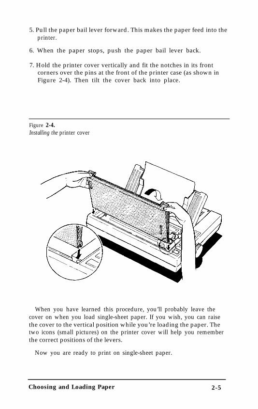
5. Pull the paper bail lever forward. This makes the paper feed into theprinter.
6. When the paper stops, push the paper bail lever back.
7. Hold the printer cover vertically and fit the notches in its frontcorners over the pins at the front of the printer case (as shown inFigure 2-4). Then tilt the cover back into place.
Figure 2-4.Installing the printer cover
When you have learned this procedure, you’ll probably leave thecover on when you load single-sheet paper. If you wish, you can raisethe cover to the vertical position while you’re loading the paper. Thetwo icons (small pictures) on the printer cover will help you rememberthe correct positions of the levers.
Now you are ready to print on single-sheet paper.
Choosing and Loading Paper 2-5

If the paper does not loadIf the platen (the black roller) turns but the paper does not load,
remove the paper from the printer and try again, starting at Step 2.This time press the paper a little more firmly into place.
If nothing happens at all, see that the printer is ON and that theON LINE light is off. Then remove the paper and try again.
Reloading during printingWhen you print a document more than one page long using single
sheets of paper, there are two different ways your software can allowyou to load a new sheet at the end of a page.
l If your software sends characters in a continuous stream, the printerstops printing when it reaches the bottom of the paper and soundsthe beeper. When this happens, the ON LINE light goes offautomatically.
l If your software handles printing page by page, it probably stopssending characters at the end of a page and prompts you to insertmore paper. In this case the ON LINE light probably remains on, andthe first thing you should do is press the ON LINE button once toturn it off.
Once the ON LINE light is off, remove the sheet that has just beenprinted and load a new sheet in the same way as before.
Reinstalling the Tractor Unit
When you want to switch from single-sheet to continuous-feed paper,you need to reinstall the tractor unit.
1. Remove the printer cover.
2. Hold the tractor with the gears to the right and fit the rear notcheson the tractor unit over the rear mounting pins on the printer, asshown in Figure 2-5.
3. Tilt the tractor unit toward you until the front latches click in placeover the front mounting pins on the printer.
2-6 Choosing and Loading Paper

Figure 2-5.Reinstalling the tractor unit
Choosing and Loading Paper 2 - 7

The Paper Thickness Lever
You can adjust the FX to accommodate different thicknesses of paper.You need to do this when you print carbon copies.
Before moving the paper thickness lever, always turn off the power,open the printer cover or the tractor cover, and move the print head tothe middle of the printer.
The paper thickness lever (shown in Figure 2-6) has six positions.
Figure 2-6.Paper thickness lever
2-8 Choosing and Loading Paper

If you want to change or check the lever, push it toward the platen(the black roller) until it stops. This is the first position. Then pull thelever toward you. You will feel three more click stops. The table belowshows which position you should use.
Table 2-I. Paper thickness lever positions
Paper Leverthickness position
Single 2ndWith 1 copy 3rdWith 2 copies 4th
*Maximum total thickness IS 0.25mm
Position 1 is for thinner paper, and positions 5 and 6 are forthicker paper. These positions should rarely be used. If they are,the printing quality will not necessarily be as good as on paper asspecified in the technical specifications.
Always return the lever to the second position when you resumeprinting on normal paper.
Choosing and Loading Paper 2 - 9

Chapter 3
Using the FX with Application Programs
Now that you’ve set up and tested the printer, you need to startusing it with your application programs.
Printer Selection Menus
Most application programs let you specify the type of printer you’reusing so that the program can take full advantage of the printer’sfeatures. Many programs provide an installation or setup procedurethat presents a list of printers to choose from. If your applicationprogram has a printer selection menu, use the instructions below.
The rest of this chapter covers word processors, spreadsheets,graphics programs, and programming languages.
Menu selectionsIf your software has a printer selection menu, simply choose FX-86e
or FX-286e. If the menu does not list either of these printers, chooseone of the following. They are listed in order of preference.
FX-86eEX-800FX-85FX-80 +FX-80FXLXEpson printerDraft printer
F X - 2 8 6 eEX-1000FX-286FX-185FX-100+FX-100FXLXEpson printerDraft printer
If you plan to use the IBM printer emulation mode, choose IBMProprinter (if you have an FX-86e), IBM Proprinter XL (if you have anFX-286e), IBM Graphics printer, or IBM printer, in that order ofpreference.
Using the FX with Application Programs 3-1

NoteIf your application program does not list the FX-86e or FX-286e, youmay want to contact the manufacturer to find whether an update isavailable.
A quick testAfter setting up your application program, print a sample document
to be sure the program and the FX are communicating properly. If thedocument doesn’t print correctly, recheck the program’s printerselection and installation procedure. If you’re still having troubleprinting, consult the troubleshooting section in Appendix C.
Computer - Printer Communication
Computers and printers communicate by using codes to representcharacters and commands. To be sure the two devices use the samecodes, almost all manufacturers of computers, printers, and softwareuse the American Standard Code for Information Interchange, whichis usually referred to by its abbreviation, ASCII.
The ASCII standard includes codes for printable characters (letters,punctuation marks, numerals, and mathematical symbols) and 33 othercodes called control codes. The control codes are for such functions assounding the beeper and performing carriage returns. Because the 33control codes are not enough to control all possible printer functions,most printer commands are actually a sequence of two or more codes.
One of the 33 control codes, the escape code, signals the beginningof a sequence of codes. Therefore, most printer commands aresequences of codes, the first of which is the escape code. This manualuses the ASCII abbreviation ESC for this code.
When using control codes to select printer functions for anapplication program or programming language, check the manual forthe program or language to find the appropriate method of insertingthe code into the program. Further details on the methods to use are inthe rest of this chapter.
Naming and using commandsThe most common way of naming codes or commands is with one of
two numbering systems, decimal or hexadecimal.
3 - 2 Using the FX with Application Programs

The decimal system is the standard numbering system based on unitsof ten, using the numerals O-9.
The hexadecimal, or hex, system is based on units of 16 and is oftenused by programmers. Instead of using only the numerals 0 through 9,the hex system also uses the letters A through F. For example, thedecimal numbers 9, 10, 11, and 12 are 09, 0A, 0B, and 0C in hex.
Since the most frequently used hexadecimal numbers are between 0and FF hex (0 to 255 in decimal), it’s common to write hexadecimalnumbers that are less than 16 with a zero in front, as shown above.
In this book, hex numbers are distinguished from decimal numbersby the word hex after them (for example, 1B hex). Other commonways of denoting a hexadecimal number are the following:
1BH $1B &1B &HlB <1B>H
The Command Summary and the Quick Reference card give boththe decimal and hex numbers for each command.
Word Processors
In many ways, word processors demand the most from your printer.When you create and print a document, you may use many print stylesand fonts, add headers and footers, and use bold, italic, and othereffects.
Once you have installed your word processor by using the lists onpage 3-1, you can ordinarily use a fixed set of printer features by usinga word processor command to place markers around the text to bealtered. When the document is printed, the markers are recognized andtranslated into suitable commands for your printer. On your screensome programs show the markers; others display the text as it willappear-for example, in bold or italics.
This method is normally restricted to features that can be found onalmost all printers, such as bold and underlining.
Some programs also provide a way of placing complete printercommands in the text. These commands may or may not be visible onyour screen. This method has the advantage of allowing you to use anyprinter command, not just a limited set. To make use of it, however,you need to understand how to use the printer’s commands.
Using the FX with Application Programs 3-3

Check the manual for your word processor to see if you can placeprinter commands in your text. If this is possible, use the CommandSummary (Appendix A) in this manual to find the command, and usethe manual for your word processor to find how to assign thecommand.
If your FX is not printing correctly, check both the FX and yourword processor and do the following:
l Make sure you’ve selected the correct printer.
l Carefully read the printer setup and installation information in yourword processor’s manual.
l Check the printer options that may be part of the installation orsetup section (line feeds, interface, etc.).
l Make sure your word processor is capable of sending the propercommands to your printer.
If you’re still having difficulty printing, check the troubleshootingsection in your word processor’s manual and Appendix C of thismanual.
Spreadsheets
Although spreadsheets seldom use as many printing styles as wordprocessors, they do have some very specific requirements.
Installation and column widthIf your spreadsheet program provides a list of printers, use the list on
page 3-1 to find the proper selection. If your spreadsheet doesn’t have aprinter setup routine, carefully read the program’s manual forinformation on printing.
A major concern for printing spreadsheets is the width of the printer.The FX-86e is an 80-column printer, and the FX-286e is a 136-columnprinter. You can, however, increase the number of characters on a lineby using one of the modes in Table 3-1. You can turn on condensedwith a button on the control panel (see SelecType in Chapter 1), andthe other modes are explained in Chapter 4.
3-4 Using the FX with Application Programs

Table 3-1. Characters per lineFX-86e FX-286e
Normal 80 136Elite 96 163Condensed 132 233Condensed Elite 160 272
Therefore, if your spreadsheet asks the number of columns your printercan print, decide which mode you will use and supply the appropriatenumber from Table 3-1.
Printer commandsUnlike word processors, spreadsheet programs usually don’t let you
change printer commands within a spreadsheet. Instead, one style ormode of printing is used for the whole spreadsheet. With the FX, thereare two main ways of sending commands to control the printing of aspreadsheet.
First, almost all spreadsheets have the capability of sendingcommands to a printer. Look in the manual for your spreadsheet tofind out how to send printer commands. Then look in the CommandSummary (Appendix A) in this manual to find the proper codes tosend.
For example, your spreadsheet might use a “setup string” to sendprinter commands. To prepare a setup string for condensed elite, youwould look up the proper command in the Command Summary.
The command for elite is ESC M, and the command for condensedis SI. Because most spreadsheets use the decimal equivalent for thecommands, (also given in the Command Summary), a setup string forcondensed elite might look like this:
/027/077/015
The number 027 is for the escape code, 077 is for M, and 015 is for SI(condensed).
The second method to choose condensed is one of the SelecType con-trol panel buttons. The use of this button is described in Chapter 1.
If your spreadsheet is not printing correctly, be sure you have selectedthe correct printer if the program asks you to select one.
Using the FX with Application Programs 3-5

If you’re using the program’s print facility, recheck the FX’sCommand Summary to make sure you’re sending the correctcommands.
If you’re still having difficulty printing, check the troubleshootingsection in your spreadsheet program’s manual or Appendix C of thismanual.
Graphics Programs
The FX is capable of producing finely detailed graphic images.Although Chapter 5 gives specific information on the graphicscommands, the easiest way to take advantage of the FX’s capabilities iswith one of the many graphics programs available.
When buying graphics software, always make sure it has a suitableoption to allow printouts on an FX printer. Any program with anoption for an FX printer should give excellent results, using differentdot densities to produce a realistic scale of grays.
Most graphics programs have a printer selection procedure, in whichcase you should check the lists on page 3-1 to find the proper selection.
Programming Languages
Most users rely on application programs to send commands to theprinter. An awareness of programming languages, however, can behelpful in exploring a printer’s potential or troubleshooting a printingproblem.
For example, if you want to set up your application program to senda command for italic printing, you can use a programming language,such as BASIC or Pascal, to do a quick printout before setting up theprogram.
If, on the other hand, you’ve set up a program to send a certaincommand to the printer, but it’s not printing correctly, you can sendthe same command with a programming language to find whether theproblem lies with your application program, the command, or theprinter.
3-6 Using the FX with Application Programs

Sending printer commands with BASICYou can send printer commands with any programming language.
The examples in this manual are written in BASIC, because BASIC isincluded with most computer systems.
In most forms of BASIC, and in particular Microsoft’” BASIC, thenormal method of producing printed output is to use the LPRINTstatement followed by the text to be printed enclosed in quotationmarks, as shown below:
100 LPRINT "This text will be printed."
Individual printer control codes can be sent by using the CHR$function with the LPRINT statement:
110 LPRINT CHR$(27);CHR$(69);
This line sends ASCII codes 27 and 69 to the printer, selectingemphasized printing.
Most versions of BASIC permit the ASCII codes in the CHR$function to be given in either decimal (as above) or hexadecimal. Also,if the code corresponds to a printable character, the character itself canbe used in quotation marks in the LPRINT statement. The commandshown above could therefore be given in two other forms:
LPRINT CHR$(27);"E"LPRINT CHR$(&H1B);CHR$(&H45)
As you can see, Microsoft BASIC uses &H to denote hexadecimalnumbers.
If you have another version of BASIC or a different programminglanguage, consult the manual for the language to find the correctformats for these commands.
Using the FX with Application Programs 3 - 7

Chapter 4
FX Printer Features
You can obtain many different printing effects with the FX printer,from arranging the printout on the paper to giving extra emphasis toparticular words and phrases. This chapter shows you the features youmay want to select with your software. Once you have read about thefeatures, you can find their commands in the Command Summary.
SelecType, as you know, controls the printing style of a wholedocument. Software commands, on the other hand, can changeanything from a single character to the entire document.
Quality and Fonts
The most fundamental changes you can make to printing on the FXare in the print quality and NLQ fonts.
The FX has two levels of print quality: draft and NLQ (Near LetterQuality). Draft printing is fast, making it ideal for drafts and otherpreliminary work. NLQ printing takes a little longer, but it producesmore fully-formed characters for presentation-quality documents.
The printout below shows the differences between draft, NLQRoman, and NLQ Sans Serif so that you can compare the differentstyles and densities:
D r a f t p r i n t i n g i s e x t r e m e l y f a s t .
NLQ Roman is clear and typewriter-like.NLQ Sans Serif is crisp and distinctive.
SelecType gives you an easy way of changing the print quality andNLQ font, but if you prefer to print in NLQ Roman most of the time,you can select it with a DIP switch (see Appendix D). You can alsochoose the print quality and NLQ font with software commands.
FX Printer Features 4-1

Print Size and Character Width
To add greater variety to your documents, the FX has two pitches aswell as proportional spacing and condensed, double-wide anddouble-high printing. All can be selected with a software command,and condensed can be selected with SelecType.
Pitches and Proportional Spacing
The two pitches are pica and elite. Pica is 10 characters per inch (cpi)and elite is 12 cpi. The printout below shows the difference between thetwo .
Pica: ABCDEFGHIJKLMnopqrstuvwxyzElite: ABCDEFGHIJKLMnopqrstuvwxyz
Another mode is proportional. In this mode the width of thecharacters varies. Therefore, a narrow letter like i receives less spacethan a wide letter like W, as you can see in the printout below:
Pica: ABCDEFGHIJKLMnopqrstuvwxyzProportional: ABCDEFGHIJKLMnopqrstuvwxyz
The character tables in Appendix B list the widths of all proportionalcharacters.
Double-wide, double-high, and condensedIn addition to the basic pitches and the proportional mode, the FX
offers three other modes that change the size of your printing. Thesemodes are double-wide, double-high, and condensed.
The double-wide mode doubles the width of any size of characters.This mode is useful for such purposes as emphasizing headings inreports and making displays, but is usually not suitable for largeamounts of text.
D o u b l e - w i d e p i c aD o u b l e - w i d e e l i t e
4-2 FX Printer Features

Another mode for headings and other special uses is double-high,which is shown below.
This is double high printing
Because of its height you must leave a blank line above a line ofdouble-high. Otherwise the double-high letters will overlap the letterson the previous line.
Pica and elite can be reduced to about 60% of their normal widthwith the condensed mode. This mode is particularly useful for printingwide spreadsheets because condensed elite allows you up to 160characters on an B-inch line and 272 on a 13½-inch line.
Condensed can be selected with SelecType, by setting a DIP switch(see Appendix D), or with a software command. Even if you turncondensed on with the DIP switch, you can still turn it off withSelecType or the software command.
Condensed pica gives more characters on a line.Condensed elite gives you even more.
Widening or narrowing the characters also widens or narrows thespaces between words and letters. Because word processors usuallycreate a left margin by printing spaces, you may need to change thenumber of characters on a line to keep the margins correct if youchange widths. For example, a left margin of five pica characters is thesame as one of six elite characters.
Special Effects and Emphasis
The FX offers two ways of emphasizing parts of your text and alsoallows you to use underlining, superscripts, and subscripts. Thesefeatures can be controlled only by software commands, but manyapplication programs can produce them if they are properly installed.
Emphasized and double-strike modes both slow the printer downslightly to produce bolder text. In emphasized mode, the FX printseach character twice as the print head moves across the paper, with thesecond slightly to the right of the first. This produces darker, morefully-formed characters.
FX Printer Features 4-3

In double-strike mode, the FX prints each line twice, with the secondslightly below the first. This makes the characters bolder. While NLQ isin use, however, double-strike is ignored because NLQ characters arealready formed by two passes of the print head.
This is normal NLQ printingThis is emphasized NLQ printing
Superscripts and subscripts are valuable for such purposes as printingfootnote numbers or parts of mathematical formulas, and the underlinemode provides an automatic way of underlining fully any piece of text.It underlines spaces, subscripts, and superscripts without a break.
The example below shows underlining with text and combined withsuperscripts and subscripts in a mathematical formula.
average = (a1 + a2 + . . . . . + an)n
Using Different Character Sets
The FX incorporates a new character set: Epson Character Graphics.This set allows you to take advantage of the power of the Epson modecommands and still print out the character graphics used by IBM andcompatible computers and by much commercial software. For example,if your word processor can include the characters to draw boxes andshade areas, you can produce some very professional effects.
You can select the Epson character graphics set with your software orby setting DIP switch 1-3 ON. For many applications it is best to usethe DIP switch instead of the software command because the charactergraphics are then available as soon as you turn the printer on.
4-4 FX Printer Features

The other important change you can make to the standard characterset is to change some characters for ones commonly used in otherlanguages-chiefly European and Scandinavian-such as accentedcharacters and symbols. In Epson mode, eight international charactersets can be selected by setting DIP switches 1-6 to 1-8: USA, French,German, UK, Danish, Swedish, Italian, and Spanish. See Appendix Dfor the DIP switch settings.
In Epson mode, these eight, and five more, can also be selected by asoftware command. The additional character sets are the following:Norwegian, a second Danish set, Japanese, a second Spanish set, andLatin American. A complete list of these characters is in Appendix B.
Also, all text characters can be printed in italics in Epson mode. Youcan use this typestyle for special emphasis or as an alternative typeface.
Italics give emphasis to words.They are an attractive alternative style.
Page Layout and Other Commands
The remaining commands in the command summary are notnormally needed when using commercial software. You may need someof them if you are using a printer installation program provided withan application package, but most deal with features (such as tabs,margins, and line spacing) that are provided directly by commercialprograms and are therefore only useful to you if you want to programthe printer using a programming language such as BASIC.
FX Printer Features 4-5

Chapter 5
Graphics and User-defined Characters
The dot graphics mode allows your FX to produce pictures, graphs,charts, or almost any other pictorial material you can devise, and theuser-defined character feature allows you or a commercial softwareprogram to put special characters in the FX’s memory so that it canprint them just as if they were ordinary letters.
Because many commercial software programs use graphics, you maybe able to print pictures and graphs like the ones on this page and thenext by simply giving your software a few instructions.
The quickest and easiest way to print graphics on your FX is to use acommercial graphics program. With such programs you usually createan image on your monitor and then give a command to send theimage to the printer.
Graphics and User-defined Characters 5-1

If you use commercial software that produces graphics, all you needto know about dot graphics is how to use the software. If, on the otherhand, you wish to do your own programming or merely wish tounderstand how the FX prints graphics, read on.
The Print Head
To understand dot graphics you need to know a little about how theFX’s print head works.
The FX’s print head has nine pins. As it moves across the page,electrical impulses cause the pins to fire. Each time a pin fires, it strikesthe inked ribbon and presses it against the paper to produce a smalldot. As the head moves across the paper, the pins fire time after time indifferent patterns to produce letters, numbers, or symbols.
5 - 2 Graphics and User-defined Characters

Dot patterns
The FX’s print head is able to print graphics in addition to textbecause graphic images are formed on the FX about the same way thatpictures in newspapers and magazines are printed.
If you look closely at a newspaper photograph, you can see that it ismade up of many small dots. The FX also forms its images withpatterns of dots, as many as 240 dot positions per inch horizontally and72 dots vertically. The images printed by the FX can, therefore, be asfinely detailed as the one on the first page of this chapter.
In its main graphics mode the FX prints one column of dots for eachcode it receives, and it uses only the top eight of the nine pins.Therefore, your graphics program must send codes for dot patterns,one number for each column in a line. For each of those columns theprint head prints the pattern of dots you have specified.
To print figures taller than eight dots, the print head makes morethan one pass. The printer prints one line, then advances the paperand prints another, just as it does with text.
To keep the print head from leaving gaps between the graphics linesas it does between the text lines, the line spacing must be changed toeliminate the space between lines. With a change in line spacing, theFX can print finely detailed graphic images that give no indication thatthey are made up of separate lines, each no more than 8/72nds of aninch tall.
Each pass of the print head prints one piece of the total pattern,which can be as tall or short and as wide or narrow as you desire. Youdon’t have to fill the whole page or even an entire line with yourgraphics figures. In fact, you can use as little or as much space as youlike for a figure and put it anywhere on the page.
Pin Labels
The graphics mode requires a method to tell the printer which pinsto fire in each column. Since there are 256 possible combinations ofeight pins, you need a numbering system that allows you to use a singlenumber to specify which of the 256 possible patterns you want. Thisnumbering system is shown in Figure 5-1 on the next page.
Graphics and User-defined Characters 5 - 3

To fire any one pin, you send its number. To fire more than one pinat the same time, add up the numbers of the pins and send the sum tothe printer. Therefore, with these labels for the pins, you fire the toppin by sending 128. To fire the bottom pin, you send 1. If you want tofire only the top and bottom pins, you simply add 128 and 1, thensend 129.
By adding the appropriate label numbers together, you can fire anycombination of pins. Figure 5-1 shows three examples of how tocalculate the number that fires a particular pattern of pins.
Figure 5-1.Pin numbering system
128 128 128 128 12864 64 6 4 64 32 32 32 32 16 16 16 8 8 8 8 84 4 4 4 2 2 2 2 2 21 1 1
170 74 134
With this numbering system, any combination of the eight pins addsup to a decimal number between 0 and 255, and no numbers areduplicated. Before you can put these numbers in a graphics program,however, you need to know the format of the graphics commands.
Graphics Commands
The graphics mode commands are quite different from most othercommands. For most of the other modes, such as emphasized anddouble-wide, one command turns the mode on and another turns itoff. For graphics, the command is more complicated because thecommand that turns on a graphics mode also specifies how manycolumns of graphics will be printed. After the printer receives thiscommand, it interprets the next numbers as pin patterns and printsthem on the paper.
5 - 4 Graphics and User-defined Characters

The graphics command formatThere are several different graphics commands giving different
horizontal dot densities and printing speeds. Because the format isalmost the same for all the commands, however, the example herekeeps things simple by using only the single-density graphics command,ESC K. In single-density graphics, there are 60 dots per inchhorizontally.
The command to enter single-density graphics mode is ESC K nl n2.In BASIC the command is given in this format:
LPRINT CHR$(27);"K";CHR$(nl);CHR$(n2);
ESC K specifies single-density graphics, and the next two numbers(nl and n2) specify the number of columns reserved for graphics.
Column reservation numbersEven in single-density graphics mode, one 8-inch line can
accommodate 480 columns of graphics; in quadruple-density, almost2000 columns can fit on the same 8-inch line. Since the printer doesnot use decimal numbers larger than 255, the graphics commands usetwo numbers for reserving columns.
Because the commands are set up for two numbers, you must supplytwo even if you need only one. When you need fewer than 256columns, it is easy to determine nl and n2: nl is the number ofcolumns you are reserving and n2 is zero. For example, to send data for200 columns of graphics, nl is 200 and n2 is 0.
For more than 256 columns of graphics data, n2 is the number ofcomplete groups of 256 columns, and n1 is the number of columns tocomplete the line. For example, to send 1632 columns of graphic data,nl is 96 and n2 is 6 because 96 + (6 x 256) = 1632.
You can calculate both nl and n2 by dividing the total number ofcolumns by 256. The quotient is n2 and the remainder is nl. If you areusing a programming language with MOD (modulus) and INT (integer)functions, you can use the following formulas, in which n is the totalnumber of columns.
n1 = n MOD 256n2 = INT (n/256)
Graphics and User-defined Characters 5 - 5

Graphics data
After receiving a graphics command such as ESC K nl n2, theprinter prints the number of codes specified by nl and n2 as graphicsdata, no matter what codes they are. This means that you must be sureto supply exactly the right amount of graphics data. If you supply toolittle, the printer will stop and wait for more data and will seem to belocked. The next data sent will then be printed as graphics, even if it isreally text. On the other hand, if you supply too much graphics data,the excess will be printed as regular text.
Simple Graphics Programming
The first example in this section shows how a graphics command,column reservation numbers, and data can be used to print a singleline of graphics. The example is a BASIC program. If you preferanother programming language, the principles are exactly the same.Therefore, you can easily adapt the program to the language you prefer.
The first line of the program specifies single-density graphics for 40columns:
100 LPRINT CHR$(27);"K";CHR$(40);CHR$(0);
The second line is the data that is printed as pin patterns. It uses thenumber 74 to produce one of the patterns shown in Figure 5-1. TheFOR-NEXT loop sends 40 columns of data.
200 FOR X=1 TO 40: LPRINT CHR$(74);: NEXT X
That is the whole program. In BASIC, semicolons at the ends of thelines are very important; they prevent the computer from sendingother codes after the ones you specify. In other languages you may haveto use a special command to send a single code at a time. Run theprogram to see the result below. Although it is not as interesting as theexamples at the beginning of this chapter, it shows exactly how themode works.
5 - 6 Graphics and User-defined Characters

WIDTH statements
Some software (including most versions of BASIC) automaticallyinserts carriage return and line feed codes after every 80 or 130characters. This is usually no problem with text, but it can spoil yourgraphics. Two extra columns of graphics are printed in the middle ofthe ones you send, and are left over and printed as text.
In some versions of BASIC you can prevent unwanted controlcodes in graphics by putting a WIDTH statement at the beginning ofall graphics programs. The format in many forms of BASIC is eitherWIDTH “LPTl:“, 255 or WIDTH LPRINT 255. Check your softwaremanual for the proper format.
Printing taller patterns
The next example shows how several lines of graphics can be formedinto a figure taller than eight dots. It uses programming techniques forproducing textured or repetitive patterns.
The program is listed below. The lines inside each pair of FOR andNEXT statements have been indented so that you can see how theprogram works; the spaces are not needed for the program to run.
100 WIDTH "LPTl:", 255110 LPRINT CHR$(27);"A";CHR$(8);120 FOR R = 1 TO 6130 LPRINT CHR$(27);"K";CHR$(100);CHR$(0);140 FOR X = 1 to 50150 LPRINT CHR$(170);CHR$(85);160 NEXT X: LPRINT170 NEXT R180 LPRINT CHR$(27);"@"
If you run the program, you will see how it combines six print linesinto a pattern.
There are five basic steps that the program goes through to producethis kind of pattern.
Graphics and User-defined Characters 5-7

1. The computer is prevented from adding any extra characters by theWIDTH statement (line 100).
2. The line spacing is changed to 8/72 of an inch-the height of thedot patterns used in the program (line 110).
3. The program goes through the graphics commands the requirednumber of times (lines 120 and 170).
4. A new graphics command is used for each line printed (lines 130-160). This part of the program is similar to the last example, but twocolumns are printed each time through the loop making a total of100.
5. The last important thing to do is to reset the printer to its defaultsettings, including the normal line spacing (line 180).
Notice that the graphics command (ESC K) can be in effect for onlyone print line. To print more than one line of graphics, the graphicscommand must be issued before each line.
Density Varieties
Although all the examples so far in this chapter have been in thesingle-density graphics mode, there are six other eight-pin densities andtwo that use all nine pins. Nine-pin graphics is not necessary for mostuses, but you can find the command (ESC ^) in the Epson modecommand summary.
The four most common eight-pin modes are available in both Epsonand IBM printer emulation modes. Their commands are ESC K,ESC L, ESC Y, ESC Z. In Epson mode, there is also a general-purposecommand for any of the eight-pin graphics modes: ESC *. Thiscommand is used in the same way as the individual commands, exceptthat before n1 and n2 you must send the code for the graphics moderequired. The different modes are summarized in the table on the nextpage.
The following example shows how to use the ESC * command toreserve 40 columns for single-density graphics. This uses mode number0 from the table to achieve exactly the same effect as the first exampleusing ESC K.
LPRINT CHR$(27);"*";CHR$(0);CHR$(40);CHR$(0);
5 - 8 Graphics and User-defined Characters

Table 5-1. Graphics modes
Alternate Horiz. densityOption Code m (dots/in.)Single-density ESC K 0 60 Double-density ESC L 1 120 High-speed double-density* ESC Y 2 120 Quadruple-density* ESC Z 3 240 CRT I none 4 80 Plotter (1:1) none 5 72 CRT II none 6 90 Double-density plotter none 7 144
*Adjacent dots cannot be printed in this mode.
Modes 4-7 in the table are special modes that alter the horizontaldensity to give proportions of a computer monitor (the CRT modes),or to match the vertical density so as to give round circles (the plottermodes).
In two modes, high-speed double-density and quadruple-density, theprint head cannot print two consecutive dots with the same pin, sothat it can print dots in only half the possible dot positions in any onerow. The higher density means that the resolution of the pattern isbetter than in single-density mode. When you design patterns in thesetwo modes, however, you must see that no dots overlap.
Reassigning a graphics modeAnother graphics command lets you assign a different eight-pin
graphics mode to one of the specific eight-pin graphics commands. Youcan use it with graphics software programs to quickly change thedensity and proportions of your printouts. Changing the graphicsoption changes the width without changing the height.
The command for reassigning a graphics mode is ESC ? c m. In thiscommand, c is a letter designating one of the four alternate graphicscodes (K, L, Y, or Z) and m is the mode number of the new mode, aslisted in Table 5-1.
For example, to change the ESC K command to select the CRT Iscreen graphics mode, the command in BASIC would be the following:
LPRINT CHR$(27);"?K";CHR$(4);
Graphics and User-defined Characters 5 - 9

A little experimentation should tell you whether the reassigning codecan improve your graphics printouts.
Designing Your Own Graphics
This section takes you through the development of a graphicsprogram. The example is not especially complicated, but it does includethe same steps you would use for a more complex figure.
You should plan your figure with dots on graph paper, but beforebeginning to place the dots, you must decide which graphics densityyou want. Figure 5-2 shows the differences between three commonmodes so that you can choose the one you want.
In this figure you can see the main rules for graphic design in thethree densities:
l In single-density no dots can be placed on vertical lines.
l In high-speed double-density, dots can be placed on vertical lines, butno dots can overlap.
l In low-speed double-density, dots can be placed on vertical lines, andthey can overlap.
Figure 5-2.Designing in different densities
Single High-speeddouble
Low-speeddouble
5-10 Graphics and User-defined Characters

Now look at the high-speed double-density design in Figure 5-3. Itshould point you in the right direction for your own work.
Figure 5-3.Arrow design
After plotting the dots on a grid, you calculate the numbers for eachpin pattern by dividing the design grid into separate print lines. For thearrow design, the grid was divided into two lines, each seven dots high.Then each column was examined to calculate the graphics data. Theresults for the first line are shown in Figure 5-4. The pin values are onthe left and the sums at the bottom of each column.
Figure 5-4.Calculating data
Graphics and User-defined Characters 5 - 1 1

The numbers for the second line were calculated in the same way.Once the numbers for the pin patterns are calculated, they are put inthe program in DATA statements, separated by commas.
The program works in a similar way to the last example. This time itselects 7/72-inch line spacing because only seven pins are used. Becausethe data is not repetitive, each column of graphics data is read from theDATA statements and sent to the printer. The design is 41 dotpositions wide. Therefore both lines 130 and 140 use the number 41.
100 WIDTH "LPTl:", 255110 LPRINT CHR$(27);"A";CHR$(7); 120 FOR ROW = 1 TO 2130 LPRINT CHR$(27);"Y";CHR$(41);CHR$(0); 140 FOR COLUMN = 1 TO 41150 READ N160 LPRINT CHR$(N);170 NEXT COLUMN180 LPRINT190 NEXT ROW200 END210 DATA 64,32,80,8,68,2,64,0,64,0 220 DATA 64,0,64,0,32,0,16,0,8,0230 DATA 8,0,8,0,8,0,8,0,8,0,8,0,8,0240 DATA 184,64,32,16,8,4,2 250 DATA 8,16,40,64,136,0,8,0,8,0 260 DATA 8,0,8,0,16,0,32,0,64,0,64,0 270 DATA 64,0,64,0,64,0,64,0,64,0,64,0 280 DATA 116,8,16,32,64,128,0
When you run this program, it produces the following printout:
If you want to see the figure in other densities, change the Y in line130 to L or Z.
5 - 1 2 Graphics and User-defined Characters

User-defined Characters
The FX has a command that allows you to define and printcharacters of your own design. You can design an entirely newalphabet or typeface, create mathematical or scientific symbols, orcreate graphic patterns to serve as building blocks for larger designs.These user-defined characters work only in draft mode.
Also, you can buy commercial software programs that assist you increating characters or supply you with sets of characters alreadycreated. In addition, some popular application packages make use ofthe user-defined character function to enhance printouts. (Thesecharacters are called download characters in some programs.)
The printout below shows a few user-defined characters to give youan idea of what can be done, but remember that you can create whatyou need or want.
When you define a character of your own, the definition is stored intemporary memory (RAM). The original character with the same coderemains in the printer’s permanent memory (ROM) and you can printeither of them when needed.
Design gridsThe process of defining a character is much like printing dot graphics
because you send the printer precise instructions on where you wanteach dot printed. In fact, planning a user-defined character is likeplanning a small dot graphics pattern.
To design a character you use a grid that has nine rows and elevencolumns. Figure 5-5 on the next page shows three of these grids. Mostcharacters do not use the two rows below the heavy line. Those rowsare only for characters with descenders, like y and g. Also, eventhough you can use up to 11 columns, it is best to leave the last twoblank for the space between characters.
The grid in the middle of Figure 5-5 shows a plan for a character.Although there are nine pins in the FX print head, you can use onlyeight of them in a single user-defined character. The design in
Graphics and User-defined Characters 5-13

Figure 5-5 uses the top eight, but you can also use the bottom eight byusing the grid on the right as explained later in this section.
Once the character is planned on the grid, you simply add the pinvalues for each column together, just as you do for graphics. Then, thenext step in defining a character is to send this information to theprinter.
Figure 5-5.Design grids
1286432168421
1 2 3 4 5 6 7 8 9 1 2 3 4 5 6 7 8 9 1 2 3 4 5 6 7 8 9
12864
3216
8421
128
643216
8421
Sending the character definition
The command to define characters is complex:
ESC & 0 nl n2 al dl . . . d n
You can define more than one character with a single command.The values nl and n2 are the ASCII codes of the first and lastcharacters you are defining. If you are defining only one character, nland n2 are the same. You can use any codes between 32 and 127 or 161and 254 decimal for nl and n2, but it is best not to define decimal 32,which is the code for a space. You can also use other codes by using theESC 6 and ESC I commands (see the Command Summary).
An example will show how to specify nl and n2. If, for instance, youwant to redefine the characters A to Z, nl is A (or ASCII code 65) andn2 is Z (or ASCII code 90). So the command ESC & 0 AZ (followedby the appropriate data) would replace the entire alphabet of capitalletters.
5-14 Graphics and User-defined Characters

Following the specification of the range of characters to be defined inthis command is one number (al) that specifies the width of thecharacter and whether it uses the top eight pins or the bottom eightpins.
The last part of the character definition is the actual data thatdefines the dot patterns for each column of each character. Since acharacter can use up to eleven columns, you must supply eleven datanumbers for each character even if some of the columns are blank.
An example character definition program should make the processclear:
100 LPRINT CHR$(27);"x0"; 110 LPRINT CHR$(27);"&";CHR$(0); 120 LPRINT "@@";130 LPRINT CHR$(l36);140 FOR I = 1 to 11150 READ A: LPRINT CHR$(A);160 NEXT I170 LPRINT "@ @ @ @ @"180 LPRINT CHR$(27);"%l";CHR$(1); 190 LPRINT "@ @ @ @ @"200 LPRINT CHR$(27);"%";CHR$(0); 210 LPRINT "@ @ @ @ @"220 END230 DATA 32,80,168,84,42,84,168,80,32,0,0
In line 100, the ESC x 0 command selects draft style printing. Theactual character definition starts in line 110. The two at signs (@) inline 120 are nl and n2, the range of characters being defined (in thiscase, a range of one). Line 130 contains a1.
The information about the character design (which is contained inthe data statements at the end of the program) is sent to the printer inthe loop between lines 140 and 160.
This example program defines a heart and places it in the area ofRAM reserved for ASCII code 64, which corresponds to the at sign inthe characters in the ROM. The next part of the program (lines170-210) prints out a three-line sample. The first and third lines containat signs; the second line contains the heart that was defined.
Graphics and User-defined Characters 5 - 1 5

Run the program to see the printout below:
As you can see, both sets of characters (the original ROM charactersthat the printer normally uses and the user-defined character set)remain in the printer available for your use. The command to switchbetween the two sets is used in lines 180 and 200 and has the followingformat:
ESC % n
If n is 0, the normal ROM character set is selected. (This is thedefault.) If n is 1, the user-defined character set is selected.
You can switch between character sets at any time, even in themiddle of a line. To try it, place semicolons at the end of lines 170 and190 in the program above.
Copying ROM to RAMAfter running the program above, if you select the user-defined
character set and try to print other characters, the only one that willprint is the heart. If you send the code for a character that is notdefined, it is printed as a space.
In many cases, you will want to redefine only a few of the characters,leaving the rest of the alphabet as it is. As you have seen, it is possibleto switch back and forth between the normal character set and theuser-defined character set. Normally, it is more convenient to copy allof the standard characters from ROM to the area of RAM that holdsthe user-defined character set. The format of the command to do this isas follows:
ESC : 0 0 0
If you use this command at the beginning of a program, then definethe special characters you want to change, you can then select the user-defined character set and use it as your normal character set. There isthen no need to switch back and forth between sets.
5-16 Graphics and User-defined Characters

NoteThis command will cancel any user-defined characters you havealready created. You must send this command to the printer before youdefine characters.
Specifying the width and height
The example program uses 136 for al (in line 130 of the definitionprogram), but you can use other values. The number a1 specifies twothings: the width of the character and its position on the grid. Thewidth is used when the character is printed in proportional mode.
If you want a character to use the bottom eight pins, use the thirdgrid in Figure 5-5.
A value of 136 is suitable for all characters that use the top eight pinsand start in column I and finish in column 9. For a character the samewidth, but printed with the bottom eight pins, al should be 8. For anyother character follow these rules to calculate al :
1. If you design a character narrower than nine columns, you canbalance the number of empty columns on either side with thefollowing method: Starting with a1 equal to 8, subtract 1 for everyblank column on the right and add 16 for every blank column onthe left.
2. If the character should be printed with the top eight pins, add 128.
For example, if a character uses the top eight pins and starts incolumn 3 and ends in column 7, the calculation is as follows:
l start with al = 8
l subtract 2 for two blank columns on the right, giving a1 = 6
l add 32 for two blank columns on the left, giving a1 = 38
l add 128 to print with the top eight pins, so that a1 = 166.
Mixing print styles
The user-defined characters can be used in combination with mostprint styles (except NLQ, of course). For example, emphasized anddouble-wide work well with user-defined characters.
Graphics and User-defined Characters 5 - 1 7

The sample below shows the heart character printed in two differentstyles.
Other considerationsKeep in mind that user-defined characters are stored in RAM, which
is not permanent. Whenever the printer power is turned off or yourcomputer sends an initialization (NT) signal, all of the user-definedcharacters are lost. For example, some computers send an INIT signaleach time BASIC is loaded or when certain application programs startup, and most computers do it if you have to reset them. If the programresets the printer with the ESC @ command, the ROM set is selected,but the user-defined characters are not lost.
The IBM printer emulation mode has a different method of definingcharacters. See page A-45 in the Command Summary if you areinterested.
5-18 Graphics and User-defined Characters

Appendix A
Command Summary
This appendix lists and describes all the commands, both Epson(ESC/P) mode and IBM printer emulation mode, available on the FX.
The first part of this appendix lists all commands in numerical orderand gives the page number where each is fully described. If you knowwhich command you are looking for, consult the numerical list to findthe page number where it is described.
The Quick Reference card at the end of the book also contains a listof the commands divided by topic, with page number references thatdirect you to full explanations of the commands. The numerical listand the Quick Reference card also show the differences between theEpson mode and the IBM printer emulation mode.
The second part of this appendix lists and describes Epson modecommands and IBM printer emulation mode commands separately; thecommands are divided into the following subjects:
Printer OperationData ControlVertical MotionHorizontal MotionOverall Printing StylePrint Size
Print EnhancementWord ProcessingCharacter SetsUser-defined CharactersGraphics
Each command has a format section and a comment section. Theformat section gives the ASCII, decimal, and hexadecimal values forthe command; the comment section describes the effect of thecommand and gives any additional information necessary for using it.
All three formats are equivalent, and it should be easy to pick theone most suited to your purpose.
NoteSome application programs can use control key sequences. See theControl Key chart on page A-3 for information on using these.
Command Summary A . 1

For the following commands that use only 0 or 1 for the variable,either the ASCII codes 1 and 0 or the characters 1 and 0 can be used:
ESC S, ESC U, ESC X, ESC p, ESC W, ESC S, ESC - , andESC %
For example, in BASIC you can turn on double-wide with either ofthese statements:
LPRINT CHR$(27);"W";CHR$(l)LPRINT CHR$(27);"W";"l"
The simplest type of command consists of a single character to besent to the printer. For instance, to print in condensed mode the codeformat is:
ASCII code: S IDec imal : 15 Hexadecimal: OF
This code can be sent from a program by sending the code 15 directly.
More complex commands consist of two or more character codes.For example, to print in proportional mode the code format is thefollowing:
ASCII code: ESC nDecimal: 27 112 nHexadecimal: 1B 70 n
In this case n can be either 1 or 0, to begin or end proportionalprinting. You can use either of the following commands to turn ONproportional print from BASIC:
LPRINT CHR$(27);CHR$(112);CHR$(l)LPRINT CHR$(27);"p";CHR$(l)
A - 2 Command Summary

Control key chart
Some application programs can use control key codes for decimalvalues O-27. The table below gives you the proper values. The ControlKey column indicates that you press the control key at the same timeyou press the key for the letter or symbol in that column. For example,you press the control key and A at the same time to send the value 1.
Some programs that use this system cannot use control-@, andmany programs use the control keys for other purposes.
Dec. Hex. Control Key
0123456789
101112131415161718192021222324252627
00 @01 A02 B03 C04 D05 E06 F07 G08 H09 I 0A J 0B K0C L0D M0E N0F O 10 P
Q1112 R13 S14 T15 U16 V17 W18 X19 Y1A Z1B [
Command Summary A - 3

Commands in Numerical Order
This section lists all the FX commands, with their decimal andhexadecimal values. The numbers in the columns on the right are thepage numbers in this appendix where a complete description of thecommand can be found. If the Epson and IBM printer emulation modepage numbers are the same, the command is the same in both modesand is described only in the Epson mode section.
BEL 7 07 BeeperBS 8 08 BackspaceHT 9 09 Tab horizontallyLF 10 0A Line feedV T 11 0B Tab verticallyFF 12 0C Form feedC R 13 0D Carriage returnSO 14 0E Select double-wide (1 line)SI 15 0F Select condensed mode DC1 17 11 Select printerDC2 18 12 Cancel condensed modeDC2 18 12 Cancel condensed/eliteDC3 19 13 Deselect printerDC4 20 14 Cancel double-wide (1 line)CAN 24 18 Cancel lineDEL 127 7F Delete character ESC SO 14 0E Select double-wide (1 line)ESC SI 15 0F Select condensed modeESC EM 25 19 Automatic sheet feeder on/offESC SP 32 20 Set intercharacter spaceESC ! 33 21 Master selectESC # 35 23 Cancel MSB controlESC $ 36 24 Set absolute print positionESC % 37 25 Select user-defined setESC & 38 26 Define user-defined charactersESC * 42 2A Select graphics modeESC - 45 2D Turn underlining on/off
A-11 A-11A-19 A-19A-20 A-20A-14 A-14A-17 A-17A-13 A-13A-12 A-12A-24 A-24A-23 A-23
A-7 A-7A-24
A-42A-8
A-25 A-25A-12 A-12A-12A-24 A-24A-24 A-24A-10A-29A-22A-11A-19A-31A-31A-34A-28 A-28
A - 4 Command Summary

ESC /ESC 0ESC 1ESC 2ESC 2ESC 3ESC 4ESC 4ESC 5ESC 5ESC 6ESC 6ESC 7ESC 7ESC 8ESC 9ESC :ESC :ESC <ESC =ESC =ESC >ESC ?ESC @ESC AESC AESC BESC CESC COESC DESC EESC FESC GESC HESC IESC I
47 2F Select vertical tab channel A-1848 30 Select l/8-inch line spacing A-15 A-1549 3 1 Select 7/72-inch line spacing A-15 A-1550 32 Select l/6-inch line spacing A-1550 32 Select programmable line spacing A-385 1 33 Select n/216-inch line spacing A-16 A-1652 34 Select italic mode A-3052 34 Set top of form A-3853 35 Cancel italic mode A-3053 35 Turn automatic line feed on/off A-3954 36 Printable code area expansion A-3254 36 Select international character set A-4355 37 Cancel ESC 6 A-3255 37 Select standard character set A-4356 38 Disable paper-out sensor A-9 A-957 39 Enable paper-out sensor A-9 A-958 3A Copy ROM into RAM A-3158 3A Select elite pitch A-4160 3C Select unidirectional mode (1-line) A-861 3D Set MSB to 0 A-1061 3D Define user-defined characters A-4562 3E Set MSB to 1 A-1163 3F Reassign graphics mode A-3564 40 Initialize printer A-765 41 Select n/72-inch line spacing A-1665 41 Set n/72-inch line spacing A-3766 42 Set vertical tabs A-17 A-1767 43 Set page length in lines A-13 A-1367 43 Set page length in inches A-13 A-1368 44 Set horizontal tabs A-21 A-4069 45 Select emphasized mode A-26 A-2670 46 Cancel emphasized mode A-26 A-2671 47 Select double-strike mode A-26 A-2672 48 Cancel double-strike mode A-27 A-2773 49 Printable code area expansion A-3273 49 Select font A-40
Command Summary A - 5

ESC J 74 4A Perform n/216-inch line feedESC K 75 4B Select single-density graphicsESC L 76 4C Select double-density graphicsESC M 77 4D Select elite pitchESC N 78 4E Set skip-over-perforationESC O 79 4F Cancel skip-over-perforationESC P 80 50 Select pica pitchESC I’ 80 50 Turn proportional on/off (286e)ESC Q 81 5 1 Set right marginESC Q3 8 1 5 1 Deselect printer (86e)ESC Q22 8 1 5 1 Deselect printer (286e)ESC R 82 52 International character setESC R 82 52 Restore default tab settingsESC SO 83 53 Select superscript modeESC S l 83 53 Select subscript modeESC T 84 54 Cancel superscript/subscriptESC U 85 55 Turn unidirectional mode on/offESC W 87 57 Turn double-wide on/offESC X 88 58 Set left and right marginsESC Y 89 59 High-speed dbl-density graphicsESC Z 90 5A Quadruple-density graphicsESC [@ 91 5B Turn double-high on/off (286e)ESC \ 92 5C Set relative positionESC \ 92 5C Print characters from symbol setESC A 94 5E Select 9-pin graphicsESC A 94 5E Print 1 character from symbol setESC _ 95 5F Turn overscore on/offESC a 97 61 NLQ justificationESC b 98 62 Set vertical tabs in channelsESC k 107 6B Select NLQ fontESC l 108 6C Set left marginESC p 112 70 Turn proportional mode on/offESC s 115 73 Turn half-speed mode on/offESC t 116 74 Select character tableESC w 119 77 Turn double-high on/offESC x 120 78 Select NLQ or draft
A-16 A-38A-33 A-33A-33 A-33A-23A-14 A-14A-14 A-14A-22
A-41A-18
A-37A-37
A-30A-40
A-27 A-27A-27 A-27A-27 A-27
A-9 A-9A-25 A-25
A-39A-33 A-33A-34 A-34
A-42A-20
A-44A-35
A-44A-43
A-28A-17A-21A-18A-23
A-8A-29A-25A-21
A.6 Command Summary

Epson (ESC/P) Commands
The following section lists and describes all the Epson (ESC/P)commands.
Printer Operation
Initialization
ESC @ Initialize PrinterFormat:
ASCII code: ESC @Decimal: 27 64 Hexadecimal: 1B 40
Comments:Resets the printer mode and clears the buffer of printable data onthe print line preceding the command.
Selection
DC1 Select Printer
Format:ASCII code: DC1Decimal: 17Hexadecimal: 11
Comments:Returns the printer to the selected state if it has been deselected bythe printer deselect code (DC3). Does not select the printer if it hasbeen switched off line by pressing the ON LINE button.
Command Summary A - 7

DC3 Deselect Printer
Format:ASCII code: DC3Decimal: 19Hexadecimal: 13
Comments:Puts the printer into the deselected state until select printer code(DC1) is received. The printer cannot be reselected with the ON LINEbutton.
Speed
ESCs Turn Half-speed Mode On/Off
Format:ASCII code: ESC s nDecimal: 2 7 115 nHexadecimal: 1B 73 n
Comments:The following values can be used for n:1: Mode is turned ON. (The characters “0” and “1”0: Mode is turned OFF, can also be used.)
Printing direction
ESC < Select Unidirectional Mode (one line)
Format:ASCII code: ESC <Decimal: 27 60Hexadecimal: 1B 3C
Comments:Printing is normally bidirectional. This command selectsunidirectional printing for one line only. (It is cancelled by a carriagereturn.) The print head moves to the extreme left (home) position,and printing takes place from left to right.
A - 8 Command Summary

ESC U Turn Unidirectional Mode On/Off
Format:ASCII code: ESC U nDecimal: 27 85 nHexadecimal: 1B 55 n
Comments:The following values can be used for n:1: Mode is turned ON. (The characters “0” and “1”0: Mode is turned OFF. can also be used.)
Text printing is normally bidirectional. This command selectsunidirectional printing for more accurate positioning.
ESC 8 Disable Paper-out Sensor
Format:ASCII code: ESC 8Decimal: 27 56Hexadecimal: 1B 3 8
Comments:Turns off the paper-out sensor so that you can print to the end of asingle sheet of paper.
ESC 9 Enable Paper-out Sensor
Format:ASCII code: ESC 9Decimal: 27 57Hexadecimal: 1B 39
Comments:Cancels ESC 8. Therefore, the printer beeper sounds and printingstops when the printer reaches a point approximately 3/4 of an inchfrom the end of the paper.
Command Summary A - 9

ESC EM Turn Automatic Sheet Feed Mode On/Off
Format:ASCII code: ESC EM nDecimal: 27 25 nHexadecimal: 1B 19 n
Comments:The following values can be used for n:4: Mode is turned ON.0: Mode is turned OFF.
The variables are the characters “0” (48 decimal or 30 hex) and “4”(52 decimal or 34 hex). Do not use 1 decimal, 01 hex, 4 decimal, or04 hex.
The command should not be used unless the automatic sheet feederis installed. It is ignored if any value other than “0” or “4” is used forn. The command overrides the setting of DIP switch 2-2.
MSB control
Note: MSB is the Most Significant Bit. MSB control (ESC = ,ESC >, and ESC #) is not valid for graphics or user-definedcharacters.
ESC = (equal) Set MSB to 0
Format:ASCII code: ESC =
Decimal: 27 61Hexadecimal: 1B 3D
Comments:Sets the MSB of all incoming data to 0. Some computers alwayssend data with the MSB set to 1, which means that italics orcharacter graphics will always be printed. ESC = can overcome thisproblem.
A-10 Command Summary

ESC >Format:
ASCII code: ESC >
Decimal: 27 62 Hexadecimal: 1B 3E
Comments:Sets the MSB bit of all incoming data as 1.
Set MSB to 1
ESC # Cancel MSB Control
Format:ASCII code: ESC #Decimal: 27 35Hexadecimal: 1B 23
Comments:Cancels the MSB control set by ESC = or ESC ).
Beeper
BELFormat:
ASCII code: BELDecimal: 7Hexadec imal : 07
Beeper
Comments:Sounds the printer’s beeper.
Command Summary A-11

Data Control
CR
Format:ASCII code:Decimal:Hexadecimal:
Comments:
C R130D
Carriage Return
Prints the data in the buffer and returns the print position to the leftmargin. A line feed may be added if DIP switch 2-4 is ON or theAUTO PEED XT line on the parallel interface is held LOW.
CAN Cancel Line
Format:ASCII code: CANDecimal: 24Hexadecimal: 18
Comments:Removes all text on the print line, but does not affect control codes.
DEL Delete Character
Format:ASCII code: DELDecimal: 127Hexadecimal: 7 F
Comments:Removes the last text character on the print line but does not affectcontrol codes.
A - 1 2 Command Summary

Vertical Motion
Form feeding
FF Form Feed
Format:ASCII code:Decimal:Hexadecimal:
Comments:
FF120C
Prints the data in the print buffer and advances the paper to the topof the next form according to the current page length.
ESC C Set Page Length in Lines
Format:ASCII code: ESC C nDecimal: 27 67 nHexadecimal: 1B 43 n
Comments:Sets the page length to n lines in the current line spacing. The valueof n must be from 1-127. The top of form position is set to thecurrent line.
ESC C0 Set Page Length in Inches
Format:ASCII code: ESC C NUL nDecimal: 27 67 0 nHexadecimal: 1B 43 00 n
Comments:Sets the page length to n inches. The value of n must be from 1-22.The top of form position is set to the current line.
Command Summary A - 1 3

ESC N Set Skip-over-perforation
Format:ASCII code: ESC N nDecimal: 27 78 nHexadecimal: 1B 4E n
Comments:The variable n is the number of lines skipped between the last lineprinted on one page and the first line on the next page. Forexample, with the standard settings for line spacing (l/&inch), andpage length (66 lines), ESC N 6 causes the FX to print 60 lines andthen skip 6. DIP switch 2-3 performs the same function. This settingis cancelled by ESC O and also by ESC C or ESC C NUL. Thevalue of n must be from 1-127.
ESC O Cancel Skip-over-perforation
Format:ASCII code: ESC ODecimal: 27 79Hexadecimal: 1B 4F
Comments:Cancels the skip-over-perforation set by ESC N. Overrides thesetting of DIP switch 2-3.
Line feeding
LFFormat:
A S C I I c o d e : L FDecimal: 10Hexadecimal: 0 A
Comments:
Line Feed
When this command is received, the data in the print buffer isprinted and the paper advances one line in the current line spacing.
A-14 Command Summary

ESC 0 Select l/&inch Line Spacing
Format:ASCII code: ESC 0Decimal: 27 48Hexadecimal: 1B 30
Comments:Sets the line spacing to l/8 of an inch for subsequent line feedcommands. The 0 is the character zero and not ASCII code 0.
ESC 1 Select 7/72-inch Line Spacing
Format:ASCII code: ESC 1Decimal: 27 49 Hexadecimal: 1B 31
Comments:Sets the line spacing to 7/72 of an inch for subsequent line feedcommands. The 1 is the character one and not lower case L orASCII code 1.
ESC 2
Format:ASCII code: ESC 2Decimal: 27 50Hexadecimal: 1 B 32
Comments:
Select 1/64-inch Line Spacing
Sets the line spacing to l/6 of an inch for subsequent line feedcommands. The “2” is the character two and not ASCII code 2. Thisis the default at power on.
Command Summary A.15

ESC 3 Select n/2 16-inch Line Spacing
Format:ASCII code: ESC 3 nDecimal: 27 51 nHexadecimal: 1 B 33 n
Comments:Sets the line spacing to n/216 of an inch for subsequent line feedcommands. The “3” is the character three and not ASCII code 3.The value of n must be from O-255.
ESC A Select n/72-inch Line Spacing
Format:ASCII code: ESC A nDecimal: 27 65 nHexadecimal: 1 B 41 n
Comments:Sets the line spacing to n/72 of an inch for subsequent line feedcommands. The value of n must be from O-85.
ESC J Perform n/216-inch Line Feed
Format:ASCII code: ESC J nDecimal: 27 74 nHexadecimal: 1 B 4A n
Comments:Advances the paper n/216 of an inch. The value of n must be fromO-255. This command produces an immediate line feed but does notaffect subsequent line spacing and does not produce a carriagereturn.
A-16 Command Summary

Vertical tabbing
VT Tab Vertically
Format:ASCII code:Decimal:Hexadecimal:
Comments:
VT110B
Advances the paper to the next tab setting in the channel selectedby ESC /. If no channel has been selected, channel 0 is used. If novertical tabs have been selected, the paper advances one line.
ESC B Set Vertical Tabs
Format:ASCII code: ESC B n1 n2 ... NULDecimal: 27 66 n1 n2 ... 0Hexadecimal: 1 B 42 n1 n2 ... 00
Comments:Sets up to 16 vertical tabs in the current line spacing. Tab settingsare not affected by subsequent changes in line spacing. The tabsettings are entered as nl, n2, etc., all from 1-255, in ascending order.The NUL character indicates the end of the command. All settingsare stored in channel 0 (see ESC b). ESC B NUL clears the tabsettings.
ESC b Set Vertical Tabs in ChannelsFormat:
ASCII code: E S C b c n1 n2 . . . NULDecimal: 27 98 c n1 n2 ... 0 Hexadecimal: 1B 62 c n1 n2 ... 00
Comments:Functions the same as ESC B, except that the variable c selects achannel for the vertical tabs, which must be between O-7. Therefore,up to eight sets of vertical tabs can be set. The channels are selectedby ESC /. To clear the tabs in channel c use ESC b c NUL.
Command Summary A.17

Select Vertical Tab Channel
Format:ASCII code: ESC / cDecimal: 27 47 cHexadecimal: 1B 2F c
Comments:This command is used to select the vertical tab channel, with thevalue of c from 0-7. All subsequent VT commands use the channelselected by this command.
Horizontal Motion
Margins
ESC l Set Left Margin
Format:ASCII code: ESC I nDecimal: 27 108 nHexadecimal: 1 B 6C n
Comments:Sets the left margin to n columns in the current pitch. Settings madein the proportional mode are treated as pica. This command clearsprevious tab settings and all previous characters in the print line.Use lowercase 1 (for left), not the numeral one. The minimum spacebetween the margins is the width of one double-wide pica character.
ESC Q Set Right Margin
Format:ASCII code: ESC Q nDecimal: 27 81 nHexadecimal: 1B 51 n
Comments:Sets the right margin to n columns in the current pitch. Settingsmade in the proportional mode are treated as pica. This commandclears previous tab settings and all previous characters in the printline. The minimum space between the margins is the width of onedouble-wide pica character.
A-18 Command Summary

Print head movement
BS Backspace
Format:ASCII code: BSDecimal: 8Hexadec imal : 08
Comments:Prints out data in the print buffer, then moves the print position onespace to the left. Backspacing can be performed up to, but notbeyond, the left margin setting. The BS code is also ignored ifESC a 2, or 3 has been sent. In Epson mode, if this code is receivedimmediately after graphics printing, the print position of subsequentdata is moved back to the point at which graphics printing started.
ESC $ Set Absolute Print Position
Format:ASCII code: ESC $ n1 n2Decimal: 27 36 n1 n2Hexadecimal: 1 B 24 n1 n2
Comments:This sequence specifies the distance from the currently set leftmargin that subsequent characters are to be printed, using thisformula: total number of dots = n1 + (n2 x 256). Each unit equals1/60th of an inch. The sequence is ignored and the previous settingremains effective if the position specified is beyond the right margin.
Command Summary A-19

ESC \ Set Relative Position
Format:ASCII code: ESC \ n1 n2Decimal: 27 92 n1 n2Hexadecimal: 1B 5C n1 n2
Comments:Determines the position (relative to the current position) at whichprinting of following data will start. To find nl and n2, first calculatethe displacement required in 1/120ths of an inch. If the displacementis to the left, subtract it from 65536. Send the resulting numberusing this formula: total number of dots = n1 + (n2 x 256). Thecommand is ignored if it would move the print position outside thecurrent margins.
Horizontal tabbing
HT
Format:ASCII code: HTDecimal: 9Hexadec imal : 09
Tab Horizontally
Comments:Advances the print position to the next horizontal tab setting. Thedefault settings are at intervals of eight characters in the default pitch,and tab positions are not affected by subsequent changes in characterpitch.
A - 2 0 Command Summary

ESC D Set Horizontal Tabs
Format:ASCII code: ESC D n1 n2 . . . NULDecimal: 27 68 n1 n2 . . . 0Hexadecimal: 1B 44 n1 n2 . . . 0 0
Comments:This command allows setting of up to 32 horizontal tabs, which areentered as n1, n2, n3, etc. (from 1-137) with the NUL character orany value less than the previous one terminating the command.ESC D NUL clears all tabs. The settings on power up or after anESC @ command are every eight characters. The tab settings do notchange if the character pitch is changed, and for proportionalprinting the size of pica characters determines the tab positions.
Overall Printing Style
ESC x Select NLQ or Draft
Format:ASCII code: ESC x nDecimal: 2 7 120 nHexadecimal: 1B 78 n
Comments:The following values can be used for n:0: Selects the draft mode. (The characters “0” and “1”1: Selects the Near Letter can also be used.)
Quality (NLQ) mode.
ESC k Select NLQ Font
Format:ASCII code: ESC k nDecimal: 2 7 107 nHexadecimal: 1B 6B n
Comments:This command affects only the Letter Quality typestyle, not draft.
The following values can be used for n:0 = Roman1 = Sans Serif
Command Summary A.21

ESC ! Master Select
Format:ASCII code: ESC ! nDecimal: 27 33 nHexadecimal: 1B 21 n
Comments:Selects any valid combination of the modes in the table below. Thevariable n is determined by adding together the values of the desiredmodes from the table.
Table A-1. Muster Select numbers
ModePicaEliteProportionalCondensedEmphasizedDouble-strikeDouble-wideItalicUnderline
Dec Hex0 001 012 024 048 08
16 1032 2064 40
128 80
Pica cannot be combined with elite, and proportional cannot becondensed. If both proportional and condensed are selected,proportional overrides condensed.
Print Size and Character Width
ESC P Select Pica Pitch
Format:ASCII code: ESC PDecimal: 27 80Hexadecimal: 1B 50
Comments:Selects pica pitch (10 characters per inch). Because pica is the defaultpitch, this command is normally used to cancel elite.
A-22 Command Summary

ESC MFormat:
ASCII code: ESC MDecimal: 27 77Hexadecimal: 1B 4D
Comments:Selects elite pitch (12 characters per inch).
Select Elite Pitch
ESC p Turn Proportional Mode On/Off
Format:ASCII code: ESC p nDecimal: 27 112 nHexadecimal: 1B 70 n
Comments:The following values can be used for n:1: Mode is turned ON. (The characters “0” and “1”0: Mode is turned OFF. can also be used.)
The width of proportional characters varies from character tocharacter. Therefore, a narrow letter like i receives less space than awide letter like W. The proportional widths are given in thecharacter tables, which appear in Appendix B. This commandoverrides condensed.
SI Select Condensed Mode
Format:ASCII code: S IDecimal: 15Hexadecimal: 0 F
Comments:Prints characters at about 60 percent of their normal width. Forexample, the condensed pica mode has 17 characters per inch.Proportional mode cannot be condensed, and proportional willoverride condensed.
Command Summary A.23

ESC SI
Format:ASCII code: ESC SIDecimal: 27 15Hexadecimal: IB 0F
Comments:Duplicates the SI command.
Select Condensed Mode
DC2 Cancel Condensed Mode
Format:ASCII code: DC2Decimal: 18Hexadecimal: 12
Comments:Cancels condensed printing set by SI, ESC SI, SelecType, or DIPswitch 1-1.
so Select Double-wide Mode (one line)
Format:ASCII code: s oDecimal: 14Hexadecimal: 0 E
Comments:Double-wide mode doubles the width of all characters. This mode iscancelled by a carriage return or DC4.
ESC SO Select Double-wide Mode (one line)
Format:ASCII code: E S C S ODecimal: 27 14Hexadecimal: 1B 0E
Comments:Duplicates the SO command.
A.24 Command Summary

DC4 Cancel Double-wide Mode (one line)
Format:ASCII code: DC4Decimal: 20Hexadecimal: 14
Comments:Cancels one-line double-wide printing selected by SO or ESC SO,but not double-wide printing selected by ESC W or ESC !.
ESC W Turn Double-wide Mode On/Off
Format:ASCII code: ESC W nDecimal: 27 87 nHexadecimal: 1B 57 n
Comments:The following values can be used for n:1: The mode is turned ON. (The characters “0” and "1”0: The mode is turned OFF. can also be used.)
Double-wide mode doubles the width of all characters.
ESC w Turn Double-high Mode On/Off
Format:ASCII code: ESC w nDecimal: 27 119 nHexadecimal: 1B 77 n
Comments:The following values can be used for n:1: The mode is turned ON. (The characters “0” and “1”0: The mode is turned OFF. can also be used.)
Double-high mode doubles the height of all characters. Superscript,subscript, and condensed modes are not valid in the double-highmode.
Command Summary A.25

Print Enhancement
ESC E Select Emphasized Mode
Format:ASCII code: ESC EDecimal: 27 69Hexadecimal: 1B 45
Comments:Makes text bolder by printing each dot twice, with the second dotslightly to the right of the first.
ESC F Cancel Emphasized Mode
Format:ASCII code: ESC FDecimal: 27 70Hexadecimal: 1 B 46
Comments:Cancels emphasized, the mode selected by ESC E.
ESC G Select Double-strike Mode
Format:ASCII code: ESC GDecimal: 27 71Hexadecimal: 1B 47
Comments:Makes text bolder by printing each line twice, with the secondprinting slightly below the first. In NLQ the mode is not availablebut is not cancelled.
A-26 Command Summary

ESC H Cancel Double-strike Mode
Format:ASCII code: ESC HDecimal: 27 72Hexadecimal: 1B 48
Comments:Turns off the double-strike mode selected by ESC G.
ESC S0 Select Superscript Mode
Format:ASCII code: ESC S NULDecimal: 27 83 0Hexadecimal: 1B 53 00
Comments:Prints characters about two-thirds of the normal height in the upperpart of the character space. The ASCII code 0 or the character “0”can be used in this command. It is cancelled with ESC T.
ESC S1 Select Subscript ModeFormat:
ASCII code: ESC S SOHDecimal: 27 83 1Hexadecimal: 1B 53 01
Comments:Prints characters about two-thirds of the normal height in the lowerpart of the character space. The ASCII code I or the character “1”can be used in this command. It is cancelled with ESC T.
ESC T Cancel Superscript/SubscriptFormat:
ASCII code: ESC TDecimal: 27 84Hexadecimal: 1B 54
Comments:Cancels either superscript or subscript.
Command Summary A - 2 7

ESC - Turn Underlining Mode On/Off
Format:ASCII code: ESC - nDecimal: 27 45 nHexadecimal: 1B 2 D n
Comments:The following values can be used for n:1: Mode is turned ON. (The characters “0” and “1”0: Mode is turned OFF. can also be used.)
This mode provides continuous underlining, including spaces.
Word Processing
ESC a NLQ Justification
Format:ASCII code: ESC a nDecimal: 27 97 nHexadecimal: 1 B 61 n
Comments:The following values can be used for n:0: Selects left justification.1: Selects centering.2: Selects right justification.3: Selects full justification.
The default setting is n = 0. Full justification (n = 3) is performedwhen the buffer becomes full or when one of the following isreceived: CR, VT, LF, FE The commands HT and BS are invalidexcept in n = 0 mode. For n = 3 there must be no carriage returnswithin a paragraph. Justification can be used in NLQ only, not draft.
A - 2 8 Command Summary

ESC SP (space)Format:
ASCII code: ESC SP nDecimal: 27 32 nHexadecimal: 1B 20 n
Set Intercharacter Space
Comments:Sets the amount of space added to the right of each character, inaddition to the space already allowed in the design of the character.The number of units of space is equal to n, which should be fromO-63. Each unit of space is 1/120th of an inch.
Character Sets
ESC t Select Character Table
Format:ASCII code: ESC t nDecimal: 27 116 nHexadecimal: 1B 74 n
Comments:The following values can be used for n:0: Selects italics.1: Selects Epson Character Graphics.
Selects the character table used by codes 128-255. Selecting EpsonCharacter Graphics does not disable italic printing. Italic printingcan still be selected by ESC 4. Duplicates the function of DIP switch1-3. Note that the value of n must equal 00 hex or 01 hex; thecharacters “0” and “1” cannot be used.
Command Summary A - 2 9

ESC 4
Format:ASCII code: ESC 4Decimal: 27 52Hexadecimal: 1B 34
Comments:
Select Italic Mode
Causes characters from the italic character set to be printed.This command is valid even if the Epson Character Graphics set hasbeen selected by ESC t or the DIP switch 1-3, but character graphicscannot be italicized.
ESC 5
Format:ASCII code: ESC 5Decimal: 27 53Hexadecimal: 1B 35
Comments:Cancels the mode selected by ESC 4.
Cancel Italic Mode
ESC R Select an International Character Set
Format:ASCII code: ESC R nDecimal: 27 82 nHexadecimal: 1B 52 n
Comments:See Appendix B for full information on international character sets.The following values can be used for n:
0 = U S A 5 = Sweden 9 = Norway1 = France 6 = Italy 10 = Denmark II2 = Germany 7 = Spain I ll=Spain II3 = U K 8= Japan 12 = Latin America4 = Denmark I
A - 3 0 Command Summary

User-defined Characters
Note: See Chapter 5 for sample programs and full information on thistopic.
ESC & Define User-defined Characters
Format:ASCII code: ESC & NUL d1 d2 . . . d nDecimal: 27 38 0 d1 d2 . . . d nHexadecimal: 1B 26 00 d1 d2 . . . d n
Comments:This command allows characters to be redefined in the currentlyselected mode.
ESC : Copy ROM into RAM
Format:ASCII code: ESC : NUL NUL NULDecimal: 27 58 0 0 0Hexadecimal: 1 B 3A 00 00 00
Comments:This code copies the characters in the ROM into RAM so thatspecific characters can be redefined.
ESC % Select User-defined Set
Format:ASCII code: ESC % nDecimal: 27 37 nHexadecimal: 1B 25 n
Comments:ESC & is required to define the character set. The following valuescan be used for n:0: Selects the normal set.1: Selects the user-defined set.
Command Summary A.31

ESC 6 Printable Code Area Expansion
Format:ASCII code: ESC 6Decimal: 27 54Hexadecimal: 1B 36
Comments:Enables the printing of codes 128 through 159 (decimal) ascharacters, not control codes. This allows the use of these charactersfor user-defined characters.
ESC 7 Cancel ESC 6
Format:ASCII code: ESC 7Decimal: 27 55Hexadecimal: 1B 37
Comments:This code causes codes 128 through 159 to be treated as controlcodes. This is the default.
ESC I Printable Code Area Expansion
Format:ASCII code: ESC I nDecimal: 27 73 nHexadecimal: 1 B 49 n
Comments:ASCII codes 0 to 31 and 128 to 159 are usually not printable. Thesecodes become printable upon input of the ESC I code if n = 1,which allows the use of these codes for user-defined characters. Ifn = 0, this command returns 0 to 31 and 128 to 159 to non-printable codes.
A - 3 2 Command Summary

Graphics
Note: See Chapter 5 for sample graphics programs.
ESC K Select Single-density Graphics Mode
Format:ASCII code: ESC K n1 n2Decimal: 27 75 n1 n2Hexadecimal: 1B 4B n1 n2
Comments:Turns on eight-pin single-density graphics mode (60 dots per inch).The total number of columns = nl + (n2 x 256).
ESC L Select Double-density Graphics Mode
Format:ASCII code: ESC L n1 n2Decimal: 27 76 n1 n2Hexadecimal: 1 B 4C n1 n2
Comments:Turns on eight-pin low-speed double-density graphics mode (120 dotsper inch). The total number of columns = n1 + (n2 x 256).
ESC Y Select High-speed Double-density Graphics Mode
Format:ASCII code: ESC Y n1 n2Decimal: 27 89 n1 n2Hexadecimal: 1B 59 n1 n2
Comments:Turns on eight-pin high-speed double-density graphics mode (120dots per inch). The total number of columns = nl + (n2 x 256).
Command Summary A . 3 3

ESC Z Select Quadruple-density Graphics Mode
Format:ASCII code: ESC Z n1 n2Decimal: 27 90 nl n2Hexadecimal: 1B 5A n1 n2
Comments:Turns on eight-pin quadruple-density graphics mode (240 dots perinch). The total number of columns = nl + (n2 x 256).
Select Graphics ModeESC *
Format:ASCII code: ESC * m n1 n2Decimal: 27 42 m n1 n2Hexadecimal: 1B 2A m n1 n2
Comments:Turns on graphics mode m. See the table below for details on theavailable modes. The total number of columns = nl + (n2 x 256).
Table A-2. Graphics Modes
*Adjacent dots cannot be printed in this mode.
A.34 Command Summary

ESC ? Reassign Graphics Mode
Format:ASCII code: ESC ? s nDecimal: 27 63 s nHexadecimal: 1B 3F s n
Comments:Changes one graphics mode to another. The variable s is a character(K, L, Y or Z), which is reassigned to a mode n (0-7).
ESC ^ Select 9-Pin Graphics Mode
Format:ASCII code: ESC * m n1 n2Decimal: 27 94 m n1 n2Hexadecimal: 1B 5E m n1 n2
Comments:Turns on 9-pin Graphics Mode. For this command the variable mdefines density of print (0 for single and 1 for double). The totalnumber of columns = nl + (n2 x 256). This mode requires twodata items for each column of print.
Command Summary A - 3 5

IBM Printer Emulation Mode Commands
The Epson mode and the IBM printer emulation mode share manyof the same commands. Therefore, this part of the summary merelylists and does not describe the commands already described in theEpson mode command summary. The commands that are different aredescribed in detail.
Commands that Duplicate Epson Commands
Printer OperationDC1, ESC U, ESC 8, ESC 9, BEL
Data Buffer ControlCR, CAN
Paper Feed ControlFF, ESC C, ESC C0, ESC N, ESC O, LF, ESC 0, ESC 1,ESC 3, VT, ESC B
Print Head ControlBS, HT
Print Size/Character WidthSI, ESC SI, SO, ESC SO, DC4, ESC W, ESC E, ESC F,ESC G, ESC H, ESC S0, ESC S1, ESC T, ESC -
GraphicsESC K, ESC L, ESC Y, ESC Z
Note that IBM printer emulation mode graphics are the same as Epsonmode graphics except that ESC *, ESC ?, and ESC ^ are not available.
A.36 Command Summary

Commands that Are Different from Epson Commands
Printer Operation
ESC Q3 Deselect Printer (FX-86e)
Format:ASCII code: ESC Q ETXDecimal: 27 81 3Hexadecimal: 1B 51 03
Comments:Places the printer in an off line state until the printer is turned offand back on or until it receives a DC1 code.
ESC Q22 Deselect Printer (FX-286e)
Format:ASCII code: ESC Q SYNDecimal: 27 81 22Hexadecimal: 1B 51 16
Comments:Places the printer in an off line state until the printer is turned offand back on or until it receives a DC1 code.
Vertical Motion
ESC A Set n/72-inch Line Spacing
Format:ASCII code: ESC A nDecimal: 27 65 nHexadecimal: 1B 41 n
Comments:Sets the line spacing to n/72 of an inch. This value is stored inmemory until the printer receives the ESC 2 command to put it intoeffect. The value of n must be from O-85.
Command Summary A . 3 7

ESC 2 Select Programmable Line Spacing
Format:ASCII code: ESC 2Decimal: 27 50Hexadecimal: 1B 32
Comments:Executes the line spacing stored in memory by ESC A. If no ESC Acommand has been sent, ESC 2 sets the line spacing to l/6 of aninch. (The 2 is the character two and not ASCII code 2.)
ESC J Perform n/216-inch Line Feed
Format:ASCII code: ESC J nDecimal: 27 74 nHexadecimal: 1B 4A n
Comments:Advances the paper by one line at a spacing of n/216 of an inch.The value of n must be from O-255. This command produces animmediate line feed but does not affect subsequent line spacing. Itdoes not produce a carriage return unless DIP switch 1-3 is OFF.
ESC 4 Set Top of Form
Format:ASCII code: ESC 4Decimal: 27 52Hexadecimal: 1B 34
Comments:Sets the current position as top of form.
A - 3 8 Command Summary

ESC 5 Turn Automatic Line Feed On/Off
Format:ASCII code: ESC 5 nDecimal: 27 53 nHexadecimal: 1B 35 n
Comments:The following values can be used for n:1: Mode is turned ON.0: Mode is turned OFF.
If the mode is on, the printer adds a line feed to each carriage return.If the mode is off, it does not. This command duplicates the functionof DIP switch 2-4.
Horizontal Motion
ESC X Set Left and Right Margins
Format:ASCII code: ESC X n1 n2Decimal: 27 88 n1 n2Hexadec imal : 1B 58 n1 n2
Comments:The left margin column is set to nl in the current pitch, ignoringdouble-wide, and the right margin column is set to n2. Theminimum distance between the two margins is l/2 inch. The firstcolumn is number 1, not number 0.
Command Summary A . 3 9

ESC D Set Horizontal Tabs
Format:ASCII code: ESC D n1 n2 . . . N U LDecimal: 27 68 n1 n2 . . . 0Hexadecimal: 1B 44 n1 n2 . . . 00
Comments:This command allows setting of up to 32 horizontal tabs, which areentered as nl, n2, n3, etc. (in the range 1 to 137) with the NULcharacter terminating the command. The tab settings must beentered in ascending order. ESC D NUL clears all tabs. The settingson power up are every eight characters. The tab settings change ifthe character pitch is changed, except that double-wide has no effecton the tab positions.
ESC R Restore Default Tab Settings
Format:ASCII code: ESC RDecimal: 27 82Hexadec imal : 1B 52
Comments:Resets all vertical and horizontal tab settings (set by ESC B andESC D) to their defaults.
Overall Printing Style
ESC I Select Font
Format:ASCII code: ESC I nDecimal: 27 73 nHexadecimal: 1 B 49 n
Comments:When n=0, the standard draft font is selected; when n=2, thestandard NLQ font is selected. When n=4, a user-defined font isselected; when n=6, a user-defined NLQ font is selected.
A - 4 0 Command Summary

Print Size/Width/Enhancements
Four modes in the IBM printer emulation mode are incompatiblewith each other. These modes are pica, elite, condensed, andproportional. (Proportional is available only on the FX-286e.)Therefore, if you select any one of these, you cancel all the others.
E s c : Select Elite Pitch
Format:ASCII code: ESC :Decimal: 27 58Hexadecimal: 1B 3A
Comments:Elite pitch has 12 characters per inch.
ESC P Turn Proportional Mode On/Off (FX-286e)
Format:ASCII code: ESC P nDecimal: 27 80 nHexadecimal: 1B 50 n
Comments:The following values can be used for n:
1: Mode is turned ON. (The characters “0” and "1"0: Mode is turned OFF. can also be used.)
The width of proportional characters varies from character tocharacter. Therefore, a narrow letter like i receives less space than awide letter like W. The proportional widths are given in thecharacter tables, which appear in Appendix B. This commandoverrides condensed, pica, and elite.
Command Summary A - 4 1

DC2 Cancel Condensed/Elite/Proportional
Format:ASCII code: DC2Decimal: 18Hexadecimal: 12
Comments:Cancels condensed, elite, and proportional printing and selects picaprinting. The command does not cancel double-wide.
ESC [@ Select Double-high Printing (FX-286e)
Format:ASCII code: ESC [ @ n1 n2 m1 m2 m3 m4Decimal: 27 91 64 n1 n2 m1 m2 m3 m4Hexadecimal: 1B 5B 40 n1 n2 m1 m2 m3 m4
Comments:The following values must be used: nl = 4, n2 = 0, ml = 0, andm2 = 0. The value of m3 affects both character height and line feedas shown below:
m3
12
161718323334
Char height Line feed
StandardDouble-highUnchangedStandardDouble-highUnchangedStandardDouble-high
UnchangedUnchangedSingleSingleSingleDoubleDoubleDouble
The value of m4 selects the width of the characters.
1: Standard2: Double-wide
A - 4 2 Command Summary

ESC _
Format:ASCII code: ESC _ nDecimal: 27 95 nHexadec imal : 1B 5F n
Comments:
Turn Overscore On/Off
The following values can be used for n:1: Mode is turned ON.0: Mode is turned OFF.
Character Sets
ESC 6 Select International Character Set
Format:ASCII code: ESC 6Decimal: 27 54Hexadec imal : 1B 36
Comments:Selects the international character set (Table 2). See the character settables in Appendix B.
ESC 7 Select Standard Character Set
Format:ASCII code: ESC 7Decimal: 27 55Hexadecimal: 1 B 37
Comments:Selects standard character set (Table 1) if international character set(Table 2) has been previously selected. See the character set tables inAppendix B.
Command Summary A - 4 3

E s c \ Print Characters from Symbol Set
Format:ASCII code: ESC \ n 7 n 2 d a t aDecimal: 27 92 n 1 n 2 d a t aHexadecimal: 1 B 5C n 1 n 2 d a t a
Comments:Prints a number of characters from the symbol set. The number ofcharacters = nl + (n2 x 256). See the character tables in AppendixB for the symbol set and the codes to use for data.
ESC ^ Print One Character from Symbol Set
Format:ASCII code: ESC ^ cDecimal: 27 94 cHexadecimal: 1 B 5E c
Comments:Prints a single character (c) from the symbol set. See the charactertables in Appendix B for the symbol set and the codes to usefor c.
A - 4 4 Command Summary

User-Defined Characters
ESC = Define User-defined Characters
Format:ASCII code: ESC = n1 n2 . . . nkDecimal: 27 61 n1 n2 . . . nkHexadecimal: 1B 3D n1 n2 . . . nk
Comments:If C is the total number of characters to be defined,B = (C x 13) + 2nl = B MOD 256n2 = INT(B/256)n3 = 20 in all casesn4 = the code of the first character to be definedn5 = 0 if the top 8 pins are used; n5 = 128 for the bottom 8n6 = 0 in all casesn7 through nk are the data numbers that define the characters, with
11 data numbers for each character
The data numbers for each character are determined as shown onthe grid for the Epson mode in Figure 5-5. To print a user-definedcharacter, you must use ESC I, which is described on page A-40.
Command Summary A - 4 5
Appendix B
Character Tables
This appendix contains tables of the complete Epson mode characterset, including the extra characters for the 13 Epson internationalcharacter sets, and the IBM printer emulation mode character sets. Thetables give a printout of each character, the codes in decimal andhexadecimal, and the proportional width of each character.
Epson Mode
The first half of the Epson mode table covers the standard ASCIIcharacter codes from 0 to 127. The remainder of the table shows twocharacters for each code: one from the standard italic character tableand one from the Epson character graphics table. The Epson charactergraphics are selected by ESC t or DIP switch 1-3. Where appropriate,two proportional widths are shown, one for the normal character andone for the italic form.
Character Tables B-1

Table B-1. Epson mode characters
Decimal Hex Character ASCII name
0 00 NUL1 01 SOH2 02 STX3 03 ETX4 04 EOT5 05 ENQ6 06 ACK7 07 BEL8 08 BS9 09 HT
10 0A LF11 OB VT12 0C FF13 0D CR14 0E SO15 0F SI16 10 DLE17 11 DC118 12 DC219 13 DC320 14 DC421 15 NAK22 16 SYN23 17 ETB24 18 CAN25 19 EM26 1A SUB27 1B ESC28 1C FS29 1D GS30 1E RS31 1F u s
nullstart of headingstart of textend of textend of transmissionenquiryacknowledgebellbackspacetab horizontallyline feedtab verticallyform feedcarriage returnshift outshift indata link escapedevice control 1device control 2device control 3device control 4negative acknowledgesynchronous idleend of transmitted blockcancel lineend of mediumsubstituteescapefile separatorgroup separatorrecord separatorunit separator
B - 2 Character Tables

Table B-1, continued
Dec Hex Character Width Dec Hex Character Width
32 2033 2134 2235 2336 2437 2538 2639 2740 2841 2942 2A43 2B44 2C45 2D46 2E47 2F48 3049 3150 3251 3352 3453 3554 3655 3756 3857 3958 3A59 3 B60 3C61 3D62 3E63 3F
SP 12! 5" 8# 12$ 12% 12& 12' 5( 6 ) 6* 12+ 12, 7- 12.
/6
100 121 82 123 124 125 126 127 128 129 12: 6;<
610
= 12> 10? 12
64 4065 4166 4267 4368 4469 4570 4671 4772 4873 4974 4A75 4B76 4C77 4D78 4E79 4F80 5081 5182 5283 5384 5485 5586 5687 5788 5889 5990 5A91 5B92 5C93 5D94 5E95 5F
@ 12A 12B 12C 12D 12E 12F 12G 12H 12I 8J 11K 12L 12M 12N 12O 12P 12Q 12R 12S 12T 12U 12V 12W 12X 10Y 12Z 10[ 10
\
] 8^ 12
12
Character Tables B-3

Table B-1, continued
Dec Hex Character Width
96 6097 6198 6299 63100 64101 65102 66103 67104 68105 69106 6A107 6B108 6C109 6D110 6E111 6F112 70113 71114 72115 73116 74117 75118 76119 77120 78121 79122 7A123 7 B124 7C125 7D126 7E127 7F
' 5a 12b 11c 11d 11e 12f 10g 11h 11i 8j 10k 10l 8m 12n 11o 12P 11q 11r 11S 12t 11U 12V 12W 12X 10Y 12z 10{ 9|}
5
~9
12DEL
B - 4 Character Tables

Table B-1, continued
Decimal Hex Character Graphics Widths:character normal italic
128 80 NUL129 81 SOH130 82 STX131 83 ETX132 84 EOT133 85 ENQ134 86 ACK135 87 BEL136 88 BS137 89 HT138 8A LF139 8 B VT140 8C FF141 8D CR142 8E SO143 8F SI144 90 DLE145 91 DC1146 92 DC2147 93 DC3148 94 DC4149 95 NAK150 96 SYN151 97 ETB152 98 CAN153 99 EM154 9A SUB155 9B ESC156 9C FS157 9D GS158 9E RS159 9F US
12 1211 1210 1112 1212 1112 1112 1111 1112 1212 1112 11
8 1010 11
8 812 1212 1212 1212 1212 1210 1210 1110 1111 1111 1112 1112 1212 1211 1112 1212 1212 1211 12
Character Tables B - 5

Table B-1, continued
Decimal Hex Italic Width Graphics Widths:character character normal italic
160 A0161 Al162 A2163 A3164 A4165 A5166 A6167 A7168 A8169 A9170 AA171 AB172 AC173 AD174 AE175 AF176 B0177 B1178 B2179 B3180 B4181 B5182 B6183 B7184 B8185 B9186 BA187 BB188 BC189 BD190 BE191 BF
SP/"
#$%&'()*+,
- .
/0123456789
1210101211121258812128
127
10129
1212121211121211
89
10119
11
12 118 10
10 1211 1111 1212 1212 1112 1212 1112 1212 1212 1212 12
5 1012 1212 1212121212121212121212121212121212
:
; <=
>?
B - 6 Character Tables

Table B-1, continued
Decimal Hex Italic Width Graphics Widths:character character normal italic
192 C0193 Cl194 C2195 C3196 C4197 C5198 C6199 C7200 C8201 C9202 CA203 CB204 CC205 CD206 CE207 CF208 D0209 Dl210 D2211 D3212 D4213 D5214 D6215 D7216 D8217 D9218 DA219 DB220 DC221 DD222 DE223 DF
@ 12A 12B 12C 12D 12E 12F 12G 12H 12I 10J 12K 12L 10M 12N 12O 12P 12Q 12R 12S 12T 12U 12V 11W 12X 12Y 12Z 12[ 12\ 7] 11
^ 1012
121212 12 1 2
12
1212121212121212121212121212121212121212121212121212
Character Tables B - 7

Table B-1, continued
Decimal Hex Italic Width Graphics Widths:character character normal italic
224 E0225 El226 E2227 E3228 E4229 E5230 E6231 E7232 E8233 E9234 EA235 EB236 EC237 ED238 EE239 EF240 F0241 Fl242 F2243 F3244 F4245 F5246 F6247 F7248 F8249 F9250 FA251 FB252 FC253 FD254 FE255 FF
. 5a 11b 11C 11d 12e 11
f 12g 11h 11i 9 j 10k 11l 9m 11n 10o 11p 11q 11r 10s 11t 10u 11V 10w 12x 12y 11z 12{ 10| 9} 10~ 12
12
121110121011111210121212121210101212101012121212
866
12888
12
121112121212121212121211121210121212101012121212
866
12888
12
B - 8 Character Tables

Epson International Character Sets
Twelve character codes between 35 and 126 can represent more thanone character each, depending upon the international character setyou select. You can make the choice either by setting DIP switches 1-6through 1-8 or by using the ESC R command.
The table below shows all 13 character sets, together with thenumber to use with ESC R to select each one. The DIP switchcombinations to select any of the first eight character sets are inAppendix D.
Note that once a character set has been selected, italic versions ofthese characters can also be printed by using the ESC 4 command.
Table B-2. Epson international characters
35 36 64 91 92 93 94 96 123 124 125 126
Character Tables B - 9

Table B-3. Proportional widths of international characters
Characters Widths: Characters Widths:Normal Italic Normal Italic
12 1112 1111 1110 11
8 88 8
12 125 10
12 1112 1211 1212 1212 1212 1212 1111 11
10 1211 1112 1212 1212 1212 11
8 912 1212 1212 1212 1110 1111 1212 1212 1112 12
B - 1 0 Character Tables

IBM Printer Emulation Mode
This section shows the characters available in IBM printer emulationmode.
There are two main character tables: standard (CG Table 1) andinternational (CG Table 2). The standard table is selected when DIPswitches 1-6 to 1-8 are all UP; the international table is selected by anyother setting of these three switches. You can also switch between thetwo tables using the ESC 6 and ESC 7 commands.
To print characters from the symbol set use either the ESC A
command or ESC \. For example, to print the symbol ¶ in BASICthe command is as follows:
LPRINT CHR$(27);"^";CHR$(20);
If you use ESC ^ or ESC \ to send a non-printable code, a blank isprinted.
All three tables are the same for codes from 32 to 127, and thesymbol table is identical to the international table from 128 to 255.
Character Tables B-11

Table B-4. IBM printer emulation mode characters
Decimal Hex Standard International Symbol(CG Table 1) (CG Table 2) set
Width
0 001 012 023 034 045 056 067 078 089 09
10 0A11 0B12 0C13 0D14 0E15 0F16 1017 1118 1219 1320 1421 1522 1623 1724 1825 1926 1A27 1B28 1C29 1D30 1E31 1F
NULSOHSTXETXEOTENQACKBELBSHTLFVTFFCRSOSIDLEDC1DC2DC3DC4NAYSYNETBCANEMSUBESCFSGSRSu s
NULSOHSTX
BELBSHTLFVTFFCRSOSlDLEDC1DC2DC3DC4§SYNETBCANEMSUBESCFSGSRSUS
1212121210121212121212121212121212121212121212121212121212121212
B - 1 2 Character Tables

Table B-4, continued
Dec Hex Character Width Dec Hex Character Width
32 2033 2134 2235 2336 2437 2538 2639 2740 2841 2942 2A43 2B44 2C45 2D46 2E47 2F48 3049 3150 3251 3352 3453 3554 3655 3756 3857 3958 3A59 3 B60 3C61 3D62 3E63 3F
SP 12 ! 5" 8# 12$ 12% 12& 12' 6( 6) 6* 12+ 12, 6
- 12. 6/ 1 0
0 121 82 123 124 125 126 127 128 129 12: 6
; 6< 10= 12> 10? 10
64 4065 4166 4267 4368 4469 4570 4671 4772 4873 4974 4A75 4B76 4C77 4D78 4E79 4F80 5081 5182 5283 5384 5485 5586 5687 5788 5889 5990 5A91 5B92 5C93 5D94 5E95 5F
@ 12A 12B 12C 12D 12E 12F 12G 12H 12I 8J 12K 12L 12M 12N 120 12P 12Q 12R 12S 12T 12U 12V 12W 12X 10Y 12Z 12[ 8\ 10] 8^ 12
12_
C h a r a c t e r T a b l e s B-13

Table B-4, continued
Dec Hex Character Width
96 6097 6198 6299 63
100 64101 65102 66103 67104 68105 69106 6A107 6B108 6C109 6D110 6E111 6F112 70113 71114 72115 73116 74117 75118 76119 77120 78121 79122 7A123 7B124 7C125 7D126 7E127 7F
, 6a 12b 11c 11d 11e 12f 12g 11h 12i 8j 10k 10
1 8m 12n 120 11P 11q 11r 11S 12t 10u 12V 12w 12x 10Y 12z 10{ 9| 4} 9~ 12
12
B-14 Character Tables

Table B-4, continued
Decimal Hex Standard International(CG Table 1) (CG Table 2)
Width
128 80 NUL129 81 SOH130 82 STX131 83 ETX132 84 EOT133 85 ENQ134 86 ACK135 87 BEL136 88 BS137 89 HT138 8A LF139 8B VT140 8C FF141 8D CR142 8E SO143 8F SI144 90 DLE145 91 DC1146 92 DC2147 93 DC3148 94 DC4149 95 NAK150 96 SYN151 97 ETB152 98 CAN153 99 EM154 9A SUB155 9B ESC156 9C FS157 9D GS158 9E RS159 9F US
1212121212121212121212
910
8121212121211111112121111121212121212
Character Tables B - 1 5

Table B-4, continued
Decimal Hex Standard International(CG Table 1) (CG Table 2)
Width
160 A0161 Al162 A2163 A3164 A4165 A5166 A6167 A7168 A8169 A9170 AA171 AB172 AC173 AD174 AE175 AF176 B0177 B1178 B2179 B3180 B4181 B5182 B6183 B7184 B8185 B9186 BA187 BB188 BC189 BD190 BE191 BF
1212121212121212121212121212121212121212121212121212121212121212
B-16 Character Tables

Table B-4, continued
Decimal Hex Standard International(CG Table 1) (CG Table 2)
Width
192 co193 Cl194 C2195 C3196 C4197 C5198 C6199 C7200 C8201 C9202 CA203 CB204 CC205 CD206 CE207 CF208 D0209 Dl210 D2211 D3212 D4213 D5214 D6215 D7216 D8217 D9218 DA219 DB220 DC221 DD222 DE223 DF
1212121212121212121212121212121212121212121212121212121212121212
Character Tables B-17

Table B-4, concluded
Decimal Hex Standard International(CG Table 1) (CG Table 2)
Width
224 E0225 El226 E2227 E3228 E4229 E5230 E6231 E7232 E8233 E9234 EA235 EB236 EC237 ED238 EE239 EF240 F0241 Fl242 F2243 F3244 F4245 F5246 F6247 F7248 F8249 F9250 FA251 FB252 FC253 FD254 FE255 FF
121211121212121112121212121210121212101012121211866121088
12
B - 1 8 Character Tables

Appendix C
Problem Solving and Maintenance
This appendix presents solutions for possible problems, explanationsof the FX’s advanced features, tips on maintaining and transportingyour printer, and instructions on replacing the print head.
General Troubleshooting
Problem
Printer does not print
Recommendation
Make sure that the printer is turned onand is on line. Both the POWER andON LINE lights should be on.
Make sure that the printer and computerare connected. Be certain you are usingthe correct cable.
Make sure the printer is connected toonly one interface.
If the program you are using allows youto choose between screen output andprinter output, see that you have selectedprinter output.
If the printer still does not print, try theself test procedure (see Chapter 1). If theself test works correctly, the printer is allright, and the problem lies elsewhere. Ifthe self test doesn’t work, contact yourdealer.
Problem Solving and Maintenance C - 1

Problem Recommendation
Printing is patchy, faint,uneven, or intermittent
Check that the ribbon is seated correctly.
Check that the ribbon moves freely in thecartridge.
If you have been using the ribbon for along time or for a large amount ofprinting, it may need to be replaced.
It is also possible for the print head towear out if the printer is used frequentlyand for long periods at a time. See pageC-6 for instructions on replacing the printhead.
All the text is printedon the same line ortext is printed with anextra blank line between
This can usually be corrected bychanging the setting of DIP switch 2-4. Ifthat does not solve the problem, you mayneed a different cable.
Some of the charactersprinted do not matchthose in the file
If they are international characters,check the settings of DIP switches 1-6 to1-8. If they are graphics characters, seethat your software is correctly installedand that you have correctly set DIPswitches 1-3 and 1-4.
Paper feeding problems See Chapter 2 for specific instructions onloading paper.
Regular gaps appearin printouts
Check the settings of DIP switches 2-1and 2-3 to ensure that you’ve selectedthe correct paper size and that skip-over-perforation is OFF:
Self test patternis garbled
If the test pattern did not print as shownin Chapter 1, the printer is faulty Referthe problem to your dealer. If the patternis printed but is patchy or faint, checkthat the ribbon is installed correctly.
Beeper sounds and Turn the printer off and see that it is notprinter stops out of paper and that the paper is loaded
correctly. Then turn the printer back onand try again. If the printer beeps anddoes not print again, take it to a qualified
C - 2 Problem Solving and Maintenance

Troubleshooting Graphics Problems
Problem
Strange dot patternsappear in graphicsprintouts
Printer freezes whenprinting graphics
Text appears as randomgraphics characters
Recommendation
Many computers have problems sendingone or more of the codes between 0 and13. Try to avoid these characters.
Be sure that no other commands orcarriage returns come between thegraphics command and its data.
If the printer freezes in graphics mode,you have probably not sent enough data.
If you interrupt the computer while it isprinting in graphics mode, for exampleduring a screen dump, it may not resetthe printer to text mode. If not, the nexttext printed will be interpreted by theprinter as graphics data. Turn off theprinter and turn it back on again to reset.
Data Dump Mode
The FX has a special feature that makes it easy for experienced print-er users to find the causes of problems. The hexadecimal (hex) or datadump mode gives a printout of exactly what codes reach the printer.
Enter this mode by turning on the printer while holding down theFORM FEED and LINE FEED buttons at the same time. Then, when yourun a program, either an application program or one you have writtenin any programming language, the FX prints all the codes being sent tothe printer in hexadecimal format.
If the characters are printable, they appear in the column on theright as their true ASCII characters, as shown below. Non-printablecodes, such as control codes, are shown in this column as a dot. Thefar left column of the table contains four-digit line numbers.
Problem Solving and Maintenance C - 3

The data dump on the previous page was made while writing anearlier version of this appendix. By comparing the column of charactersat the right with the printout of hex codes, you can see that the capitalA (for Appendix) in the third row, was printed as 41. You can use thetable of character codes (Appendix B) to find out what charactercorresponds to each code.
If you look at the first character of the dump, you can see that theESC character appears in hex as 1B, and in the character column as adot. To find the command, look at the next character, 40 hex (@), andrefer to the numerical list of commands in Appendix A.
In this way you can quickly determine that prior to printing, theword processor sent seven commands to set up the printer followed bya BEL character to sound the beeper.
Command Function
ESC @ ESC R 0ESC t 1ESC 6DC2ESC PESC p 0BEL
Initialize printerSelect USA character setSelect Epson Character GraphicsPrintable code expansionCancel condensed modeSelect picaCancel proportionalSound beeper
If you find codes in your data dump that you did not enter in yourprogram or codes you did not expect your application program to send,your computer may be changing the codes before sending them to theprinter.
Data dump mode can be turned off by turning off the printer; it isalso cancelled by an INIT signal from the computer.
IBM PC BASIC Solutions
IBM PC BASIC inserts a carriage return and line feed (CR-LF) aftereach 80 characters you send it. It also adds a line feed to each carriagereturn included explicitly in an LPRINT statement. Use the BASICstatement WIDTH LPRINT 255 to remove this problem. The 255 is aspecial number that prevents the computer system from inserting aCR-LF into the line unless there is one in your program.
C - 4 Problem Solving and Maintenance

The extra line feed character is usually no problem, unless you wantto send ASCII code 13 on its own as part of a graphics statement or acharacter definition. To do this, use the OPEN statement to assign afile number to the printer (LPTl:) and use the PRINT# statement inplace of LPRINT. You also need to use a slightly different WIDTHstatement. To prepare the printer in this way, use a line like this:
100 OPEN "LPTl: AS #l : WIDTH #l, 255
A third problem exists with IBM PC BASIC release 2.0. This versioncannot send ASCII code 26 (IA hex) either with LPRINT or withPRINT #. Try to avoid including this code in your programs.
Maintaining Your Printer
Always keep the printer in a clean and safe place. Keep it away fromdust, grease, moisture and any source of heat, including direct sunlight.A safe temperature range is 40°F to 95°F (5°C to 35°C).
If the outer case is dirty, clean it with a soft, clean cloth dampenedwith mild detergent dissolved in water. Keep the printer or tractorcover in place to prevent any water from getting inside the printer. Donot use a hard brush or cloth, and never use alcohol or a thinner toclean the printer because it could damage the print head and the case.
Do not spray the inside of the printer with oil: unsuitable oils candamage the mechanism. If lubrication is needed, contact your Epsondealer.
The print headBe particularly careful with the print head. Never move it when the
printer is turned on. When the printer is printing, the print headbecomes hot. If you need to change the ribbon or load continuouspaper, turn the printer off and wait for a few minutes while the printhead cools down.
The print head should last for about 100 million characters(assuming an average of 14 dots per character). When it fails, one ormore of the pins may fire erratically or stop firing completely, makingthe printout patchy. If this happens suddenly or long before theexpected lifetime is over, the problem is almost certainly connectedwith another component of the printer.
Problem Solving and Maintenance C - 5

Replacing the print head
As soon as the print head fails, stop using the printer and contactyour Epson dealer for a replacement head. The catalog number is#8731.
To replace the head, follow these steps:
1. Turn the printer OFF.
2. If the printer has been recently used, the print head will be hot. Letit cool.
3. Open the printer or tractor cover.
4. Remove the ribbon,
5. Release the head lock levers. (See Figure C-1.)
Figure C-1.Replacing the pint head
6. Lift the print head from its position and carefully disconnect the flatcable from the print head, as shown in Figure C-2.
C - 6 Problem Solving and Maintenance

7. Connect the new print head to the flat cable, place the new printhead in the head mount, and move the head lock levers back totheir original positions.
Now your new print head is ready to use.
Transporting the Printer
There are several precautions you should take when packing theprinter for transportation:
l Remove the ribbon.
l Move the print head to the right, pull the paper bail forward, andreplace the print head protector and the locking tabs.
l Remove the paper rest and paper guide and pack them separately.
l Fix the tractor cover in place with tape.
l Pack the printer in the original foam packing supports and box.
Problem Solving and Maintenance C-7

Appendix C
Problem Solving and Maintenance
This appendix presents solutions for possible problems, explanationsof the FX’s advanced features, tips on maintaining and transportingyour printer, and instructions on replacing the print head.
General Troubleshooting
Problem
Printer does not print
Recommendation
Make sure that the printer is turned onand is on line. Both the POWER andON LINE lights should be on.
Make sure that the printer and computerare connected. Be certain you are usingthe correct cable.
Make sure the printer is connected toonly one interface.
If the program you are using allows youto choose between screen output andprinter output, see that you have selectedprinter output.
If the printer still does not print, try theself test procedure (see Chapter 1). If theself test works correctly, the printer is allright, and the problem lies elsewhere. Ifthe self test doesn’t work, contact yourdealer.
Problem Solving and Maintenance C-1

Problem Recommendation
Printing is patchy, faint,uneven, or intermrttent
Check that the ribbon is seated correctly.
Check that the ribbon moves freely in thecartridge.
If you have been using the ribbon for along time or for a large amount ofprinting, it may need to be replaced.
It is also possible for the print head towear out if the printer is used frequentlyand for long periods at a time. See pageC-6 for instructions on replacing the printhead.
All the text is printedon the same line ortext is printed with anextra blank line between
This can usually be corrected bychanging the setting of DIP switch 2-4. Ifthat does not solve the problem, you mayneed a different cable.
Some of the charactersprinted do not matchthose in the file
If they are international characters,check the settings of DIP switches 1-6 to1-8. If they are graphics characters, seethat your software is correctly installedand that you have correctly set DIPswitches 1-3 and 1-4.
Paper feeding problems See Chapter 2 for specific instructions onloading paper.
Regular gaps appearin printouts
Check the settings of DIP switches 2-1and 2-3 to ensure that you’ve selectedthe correct paper size and that skip-over-perforation is OFF:
Self test patternis garbled
If the test pattern did not print as shownin Chapter 1, the printer is faulty Referthe problem to your dealer. If the patternis printed but is patchy or faint, checkthat the ribbon is installed correctly.
Turn the printer off and see that it is notout of paper and that the paper is loadedcorrectly. Then turn the printer back onand try again. If the printer beeps anddoes not print again, take it to a qualifiedservice person.
C-2 Problem Solving and Maintenance

Troubleshooting Graphics Problems
Problem
Strange dot patternsappear in graphicsprintouts
Printer freezes whenprinting graphics
Text appears as randomgraphics characters
Recommendation
Many computers have problems sendingone or more of the codes between 0 and13. Try to avoid these characters.
Be sure that no other commands orcarriage returns come between thegraphics command and its data.
If the printer freezes in graphics mode,you have probably not sent enough data.
If you interrupt the computer while it isprinting in graphics mode, for exampleduring a screen dump, it may not resetthe printer to text mode. If not, the nexttext printed will be interpreted by theprinter as graphics data. Turn off theprinter and turn it back on again to reset.
Data Dump Mode
The FX has a special feature that makes it easy for experienced print-er users to find the causes of problems. The hexadecimal (hex) or datadump mode gives a printout of exactly what codes reach the printer.
Enter this mode by turning on the printer while holding down theFORM FEED and LINE FEED buttons at the same time. Then, when yourun a program, either an application program or one you have writtenin any programming language, the FX prints all the codes being sent tothe printer in hexadecimal format.
If the characters are printable, they appear in the column on theright as their true ASCII characters, as shown below. Non-printablecodes, such as control codes, are shown in this column as a dot. Thefar left column of the table contains four-digit line numbers.
Problem Solving and Maintenance C - 3

The data dump on the previous page was made while writing anearlier version of this appendix. By comparing the column of charactersat the right with the printout of hex codes, you can see that the capitalA (for Appendix) in the third row, was printed as 41. You can use thetable of character codes (Appendix B) to find out what charactercorresponds to each code.
If you look at the first character of the dump, you can see that theESC character appears in hex as 1B, and in the character column as adot. To find the command, look at the next character, 40 hex (a), andrefer to the numerical list of commands in Appendix A.
In this way you can quickly determine that prior to printing, theword processor sent seven commands to set up the printer followed bya BEL character to sound the beeper.
Command Function
ESC @ESCR 0ESC t 1ESC 6DC2ESC PESC p 0BEL
Initialize printerSelect USA character setSelect Epson Character GraphicsPrintable code expansionCancel condensed modeSelect picaCancel proportionalSound beeper
If you find codes in your data dump that you did not enter in yourprogram or codes you did not expect your application program to send,your computer may be changing the codes before sending them to theprinter.
Data dump mode can be turned off by turning off the printer; it isalso cancelled by an INIT signal from the computer.
IBM PC BASIC Solutions
IBM PC BASIC inserts a carriage return and line feed (CR-LF) aftereach 80 characters you send it. It also adds a line feed to each carriagereturn included explicitly in an LPRINT statement. Use the BASICstatement WIDTH LPRINT 255 to remove this problem. The 255 is aspecial number that prevents the computer system from inserting aCR-LF into the line unless there is one in your program.
C - 4 Problem Solving and Maintenance

The extra line feed character is usually no problem, unless you wantto send ASCII code 13 on its own as part of a graphics statement or acharacter definition. To do this, use the OPEN statement to assign afile number to the printer (LPT1:) and use the PRINT# statement inplace of LPRINT. You also need to use a slightly different WIDTHstatement. To prepare the printer in this way, use a line like this:
100 OPEN "LPT1: AS #1 : WIDTH #1, 255
A third problem exists with IBM PC BASIC release 2.0. This versioncannot send ASCII code 26 (1A hex) either with LPRINT or withPRINT #. Try to avoid including this code in your programs.
Maintaining Your Printer
Always keep the printer in a clean and safe place. Keep it away fromdust, grease, moisture and any source of heat, including direct sunlight.A safe temperature range is 40°F to 95°F (5” C to 35° C).
If the outer case is dirty, clean it with a soft, clean cloth dampenedwith mild detergent dissolved in water. Keep the printer or tractorcover in place to prevent any water from getting inside the printer. Donot use a hard brush or cloth, and never use alcohol or a thinner toclean the printer because it could damage the print head and the case.
Do not spray the inside of the printer with oil: unsuitable oils candamage the mechanism. If lubrication is needed, contact your Epsondealer.
The print headBe particularly careful with the print head. Never move it when the
printer is turned on. When the printer is printing, the print headbecomes hot. If you need to change the ribbon or load continuouspaper, turn the printer off and wait for a few minutes while the printhead cools down.
The print head should last for about 100 million characters(assuming an average of 14 dots per character). When it fails, one ormore of the pins may fire erratically or stop firing completely, makingthe printout patchy. If this happens suddenly or long before theexpected lifetime is over, the problem is almost certainly connectedwith another component of the printer.
Problem Solving and Maintenance C-5

Replacing the print head
As soon as the print head fails, stop using the printer and contactyour Epson dealer for a replacement head. The catalog number is#8731.
To replace the head, follow these steps:
1. Turn the printer OFE
2. If the printer has been recently used, the print head will be hot. Letit cool.
3. Open the printer or tractor cover.
4. Remove the ribbon,
5. Release the head lock levers. (See Figure C-1.)
Figure C-I.Replacing the pint head
6. Lift the print head from its position and carefully disconnect the flatcable from the print head, as shown in Figure C-2.
C-6 Problem Solving and Maintenance

Figure C-2.Disconnecting the cable
7. Connect the new print head to the flat cable, place the new printhead in the head mount, and move the head lock levers back totheir original positions.
Now your new print head is ready to use.
Transporting the Printer
There are several precautions you should take when packing theprinter for transportation:
l Remove the ribbon.
l Move the print head to the right, pull the paper bail forward, andreplace the print head protector and the locking tabs.
l Remove the paper rest and paper guide and pack them separately.
l Fix the tractor cover in place with tape.
l Pack the printer in the original foam packing supports and box.
Problem Solving and Maintenance C - 7

Appendix D
Defaults and DIP Switches
This appendix lists all of the default settings and lists and explainsthe settings of all the DIP switches.
Default and Initialization Settings
The FX can be initialized (returned to a fixed set of conditions) inthree different ways: when it is turned on, when it receives an INITsignal at the parallel interface (pin 31 becomes LOW), and when itreceives the ESC @ command.
The following conditions are always reset:
l The print head returns to the home position.
l Interface signals are reset, and the printer is put on line.
l The current print line is cleared.
l Margins and vertical tab settings are cleared, line spacing is set tol/6-inch, horizontal tabs are set at every eighth position and verticaltab channel 0 is selected.
l The page length and skip-over-perforation are set according to DIPswitches 2-1 and 2-3, and the top of form position is set to thecurrent line.
l The ROM characters are selected, and the Epson mode charactertable and international character set are reset according to DIPswitches 1-3 and 1-6 to 1-8.
In addition, when the printer is initialized by turning on the poweror by an INIT signal, the data buffer is cleared of all text.
ESC @ resets the typestyle to the current SelecType settings, but theother two methods reset the typestyle according to the DIP switches.Also, ESC @ does not check whether any DIP switches have beenaltered since the printer was turned on; instead it uses the old settings.
Defaults and DIP Switches D-1

DIP Switch Settings
The FX has twelve DIP (Dual In-line Package) switches that allowyou to change many of the printer’s settings to suit your individualneeds. The DIP switches are in two groups, mounted on the backpanel, as shown in Figure D-1.
Figure D-1.DIP switch location
Each individual switch is numbered so that DIP switch 1-1 is theswitch at the far left side and the one at the far right is DIP switch 2-4.You can easily reset the switches with a thin, pointed object such as asmall screwdriver or the cap of a ballpoint pen.
N o t eWhen you change a DIP switch setting, turn off the power, reset theswitch or switches, then turn on the power again. The printer checksand recognizes new settings only at the time the power is turned on.
The following tables describe the switches and their functions.
D-2 Defaults and DIP Switches

Table D-1. DIP switch group 1
Switch Actionnumber Function when ON1-1 Select condensed or normal Condensed
characters1-2 Select slashed or unslashed zero 01-3 Select character table* Graphics1-4 Select printer commands IBM printer
emulationmode
1-5 Select print quality NLQ1-6 Select international character set1-7 I I See Table D-3 I1-8
‘In IBM printer emulation mode, a CR IS added to an LF or ESC J if this switch IS OFF
Table D-2. DIP switch group 2
Switch Action Actionnumber Function when ON when OFF2-1 Select page length 12 inch 11 inch2-2 Select automatic sheet feeder Selected Not selected
mode2-3 Skip-over-perforation 1 inch None2-4 Add line feed after carriage return CR + LF CR only
Note: The factory setting for all switches except 1-6, 1-7. and 1-8 iS OFF
International Character Sets
Thirteen international character sets are available in Epson mode.Eight of these are selected by DIP switches 1-6 to 1-8 and the remainingfive (Japan, Norway, Denmark II, Spain II and Latin America) can beselected with the ESC R command, which is described in theCommand Summary. For the characters available in each character set,see Appendix B.
In IBM printer emulation mode, you can select only two charactersets; the standard character set (Table 1) and the internationalcharacter set (Table 2). You can see the differences by looking at theIBM character tables in Appendix B. There is also a command to letyou print any of the characters in the international character set andseveral additional characters. Together these form the symbol set. The
Defaults and DIP Switches D - 3

symbol set cannot be selected permanently because it causes printercommands to be ignored.
The DIP switch settings to select the different character sets areshown in Table D-3.
Table D-3. International settings
Epson mode DIP switch settings IBM printercharacter set 1-6 1-7 1-8 emulation modeUSAFrenchGermanUKDanishSwedishItalianSpanish
O NO NO NON OFF OFF OFF OFF
ONON
ON OFF
ONO N
OFF OFF
ON OFF
ON OFF
ON OFF
ON O FF
StandardInternationalInternationalInternationalInternationalInternationalInternationalInternational
D-4 Defaults and DIP Switches

Appendix E
Choosing and Setting Up Optional Interfaces
This appendix contains information on Epson interfaces compatiblewith the FX-86e and FX-286e printers, instructions on choosing theright interface for a particular job, and instructions for installinginternally mounted interface boards.
Compatible Interfaces
You can use a number of optional interfaces that supplement theFX’s built-in parallel interface and the standard 8K data buffer. Thesefall into three main categories:
l IEEE-488 and other special interfaces, which allow connection tocomputers with other interface requirements (the Apple interface isinstalled in the computer rather than the printer)
l Buffered interfaces, which provide a larger data buffer to release thecomputer for other tasks when printing large amounts of text
l Serial interfaces providing a wide range of baud rates and otheradditional features.
The following Epson interfaces are compatible with FX printers.Note that some of these are no longer available, and that others arenot available in all countries.
#8131#8143
#8145#8148#8149#8149M#8161#8165#8172#8172M
Apple@’ II parallel interfaceSerial interface with baud rate selectable between
75 and 9600RS-232C/current loop interface type 2Intelligent serial interface32K buffer serial interface128K buffer serial interfaceIEEE-488 interfaceIntelligent IEEE-488 interface32K buffer parallel interface128K buffer parallel interface
Choosing and Setting Up Optional Interfaces E-1

Choosing an Interface
This section describes the interfaces.
IEEE-488 and Apple interfacesThe IEEE-488 system allows you to connect computers, printers, and
other peripherals so that they can share data freely. Epson offers twotypes of IEEE-488 interfaces. The #8161 offers the basic ability tooperate in the IEEE-488 address and listen-only modes. The #8165 hasthe basic features and an 8K data buffer and a line monitor function,which provides a diagnostic printout of IEEE-488 commands.
The Apple II, II+ and IIe computers do not have a printer interfaceas a standard feature. Epson produces a parallel interface board for theApple, which has software to control the functions of the printer. Withthe #8131 interface installed in the Apple, no additional interface isneeded in the printer.
Buffered interfacesIf you often print very large amounts of text, a buffered interface can
free the computer for other tasks. Serial and parallel buffered interfacesare available to increase the printer’s data buffering capacity to either32K or 128K (about 20 or 80 pages). See Table E-1.
Table E-I. Buffered Interfaces
Serial Parallel32K #8149 #8172
128K #8149M #8172M
Serial interfacesThree Epson serial interfaces are suitable for FX printers. All three
offer a wide range of baud rates, a choice of 7-bit or 8-bit data, andsupport Current Loop operation in addition to RS-232C. They alsooffer a choice of other features, which are listed in Table E-2.
E-2 Choosing and Setting Up Optional Interfaces

Table E-2. Serial interface
X-on/X-off controlSelf test
Built-in data buffer
#8143 #8145yes nono loopback
none 2K
#8148yesloopback/line monitor218K
X-on/X-off protocol is a system in which the printer transmits a codeto the computer to indicate that it cannot accept more data, and asecond code when it is once more ready.
The loopback self test mode allows direct testing of the functions ofthe interface without connecting a computer; line monitor mode israther like the FX data dump mode.
Identifying a serial interface boardAll Epson interfaces have the EPSON name printed on them. If the
board has an identification code printed on it, it will be a four digitnumber beginning with an eight. The number should be one of thenumbers in Table E-3.
If the board has no identification code, or if you are unsure whetherthe number you have located is the correct code, check the number ofDIP switches’ on the board against Table E-3.
Table E-3. Number of DIP switches
Installing an Interface
Before installing an interface, you must remove the printer’s cover.
Choosing and Setting Up Optional Interfaces E - 3

WARNINGDo not remove the cover unless the printer is turned OFF becausehigh voltages are present inside the printer when the power is on. Alsodo not touch contacts on the circuit board of the printer because manyof the components can be destroyed by the static electricity charge thatmay build up on your body.
1. Turn off the power to both the printer and the computer andunplug the power cable and disconnect the interface cable from theprinter.
2. Remove the printer or tractor cover, tractor unit, and paper guide.
3. Remove the automatic sheet feeder if one is installed.
4. Remove the ribbon and move the print head to the middle of theprinter.
5. Remove the screw holding the upper casing of the printer (shown inFigure E-1), using a cross-head type screwdriver.
Figure E-I.Removing the screw
6. Push the retaining clips (shown in Figure E-2) through the holes,using a screwdriver. The FX-86e has two clips, and the FX-286e hasfour.
E-4 Choosing and Setting Up Optional Interfaces

Figure E-2.Releasing the retaining clips
7. Lift the case so that you can unclip the control panel, as shown onthe left side of Figure E-3.
8. Tilt the upper case up and slip the control panel through theopening as shown in Figure E-3, being careful not to strain theconnector linked to the control panel.
Figure E-3.Removing the case
Choosing and Setting Up Optional Interfaces E-5

9. Lift the upper case to release the hinges at the rear edge, then lift itaway from the printer.
After you have removed the case, you can then follow the directionsin the next section on inserting the interface board. After you haveinserted the board, you replace the case by reversing steps 2 to 9.
Inserting the Interface Board
1. Remove the upper case of the printer, following the steps describedin the previous section.
2. Remove the blanking plate above the paralle1-connector (as shownin Figure E-4) to allow access to the new interface connector whenthe case is re-assembled.
Figure E-4.FG screw and blanking plate
3. Locate the three supports on which the interface board will rest,and the screw at the rear of the circuit board labeled FG. These arealso shown in Figure E-4. The screw marked FG is the connectionfor the frame ground wire. Unscrew it and connect the frameground wire before inserting the interface.
E - 6 Choosing and Setting Up Optional Interfaces

4. Insert the interface board beneath the printer mechanism, asindicated by the lines in Figure E-5, and plug it into the connectormarked CN2 on the main circuit board of the printer.
Figure E-5.Inserting the board
Figure E-6. I
Connecting frame ground wire
5. Secure the board to the three supports using the screws provided.
6. Connect the frame ground wire to the FG terminal tag on theinterface board, as shown in Figure E-6.
7. Reassemble the printer, reversing the procedure described in theprevious section.
Serial Interface Settings
If you are using an optional serial interface, you may need to changethe communications protocol of the printer or the computer for themto communicate properly. The protocol used by the printer is decidedby one or two groups of DIP switches located on the serial interfaceboard; the protocol used by the computer can probably be altered by asoftware command. It is essential that the printer and computer usecompatible protocols.
Choosing and Setting Up Optional Interfaces E . 7

If you can, change the settings on the computer rather than theinterface board because the interface is set up at the factory to giveoptimum performance in a wide range of conditions. If your dealer hasinstalled the interface for you, he or she should also be able to adjustthe computer and interface to achieve a good match.
If you do need to change the settings on the interface yourself,(perhaps in order to use a different computer), the tables below willhelp you match the computer and interface. The settings given in thetable cover the conventions used by the computer and printer as datais transferred. There are other DIP switches and jumpers, but for mostpurposes you only need change the settings described here. The othersettings are described in the manual supplied with the interface.
The three following tables contain all the information you need forthe optional interface settings.
Table E-4. Baud rate setting
Interfacenumber#8143#8148#8149(M)Baud rate
300600
12002400
Switches used1-7 1-1 1-41-5 1-6 1-72-5 2-6 2-7Switch settingsO N O NON
OFFO NOFF
ON OFF OFFOFF ON ON
1-31-82-8
OFFO NO NOFF
4800 OFF O N OFF ON9600 OFF ON OFF OFF
Table E-5. Bad rate setting for 8145
Baud rateSwitch Switch Switch Switch1-1 1-2 1-3 1-4
E-.8 Choosing and Setting Up Optional Interfaces
3 0 0 O N OFF ON O F F6 0 0 ON OFF OFF O N1200 O N OFF OFF OFF2400 O F F ON O N OFF4800 OFF ON OFF O N9600 OFF O N OFF OFF

Table E-6. Other settings
Number of Parity Parity Even/oddFunction data bits check check parityswitch ON 7 bits enabled disabled evenswitch OFF 8 bits disabled enabled odd
Interfacenumber Switches used#8143 1-2 1-6 1-5#8145 2-1 1-7 1-8#8148 1-1 1-2 1-3#8149(M) 2-1 2-2 2-3
Choosing and Setting Up Optional Interfaces E-9

Appendix F
Technical Specifications
This appendix contains the specifications for the FX-86e and theFX-286e, including the built-in parallel interface.
Printing
Printing methodImpact dot matrix
Printing speed240 characters per second in draft elite200 characters per second in draft pica40 characters per second in Near Letter Quality pica
Printing directionBidirectional logic-seeking for text printingUnidirectional for graphics and available by software command fortext
Character sizesAll except superscript and subscript are 3.1 mm high. The widthsand characters per inch (CPI) are given below:
Mode Width (mm) CR Mode Width (mm) CPIPica 2.1 10 Condensed Pica 1.05 17Elite 2.1 12 Condensed Elite 1.05 20
Line spacingl/6-inch, or programmable in increments of 1/216th of an inch
Paper
Number of copiesTotal thickness not to exceed 0.25 mm
Paper width F X 4 6 eContinuous feed 4” to 10”Single-sheet 7.15” to 8.5”
FX-286e4” to 16”7.15” to 14.4”
Technical Specifications F-1

Mechanical
RibbonCartridge, exclusive to FX, black #8750 for FX-86e or #8755
for FX-286e
Life expectancy (in characters, at 14 dots/character): 3 million
MCBF5 million lines (excluding the print head)
Print head life100 million characters, at 14 dots/character
Dimensions and Weight
FX-86e FX-286eHeight (including tractor): 5.6 in. 5.6 in.Width (with paper feed knob): 16.5 in. 21.3 in.Depth: 13.1 in. 13.4 in.Weight (including tractor): 16.9 lbs. 22.2 lbs.
Electrical
Voltage:120V AC
Consumption120 VA
Frequency49.5 Hz - 60.5 Hz
Insulation resistance10 Mohms between AC power line and chassis
Dielectric strengthCan withstand 1 kV rms applied between AC line and chassis for 1minute, or 1.25 kV rms for 1 second
F-2 Technical Specifications

Environment
TemperatureOperation: 40°F to 95°F (5 C” to 35 Co)Storage: -25°F to 150°F (-30 C” to 65 Co)
HumidityOperation: 10% to 80% without condensationStorage: 5% to 85% without condensation
ShockOperation: Up to 1 G within 1msStorage: Up to 2 G within 1ms
VibrationOperation: Up to 0.25 G at up to 55HzStorage: Up to 0.5 G at up, to 55Hz
Parallel Interface
Connector pin assignments and a description of respective interfacesignals are shown in Table F- 1,
Table F-I. Pins and signals
SignalPin- - .
1 STROBE pulse to read data in. Pulsetiidth must be more than 0.5microseconds at the receivingterminal.
23456789
202 1222 32 42 5262 7
IN
INININI NININ
IN
OUT10 28 ACKNLG
ReturnPin19
Signal
STROBE
DATA 1DATA 2DATA 3DATA 4DATA 5DATA 6DATA 7DATA 8
Description
These signals represent information ofthe 1 st to 8th bits of parallel data,respectively. Each signal is at HIGHlevel when data is logical 1 and LOWwhen it is logical 0.
Approximately 12-microsecond pulseLOW indicates that data has beenreceived and that the printer is readyto accept more data.
Technical Specifications F-3

Table F-1. Pins and signals continued
Direc-t i o n
OUT
OUT
SignalSignal
1 1
ReturnPin
29 BUSY
30 PE
Description
A HIGH signal indicates that theprinter cannot receive data. The signalgoes HIGH in the following cases:1) During data entry (ea. char. time)2) During printing3) When Off-Line4) During printer-error stateA HIGH signal indicates that theprinter is out of paper.Pulled up to + 5 volts through 3.3Kohm resistance.When this signal is LOW, the paper isautomatically fed 1 line after printing.(The signal level can be fixed to this bysetting DIP switch 2-4 to ON.)Unused.
12
13
INAUTO FEEDXT
NC
14
15Logic around levelPrinter’s chassis ground, which isisolated from the logic around.Unused
O V
CHASSISGNDNCGND
INIT
1617
1819-30
31
Twisted-pair return signal ground level.When this level becomes LOW theprinter controller is reset to its power-up state and the print buffer IScleared. This level IS usually HIGH: itspulse width must be more than 50microseconds at the receivinqterminal.
IN
OUT This level becomes LOW when theprinter is in:
32 - ERROR
333435
1) Paper-end state2) Off-line.3) Error state.Same as for Pins 19 - 30.Unused.
GNDNC
Pulled up to + 5V through 3.3K ohmresistance.The DC1/DC3 code is valid only whenthis signal is “HIGH”.
-
36 SLCT IN IN
Notes:1. The column heading “Direction” refers to the direction of signal
flow as viewed from the printer.
F - 4 Technical Specifications

2. “Return” denotes the twisted-pair return, to be connected at signalground level. For the interface wiring, be sure to use a twisted-paircable for each signal and to complete the connection on the returnside. To prevent noise, these cables should be shielded andconnected to the chassis of the host computer or the printer but notat both ends.
3. All interface conditions are based on TTL level. Both the rise andthe fall times of each signal must be less than 0.2 microseconds.
4. Data transfer must be carried out by observing the ACKNLG orBUSY signal. (Data transfer to this printer can be carried out onlyafter receipt of the ACKNLG signal or when the level of the BUSYsignal is LOW.)
Data Transfer Sequence
Interface timingFigure F-1 shows the timing for the parallel interface.
Printing enabled/disabled signals and control conditionsTable F-2 on the next page shows the relationship between printing
being enabled or disabled, and the on-line/off-line condition, theprinter select signal (SLCT IN), and the receipt of data on/off controlcharacter, DC1/DC3.
Figure F-1.Parallel interface timing
Technical Specifications F-5

Table F-2. Printing enabled/disabled signals and control conditions
On-Line(Indicator on) SLCT IN DC1/DC3
(Data on/off contr.) ERROR BUSY ACKNLG Printing(Disabled/enabled)
ON-LINE
ON-LINEON-LINE
OFF-LINE
LOW DC1/DC3(interface) (no effect)HIGH DC1 RECV’DHIGH DC3 RECV’DHIGH/LOW DC1 /DC3(no effect) (no effect)
HIGH
HIGHHIGH
LOW
HIGH/LOW ENABLEDPULSED EA. CHAR. (normal cond.)
HIGH/LOW PULSED EA. CHAR. ENABLEDHIGH/LOW PULSED EA. CHAR. *DISABLED
HIGH NOT GENERATED DISABLED
*Even though printing is disabled, data characters are received and acknowledged, since the printer is looking for another DC1 character,which would allow it to resume printing.
Index
Command descriptions are not indexed here. For page references forspecific commands, see pages A-4-6 or the Quick Reference card.
AAmerican Standard Code for
Information Interchange, 3-2Apple interfaces, E-1 - 2Application programs, 3-1-7ASCII, 3-2Automatic sheet feeder, Z-1- 3
BBail, paper, 1-10, 2-4 - 5BASIC, 3-6 - 7Baud rate. See Serial interfaceBeeper, C-2Bit image graphics. See GraphicsBuffer, E-2 - 3Buttons, 1-13Buzzer. See Beeper
CCables, 1-17Carbon copies, 2- 1Centronics, 1-17Character graphics set, 1-20,
4-4, 5-13Character sets, 5-13 - 18
tables, B-1 - 18Choosing a place for printer,
1-2-3Cleaning, C-5
Commands, A- 1 - 45Commands
in numerical order, A-4-6by function, A-7 -45
Commerical software, 3-1 -6Computer-printer
communications, 3-2 - 3connections, 1-17
Condensed mode, 1 - 14Continuous feed paper. See
PaperControl keys, A-3Control panel, 1-12— 16Cover, printer, 2-5
tractor, 2-6Cut sheet feeder. See Automatic
sheet feeder
DData Dump, C-3Defaults, D-1Dimensions of printer, F-2DIP switches, 1-18—20, D-3,
E-7—9Double strike, 4-4Double-high, 4-2Double-wide, 4-2 — 3Download. See User-definedDraft, 4-1
Index IN-1

EElectrical specifications, F-2Elite, 4-2Emphasized, 4-3 — 4ESC/E 1-19Escape code (ESC), 3-2.
See also Commands
FForeign language characters.
See International charactersFORM FEED, 1-6
GGraphics, 5-1- 18, D-3Graphics software, 3-6
HHexadecimal, 3-3Hexadecimal (hex) dump.
See Data dump
IIBM printer emulation mode, 1-19
character tables, B-1 1 - 18IBM PC BASIC, C-4 — 5IEEE interfaces, E-1 - 2Indicator lights, 1-13 - 14Initialization, D-1Installing software, 3-1 — 7Interface, parallel, 1-17, F-3 - 6Interfaces, optional, E-1 - 9International characters, B-5 - 16,
D - 3 - 4Italics, 4-5
KKnob, paper feed, 1-11
LLevers, 2-2Lights, 1-13LINE FEED, 1-13Loading paper. See PaperLocating printer, 1-2 — 3
MMaintenance, C-5 — 7Menu, printer, 3-1Moving the printer, C-7Multi-part forms, 2-1
NNear Letter Quality (NLQ), 4-1
OON LINE, 1-13Operating mode, I-19-20
- 2 0 P
Panel, control, 1-12- 14Paper
choosing, 2- 1,length, 2-1loading continuous feed, 1-6- 10, 2-6loading single sheets, 2-4size, 2-1
Paper bail, 1-7Paper feed knob, 1-1 1
I N - 2 Index

Paper guide, 1-10, 2-2PAPER OUT light, 1-14Paper release lever, 1-7Paper rest, 2-3Paper thickness lever, 2-8Parallel interface, 1- 17, F-3 - 6Parity. See Serial interfacePica, 4-2 - 3Pitch, 4-2 - 3POWER light, 1-13Print head, 5-2 -4, C-6
life, C-5protector, C-5replacing, C-6
Printer cover, 1-1Printer selection menus, 3-1Problem solving, C-1 - 3Programming languages, 3-6—7Proportional mode, 4-2Protector, print head, 1-2
RREADY light, 1-7Ribbon, installing, `-3 - 5Ribbon, life, G-2Roman, 4-1
SSans serif, 4-1SelecType, 1-14- 16Self test, 1-11—12Serial interfaces, E-2 - 3,
E - 7 - 9Setting up, 1-1 - 20Single sheet. See PaperSkip-over-perforation, D-3Slashed zero, D-3Solving problems, C-1 - 3Specifications, F- 1 - 6Spreadsheets, 3-4 - 6Start bits. See Serial interface
Stop bits. See Serial interfaceSubscript, 4-2Superscript, 4-2
TTechnical specifications, F-1 - 6Top of form, 1-1 1Tractor
installing, 2-6- 7removing, 2-2See also Paper, continuous feed
Transporting the printer, C-7Troubleshooting, C-1 - 3
UUnderlining, 4-3 - 4User-defined characters, 5-13- 18
WWord processors, 3-3 - 4
ZZero, slashed, D-3
Index IN-3

EPSON’F X - 8 6 e / 2 8 6 e
Quick Reference

DIP Switch Settings
Switchnumber Function1-1 Select condensed or normal
characters1-2 Select slashed or unslashed zero1-3 Select character table*1-4 Select printer commands
1-51-61-71-8
Select print qualitySelect international character set
IIn IBM printer emulation mode, a CR is added to an LF or ESC J if this switch is OFF.
Action Actionwhen ON when OFFCondensed Normal
0GraphicsIBM printeremulationmodeNLQ
See
0ItalicsESCIP
Draftable 3
Table 2. DIP switch group 2
Switch Action Actionnumber Function when ON when OFF2-1 Select page length 12 inch 11 inch2-2 Select automatic sheet feeder Selected Cancelled
2-3 Skip-over-perforation 1 inch None2-4 Add line feed after carriage return CR + LF CR only

Table 3. International settings
E son modeh
DIP switch settings IBM printerc aracter set 1-6 1-7 1-8 emulation modeUSA ON ON ON StandardFrench ON ON OFF InternationalGerman ON ON ON InternationalUK ON OFF OFF InternationalDanish OFF ON ON InternationalSwedish OFF ON OFF InternationalItalian OFF OFF ON InternationalSpanish OFF OFF OFF International

The following list of commands is in the order used in the commandsummary (Appendix A). To find details of the command you want to use,refer to the page number in the column for your operating mode-Epson orIBM printer emulation mode.
Note that for commands consisting of two or more codes, the decimaland hexadecimal columns show only the second code.
Printer operationESC @ 64 40DC1 17 11DC3 19 13ESC Q3 81 51ESC Q22 81 51ESC s 115 73ESC < 6 0 3 CESC U 85 55ESC 8 56 38ESC 9 57 39ESC EM 25 19ESC = 6 1 3 DESC > 62 3EESC # 35 23BEL 7 07
Data controlC R 13 0DCAN 24 18DEL 127 7F
Vertical motionFF 12 0 CESC C 67 43ESC CO 67 43ESC N 78 4EE S C 0 79 4FESC 4 52 34LF 10 OAESC 0 48 30ESC 1 49 31ESC 2 50 32ESC 2 50 32
Initialize the printerSelect printerDeselect printerDeselect printerDeselect printerHalf-speed mode on/offSelect unidirectional mode (1-line)Turn unidirectional mode on/offDisable paper-out sensorEnable paper-out sensorAutomatic sheet feeder on/offSet MSB to 0Set MSB to 1Cancel MSB controlBeeper
Carriage returnCancel lineDelete character
Form feedSet page length in linesSet page length in inchesSet skip-over-perforationCancel skip-over-perforationSet top of formLine feedSelect l/&inch line spacingSelect 7/72-inch line spacingSelect l/6-inch line spacingSelect programmable line spacing
A-7A-7A-8
A-8A-8A-9A-9A-9
A-10A-10A-11A-11A-11
A-12A-12A-12
A-13A-13A-13A-14A-14
A-14A-15A-15A-15
A-7
A-37A-37
A-9A-9A-9
A-11
A-12A-12
A-13A-13A-13A-14A-14A-38A-14A-15A-15
A-38

ESC 3 51 33ESC A 65 41ESC A 65 41ESC J 7 4 4 AESC 5 53 35V T 11 OBESC B 66 42ESC b 98 62ESC / 47 2F
Horizontal motionESC 1 108 6CESC Q 81 51ESC X 88 58ESC R 82 52BS 8 08ESC $ 36 24ESC \ 9 2 5 CH T 9 09ESC D 68 44
Overall printing styleESC xESC kESC IESC !
120 78107 6B
73 4933 21
Select NLQ or draftSelect NLQ fontSelect fontMaster select
Print sizeESC P 80 50 Select pica pitchESC P 80 50 Proportional mode on/offESC M 77 4D Select elite pitchESC : 58 3A Select elite pitchESC p 112 70 Proportional mode on/offSI 15 OF Select condensed modeESC SI 15 OF Select condensed modeDC2 18 12 Cancel condensed modeDC2 18 12 Cancel condensed/elites o 14 OE Select double-width (1 line)ESC SO 14 OE Select double-width (1 line)DC4 20 14 Cancel double-width (1 line)ESC W 87 57 Turn double-width on/offESC w 119 77 Turn double-high on/offESC [@ 91 5B Select double-high
Select n/216-inch line spacingSelect n/72-inch line spacingSet n/72-inch line spacingPerform n/216-inch line feedTurn automatic line feed on/offTab verticallySet vertical tabsSet vertical tabs in channelsSelect vertical tab channel
Set left marginSet right marginSet left and right marginsRestore default tab settingsBackspaceSet absolute print positionSet relative positionTab horizontallySet horizontal tabs
A-16A-16
A-16
A-17A-17A-17A-18
A-18A-18
A-19A-19A-20A-20A-21
A-21A-21
A-22
A-22
A-23
A-23A-23A-24A-24
A-24A-24A-25A-25A-25
A-16
A-37A-38A-39A-17A-17
A-39A-40A-19
A-20A-40
A-40
A-41
A-41
A-23A-24
A-42A-24A-24A-25A-25
A-42

Print enhancementESC E 69 45ESC F 70 46ESC G 71 47ESC H 72 48ESC SO 83 53ESC S1 83 53ESC T 84 54ESC - 45 2DESC _ 95 SF
Word processingESC a 97 61ESC SP 32 20
Character setsESC t 116 74ESC 4 52 34ESC 5 53 35ESC R 82 52ESC 6 54 36ESC 7 55 37ESC \ 9 2 5 CESC A 94 SE
Select emphasized modeCancel emphasized modeSelect double-strike modeCancel double-strike modeSelect superscript modeSelect subscript modeCancel superscript/subscriptTurn underlining on/offOverscore on/off
NLQ justification A-28Set intercharacter space A-29
Select character tableSelect italic modeCancel italic modeSelect international character setSelect international character setSelect standard character setPrint characters from symbol setPrint 1 character from symbol set
User-defined charactersESC &ESC =ESC :ESC %ESC 6ESC 7ESC I
Graphics
38 26 Define user-defined characters6 1 3 D Define user-defined characters5 8 3 A Copy ROM into RAM37 25 Select user-defined set54 36 Printable code area expansion55 37 Cancel ESC 673 49 Printable code area expansion
ESC KESC LESC YESC ZESC *ESC ?ESC A
75 4B Single-density graphics7 6 4 C Double-density graphics89 59 High-speed dbl.-density graphics9 0 5 A Quadruple-density graphics4 2 2 A Select graphics mode63 3F Reassign graphics mode94 SE Select nine-pin graphics
A-26A-26A-26A-27A-27A-27A-27A-28
A-29A-30A-30A-30
A-31
A-31A-31A-32A-32A-32
A-33A-33A-33A-34A-34A-35A-35
A-26A-26A-26A-27A-27A-27A-27A-28A-43
A-43A-43A-44A-44
A-45
A-33A-33A-33A-34

10 Steps to Printing with the FXA86e/286e
1 UnpackingYour Printer 2 Selecting the
Right Location 3 Installingthe Ribbon

Featuring:
Setting UpChoosing and Loading Paper
Printer FeaturesGraphics
User-defined Characters
EPSON AMERICA, INC. 2780 Lomita Boulevard, Torrance, California 9
EPSON Printed in Japa