fca-12b5c.kxcdn.com€¦ · created date: 3/2/2010 11:49:30 am
TRANSCRIPT

USB INTERFACE
The operating parameters of the Futaba programmable S.BUS servo can be set and
changed from a PC by using this software. Since the Futaba CIU-2 USB adapter and
power supply (4.8~6V battery) and Y-harness (or S.BUS hub) are necessary, procure
them beforehand and place into the state in which the CIU-2 is operated properly from
the PC.
*Note: The S.BUS PC-Link software is for Windows® 7/Vista/XP use and is not compatible with other OS.
Downloaded Zip file extraction (decompression) ..............................P2
PC-Link software installation .............................................................P2
CIU-2 and S.BUS servo connection ....................................................P4
How to use the PC-Link software .......................................................P5
Parameters Setup Screen Operation ..................................................P9
Description of function of each parameter ......................................P10
Setting range of each parameter .......................................................P12
Distribution & exemption of liability•FutabaCorporationshallnotberesponsibleforanydamagecausedbyuseofthissoftware.Usethissoftwarebasedonagreementtothis.•Thecopyrightof thissoftwareanddocumentresideswithFutabaCorporation.Redistributionwithout theapprovalof thecopyrightholder is
prohibited.•Reverseengineeringandmodificationofthissoftwareisstrictlyprohibited.•Nopartofthismanualmaybereproducedinanyformwithoutpriorpermission.•Thecontentsofthismanualaresubjecttochangewithoutpriornotice.•Whilethismanualhasbeencarefullywritten,theremaybeinadvertenterrorsoromissions.Pleasecontactourservicecenterifyoufeelthatany
correctionsorclarificationsshouldbemade.
S.BUS PC-Link Software Manual
1M23Z01002

2
S.BUS PC-Link
Downloaded Zip file extraction (decompression)The downloaded S.BUS PC-LinksoftwarefileisaZipformatfile.Extract(decompress)
thisfile,theprocedureisshownasbelow.
* Download the S.BUS PC-Link software file from your Futaba importer's home page.
1.DoubleclicktheZipformatfiletodisplayitscontents.
2.Click"Extractallfiles".TheExtractionWizardlaunches.
3.Extract(decompress)theZipformatfiletothesamelocationastheZipfilestoragelocation.
* PC-Link.msi file and setup.exe file are extracted.
PC-Link software installationBefore installing the PC-Linksoftware,confirmthatallotherapplicationsareclosed.
Close all virus check and other resident programs, if any.
1.DoubleclicktheEXEfilenamed"setup",andpushthe"Next"button.
2.Choosethetargetfolder,andpushthe"Next"button.

3
S.BUS PC-Link
3.Pushthe"Next"button.
4. The install process begins.
5. The installer displays the following after the install process. Push the "Close" button.

4
S.BUS PC-Link
CIU-2 and S.BUS servo connectionConnect S.BUS servo, CIU-2 USB adapter, 4.8~6V battery and Y-harness (or S.BUS
hub) as shown below.
Installing the CIU-2 device driverA CIU-2USBadapter isnecessary toexecute thissoftware.Beforeusing this
software, please install the CIU-2 device driver. If the CIU-2 USB device driver has
alreadybeeninstalled,advancetothenextstep.
* The CIU-2 device driver is available at the download corner of your Futaba impoter's home page.
1. Connect the Y-harness or S.BUS hub to the CIU-2.
2. Connect the S.BUS servo and the batteries to the Y-harness or S.BUS hub.
3. Connect the CIU-2 to the USB port on your PC.
• The CIU-2 LED turns on green.
S.BUS servo
CIU-2
Y-harnessor
S.BUS hub
4.8~6V Battery
Connect to the USB port on your PC.

5
S.BUS PC-Link
How to use the PC Link SoftwareStarting the PC-Link software
1. In the state in which the servo was connected to the PC by the previous described connectionmethod,selectWindowsStartbutton,“AllPrograms”,andprogramfile“PC-Link”in“Futaba”sequentially.
*The display may be different depending on the OS type and setting.
2. The parameters setup screen shown below appears.
* If the message shown below is displayed, the CIU-2 is not properly connected to thePC.Pressthe“OK”buttonandchecktheconnectionandrepeatstep1and2.
Reading the setup parameters from the S.BUS servo1. Clickthe“Connect”button.Orselect the“Connect”commandof the“Connection”
menu. An ID input screen appears.
*WhenonlyoneservoisconnectedtotheCIU-2, after deselecting by checking the “Enable”checkbox;pressthe“OK”button.Theparametersareread.
6
S.BUS PC-Link
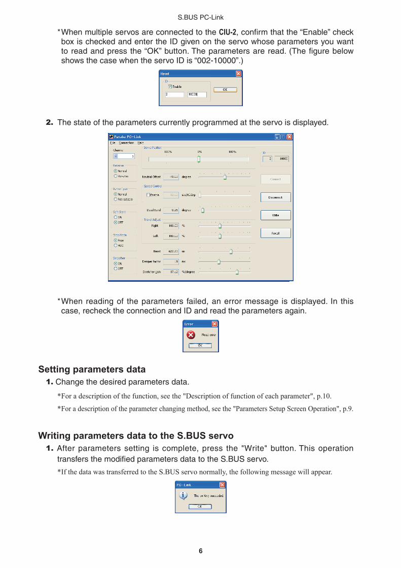
*WhenmultipleservosareconnectedtotheCIU-2,confirmthatthe“Enable”checkboxischeckedandentertheIDgivenontheservowhoseparametersyouwanttoreadandpressthe“OK”button.Theparametersareread.(ThefigurebelowshowsthecasewhentheservoIDis“002-10000”.)
2. The state of the parameters currently programmed at the servo is displayed.
*Whenreadingof theparameters failed,anerrormessage isdisplayed. In thiscase, recheck the connection and ID and read the parameters again.
Setting parameters data1. Change the desired parameters data.
* For a description of the function, see the "Description of function of each parameter", p.10.
* For a description of the parameter changing method, see the "Parameters Setup Screen Operation", p.9.
Writing parameters data to the S.BUS servo1.Afterparameterssetting iscomplete,press the "Write"button.Thisoperation
transfersthemodifiedparametersdatatotheS.BUSservo.
* If the data was transferred to the S.BUS servo normally, the following message will appear.

7
S.BUS PC-Link
2. Press the "Disconnect" button.
3. Disconnect the S.BUSservo.ThisoperationsavesthemodifiedparametersdatatotheS.BUSservofinally.
Reading parameters data saved at the PC1. Select the "Open" command from the "File" menu.
2.Afileopendialogopens.Select thefileyouwant toopen,andpressthe"Open"button.Whenreadingiscomplete,theparametersdataonthescreenischanged.
* At the time the file was read data is not transferred to the S.BUS servo. To write data directly to the S.BUS servo, check the read contents and transfer the parameters data to the S.BUS servo by pressing the "Write" button.
Saving parameters data to PC1. Select the "Save" or "Save As" command from the "File" menu.
* The "Save" command overwrites an existing filename. The "Save As" command saves the data under a new filename.
2.TheparametersfileissavedtothePCbypressingthesavebuttoninthedatasavedialog.
Initializing the parameters data1.Selectthe"Initialize"commandfromthe"File"menu.
* A confirmation message appears.
2.WhenYes (Y) isclicked, theparametersdataon thescreen ischanged to thedefault state.
* At the time the parameters data was initialized, the data is not transferred to the S.BUS servo. The S.BUS servo parameters data is initialized to the initial values by pressing the "Write" button.

8
S.BUS PC-Link
Discarding the parameter changes1.Clickthe“Recall”button.Orselectthe“Recall”commandofthe“Connection”menu.
* The displayed parameters return to the parameters read last.
9
S.BUS PC-Link
Parameters Setup Screen Operation
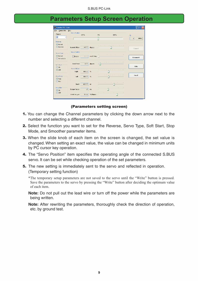
(Parameters setting screen)
1.YoucanchangetheChannelparametersbyclicking thedownarrownext to thenumber and selecting a different channel.
2.Select thefunctionyouwant toset for theReverse,ServoType,SoftStart,StopMode, and Smoother parameter items.
3.When theslideknobofeach itemon thescreen ischanged, thesetvalue ischanged.Whensettinganexactvalue,thevaluecanbechangedinminimumunitsby PC cursor key operation.
4. The“ServoPosition” itemspecifies theoperatingangleof theconnectedS.BUSservo. It can be set while checking operation of the set parameters.
5. The new setting is immediately sent to the servo and reflected in operation. (Temporary setting function)
* The temporary setup parameters are not saved to the servo until the “Write” button is pressed. Save the parameters to the servo by pressing the “Write” button after deciding the optimum value of each item.
Note: Do not pull out the lead wire or turn off the power while the parameters are being written.
Note: After rewriting the parameters, thoroughly check the direction of operation, etc. by ground test.
10
S.BUS PC-Link
Description of function of each parameter• ID
Displays the ID of the servo whose parameters are to be read. It cannot be changed.
• ChannelChannel of the S.BUS system assigned to the servo. Always assign a channel before
use.
• ReverseThe direction in which the servo rotates can be changed.
• Servo Type When theservo remainsstopped for30seconds, thedeadbandexpandsand
unnecessaryholdcurrentduetoexternal force iseliminated.Whenanewposition
signal enters, the normal mode is restored and normal operation is resumed. Select
the"Retractable"modefor theretractable landinggearservo. In thiscase,set the
TravelAdjustandtheSpeedControlatthesametime.
• Soft StartRestrictsoperation in thespecifieddirectionthe instant thepower is turnedon.By
makingthissetting,onlythefirstoperationwhenthepoweristurnedonslowlymoves
theservotothespecifiedposition.
• Stop Mode Thestateoftheservowhentheservoinputsignalislostcanbespecified.The"Hold"
mode setting holds the servo in its last commanded position even if using AM or FM
system.
• SmootherThis function changes smoothness of the servo operation relative to operation signal
changes.NormallyuseatSmoothsetting.Especially,select the"OFF"modewhen
quickoperationisnecessary.
• Neutral OffsetTheneutralpositioncanbechanged.When theneutraloffset is largevalue, the
servo's range of travel is restricted on one side.
• Speed ControlSpeeds can be matched by specifying the operating speed. The speed of multiple
servos can be matched without being affected by motor fluctuations. This is effective
forloadtorquesbelowthemaximumtorque.
However,notethatthemaximumspeedwillnotbeexceededevenifaspeedoverthe
maximumspeedoftheservoateachoperatingvoltageisset.
• Dead Band Thedeadbandangleatstoppingcanbespecified.If thedeadbandangleissmall,
the servo will operate continuously and the life of the servo may be shortened.

11
S.BUS PC-Link
• Travel AdjustThe left and right travels centered about the neutral position can be set independently.
• BoostThe minimum current applied to the internal motor when starting the servo can be set.
The dead band over which the servo does not operate even when a minute command
is applied can be reduced and the servo can be more accurately stopped at the target
position by setting this parameter to the optimum value.
• DamperMakesitdifficultfortheservotohunt(phenomenawhichcausetheservotooscillate)
bysuppressingovershootduetoinertiawhenalargeloadisapplied.Whenhunting
occurs due to the load even though the Dead Band, Stretcher, Boost, and other
parametersaresuitable,adjustthisparametertoavaluelargerthantheinitialvalue.
• StretcherSpecifies therangewhichadjusts the torquewhentheservoattempts toreturn to
thetargetpositionwhenthecurrentpositiondeviatesfromthetargetposition.Within
therangespecifiedherethetorquewhichattemptstoreturntheservotothetarget
position is output in proportion to the difference between the target position and the
current position. The left direction and right direction can be set independently.
Huntingcanbereducedbyusingthisfunction.

12
S.BUS PC-Link
Setting range of each parameter• Reverse: Normal/Reverse
• Servo Type: Normal/Retractable
• Soft Start: ON/OFF
• Stop Mode: Free/Hold
• Smoother: ON/OFF
• Neutral Offset: ±30˚ based on the default position
• Speed Control: Max.0.1sec/60˚~12sec/60˚
• Dead Band: 0.03~3.98˚
• Travel Adjust: 50~175%
• Boost: 0~1000.4µs
• Damper factor: 0~50ms
• Stretcher gain: 0~49.92%/degree
FUTABA CORPORATION Phone: +81 475 32 6982, Facsimile: +81 475 32 69831080 Yabutsuka, Chosei-mura, Chosei-gun, Chiba 299-4395, Japan
©FUTABACORPORATION2010,2(1)