fbi[t@> - duplex plusz · the purpose of the manual is to give you a brief ovewiew of the xl-2s...
TRANSCRIPT

.
XL-2S
Hookup and Installation Instructions
(Version 3.0)
FBI[t@>FIRE BURGMRY INSTRUMENTS, INC.
Subsidisy of Wtiay Corp.
149 Hleen Way, Syosset, NY 11791
N9513V1 4/96

THANK YOU for your purchase of the FBIIXL-2SILVER.
The purpose of the manual is to give you a brief ovewiew of the XL-2S control psnel, and provide instructionsfor installing a basic system. FBI I is always available to serve YOU. Our SALES and TECHNICAL SUPPORTstaff are av~lable to assist you in any way possible.
11
FOR SALES , REPAIRS
OR
TECHNICAL SERVICE ,
CALL TOLL FREE :
(800) 645-5430
Before you call Technical Service, be sure you:H Check the wiring diagram and verify your connections.
❑ Check all fuses.
❑ Assure that the transformer and backup battery voltages are supplying the proper voltage levels.
❑ Verify your programming information.
❑ Read this manual thoroughly.
❑ Consult the Troubleshooting Section of this Manual.
❑ Note the roper model number of this product, and the version level of known) along with anyFdocumen abon that came with the product.
❑ Have your company name and telephone number ready.
This information will allow us to service you more quickly and effectively. Please, remember to BE PATIENTwhile waiting on the telephone your call will be answered as soon as possible.
FOR YOUR CONVENIENCE, a System Planning Worksheet and a Programming Worksheet is included atthe back of this manual. These can be removed to help you record account information.

TABLE OF CONTENTS
WTRODUC~ON . . . . . . . . . . . . . . . . . . . ..6sYsmM~G ANDHooKuP . . . . . . . . ...7
W]ring Diagmm. . . . . . . . . . . . . . . . . . . 7
Terminal Corrections . . . . . . . . . . . . . . .8
Aux. Device Current Worksheet. . . ...10PC BOARD ~STALLA~ON . . . . . . . . . . . . . .11
Mounting the PC Board . . . . . . . . . . . ..llKEYPAD MOUN~G . . . . . . . . . . . . . . . . . . . 12
XL4600RM Keypad . . . . . . . . . . . . . ..l2~600SMKeypad . . . . . . . . . . . . . . ..l36805& 6615 Keypads . . . . . . . . . . . . ..l4
~YPAD LAYOUT . . . . . . . . . . . . . . . . . . . . . . 15Keypad Sounder . . . . . . . . . . . . . . . . . . .16
SYSTEM OPERATIONS . . . . . . . . . . . . . . . . . .17Power Up/System Reset . . . . . . . . . . . . . 17Arming . . . . . . . . . . . . . . . . . . . . . . . . ..l7Stay Arming . . . . . . . . . . . . . . . . . . . . ..l7Instant Arming . . . . . . . . . . . . . . . . . . ..l8Stay-Instant Arming . . . . . . . . . . . . . . ..l8Reset . . . . . . . . . . . . . . . . . . . . . . . . . . . .18Bypass . . . . . . . . . . . . . . . . . . . . . . . . ..l8Quick Byp=s . . . . . . . . . . . . . . . . . . ...19Auto-Unbypaas . . . . . . . . . . . . . . . . . ..l9Manual Unbypass . . . . . . . . . . . . . . . ..l9User Code Pregmmming. . . . . . . . . . ..l9User Deletion . . . . . . . . . . . . . . . . . . . ..2OKeypad Emergency Conditions. . . ...20
QUICK COMMAND MODES . . . . . . . . . . . . ..2OQuick Arming . . . . . . . . . . . . . . . . . . ..2OQuick Force Arrrring . . . . . .. . . . . . . . ..2OToggle Chime . . . . . . . . . . . . . . . . . . ..2OOn-line Download . . . . . . . . . . . . . . . ..2O
~STALLERMODES . . . . . . . . . . . . . . . . . ...21Installer Keypad Programming. . . . ...21System Default . . . . . . . . . . . . . . . . . . ..2lUser Code Default . . . . . . . . . . . . . . . ..2lSystem Log View . . . . . . . . . . . . . . . . ..2lUnattended Download . . . . . . . . . . . . ..2lOn-line Download . . . . . . . . . . . . . . ...22
SYSTEM PROGRAMM~G . . . . . . . . . . . . . . .22PROGRA~G QUES~ONS . . . . . . . . . ...23
01 Primary Telephone Number . . . . . ..2302 Secondary Telephone Number . . . . .2303 Callback Telephone Nnmber . . . . ..2304 Dialer Options . . . . . . . . . . . . ...2305 KeWad Cmrditions . . . . . . . . . . . . . .2506 System Timemrts. . . . . . . . . . . . . . 2807 Misc. System Options. . . . . . . ...2908 Accmrnt Number l . . . . . . . . . . . . ..3O09 Account Number 2 . . . . . . . . . . . . ..3l
ZO~ PROG~G . . . . . . . . . . . . . . . . ..3l10 Zone Number l . . . . . . . . . . . . . . ...33llZone Number 2 . . . . . . . . . . . . . . ...3312 Zone Number 3 . . . . . . . .. . . . . . . ...3313Zone Number 4 . . . . . . . . . . . . . . ...3314Zone Number 5 . . . . . . . . . . . . . . ...33lSZmre Nmnber 6 . . . . . . . . . . . . . . . . 3416ArnbusMAC Loss . . . . . . . . . . . . ...3417Panic&w Battery . . . . . . . . . . . ...34180petiClose/CS Test . . . . . . . . . . ...3419BypassRestore~rouble/Cancel. ..3420 Ke~ad FireKeypad Auxili~ . . . . . 3500 Installer Code . . . . . . . . . . . . . . ...35
DATA ENTRY WA LED& LCD KEYPADS. 36How to Enter Programming Mode. . ..36What You See On the LED Keypad. ..36What You See On the LCD ICeypad.. .37Howto Enter Data . . . . . . . . . . . . . . ...37Exit System Pro~am Mode . . . . . . . ...38Summary of System Programming . . . . 38Zone Descriptor Programming. . . . ...39
SYSEMDEFAULTS . . . . . . . . . . . . . . . . . . ..4OSUMMARY OF KEYPAD FUNCTIONS....41
User Functions . . . . . . . . . . . . . . . . . . . 41Installer Modes . . . . . . . . . . . . . . . . . ..4l
APPENDIX A - CS REP. FOMTS . . . . . ...42Standard (3Xlor4Xl) . . . . . . . . . . ...42Extended (3Xlor4Xl) . . . . . . . . . . ...43Part. Ext. (3Xlor4Xl), . . . . . . . . . ...433X20r4X2 . . . . . . . . . . . . . . . . . . . ...43
APPENDIX B - TROUBLESHOO~G . . . ...44SYSTEM PLANN~G WORKS~ET . . . . ...45
ZOneInformation . . . . . . . . . . . . . . . . ..4SUser Cdes . . . . . . . . . . . . . . . . . . . . . ..4SKeWads . . . . . . . . . . . . . . . . . . . . . . ...45
SYSTEM PROGRAMING WOKS~ET. ..46WARN~G LIMITA~ONS STATEMENT . ..47WARRANTY . . . . . . . . . . . . . . . . . . . . . . . . ...48FCC STA~MENT . . . . . . . . . . . . . . . . . . . ...48
XL-2SHookup& Instillation MammlPage 3

XL-2S TO XL-2 COMPARISON
The XL-2S is an enhanced version of the XL-2 control panel. Some new features have been added and othershave been modified. The following ia a quick comparison.
x~
Unattended Download (Installer Mode 3)
On-line Download (Installer Mode 4 or # 4)
2 Entry Timers (program quest. #06)
Swinger Shutdown - Bell and Dialer Lockout(program quest. #04)
&!g%AtTfL7.%%Y5K2) - ‘ ‘igit ‘ntw
Last 2 Alarme Event Histo ~- not clearedby user code (Installer Mode )
Smoke Power or Programmable Trigger Output(program quest #07)
CS Test ~mer -1 Day, 7 Da 27 Day, 60 Dayor 90 Day (program quest, #~})
CS Teet Key ad Rtn back Programmablex?as Silent or udlble program quest. #05)
Cancel Cods (program quest. #l 9)
End User Chime ON/OFF Toggle (#6)
European Ring Detect (program quest. #07)
Exit Error Warning (always enabled)
Restore Follows Bell or Loop (program quest. #05)
Bypass InStay. Any Controlled Zone can beBypassed In Stay Mode (program quests. #l O-15)
S stem Stabilization on Power Up -to Eliminatedtion Detector FalaeAlarms
Quick Commands (Quick Arm, Quick ForcedArm & Quick By ass) enabled separately
$(program quest. 05)
XI -2S FFATURF CHANGFSSystem Wide Restora Code Enable(program queet. #19)
Standard Download Only
Standard Download Only
1 Entry Tmer
Bell Lockout
Multiple digits required
Alarm Memo~ (cleared by user code)
Smoke Power Only
CS Test Timer 1 Day Only
CS Teat Keypad Rngback always Audible
NONE; Restore Code Only
NONE
NONE
NONE
Restore Follows Bell Only
Interior Zones Bypassed Only in Stay Mode
NONE
Quick Arm is enabled separately butQuick Forced Arm & Quick Bypasa enabledtogether
Restore Codes selectable by each zone
XL-2S Hookup& installation ManualPage 4

XL-2S, ve~ion 3.0 TO XL-2S, vemion 2.0 COMPARISON —
The following changea are hated for those fsmihar with the previous version (2.0) of this control.
AR FFATU~
Zones Re ort Restores inde endent of AC Lossfi !& Low Ba ery (program ques. #04)
Zones Re ort Restores along withtAC Leas Low Battery
Irretant Armin avsilsble by itself?(program ques. W5)
Instant Arming NOT availsble by itself
Hre Non-verification Trigger Typa(program quest. #07)
Not available
:;:;FJ:z?:tjger TypeNot available
@g:?;tt2:8?rNot available
Auto-unbypass ia slwaye enablad
Trig er Typee deleted: ~ne Seizure, Rrs Bell &Co?e Reset
LCD Zone Descriptors NOT defaulted
Stay/lnatant Enable moved to program quest. W5,location 2
Ueer 5 Arm Onl Enable moved to programquest. #05, localon4
Burgla Bell Tfigger Type entry in progrem7quest. # 7, Iocabon 4 la dlgtt 3
CS Test Enable in pro ram queet. #04, location 4Pdeleted; CS Test diseb e edded to CS Test Time m
program quest. #07, location 3
Inetaller Code Default changed to “246V
Xl 2S. ver 2.0 S. IMILAR FEATUR SE
Auto-unbypass programmable
All Three Trigger Types available
LCD Zona Descriptors are defaulted
Stay/Instant Enable found at programquest, #05, Iocabon 4
User 5 Arm Orsl Enable. found at1program quest. 05, location 2
Burgla~ Bell Tri er Type ent~ inprogram quest~87, location 4
CS Test Enable in program quest. #04,location 4
Installer Code Default = “2121”
XL-2S Hookup& Instillation Manuel—
Page 5
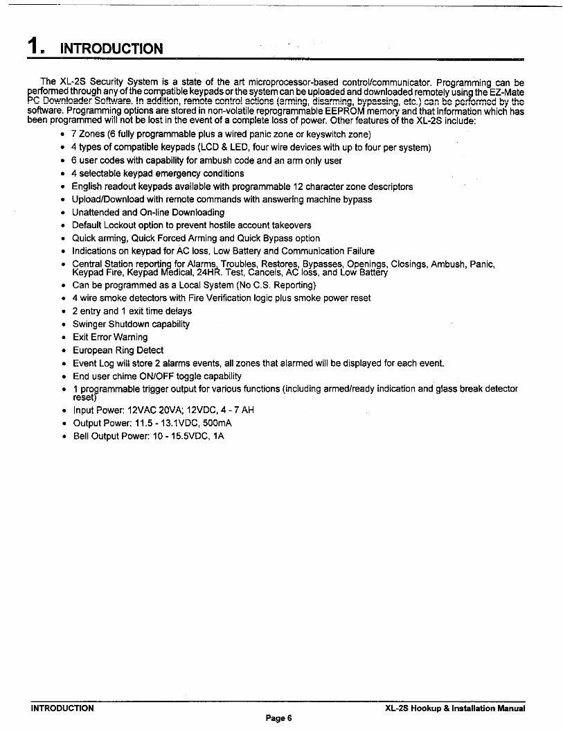
1. INTRODUCTION
The XL-2S Security System is a state of the art microprocessor-based contro~communimtor. Programming ~n beperformed through any of the compatible keypads or the system can be uploaded and downloaded remotely usin the EZ-Mate
$PC Downloader SoWare. In addition, remote control actiona (arming, disarming, bypaasing, etc.) can be pe ormed by thesoftware. Programming options are stored in non-volatile repmgrammable EEPROM mamory and that information which hasbeen programmed will not be lost in the event of a complete Iosa of power. Other featurea of the XL-2S include
.
.
.
.
.
.
.
.
.
.
.
.
.
.
.
.
.
.
.
.
.
.
.
7 Zones (6 fully programmable plus a wired panic zone or keyswitch zone)
4 types of compatible keypads (LCD& LED, four wire devices with up to four per system)
6 user codes with capabili~ for ambush code and an arm only user
4 selectable keypad emergency conditions
Engtish readout keypads available with programmable 12 character zone descriptors
Upload/Download with remote mmmands with answering machine bypass
Unattended and On-line Downloading
Default Lockout option to prevent hostile account takeovers
Quick arming, Quick Forced Arming and Quick Bypass option
Indications on keypad for AC loss, Low Batte~ and Communication Failure
Central Station reportin for Alarms Troubles, Restores, Bypasses, Openings, Closings, Ambush, Panic,2Keypad Fire, Keypad edlcal, 24Hk. Test, Cancels, AC loss, and Low Batte~
Can be programmed as a LOMI System (No C.S. Repoting)
4 wire smoke detectors with Fire Verification logic plus smoke power reset
2 entry and 1 exit time delays
Swinger Shutdown capability
Exit Error Warning
European Ring Detect
Event Log will store 2 alarms events, all zones that alarmed will be displayed for each event.
End user chime ON/OFF toggle capability
1 programmable trigger output for various functions ~ncluding armed/ready indication and glass break detectorreset)
Input Power 12VAC 20VA, 12VDC, 4-7 AH
Output Power 11.5- 13.IVDC, 500mA
Bell Output Power 10- 15.5VDC, 1A
INTRODUCTION XL-2S Hookup& Installation ManuslPage 6

~. SYSTEM WIRING AND HOOKUP ——-
2.q . SYSTEM WIRING DIAGRAM
CONNECTIONS’ FOR HOUSEHOLD FIRE/BURGLAR AWRM SYSTEM (PER UL STANDARDS UL985 AND ULI 02!3)
XL-2S
I
IIIIIIiIIII
IIIIIIIII
L ------ ----J
“, ,MS,ALL1tONS REQUIRE LISTEDEN&OF-LINE DEVICE, USE RESISTORFROM EOU2 KIT, 1~. FOR LISTINGMARK ON ITEM.
mPm,-...
(SEENWf 7)Omm
,s,, “m, $3, 1. ‘MEELCO
SYSTEM STABIL~TION MODE: Upon initial powerup of the syetem, all of the lights on the LED keypad(e) will
1
go ON and then go OFF for approximately 2 min. 10 eece andlor the LCD keypad(e) will display STAND BY! for
approximately 2 min. 10 aece. This occurs on a total powerup, eyatem reset or after completion of syetemprogramming. If the total system power ia lost then upon power restorsl, the system will return to the previollaerming state. The 2 min. 10 aeca. interval ie ueed to allow motion detectors ~nterior zones) to stakdlize onpower up in order to prevent falae alarma. THIS OPTION CAN BE DISABLED BY PU~lNG A MOMENTAFIYJUMPER BETWEEN TERMINAL 13 AND 12 ON POWER UP. IF DISABLED, THEN THE POWER UP RESET TIN!EIS APPROXIMATELY 5 SECONDS. This ie a normal condition.
XL-2S Hookup& installation Wnual SYSTEM WIRING AND HOOK=Pags 7

—.
2.2. TERMINAL CONNECTIONSTERMINALS DESCRIPTION1(+) & 2(.) Zone 1 (Requires 2,2K EOL resistor)3(+) & 2(.)
[Default = DEMY]Zone 2 (Requires 2.2K EOL resistor) [Default= INTERIOR]
4(+) & 5(.) Zone 3 (Requires 2,2K EOL resistor) [Dafault = PERIMETER]6(+) & 5(-) Zone 4 (Requires 2.2K EOL resistor)7(+) & 8(.)
[Default = PERIMETER]Zone 5 (Requires 2.2K EOL resistor)
g(+) & 8(.)[Default = PERIMETER]
Zone 6 (Requires 2,2K EOL resistor) [Default = PERIMETER]
ZONE INFORMATION:
Normally closed devices may be wired in series and/or normally open devicesin parallel with the 2.2k ohm end of fine resistor on all zones (Refer to the wiringdiagram). The standard loop response time is 280 ms on all zones. The factorydefault values for each zone is listed in the table above, however any zone canbe programmed for the following types: Delay, Perimeter, Interior, Fire, 24 Hr.Alarm, or 24 Hr. Trouble. Further explanation of the zone types @n be found inthe System Programming section of this manual. NOTE: Loop response isdefined as the minimum time required for a fault to trip a zone.
8&10
11
12131415
PANIC CIRCUIT OR KEYSWITCH :
Normally Open PANIC circuit. This hardwired panic is a 24 hour zone which @nbe programmed for silent or audible operation. The panic circuit will activate witheach violation, therefore a latched device is not recommended. A momentarydevice is recommended. For UL installations, the panic switch connected tothese terminals is to be located no more than 3 feet from the control unit, withno intewening barriers (this is a supervision requirement only). If the keyswitchoption is selected (see programming question 05, location 2), then eachactivation of the keyswitch will arm and disarm the system.
NOTE: E.O,L. resistor is not required on this zone and is not supervised. Thiszone does not report restore codes, If a supewised zone with restore reportingability is desired, then program one of the 6 zonas as a 24 Hr. Alarm. If used asa keyswitch, then triggers are available for either an arming or ready statusindication (see programming question 7, location 4).
EARTH GROUND:
Connect this grounding lug to a cold water pipe utilizing #18AWG wire at adistance of no greater than 15 ft. Use a noncorrosive metal strap firmly securedto the pipe to which the lead is electrically connected and secured. If thepremises pipes terminate in PVC, this terminal must be connected to a six(6)foot grounding rod.
KEYPADS:
A maximum of4 keypads, either XL4600RM, XL4600SM, 6615, or 6805, maybe wired to these terminals, The connections are as follows; 12 (BLACK =negative), 13 (YELLOW = data in),14 (GREEN = data out) and 15 (RED =positive power). Each keypad draws approximately 30mA. Maximum keypadlength is 500 feet using 22 gauge wire. NOTE: In some installations, it may benecessary to use shielded wire to prevent radio frequency interference.
12(-)&15(+) REGULATED POWER (11.5 - 13.lVDC) :
The total regulated output power for motion detectors and other etiernaldevices is 500M at 11.6- 12.5V for residential applications, or 12.0- 12.5V forcommercial applications, with less than 100 mVPP ripple. The total regulatedoutput capacity of the XL-2S includes the power available from these terminals(15 & 12) as well as the power used by the keypads and smoke detectors.Therefore, to determine the total power available from these terminals subtractthe power consumed by the keypads and smoke detectors.
SYSTEM WIRING AND HOOKUP XL-2S Hookup& lns~llation ManualPage 8

SMOKE DETECTOR POWER OR TRIGGER OUTPUT:15 (+)16 (-) SMOKE DETECTOR POWER This system will accept 9.5- 12VDC four (4)
wire smoke detectors only. Approximately 50ti of current is available at thf?seterminals for powering all detectors and an E.O.L. relay FBII model 620. For ULinstallations sea wiring diagram for hookup.
These terminals adhere to the fire verifi~tion and reset logic which is explainedin the zone types section of this manual, Manual reset of smoke detector powercan be accomplished by entering a vahd user mde after clearing alarm memoyor using the asterisk ~) key.
TRIGGER OUTPUT These terminals can be used for a trigger output. Seeprogramming question #07, location 4 for vakd tfigger types. NOTE: Unl{3ssotherwise specified, the trigger output is normally floating and actively sinks onactivation.
17181920
21(+)
22(+) & 23(-)
24& 25
TELEPHONE LINE:
Connect the model 368 cord as follows 17 (GREEN = Telco Tip), 18(RE[) ❑
Telm Ring), 19(BROWN= Home Tip), 20(GRAY= Home Ring). Insert the pluginto an USOCRJ31 X jack (or a CA31A jack for Canadian installations).
The FCC registration number is (AE398E-69554 AL-E), and the tin!~erequivalence is (0.OB). The system should not be conneded to party lines, orcoin operated phones.
If this mntrol panal will be used for uploading, downloading or remote commelndapplications, the telephone tine connected to the control panel must not beshared with a fax machine or modem. Furthermore, this device should not bemnnected to a phone line which has call waiting, unless the =11 waiting internJptnumbers are programmed into the panel diafing sequence.
CONSTANT DC POWER:
This terminal detivers constant unregulated 10.0-15.5VDC power for devicesrequiring a constant power such as VS279. It is connected to a bell fuse (F2).NOTE: Constant power for these devices ~n also be obtained by splicing theRED (+) battery lead with an in-hne fuse of 3 Amps.
BELL OUTPUT
The total output power available for sounding devices is 1 amp at 10.5-1 !j.5VDC for residential applications, or 12,0 -14,4 VDC for commercial instsllaticlns(750 mA for UL installations), These terminals will deliver CONSTANT outputon BURGLARY, AUDIBLE PANIC and BELL TEST. On a FIRE condition, aPULSED output will be generated. There are separate bell cutoff timlesprogrammable for Burgla~ and Fire conditions within the programmingsequence. For UL Household Fire Warning System installations, the speaker isrequired to be mounted indoors for best auditihty. Also, for UL installations, btseonly one speaker, NOTE: Before connecting sounding devices please consulttheir specifications for proper current draw. Otherwise, the bell fuse (F2) maybe blown.
TRANSFORMER
Connect the 12 VAC 20VA transformer, utilizing 18awg wire at a distance notto exceed 15 feet from the panel, to an unstitched 120 VAC outlet.
Do not use any other transformer since this may result in improper operation ordamage to the unit.
The AC/LOW BAT LED on the keypad will remain ON, while AC power ispresent. If an AC loss occurs the AC/LOW BAT LED will turn off immediatc!ly.If AC remains OFF for 15 minutes, the system will pulse the keypad buzzer andtransmit to the central station, if programmed. THE KEYPAD BUUER CAN 13ESILENCED by ent~ of any valid user code. men AC restores the AC/LCIWBAT LEO will light immediately, and a restore code will be reported, ifprogrammed.
XL-2S Hookup& Installation Manual——
SYSTEM WIRING AND HOOKUPPage 9

BACKUP BATTERY The RED(+) and BMCK(-) flying Ieada must be connected to a 12 VDC 4%AHGELL CELL, to serve as backup power in the event of AC loss.
Abattery testoccurs approximately every 4.5 minutes, Low battery conditionoccurs at nominal IIVDC. The keypad AC/LOW BAT LED and buzer willPULSE SLOWLY when a low battey condition is detected. The system reportsthis condition to the CS if programmed. Batte~ restoral will occur MTHIN 4,5minutes, at the NEXT battey test. THE BUZER MAYBE SILENCED by entryof any vakd user code.
GROUND START Ground stad Hpabihty can be added to the system through addition of the FBIIModel 117 module, Consult the 117 Installation Instructions for hookupinformation. With this device some systems can obtain dialtone where it is notavailable. At the moment telephone line seizure occurs, the Telco Tip ismomenta~ connected to earth ground to access dial tone. NOTE: The 117module has not been tested for use in UL installations.
2.3. AUXILIARY DEVICE CURRENT DRAW WORKSHEET
r ,,. , , 1
SmokeOetectorGlasscreak Oetector I I I
1II 1 1
11
NOTE: ‘ Only appties if device is powered from control terminals 15 (+) & 12 (-).‘“If using devices such as PIRs, smoke detectors, etc., refer to the specifications for that particular
device’s current draw. If the total current draw exceeds 500W, then use an additional power supply.
SYSTEM WRING AND HOOKUP XL-2S Hookup& installation ManualPage 10

3. PC BOARD MOUNTING
3.1. Mounting the PC BoardBefore mounting the printed circuit board, be cstin that the appropriate metal knockouts have been removed, DO N(3T
ATTEMPT TO REMOVE THE KNOCKOUTS ARER THE CIRCUIT BOARD HAS BEEN INSTALLED.
1. Hang the three mounting chpa on the raised cabinet tabs. Observe proper clip orientation to avoid damage to the clipwhen mounting screws are tightened and to avoid problems with insertion and removal of the PC board.
2. lnsetithe topofthe circuit board intothe slots atthetop of the~Mnet. Makesure thatthe board rests inthe slots asindicated in the diagram shown below.
3, Swing the base of the board onto the mounting clps.
4. Place the washer provided over the wire jumpers located within the middle of the PC board. Secure the PC board tothe middle mounting clip of the enclosure through the washer using the screw provided.
5. Secure the remaining sides of the PC board to the enclosure using the screws provided,
OF CLIPINeTALLATION: REQUIREO DETAILSIOEVIEWA. CABINETTAB OFCLIPANO❑OARD
WTHOUT CLIP INSTALLEOB. CABINETTAe
WTH HANGINGCLIP
NOTE: The front face of the enclosure can be mmpletely removed from the enclosure to gain unrestricted access to thecontrol panel during installation. The front of the enclosure can be removed as follows
1) Open the enclosure to its fully efiended position (approx. 90 degrees)
2) Lift the control panel door and remove the door from the enclosure.
XL-2S Hookup& installation Manual PC BOARD MOUNTNGPsge 11

~. KEYPAD MOUNT!NG
4.f . XL4600RM METAL KEYPADFLUSH MOUNTING USING DOUBLE GANG BOX
Q:‘.
.,, ‘. ....,, . . .
. . .
. . . . . . . .
. . . .
l- Create an opening and mount aatandard doublegang box,
2-Secure keypad to double gang box as shown indiagram below. NOTE: The double gang box shouldbe mounted flush with the wall in order for the keypadscrews to fit.
NOTE: For UL installations, mount the XL4600RM toan earth grounded outlet box.
FLUSH MOUNTING WITH MOUNTING RING (Using the XL4600TR)1- . ml.. 1- Create the desired opening where keypad is to be
mounted, using the inside of the mounting ring as atemplate. NOTE: This opening should be madebetween studs.
2-Secure mounting plate to wall through the four outerholes using suitable mounting hardware (notprovided).
3- Connect keypad wiring to control panel and securethe keypad to the mounting ring using the four paintedscrews provided.
““..USURFACE MOUNTING (Using optional XL4600RMBX)
~: ‘ : “ti
1- Depanding on type of installation run the keypadwifing out of the rear, top bottom or sides of thebackbox.
2- Attach backbox to wall at desired height
3- Insert XL4600RM keypad into backbox and securewith the four screws provided.
MOUNTING KEYPAD IN CONTROL PANEL ENCLOSURE1- Remove keypad knockout from front of metal box
n’
0. .0 enclosure as shown.
2- Insert XL4600RM into opening from front of
m
enclosure.
::: ❑ mwa 3- Secure keypad to enclosura using the four paintad
;:: mmm Q metal screws and nuts provided... amDg.’.- mmma
KEYPAD MOUNTING XL-2S Hookup& lnstiUation ManualPage 12

4.2. XL4600SM KEYPADThe XL4600SM Keypad maybe surface mounted in the following ways
A, Mrectly to a mntrol panel having a keypad cutout on the front of its enclosure.
B. Directlv to a single or double aana electrical iunction box.
C. Direct~ to a wa~ or other surf~ca~ “
L JLOT FORcO=R SECURINGs ew
‘0’’’0””’ ACWER PRY~FF SLO~ (2)UO REMOVECOVER, INSERTSWLSCRE~RER BME MD WST.I
Diagram 2 BOTTOM VIEW OF KEYPAD
%5?o
N6054
(–~
WRINGOPENING
(FORCOWWED
MRINO)\ /
.
1HOLES “B” (2)(FORMOUWIW TOSIWLE WWEECTRl~ BOX)
IIHOLES *CA,,OR “B”(WN BE USEDFORWAN MOUNTI%)
t
SNAP H~KS (2)(FOR~L~ffi CO~RSLMR EWE)
—
MST FOR COVER - \ BRWK.AWAY RISS (4)SECURING SCREW (OmlW) (F~ -ED ~Rlffi EMRY.)
Dagram 3 REARMOUmNG PLATE
1. Remove the keypad rover aasembly tiom the rearmounting plate. Insert a small screwdriver blade in theCOVER PRY-OFF SLOTS at the lower edge of thekeypad (see Diagram 2 ) and tist to pry off tha roverassembly.
2. Mount the rear plate (see Diagram 3),
NOTE: The plate is correctly oriented when its f~artnumber, molded into the plastic, is upright,
A. MOUNTING DIRECTLY TO CONTROL PANELENCLOSURE:
If the control panel has a keypad cutout on the frontface of its enclosure, remove the cutout and mount theplate to the enclosure’s face via HOLES “A ( seediagram 3) and the four screws and nuts provided.
NOTE: The XL2B attack-proof enclosures does notcontain a keypad cutout,
B. MOUNTING DIRECTLY TO AN ELECTRICALJUNCTION BOX
The plate cen be mounted directly to a single or doublegang electrical junction box. Use the screw holesprovided and HOLES “W for a single gang box orHOLES “W for a double gang box.
C. MOUNTING DIRECTLY TO A WALL OR OTHERSURFACE
Provide a wirino hole in the mountina surface. Positionthe plate’a W~RING OPENING o;er the hole :Indmounting plate, using HOLES “A and/or “B” inconjunction with appropriate mounting hardware (lnotprovided) for the type of surface.
3. Complete the keypad wiring as required for Ithecontrol with which the keypad is to be used.
4. Replace the keypad cover assembly on the r{?arplate. Starting at the upper edge of the plate, engelgethe plate’a two HOLDING HOOKS (see diagram 3) intothe recesses provided for them inside the upper eclgeof the cover assembly and snap the lower edge of lthecover assembly and snap the lower edge of the co)(eronto the two SNAP HOOKS at the lower edge of Itheplate.
NOTE: (Optional) If desired, cover and plate can befurther secured together by inserting a screw(provided) into the SLOT at the keypad’s lower ed(le.
NOTE: When surface mounting the keypad, and using straws with heads larger than the screws provided with the unit,place electrical tape over the screws to prevent them from interfering with the keypad operation. In the future the back pkateof the keypad will provide additional countersinking for xrews with Iargar heads.
XL-2S Hookup& Insbllation Manual KEYPAD MOUNTlitiPage 13

4.3. MOUNTING 6805 and 6615 KEYPADSKeypad mounting is identical for both the 6615 LED and 6805 LCD versions. Keypads can be surface mounted or flush
mounted as described below, NOTE: After mounting the 6805 LCD Keypad at e e level, you can adjust the &splay intensityJlevel to suit the user by adjusting the intensity control located behind the keypa door.
SURFACE MOUNTING
11.11........-.. M..-.. E..- ......1 I
RECESSED MOUNTING
2 1
1. Select a mounting location and place the rear plateof the keypad on the wall. Mark the location of thecutout for the keypad wiring cable.
2- Createa keypad opening Connect the keypedwiring to the control panel w/4-wire connector.
3- Plain the keypad wiring through the cutout andsecure the back plate to the wall (see diagram).
4-Connect the keypad wifing connector to the keypadand place the keypad on the mounting plate attachedto the wall.
5- Secure the keypad to the rear mounting plate byattaching the 5/6 inch screw provided in the lower hole,located behind the keypad door.
1- Select a mounting location. For racessed mounting
this must be betwaen two studs, The rear mountingplate is not used for recessed installation.
2- Create an opening in the wall exactly 4 inchas highby 5 13/16 inches wide.
3-Turn over the keypad and ramove the Phillips headscrew ~teml ondiagram) intheupper left hand sideof the keypad printed circuit board. NOTE: This screwis located immediately to the Iaft of the keypadconnector.
4-Attach the black metal mounting strap to the rear ofthe keypad as follows (see diagram~
- Face the pointed end of the mounting strap facing thakeypad front. This will be usad to latch onto tha insideof the wall.
- Place the small white plastic spacer underneath themounting strap. Secure themounting strap using the5/8 inch Phillips head screw (supplied) and the plasticspacartolosation 1.
- Secure the other end of the strap (location 2 ondiagram) to the white plastic opening using the Phillipshead screw removed in step 2.
5-Connect the white plastic tab into the round openingimmediately behind the keypad door. Place the longerPhilhps head screw (included) through the openinginside the keypad door and begin to tighten the screw.Tighten the screw and leave the tab in a down position.
6- Run the kaypad wiring to the control panel andattach the wiring to the keypad.
7- Place tha keypad into the wall opening with the sidecontaining the black metal strap first until it grabs theinside of the wall.
8- ARer inserting the side of the keypad with the metalstrap, insert theother side into the opening until theentire keypad is firmly in the wall.
9- Tighten the screw inserted in step 5.
KEYPAD MOUNTING XL-25 Hookup & Instslletion ManuslPage 14
~. KEYPAD UYOUT
3\*I
7
8
9
10
51 ~ XL4600RM KEYPAD
*76615 KEYPAD b
XL4600SM KEYPAD
&I
----,
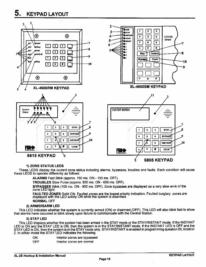
{ 6805 KEYPAD1) ZONE STATUS LEDS
These" LEDSdisplay thecurrent zone s@tus including alarms, bypasses, troubles and fsults. Each wndition will causethese LEDS to operate differently as follows
ALARMS Fast Blink (approx. 150 ms. ON -150 ms. OFF).
TROUBLES Slow Pulse @pprox. 600 ms. ON -600 ms. OFF).BYPASSES Wnk (100 ms. ON -900 ms. OFF). Zone bypaases are displayed as a very slow wink of thezone LED hoht,
FAULTED ~ONES Sotid QN. Faulted zones are the,lowest priority indi~tion. Faulted burglary zones aredisplayed with the LED solrdly ON while the system ISdisarmed.NORMAL OFF
2) ARWDISARM LEOThis LED indi~tes whether the system is currently armed (ON) or disarmed (OFF). This LED will also btink tist to show
that alarms have owurred or btink slowly upon failure to communi~te with the Central Station.
3) STAY LEDThis LED dsplays whether the system has been armed in the STAY mode or the STAY/lNSTANT mode. If the INSTANT
LED is ON and the STAY LED is ON, then the system is in the STAY/l NSTANT mode. If the INSTANT LED is OFF and tlheSTAY LED is ON, then the system is In the STAY mode only. STAY/l NSTANT isenabled in programming question 05, lowtil~n2. In aither mode the STAY LED indicates the following:
ON Interior zones are bypassed
OFF Interior zones are normal
XL-2S Hookup& Installation Manual——
KEYPAD LAYOIJTPsge 15

4) INSTANT LEDThis LED displays whether the system has been armed in the STAY/l NSTANT mode, meaning that the system ia currently
armed, all delay zones are instant and all interior zones are bypassed, NOTE: Sae programming question 05, lo~tion 2,
ON Delay zones are currently instantOFF Delay zones are normal
5) AC/LOW BA~ERY LEDThis indicator fight displays the current power status of the panal as follows
ON AC is presentOFF No AC, running on batteV backupSlow Blink Low battey condition detected
6) RMDY LEDThis LED displays whether the system is ready for arming. The READY tight is common to all BURGLARY ZONES with
the following indications
ON System raady to be armed
OFF System not ready to be armedSlow Blink Indimtes Installer programming modeFast Bhnk Alarm Memory Mode
7) STAY BU~ONThe STAY button enables arming the system, excluding zones programmed as interior zones. This will provide efienor
protection of the location while allowing full access throughout the interior.
8) BYPASS BU~ONThe BYPASS button is used to temporarily exclude protection to a specific zone.
9) INSTANT BU~ONThe INSTANT button enables arming the system eliminating enty/exit delays. If anabled with tha STAY button, it enables
arming the system in the STAY/l NSTANT mode. NOTE: The INSTANT modes are enabled in queetion #05, location 2.
10) CODE BU~ONThe CODE button is used to enter the installer programming mode and entry of user codes,
11) LCD DISPLAYThe LCD display shows the current status in a two fine by Welve format.
12) KEYPAD AUXILIARY KEYS (XL46QOSM KEYPAD ONLY)Pressing the two keys (top & bottom) labeled “P at the same time initiatee a CS transmission, if programmed, of PANIC,
AUXILIARY or FI RE, annunciates the keypad sounder and turns on the bell output. If not programmed to transmit, these keyscan only result in a local warning as follows (see question 05, location 1):
Keypad Souder - Steady for PANIC, Pulsing for FIRE and AUXILIARYBell Out ut - Steady for PANIC, Pulsing for FIRE
PNOTE: See ques Ion #05, Ioaction 1 for alternate auxiliary keys
5.1. KEYPAD SOUNDERThe kaypad sounder annunciates differently to indicate tha following conditions
CHIRP - Keypad sounds a short chirp to confirm each keystroke.STEADY - The keypad will make a steady sound during ent~ time, and/or during burgla~ alarm.CHIME - steady 1 second tone (SYSTEM DISARMED ONLY).$$fKaNs~~o~~DGE - Upon successful ent~ of a certain commands the system will sound for approximately
PULSING - A ulsing sound (approximately half a second ON then OFF) indicates a trouble rendition such asEAC loss, Low atterv, or ~re Zone.
NEGATIVE ACKNOWLEDGMENT - U on entry of an ille al command the keypad will sound four short
{f3bee s. For example, if attem tlng to de mea new user an the maater user IS not entered, four short beeps
Ewill e mede indicabng that t e command wes unsuccesshl,SOUNDER RINGBACK - Several short beeps to indicate suc@ssful mmmunicstion to the Central Station,This occurs for all signals, excludlng ambush and silent zones.FAST PULSING SOUNDER- Sound enerated duti,ngent~ time period AFTER an alarm rendition has
?occurred and,the system reached bel cutoff. A pulslng sounder will follow the bell output on Fire conditions.Trouble conditions also generate a pulslng sounder and may be silan=d through ent~ of a valid user rode,
KEYPAD LAYOUT XL-2S Hookup& Ins@llation ManualPage IS

NOTE: The keypad ia nors~peratiorsal if none of the LED’s sre Ht and the keypsd does not beep wfrsn keye tirepressed. This is sn indication thst sewice is required. Consult the troubleshooting section of this msnual. 16. SYSTEM OPEWTIONS ——
6.1. POWER UP/SYSTEM RESETUpon initial powerup of the system, the LCD keypad will display STAND BY! for approximately 2 min. 10 sees. and on the
LED keypad all of the fights will go ON and then go OFF for approximately 2 min. 10 seca. This omurs on a total powerup,system reset or after mmpletion of system programming. If the total system power is lost then upon power reatoral, the sysitemwill return to the previous arming state. The 2 min. 10 se=. interval ia used to allow motion detectors (interior zones) tostabilize on power up in order to prevent false alarms, This option mn be tisabled by puting a MOMENTARY jumper betweenterminal 13 and 12 on power up, If disabled, then the power up reset time is approximately 5 semnds.
6.2. ARMING THE SYSTEMThe system can be armed only if all burgla~ zones are good (not faulted). On LED based keypads this requires that the
READY LED is on.
On LCD keypads the following message will appear
m1 !
TO ARM: Enter any programmed four digit user. NOTE: The factory default for user #l is 1234.
The ARMED LED will hght and the user may exit through an exi~enby zone for the time period programmed as the exitdelay. The system =n be armed without the backup battery being mnnected, however the AC/LB light will flash.
LCD Based keypads will display:
m6.3. STAY ARMING
TO ARM: Press the STAY BUTTON followed by a four digit user rode.The ARMED and STAY LEDs will tight on LED based keypads.
LCD besed keypads will display:
mThe system is armed at this time with all programmed interior zones excluded.
6.4. STAY/lNSTANT ARMING
TO ARM: Press the INSTANT then STAY buttons and a four digit user rode.
The INSTANT STAY mode will arm the system with the characteristics of both the lNSTANTand STAY modes. The systemwill be armed with the interior zones bypassed and the delay zones instant.
LED keypads will have the ARMED, STAY and INSTANT LEDS tit. NOTE: This option is enabled in programming question05, location2.
LCD keypads will display
m
XL-2S Hookup& Installation Manual SYSTEM OPEWTl(~Page 17
6.5. DISARMING
TO DISARM: Press any valid four(4) digit user code and ARMED LED will etinguish.If an alarm condition exists or had occurred while the system was armed, the zone LED(s)(a) and the READY LED will be
blinking rapidly. This ALARM MEMORY condition =n be cleared by entering a valid user code or using tha asterisk ~) key,if programmed,
6.6. RESETARer an alarm occurs, the system enters alarm memory mode either after bell time-ut or by a user entering a vatid user
code silencing the bell and keyped buzzer. Alarm memory andcommunicatione failure can ba cleared by enteringavalid user code. If a fire alarm occurs, then clearing alarm memory resets the smoke detectom for approximately 8 seconds.
In addition, you can uae the* key to act aa a reset in addition to using a valid user code for clearing the alarmmemory and communications failurs. This option is programmable in question #05, lo~tion 3.
6.7. BYPASSBypassing is performed to temporarily exclude zones which are faulty or not ready from activating the system,
lfQuick Bypaaa ia notenabled, then preaathe BYPASS butionfollowed byanyvalid four(4) digit uaercode,followed a number 1-6, which represents tha reapactive zona to be bypsssed.
EMMPLE: BYPASS ZONE 2 (Assume user code of 1234)
BYPASS 1234 2Subsequent bypasses can be made by pressing the BYPASS button followed by another zone number within a ten semnd
petiod. After this ten second period it will be necessay to enter the entire command including the user code,
After a successful bypass the keypad sounder will sound the acknowledge beep, and the respective zone LED will WINKSLOWLY.
The bypass rules are
. FIRE zones cannot be bypassed
. 24 hour zones can be bypassed, however they CANNOT be unbypassed if they are violated.
. Zones can only be bypassed while the system is disarmed, at which time visual indication will be displayed.
. Bypass signals are transmitted to the Central Station UPON ARMING if a bypass code has been programmed.
NOTE: Zones which are bypassed are not protected when the system is armed.1
6.8. QUICK BYPASSQuick bypassing is a programmable option (see question 05, location 3 of the programming sequence) and allows the
user to bypass zones without using a user code.
Press tha BYPASS button followed by a number 1-6, which represents the zone to ba bypaseed.
Example: To bypass zone 2BYPASS 2
6.9. AUTO UNBYPASSAll burgla~ zones which are bypassed csn be automatically unbypassed upon system disarm, aeeuming no other
zone(s) had bean in alarm. 24 hour zones which have been bypassed will be unbypassed only if they are normal,
This option is ALWAYS enabled.
6.10. MANUAL UNBYPASSThis function removes an existing bypass from a currently bypassed zone. The procedure is tha same as bypaes.
SYSTEM OPERATIONS XL-25 Hookup & lm~llation ManualPage ~8

6.11. USER CODE PROGWMMINGUsers codes can be entered or modified directly through the keypad. The system contains
each) with the following applicationsup to six user di!~its
NOTES: Only the master user (user number 1) can program or modify other users. Therefore, do not misplace this rode.Should you misplace you must perform a user code default. Refer to the Installer Modes section.
1. User Number 1- programs all user codes (1%); cannot be deleted.
2. User Number 5- can be programmed as an arm only user in question #05, Iocstion 2. This means that the usar u)decan only arm but not disarm tha system. Typically, this would be used for a maid sewice or any other person with temporavaccess.
3. User Number 6- can be programmed as an ambush mda if there is an ambush CS transmission code programmedinto question #16, Io=tions 1 &2. In this mode, antry of the user W mde will ARM or DISARM the system and transmit theambush code to the Central Station. Furthermore if opening/closing by user repoting is programmed, user number 6 will bereported along with the ambush code, If no CS code is dafined in question #16, than user number 6 will be a normal usercode.
~he~e: ADD Or CHANGE USERS: [CODE] [USER] [USER ~ [USER ID]
[CODE] Press CODE button
[USER] Enter Master User ID code (user #1 )
[USER#] Press Desired user to be programmed (l-6)[USER ID] Enter Four digit user rode. Valid digits are O-9
Example Define user #3 with an ID of 7493. (Assume master user code is 1234).
CODE 123437493An acknowledgment sound (steady tons) verifies a successful ueer code programming. A negative
acknowledgment sound (4 short tones) indicates unsuccaaaful programming.
If additional user programming ia necessary, repeat the procedure listed above. If a diafing format is programmed whichtransmits opening/closing by user ID, each user will report the respective user number.
NOTE: User code programming can be ONLY performed while the system is DISARMED.—1
6.12. USER DELETIONUser codes (2 -6) an be deleted directly through the keypad. Onm deleted their values will be null
Whe;o DELETE USERS: [CODE] [USER] [USER #] ~]
[CODE] Press CODE button
~USERj Enter Master User ID mde (user #1)
[USER fl Press the desired user number bein d?leted.(2*.% iNOTE: User #1 cannot be deleted, ut It can be c anged
r] Press the * (asterisk) button
XL-2S Hookup& Inatsllation Manual——
SYSTEM OPERATICINSPage 19

6.13. KEYPAD EMERGENCY CONDITIONS
For example, the 24 hr keypad panic Qn be initiated by preaaing the # and ● keys at the same time, The panic conditioncan be silent (no bell output) or audible based on the programming option. NOTE: The default value for panic is audible,
In addition to the keystrokes, the keypads contain dedicated function keys for the auxilia~ conditions. These keys can beactivated by pressing both keys at the same time (see section 4).
Audible panic, Fire and Audible Auxiliary can be RESET BY ENTERING ANY VALID USER CODE or using the aaterisk● key.
7. QUICKCOMMAND MODES
The end user can perform the following commands Of programmed):
.:’5.C:GtitiNE5$-jt’$ ::?m%sx%g~m$ &i~f.$:#&E~#Bm~~~QuickAming #f Question#OS,Imatlon 3
QuickForcedAming #2 Question#05, Iwation 3MsplaymoggleCMme #6 Question#05, location4
On-hneDownload #9 Question MS, location4
NOTE: On-1ine Download is not documented in the end user manual because it will only be done when the end user ia incommunication with someone at the downloading computer.
7.1. QUICK ARMING (#1)[f programmed (see programming question #05, location 3), then quick arming will be permitted, Quick arming allows
arming the system without enty of a user code and will report as user #7 to the CS if a 2 digit transmission format is defined,NOTE: The system must be in ready mode. A user code is required to disarm the system.
7.2. QUICK FORCE ARMING (#2)If programmed (see programming question #05, location 3), then quick forced arming will be permitted. Quick force arming
allows arming the system without entry of a user code and bypass any zones that are not ready, It will report user #7 to theCS if a 2 digit transmission format is defined, NOTE: To disarm, the usar code is required.
7.3. TOGGLE CHIME (#6)This quick command is enabled in question 05, location 4 by selecting User On-fine Downloading. If any zones are
programmed with a chime option (ace programming questions #1 O -#1 5), then # 6 will turn the system chime ON or OFFdepending on its original state, NOTE: This will toggle the chime feature for the entire system, Since there are no visualindications on the keypada after toggling tha chime, you must be aware of its present stata, NOTE: The installer must firstenable the chime option for any zone requiring chime.
7.4. ON-LINE DOWNLOAD (#9)If programmed (see programming ques~on #05, location 4), then the user can initiate a remote communications session
with the CS Downloading computer at the control panel location, Typically, a ramote communications aeasion IS initiated bythe CS. On-line downloading allows the user to call the office, discuss the action required and allow the CS operator tocomplete the request while on-lina, no additional telephone call is needed. On-line connection can be made as follows
1- User dials the CS Downloading modem telephone Hne from the premiaea telephone line that the alarm system uses.Connection would be made with a person at the CS Downloading computer and the account to be downloaded would beverbally identified. The CS computer will be placed into a mode where it is attempting to establish a connection with the site.
2- Next, the user will be instructed to antar #9 on the keypad which will causa the control panel to behave as if it receiveda request for a remote communications session and will look for the standard panel to CS protocol.
3- Once the standard connection is made, the remote communications session can take place (upload, download, ramotecommands).
QUICK COMMAND MODES XL-2S Hookup& Inatellation ManualPage 20

4- User hangs up the telephone to prevent interference which may affect upload/download data. The downloader softwarewill automatically terminate the mnnection after remote communications end.
8, INSTALLER MODES —-
There are 4 installer modes in the panel.
where TO ENTER INSTALLER MODES: [CODE] r][lNSTALLER]~
[CODE] Press the CODE button
r] Press the asterisk ~) button[INSTALLER] Enter the 4 digit installer code (default= 2466)
w] Press the single digit indi=ting the installer mode as follows1 Installer Keypad Programming
Press 1 & 3 (at the same time) SYSTEM DEFAULTPress 7 & 9 (at the same time). USER CODE DEFAULT
2 Syatam Log Mew3 Unattended Download4 On-line Download
8.4. INSTALLER MODE 1 (INSTALLER KEYPAD PROGRAMMING)Enters the installer into keypad programming mode. Refer to the Keypad Programming Section of this Manual. NOTE:
There exists an option in the EZ-Mate Downloader Sotiare to inhibit keypad programming. If selected, then a negativeacknowledgment (4 short beeps) will be heard after attempting to enter this mode. The software has anothar option (DefaultLockout) to inhibit another installer from defaulting the panal and entering keypad programming. This prevents hostile accolJnttakeovers.
8.~.l. INSTALLER MODE 1 (SYSTEM DEFAULT)Any of the system keypads (LED & LCD) can initiate a system default of the system by preaaing tha”1” and “3” ke!ya
at the same time, while in the programming mode. The system will then default (revert to factory program values) and gothrough the reset sequence and THE SYSTEM WILL UNDERGO THE WARMUP TIME SEQUENCE, A systenn default canalso be done by removing power (AC & DC), shoting JPI & JP2, reapplying power (with JPI & JP2 still intact) waiting 8seconds, and then removing short with power still applied. NOTE: A programming option can be selected through the EZ-MateDownloader Software known as Default Lockout. If selected, then a system default raset will change all of the programmableoptions with the exception of the CSID (a code usad by the software to identify the panel during ramote connections) and theinstaller code. This prevents hostile account takeovers.
8.1.2. INSTALLER MODE 1 (USER CODE DEFAUL~The user codes can be reaat to factoy default values (User Code 1 = 1234) by pressing the “7” and “9” kays at tha
ssme time, while in the programming mode. Tha user codes will default and the system will go through the reset sequerlceand THE SYSTEM WILL UNDERGO “rHE WARMUP TIME SEQUENCE.
8.2. INSTALLER MODE 2 (SYSTEM LOG VIEW)The system retains the past 2 alarm memory conditions. LED keypads will display alarms as fast bhnking zone tights alcmg
with a fast bhnking raady (RDY) kght. In both keypad types (LCD & LED), the display will show the events starting from theoldest event. Pressing of the”~ key will advance the log to the most recent alarm in memory. To exit from the system logview mode press the ““” key. NOTE: As the log is advanced, the LCD keypad will scroll through all zones that were in alarmfor the event. The system log csnnot be cleared by the keypad. It ssn only be cleared by the Downloader Sotiara.
H8.3. INSTALLER MODE 3 (UNATTENDED DOWNLOAD)
The unattended download funtilon is intended to allow installation of the control panel and than have the control paneldial the telephone number of CS Downloading Computer to be downloaded without the need to have the operator pres(?nt.Basically the CS Downloading computer telephone number will be programmed into the ~llback number (quastion #03) findan identification number (same aa the account # in the Downloader SoMare) will be programmed into the SemndaryTelephone (question #02). NOTE: These are temporary values sinca they will be reprogrammed after downloading.Unattended download requires the following sequence
——XL-2S Hookup& Instillation Manual INSTALLER MOIIES
Page 21

1- The PC operator must select UNATTENDED DOWNLOAD in the Downloader Software Main Menu.
2- Enter unattended download mode [CODE]~] [INSTALLER][3].
3- The system will now enter keypad programming, question Of, Press the “*” key first followed by the “O key and thenthe ‘(3”key. This will go to programming question 03. Enter the telephone number of the Central Station Downloading computer(each digit followed by the ‘W key, ex l#2#Wetc.) into this question (12 digits max). This phone number should be the sameaa the CS Callback number (question #03 from keypad programming if the panel is programmed for callback).
4- Proceed to question 02 through the sequen~ “* 02. NeM enter the desired account number (each digit followed bythe ‘W key), This will be used by the CS downloading computer to determine the proper account information to download tothis subscriber. The account number must be 6 digits in length and it is the Downloaders Account designator not the acmuntnumber that will be communicated to the receiver. For IDs less than 6 digits long you must enter leading 0s to make thenumber 6 digits long. Example: for ID 345 enter O#O#O#W#W,
5- Press the “STAY key to exit programming mode. The control panel will now dial the telephone number entered intothe callback number. The downloading computer must be placed into the Unattended Communications option from the mainmenu. Upon connection with tha Wmputer the customer amount number programmed in step 3 will be obtained and thesystem will perform the desired download operation. NOTE: The CS Downloading computer must be waiting in the unattendedcommunications option and preprogrammed with the account information in order for the unattended download to befunctional.
a.4. INSTALLER MODE 4 (ON-LINE DOWNLOAD)In this mode, the installer can initiate a remota communications session with the CS Downloading computer at the control
panel location. Typimlly, a remote mmmunicafions session is initiated by the CS. On-tine Downloading allows the installerto call the office (from the same telephone line as the panel), discuss the action required and allow the CS oparator to completethe request while on-line, no additional telephone Mll is needed. On-line connection can be made as follows
1- Installer completes installation and attaches a handset to telco terminals (tip& ring) or uses the standard home telephoneto dial the CS Downloading modem telephone line. Connection is made with a person at the CS Downloading computer andthe eccount to be downloaded would be verbally identified. The downloading computer operator will select the On-hne RemoteOperations from the device menu
2- The installer should enter the on-line download sequence: [CODE] ~] [INSTALLER] [4] or use the end-user commandof # 9, if enabled. This will cause the control panel to behave as if it received a request for a remote communications sessionand will look for the standard panel to CS protocol.
3- Once the standard connection is made, the necessary remote communications sessions can take place (upload,download, remote commands).
4- Hangup the telephone or remove headset from the line to prevent interference which may affect upload/download data,The downloader software will automatically terminate the connection after remote communications end,
~. SYSTEM PROGRAMMING
The system can be programmed in any one of the following methods
. Directly through keypad (XL4600RM, XL4600SM, 6605 or 6615)
. EZ-MATE PC DOWNLOADER model 7700 remotely
NOTE: The EZ-Mate downloader has not been tested for UL applications.,,
This manual deactibea system programming via the keypad. The other programming devices include documentation.
describing their programming procedural.
Keypad programming is accomplished by understanding and completing the PROGRAMMING SHEET located in the backof this manual.
There are 21 total programming questions numbered 00-20. Additional programming questions are available for theprogrammable zone descriptors when LCD based keypads are used (see programming questions #21 - #26).
Within each question there are several locations labeled L1, L2, etc. for data ent~.
The system is shipped from the facto~ with SPECIFIC DEFAULT VALUES which were selected for a typical installation.If the default values ere suitable for your installation then programming can be simplified. The default values are Iiated witheach programming question and in the SYSTEM DEFAULT section of this manual.
SYSTEM PROGRAMMING XL-2S Hookup& Instillation ManualPage 22

I ~. PROGWMMING QUESTIONS ——
This section of the manual defines theprogramming questions along with the values expected for each question. BEFOREUSING THE PROGRAMMING SHEET, FILL THE SYSTEM PLANNING WORKSHEETS AT THE END OF TNIS MANUIAL.Then, Complete the Programming sheet and then enter the data through the keypad aa explained in the section tNledData Entry Through the Keypad. DO NOT A~EMPT TO ENTER DATA BEFORE COMPLETELY FILLING OUTPROGRAM SHEET.
QUESTION 01 PRIMARY TELEPHONE NUMBEREnter the telephone number ~ncluding area code and/or dialing prefix IF NECESSARY) of the pfimay central at:ltion
receiver in LI - LI 2. Enter the valid digits from the table below.
, REPORTING ROUTE:
The system will report all signals to the primay receiver phone number. The panel will alternate between the prima~ andsecondery receivers fifthe second phone number is programmed) fora maximum of8 attempts each until the signal hasbeen acknowledged.
QUESTION02 SECONDAR1{TELEPHONENUMBEREnter the telephone number ~ncluding area code and/or diahng prefix IF NECESSARY) of the secondary central stiltion
receiver in LI - L12.
Enter the valid digits from tha table in question 01. The seconda~ telephone number will be used if the panel is unable toreach the Central Station via the prima~ number, This is known as BACKUP reporting. If the SPLIT REPORTING feature isprogrsmmed~ then OPENING and CLOSING signals will redirected totheseconda~ CS number only, while all cltherconditions WIII be repohed to the primay number.
If neither split or backup reporting is necessa~ then this question may be left as factory defaulted and all conditions willbe routed to the Prima~ Telephone number only.
QUESTION03 CALLBACKTELEPHONENUMBEREnter the telephone number (including area code and/or dialing prefix if necessary) for this control panel to reachl the
callback location. The callback number is the optional location of the EZ-Mate Downloader where the control panal will callduring a remote communications (upload/download etc) session. During remote mmmunications the programming de!viceand the control panel will first confirm the CS security code, Ifvahd, communications @n begin. If a callback number is defined,the control panel will the hang up and dial the callback number. Enter the vatid digits from the table in question 01. NC)TE:For no callback capability enter ~~.
QUESTION04 DIALEROPTIONS -.~wThere are 4 locations (LI-L4) within this question which define various dialer and system options as follows:
Question 04, L1 - Dialer Forma& DEFA(ILT= 1Enter the digit for the desired dialer format from the table below in lo~tion LI, NOTE: The checkmark highlights which
options are selected.NOTE SeeQuestion W4,location 3 to seletiSwcific CsReptine FomatMessageLengthandspecificmallngPulseTy@.
~NOTE: If Local Alarm ie desirad, then no other options are needed to be disabled (Telaphone #, CS-~
——XL-2S Hookup& Inetsllation Manual PROGRAMMING QUESTIONS
Page 23

Qu=fion M, L2 - CS Receiver Type Default = 6Enter the digit for the desired receiver type from the table below in location L2. NOTE: The checkmark highlights wtich
options are selected.
Question 04, L3 - CS Format Message Length, System Swinger Shutdown& Pulse Type Default = OEnter the digit for the desired message length from the table below in location L3. NOTE: The checkmark highlights
which oDtions are selected,
NOTE: Please consult your Central Station manager to determine the formata and message lengths which are acceptedby the receiver, European dialing format has not been tested by UL.
SWINGER SHUTDOWN - If selected, then 3 activations of the same zone within the same arming interval will not activatethe bell or the dialer. This apphes only to burgla~ zones as well aa 24 Hr. Audible zones. For UL installations Swinger Shutdownmust not be selected.
DIALING PULSE ~PE - Specifies how this control will perform pulse dialing (U.S. Pulse or European Pulse) when CStransmissions are enabled. NOTE: European Pulse has not been tested for UL installation,
NOTE: For more information on CS Repoting Formats refer to Appendix A at the back of this manual.[
PROGRAMMING QUESTIONS XL-2S Hookup& Insbllation ManualPage 24

Question M W K.P. Panic, CS Split Rapoting, Zone Restore& System Bell Test Default = 1Enter the digit for the desired system options from the table below in lo~tion L4. NOTE: The checkmark M{lhlights
options are selected.
KEYPAD SILENT/AUDIBLE PANIC - Determines whether the keypad panic condition (” & # from the keypad) will ectivatethe bell and the keypad buzzer. In either case a signal will be transmitted to the Central Station if a panic cc)de has b,senprogrammed. NOTE: The keypad panic condition @n be enabled through question W5, location 1,
SPLIT REPORTING - The split reporting option will direct all opening and closing signals to the secondary receivertelephone number. All other conditions (alarms, troubles, restores etc.) will adhere to the reporting route describf?din question01. If spfit reporting is selected then the seconda~ receiver telephone number MUST be programmed,
TRANSMIT ZONE RESTORE - If enabled, this option enables the transmission of zone restores along with the systemrestores (AC Loss, Low Batiey, etc.). If not enabled, the ONLY restores transmitted will be the system restores (see quesition#19, location 2),
SYSTEM BELL TEST - If this option is selected the bell will be activated for one second upon successful arming. Thisoption is required for UL Commercial Burglay applications,
QUESTION05 KEYPAD CONDITIONS D.~mThis question contains four locations (L1 -L4) for various keypad definable options,
Question 05, LI - Keypad Panic,, Fire and Auxiliary Defasrlt= 1Enter the digit for the desired system options from the table below in location L1. NOTE: The checkmark highlights wtlich
options are selected.
NOTE: Auxiiay Audible/Silent selection refers to keypad sounder only (not the bell). Keypad Fire is always Audit)le,Keypad Panic is Audible or Silent based on quest, #04, location 4.
KEYPAD PANIC - If AUDIBLE, then prasaing tha # & ● (at the same time) will annunciate the keypad souncler (ST~DYSOUND) and turn on the bell output (STEADY SOUND). If SILENT, then it will not annunciate the keypad sourlder and turnon the bell output. In both cases, it will transmit a CS code if programmed in question#17, locations 1 &2.
KEYPAD FIRE - If selected, then pressing the 7 & 9 (at the same time) will annunciate the keypad sound<?r(PULSIIUG~~2ND) and turn on the bell output (PULSING SOUND). It will tranamit a CS code if programmed in question #20, IoUtions
KEYPAD AUXILIARY - If AUDIBLE, then pressing the 1 & 3 (at the same time) will ONLY annunciate the keypad soun,~er
XL-2S Hookup& Installation Manual——
PROGRAMMING QUESmONSPage 25
(PULSING SOUND). If SILENT, then it will not annunciate the keypad sounder and turn on the bell output. It will transmit aCS code if programmed in question HO, Io@tions 3 & 4.
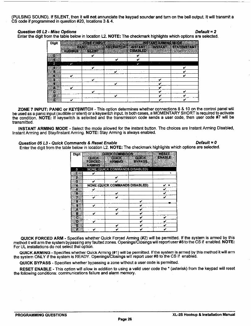
Quaetiorr 05 L2 - Mist Options Dafsu\t = 2Enter the digit from the table below in Iomtion L2. NOTE: The chackmak highhghts wNch options are selected.
ZONE 7 INPUT PANIC or KEYSWITCH - This option determines whether mnnections 8 & 10 on the control panel willbe used as a panic input (audible or silent) or a keyswitch input. In both cases, a MOMENTARY SHORT is required to activatethe condition. NOTE: If keyswitch is selected and the transmission mde sends a user code, then user code #7 will betransmitted.
INSTANT ARMING MODE - Select the mode allowed for the instant button. The choices are Instant Arming Disabled,Instant Arming and Stay/Instant Arming. NOTE: Stay Arming is always enabled.
Quastion 05 L3 - Quick Commands & Rasat Enable Default = OEnter the dioit from the table below in Ioation L2. NOTE: The checkmark highlights which options are seleded.
QUICK FORCED ARM - Specifies whether Quick For@d Arming (#2) will be permitted. If the system is armed by thismethod itwill arm the system bypasaing any faulted zones. Openings/Closings will report user#8 to the CS if enabled. NOTE:For UL installations do not select thsi option.
QUICK ARMING - Specifies whether Quick Arming (#1 ) will be pemitied. If the system is armed by this method it will armthe system ONLY if the system is READY. OpeningtiClosings will report user W to the CS if enabled.
QUICK BYPASS - Specifies whether bypassing a zone without a user mde is permitted.
RESET ENABLE - This option will allow in addition to using a vahd user code the ● (asterisk) from the keypad will resetthe following conditions communisetions failure and alarm memory.
PROGRAMMING QUESTIONS XL-2S Hookup& Inahllation ManualPage 26

Que5ti0fl 05,64- Rest. Fo!l. Lot>p, User On-1ine,CS TeatK.P. Ringback & User 5 Asrn Defaulit = OEnter the digit from the table below in location L4. NOTE: The checkmark highlights which options are sek?cted.
RESTORE AFTER BELL - Restores will be transmitted after the loop has returned to normal after bell cutoff, or uponsystem disarming regardless of the loop status.
RESTORE FOLLOWS LOOP - This option will transmit restores immediately upon zone restoral while the system is armed,or upon system disSrm regardless of the loop status.
USER ON-LINE & CHIME TOGGLE ENABLEO - This option indi~tes whether the end user command (#9) for the on..linedownload will be enabled, This command would allow an end user to be instructed how to initiate an on-hne download andpossibly prevent a semice CSII.This also controls the user chime toggle enable. If enabled, then the user will be able to to!~glethe system chime.
CS TEST RING BACK - Normally, after a CS Test Report has reached the Central Station, a sounder ringback Carl beheard from the keypad indicatin a successful communication to the CS. If SILENT is selected, then NO sounder ringbsck
8will be heard from the keypad a era CS Test Report. If AUDIBLE is selected, then s sounder ringback will be heard fromthe keypad after a CS Test Repofl.
USER 5 ARMS ONLY - If selected, then user 5 will be used as an ARM only code (Maid Code); it will not disarm thesystem.
QUESTION 06 SYSTEMTIMIEOUTSThere are 4 locations (L1-L4) wkhin this question which define various system timing options as follows:
Question 06 Lf - Entry Delay 1 Default = 6Enter the desired ent~ delay time. Refer to ExitiEntry Times below for valid choices, If zones 1-3 are delay zones, tlhen
they follow entry delay 1. For UL applimtions the maximum entrance delay shall not exceed 45 seconds lor household~~~~y~s or 15 seconds for commercial burglay applications. NOTE: See programming question #07, location 4 for Entry
XL-25 Hookup & Inatsilation Manual PROGMMMING QUESTIC~Page 27

Question 0662- Exit Delay Default = 6Enter the desired exit time. NOTE: For UL applications the maximum exit delay shall not exceed 60 seconds,
Quastion 06 L3 - Burglary Ball Cutoff Default = 5Enter the desired bell cutoff time on alarm conditions for burglary and panic in 3 minute intervals. The vatid range of input
is 1- F, with F indicating an infinite burg bell cutoff. Example 3 = 9 minutes. For UL installations in commercial apphcationsthe minimum bell cutoff shall be 15 minutes. or 6 minutes for household bur~law aDD~cstions..
Quastion 06 L4 - Firs Ball Cutoff Dafault = FEnter the desired bell cutoff time for fire conditions in three minute intervals. The valid range of input is 1- F, with F indi~ting
an infinite fire bell cutoff. Example 3 = 9 minutes. For UL installations the minimum fire bell cutoff time shall be 6 minutes.
QUESTION 07 MISCELWNEOUS SYSTEM OPTIONSThere are 4 Iosations (L1-L4) within this question which define various system timing options as follows
Question 07 L1 - Entw Delay 2 Default = 2Enter the desired entry delay time Refer to ExiffEnt~ Times in question #06 for valid choices. If zones 44 are delay
zones, then they follow entry delay 2. For UL applications the maximum entrance delay shall not exceed 45 seconds forhousehold apptimtions or 15 semnds for commercial burglary applications. NOTE: See programming question #06, lo@tion1 for table of apphcsble values. !F ZONE 6 IS PROGRAMMED AS A FIRE ZONE FOR BELL SUPERVISION, THEN TO USEEXIT DELAY 2 SELECT EITHER ZONE 4 OR 5 AS A DELAY ZONE.
PROGWMMING QUESTIONS XL-2S Hookup& Installation ManualPage 2S

Question 07, L2 - Remote Communications Ring Count Default = C
Enter‘the digit from the table below in Iocstion L2. Select from the choices below
REMOTE COMMUNICATIONS f?lNG COUNT - is a the number of rings for the control panel to pickul) for a remotecommuni~tions session. Ttis should be selected to a value that does not interfere w,ith normal operation of the panellocstion.The default value is 12 tings, NOTE: A value of O means that remote programming will be disabled,
Question 07, L2 - CS Test Time lntewa\s and European Ring Detect DefauAf= 1
CS TEST TIME INTERVAL -if enabled, the system will transmit the test mde to the Central Station at the inlewal selectedin the absence of any other signal, Select from daily (24 hour), weekly, 27 days, 60 daya or 90 days. Trsnsrnission of anysignal will reset the CS Test clock. For example, if a business opened and closed 6 days a week, then a teslt signal will begenerated at the intewal selected afl,er the last closing signal, Enter the CS Code in question #18, lo~tion :1, NOTE Thismust be selected for UL installations,
EUROP~N RING DETECT- Use this option if a European Telephone System is used only. This option changes the tingdetection frequency used for automatic answer mode for remote (Downloading) purposes only a~ording to the?programmedring wunt (see programming questicln W7, location 2), If selected, the ring detection frequency range is 10- 90 Hz. If notselected, the frequency range is 16- 90 Hz.
XL-2S Heokup & Installation ~nual——
PROGRAMMINIG QUESmIDNSPage 29

Questjon 07, M - Smoke Power or Ttigger Types Defasdt = OThe smoke power terminals (15 & 16) mn be used as a trigger output. If a fire zone is used in the eyatem, the trigger
should be programmed as “O. If the fire devim does not need a power reset, or no fire zone type is selected, the trigger mnbe programmed as follows
TWO WAY VOICE - Ttis trigger will activate when tine sekure occurs if the event is any of the following: burgla~, fire,duress, keypad panic, keypad fire or keypad auxifla~. It will not activate for CS test, openings/closing, trouble, bypass, cancelor restore. It will deactivate about 1 second before disconnecting the telephone hne. Also, at the time of release, keypadsounders will be silenced for the remaining duration of the bell output cycle. The bell will time~ut or a valid user code willterminate.
NOTE: Unlese otherwiee specified, the trigger output is nornsslly flosthsg end actively sinks on activation.[
QUESTION 08 ACCOUNT NUMBER 1Enter the three(3) or four(4) digit subscriber account number for Central Station phone number 1 in locations LI-L4. If a
three(3) digit number is used then enter an A in location L4. Vafld entries are O-9, and B-F. The value A is interpreted as thenull value for account numbers.
QUESTION 09 ACCOUNT NUMBER 2Enter the three(3) or four(4) digit subscriber account number for Central Station phone number 2 in lo~tions LI-L4. If a
three(3) digit number is used then enter an A in location L4. Valid entries are O-9, and B-F. The value A is interpreted as thenull value for account numbers. If the second phone number is not used this question ~n be Iaft as factory defaulted.
THIS ACCOUNT NUMBER MUST BE ENTERED IF YOU HAVE PROGRAMMED ASECOND RECEIVER PHONENUMBERFORBACKUP ORSPLITREPORTING.
PROGRAMMING QUESTIONS XL.2S Hookup& Insmllation ManualPage 30

10.1, ZONE PROGMMMIINGQuestions 10-15 represent all the options related to programmable zones 14. Each question mntains foulr(4) lo~tions
LI-L4. The first two locations (L1 & L2) define the zone tyge and options, The second two Iomtions (L3 & L4) define the alarmcode irsnsmitted to the Central Statioh for that zone, -”
ZONE TYPES
Zones 14 ~n be programmed for any one of the following zone &pes
BURGLARY (CONTROLLED) ZONE:
N(3TE: For 24Hour Zone tvpssee next pga.
DELAY - This is the indust~ standard exi~ent~ zone. When the system is armed exit time begins. After exit,expires, onysubsequent violation ofthiszona will begin ent~time. Ifthesystem is not disarmed within the programmed {?nt~ time analarm will occur. Thekeypad sounder will annunciate steadily dufingentV time! unless there had been an alarm condition,atwhichtime itwill pulse. Delay zones will activate instantly whanthe system ls armed using the STAY/lNSIANT mode ifenabled. Delay zones employ the Exit Error Warning feature described inthe note below.
INTERIOR - All interior zones have exit delay time upon system arming, Furthermore, all interior zones will have entrydelay time ifadelay zone isviolatediirst. Ifthiszone isviolated first however, itwillgenerata animmediate alarm. interiorzones are bypassed if the system ia armed in the STAY MODE. interior zones emp!oy the Exit Error Warning feat~jre describedin the note below,
PERIMETER - This zone type (sometimes known as INSTANT) will generate an alarm when violated while ithesystem isarmed.
E_EXIT ERROR WARNING -At the ond of exit timea 1 second window is atsrted. If any delay orinb?riorz ones
T
are violated after arming within this window (exit time expires and entry tima stsrte) the burgla19 bell a!~dkeypad sounder will be turned om forcing the user toenter their code preventing a falae alsmtranamission.TMe helpe avoid tha common falee alarnsa that take placa afler arming the system.
BURGMRY ZONE OPTIONS
RESTORE - This option is selected for all burgla~ zones by enabling the restore repofi mde (question #1 !3, location 2)and enabling zone restores in question #04, lo=tion4.The programmed restore code will be reported upon bell cutoff,assuming the loop is restored unless F!estore Follows Loop is selected in question #05, Iowtion 4. The restore code will alaobe reported if the system is disermed (~uring an alarm. NOTE: Restore is not selectable by zone.
BYPASS IN STAY - This option allows zones to be bypassed when the system ie armed in the STAY mode!.
CHIME - If this option is selected the keypad sounder will annunciate for 1 aemnd when this zone isviolated in ‘thedisarmedmode.
XL-25 Hookup & Installation Manual——
PROGRAMMING QUESTIONSPsge 31

DIALER DELAY - If this option is selected, then the system will allow a 15 second delay before diahng, allowing the enduserto ABORT thetrsnsmission. Ifthisoption is not selected, anyalarm rendition will result inan immediate transmissionthat cannot be aborted. NOTE: For UL inshllations dialer delay may not be used.
DAY FEATURE - If a zone with this option is violated while the system is DISARMED, the keypad sounder and zone LEDwill pulse for as long as the violation remains. In addition, the SYSTEM TROUBLE CODE will be transmitted to the centralstation. THE SOUNDER CAN BE SILENCED through entry operation of any vatid user code. ~ile the system is armed, aDAY zone will act aa an alarm when violated.
Zones 1% can be progr
24 HR. ZONES
‘E zones on the system contain Fire Verification Logic. Upon detection of the first violation, smoke detectorpower will be reset for a period of 8 seconds. After this time period: power is restored. For a period of 5 semnds the fire zonewill not be scanned allowing the smoke detectors to settle. Future violations within a two minute period will result in a PULSINGBELL OUTPUT, RAPID PULSING ZONE LED,and IMMEDIATE transmission to the CS. Fire signals cannot be aborted.
Entry of any valid user code will silence the sounder, bell and reset smoke detector power. If the system detects that thefire zone is still violated within 2 minutes of power reset, the zone LED will pulse slowly to indicate a fire trouble. Thereafter,smoke detector power will be reset every 4 minutes automatically in an attempt to clear the fire zone.
In the event the fire zone experiences an open, the systam indicates fire trouble by pulsing the keypad zone LED andsounder slowly. The system troubla code ( followed by the zone code ) will be reported to the CS.
The keypad sounder can be SILENCED through entry of ANY VALID USER CODE. NOTE: FIRE ZONES cannot bebypassed.
24 HR. ALARM - Ttis zone type is always active, independent of the system arming status. Programming options includeaudible (STEADY BELL) or silent (NO BELL or keypad indications). Upon violation the zone LEDS will pulse rapidly (audiblezones only) and an immediate CS transmission will occur which cannot be aborted.
24 Hour Alarm zones =n be bypassed, however they cannot be unbypassed if a violation exists on the zone terminals.
24 HR. TROUBLE - This zone type is shays active, independent of the system arming status. Programming optionsinclude audible (PULSING KEYPAD SOUNDER) or silent. Upon violation the zone LED will pulse slowly. Trouble conditionmust exist for 15 seconds before a transmission will occur. The keypad display and sounder will clear upon zone restoral.
24 Hour Trouble zones =n be bypassed, however they mnnot be unbypassed if a violation exists on the zone terminals.
NOTE: 24 hour trouble is not to be used for fire and burglay detection zones. 24 Hour silent alarm zones are not to beused for petimeter protetiion. THE SOUNDER MAY BE SILENCED THROUGH ENTRY OF ANY VALID USER CODE.NOTE: IF ZONE 8 IS PROGRAMMEDASA FIRE ZONE FOR BELL SUPERVISION, THEN TO USE EXIT DELAY2 SELECTEITHER ZONE 4 OR 5 AS A DELAY ZONE.
PROGRAMMING QUESTIONS XL-2S Hookup& Installation ManualPage 32

ZONE AWRM CODES
As previously specified locations L3 and L4 of the zone questions represent the alarm mde that will be reported to thecentral station.
NOTE: Zones will trsnsmit to the Cerrtml Station unless these digits sre defined ss AA for any individual zome,or the local tialer option is select(?dfor sII zones in question W4, location 1.
T
Based on the dialer format selected enter the alarm code ss follows
STANDARD FORWT(3Xtor.4Xi :Enterthe desired single digit alamcode inlo~tion L3fortt}e specific!zone. Thevalue placed lnlL4willno be used.
EXTENDED (3X! Eti or 4X1 Ext.): Enter the ‘desired first digit of the alarm mde in location L3 for thespecific zone and the second digit In L4.PARTIAL EXTENDED {3X1 Part. Efi. or 4X1 Pe@. Ext.) Enter the desired digit in both Iomtions L3 and L4forthes ecificzone. Thlswill generate asingledi lttmnsmissions fo~alarms andtroubles (thesecond digit
[ ?will not eu3ed)and an(sdendedt ran$mi~slons orallsystem condlbonssuchasrestoresrb ypasses,openings/clos~ngs, etc. (the second digit WIII be used).3X2pr4x2: Enter the~esiredfirstdi itofthe alamwde inlo@tion L3andthe second digit in L4forthe
Jspeclficzone. Both digits w!ll be use foralltrsnsmissions.
NOTE: Formore information on C!SRepoting Formste refer to Appendix Aattheback ofthismanuiil.=1
QUESTIONS40-15 ZONES 1-6
There are 4 Iocstions (L1 -L4) within each of these questions which define the operation of the zones. Enter a 2 digit numberin locations L1 and L2 from the zone c!lart for the desired type for this zone. Enter the desired alarm code in locations L3 :IndL4 for this zone relative to the dialer format selected.
QUESTION 10 ZONE 1 WPE & CS CODE m~Question 10, Lf & L2 - Zone f Type Oefeu/t,= 20
Question 10, L3 & L4 - CS Code for Zone 1 Default:= 31Zone 1 = Delay (Entry/Exit) w/CS reporting ade = 31
QUESTION f 1 ZONE 2 ~PE & CS CODEQuestion 1!, LI & L2 - Zons 2 Type
Question 11, L3 & L4 - CS Code for Zone 2Zone 2 = Interior Follower w/CS repoting code = 32
QUESTION 12 ZONE 3 ~PE & CS CODEQuestion 12, L1 & L2 - Zone 3 Type
Question 12, 63& L4 - CS Code for Zone 3Zone 3 = Instant (Perimeter) w/CS repoting code= 33
QUESTION 13 ZONE 4 ~PE & CS CODEQuestion f3, L1 & L2 - Zone 4 Type
Question 13, L3 & L4. CS Code for Zone 4Zone 4 = Instant (Perimeter) w/CS reporting code= 34
QUESTION 14 ZONE 5 WPE & CS CODEQuestion 14, LI 6 L2 - Zone 5 TMpe
Question 14, L3 & L4 - CS Code Ibr Zone 5Zone 2 = Instant (Perimeter) w/CS reporting wde = 35
Defsult:= 41
Default:= 32
m~Defeult:= 10
Default:= 33
m~Default:= 10
Default:= 34
-~Defeult:= 70
Dafeult:: 35
~.2S Hookup& InsWllation Manual——
PROGRAMMING QUESTIONSPage 33

QUESTION15 ZONE 6 TYPE & CS CODEThere are 4 locations LI -L4 in ttis question as follows
Question 15, LI & L2 - Zone 6 Type Default =10
Question 15, L3 & L4 - CS Code for Zone 6 Default ❑ 36Zone 6 = Inatent (Perimeter) w/CS reporting code= 36
-3 are programmed as DELAY zones, they follow ENTRY DELAY 1. If zones 4 -6 areprogrammed as DEWY zones, they follow ENTRY DELAY 2.
QUESTION16 CS CODES for AMBUSHand AC LOSSThere are 4 locations LI -L4 in this question aa follows
Question 16, L1 & L2 - Ambush Code Default = AAIf an ambush code is defined, then user number6 is the ambush code. The same rules apply here regarding dialer format,
If transmission is not desired, then program AA in Iocetions LI & L2. NOTE AMBUSH transmissions are immediate and notabortable.
Question 16, L3 & L4 - AC Loss Code Default = AAThe same rules apply here regarding dialer format, If transmission is not desired, then program M in locations LI & L2.
NOTE: AC LOSS is reported 15 minutes after detection,
QUESTION 17 CS CODES for PANIC and LOW BATTERYThere are 4 locations L1-L4 in this question.
Question 17, L1 & L2 - Panic Code Default =22The same rules for programming regarding dialer format apply here. If transmiaaiona ara not desired, then program M in
Iocafiona 1 &2. NOTE: PANIC transmissions are immediate and not abortable.
Question 17, L3 & L4 - Low Battary Code Default = AAThe same rules for programming regarding dialer format apply here. If transmissions are not desired, then program AA in
locations 1 &2. LOW BA~ERY transmissions will be reported 4 minutes after detection. LOW BATTERY RESTORE CODEwill be repotied WITHIN 4 minutes after detection of GOOD BA~ERY condition,
QUESTION 18 CS CODES for OPEN/CLOSE and CS TESTThere are 4 locations LI -L4 in this question,
Question 18, L1 - Opening Code Default = A
Question 18, L2 - Cluing Code Default = AL1 is the single digit OPENING CODE. L2 is the single digit CLOSING CODE. Enty of AA into these two locations means
that openings and closings are not desired. If a dialer format other than standard is programmed then the second digittransmitted will be the user number,
Question 16, L3 & L4 - CS Test Coda Default = AAL3 - L4 is the CS Test CODE, If CS Test code is selected then ANY vahd transmission will reset the CS Test timer.
NOTE: Any digit entered will be transmitted unless CS Test is diseblad; to disable see question #07, location 2.
QUESTION 19 CS CODES for BYPASS, RESTORE, TROUBLE and CANCEL ~There are four(4) locations LI - L4 in this question.
Question 19, L1 - 5ypsa Code Dafault = ALI is the single digit system BYPASS CODE that will be repotied to the central station if a zone is bypassed, UPON
ARMING. Entry of an A msans that bypasses are not transmitted. If a two digit diahng format has been seleded then theBypass code will be followed by the progrsmmad second digit of the zones code.
Question 19, L2 - Restore Coda Default = AL2 is the single digit system RESTORE CODE reported to the central station. Restores will be reported for all burglary or
24 hour zones by enabfing this mde (digits O-9, B-F) and enabfing zone restores in quastion #04, location 3. Entry of an Ameans that restores are not transmitted. If a two digit dialer format has been programmed then the restore mde will be followedby the programmed second digit of the zones code. NOTE: Restore is not selactsble by zone.
Question 19, L3 - Trouble Code Default = FL3 is the single digit system TROUBLE CODE reported to tk central station. This code will be reported on DAY TROUBLE
and any FIRE TROUBLE. If a two digit format has been programmed then this code will be followed by the semnd digit ofMe respective zones code.
PROGRAMMING QUESTIONS XL-25 Hookup & Ins@llstion ManualPage 34

Question 19, U- Cancel Code DefauN.= 8L4 is the single digit system CANCEL CODE reported to the mntrsl station. TMs code will be sent if after a violation of a
controlled zone, a user code is entersdl. If the zone is still violated, enby of a user code will transmit the csncai de. If thezone is programmed for restorel, then the restore code will be transmitted when the loop status has returned tc, normal. Anentry of A in this field in~cates that canml codes are not transmitted. In @rmats requiring 2 digits, the user numbler ~nctionsas the second digit.
QUESTION20 CS CODESfor KEYPADFIREand KEYPADAUXILIARY --.~hers are 4 locations LI-L4 in this aluestion,
Question 20, 61& L2 - Key~d Fin Code Defsult ❑ AA1.1- L2 is the alarm code that will b<!transmitted upon activation of the keypad fire condition (pressing the 7 & 9 keys on
the keypad), This code can vary from any of the zones which are programmed as fire.
Question 20, L3 & L4 - Keypsd Auxiliary Ctia Dafau/f = AA1-3- L4 is the code transmitted to th{eCS for keypad aux. condition ( 1 & 3 from the keyped).
NOTE: These keypad emergency conditions are optional and can be enabled within question #05 of the programmirlgsequence. If either or both of these transmissions are not desired, program their respective Io-tions W.
QUESTION 00 INSTALLER C~DDEThere are 4 locations LI - L4 in this question. Enter any 4 digit (0-9 installer code desired). This code is used to ENTER
the system programming mode via the keypad.
Typically each installing company would usa a unique inetaller code in order to prevent unauthorized peoplefrom gaining accees to their panels.
T
XL-2S Hookup& Installation Manual——
PROGWMMING QUESm~4SPage 35

~ 1. DATA ENTRY VIA LED& LCD BASED KEYPADS
TMs se~on describes the physi~l keystrokes necessary to perform keypad programming and how to interpret the datedisplayed on the LED based keypads (XL4600RM, XL4600SM or 6615) snd on the LCD keypsd (6605) during programmingoperations. NOTE: A~ual keypad programming should be performed after ampletion of the programming sheet.
qI.I. HOW TO ENTER PROGRAMMING MODEVIA EITHER LED OR LCDKEYPADS
The SYSTEM programming mode @n be entered WILE DISARMED ONLY ss tillows
where TO ENTER INSTALLER PROGMMMING: [CODE] ~]~NSTALLER][l]
[COD~ Press the CODE bution
r] Press the asterisk ~) button
[INSTALLER] Entar the 4 DIGIT INSTALLER CODE (default= 2466)
[1] Press “$” button. This indi~tes Installer Mode 1.
41.2. WHAT YOU SEE ON THE LED KEYPADPROGRAM MODE = READY LED:
Upon entering the installer keypad programming mode the READY LED will slowly pulse, and will mntinue to pulse untilleaving this mode. The remaining LEDS display the question number and lo~tion wntents as indimted below:
E@
/+’ ‘ :~~ ;3::yQUESTION NUMBER +4 3 ● 1W
y; : “’
06 . Rdy SLOWLY PULSING
*7
08
@
v L
XL4600RM KEYPAD
+~?),SLOWLY PUKING
\f\ I /
1 sYstem
LOCATIONCONTENTS +
[DATA)
~+6615 KEYPAD
XL4600SM KEYPAD
TNOTE The LED keypads DO NOT display ma
cumti Iwtion (Psmon win tie question),
Thw display onw tie c.mnt I=ation continm
(da values). You must k-p ~ck d me
l~on Mi” me qu=tion or else sam tim
me Winning and mve to me dw!ti p~on
using me # b-n. tiever, me LCD kwpads
dl’olay me cu~nt Itio” (s- neti wge), I
DATA ENTRY W LED& LCD BASED KEYPADS XL-2S Hookup& Inetsllation ManualPage 3S

QUESTION NUMBERS = ZONE LED$ There are 21 (00-20) total questions, with multiple data ent~ lo~tions.
Zone LEDS 1 through 5 display the current QUESTION NUMBER (not the specific Iomtion within each question) as follows
In the diagram shown on the following page, the question number is the total you get when you ADD the values of allLEDS that are ON.
EMMPLES:Zone 1 ON, Zones 2-5 OFF = QUESTION 01Zone 1 ON, Zone 2 ON, Zones 3-5 OFF = QUEST!ON 03Zone 2 ON, Zone 3 ON, Zone 4 ON, Zones 1 and 5 OFF = QUESTION 14
LOCATION CONTENTS = SYSTEM STATUS LEDS
The remaining status LEDS (ARM, STAY,lNSTANT,AC/LB) display the DATA that resides in EACH Ioetion within thecurrent question. Asperthe diagram which follows andexplanation above, thevalue located next to each LED must beADDED to calculate the total data, for each location.
EXAMPLESArm ON, Stay,lnstant,,and AC/LB OFF = 1Arm ON, Stay ON, Instant and AC/LB OFF = 3
The following chart tisplays binay values that you will see on these LEDS for the letters A-F which may I)e entered insome locations of the program sheet.
A 10 Stay & AC/LB= ONB 11 Arm, Stay, & ACILB = ON
c 12 Instant, & AC/LB= OND 13 Arrn,lnatent, & AC/LB= ONE 14 Stay,lnatsnt, & AC/LB = ONF 15 Arm, Stay,lnstant, & AC/LB= ON
tI.3. WHAT YOU SEE OFdTHE LCD KEYPADUpon entering the installer keypad programming following display will appear
i !
The display shows the current queetion number (QUES), tha location within the question (L) and the current value withinthat location (DATA =). This corresponds to the programming worksheet.
11.4. HOW TO ENTER DJ4TATMs section of the manual describ[ss the physical keystrokes to enter the data written on the program sheet.
MOVEMENT BETWEEN QUESTIONS System program mode starts with question 1 displayed. RANDOE1 JUMPS TOANY QUESTION CAN BE MADE BY PRESSING THE* (ASTERI!3K) BU~ONAND THE 2 DIGIT QUESTION NUMBER.
Questions mn be accessed randomly or sequentially
Example: Jump to question 07= Press•07
MOVEMENT WITHIN QUESTIONS
The proper question number will be displayed by the zone LEDS and the otherstatus LEDS will display the contents of the FIRST Io=tion in that question.
The zone LEDS display the question number and the other status ILEDSdisplaythe contents (data) within each lo~tion. MOVEMENT FROM LOCATION LITO THE NEXT LOCATION WTHIN ANY QUESTION CAN BE PERFORMEDBY PRESSING THE # (POUND) BUTTON.
The other status LEDS will display the contents of each Iomtion as this bultonis prasaed.
DATA ENTRY To alter the value in any location , enter the desired DIGIT fromlthe programsheet, and press the # button.
=
NOTE: THE # BUTTONHBE PRESSED AFTER THE ENTRY OF the DESIRED DIGIT. THE SY!STEM WILL
7
NOT PROGRAM THE DIGIT UNTIL THE POUNO (#) BUTTON IS PRESSED, THEREFORE IF A MISTAKE IS MDE
=.-2S Hookup& Installation Manual——
DATA ENTRY MA LED& LCD BASED KEYPJiDSPaga 37

Numeric entriee O-9 can bs ~rformed by Pressing the respective keypadbutton. Entries of A-F require 2 keystrokes as followe:
Preasthe CODE butionfollowed by14forvalues A-F.
VALUE KEYSTROKES VALUE KEYSTROKESA CODE 1 D CODE 4B CODE 2 E CODE 5c CODE 3 F CODE 6
Example Enter an A = Prsss CODE followed by 1.
EXIT SYSTEM PROGRAM MODE After all programming has been mmpleted, PRESS THE STAY BU~ON TOEXIT THE SYSTEM PROGRAM MODE. All the LEDS will turn ON forapproximately 10 sewnds, before the system returns to normal daily operation.
QUESTIONACKNOWLEDGMENT The keypad will heap between keystrokes. In addition, a beep will be generatedmnfirming advancement between questions numbers.
Four beeps will be generated if an invatid input is entered. Upon entry of invalidinput you are positioned at the same question number and lo~tion as prior tothe input error.
SUMMARYOFSYSTEM PROGRAMMING
DATA ENTRY VIA LED & LCD BASED KEYPADS XL-2S Hookup& Ins@llation WnualPage 38

II .5. ZONE DESCRIPTOR?PROGWMMINGThe LCD based keypads have the f%patitity to display 12 character zone descriptors which can be programmed directly
through the keypad. These descriptors are entered as programming questions 21-26.
NOTE: These questions can only be accessed by an LCD keypad, or the EZ-Mate Programming Devices.
The zone descriptor questions are i]s follows
QIJESTION21 ZONE 1 DESCRIPTOR -~
QUESTION 22 ZONE 2 DESCRIPTOR -~
QUESTION 23 ZONE 3 DESCRIPTOR --
QUESTION 24 ZONE 4 DESCRIPTOR --
QUESTION 25 ZONE 5 DESCRIPTOR m~
QUESTION 26 ZONE 6 DESCRIPTOR --
Example: To program the descriptor for zone 3 enter ● 23, to access question 23.
Men programming the English zone descriptors the following techniques are used to program the characters
Inse@ a SPACE and advances the tumor.
[cool=] Moves the tumor to tb LEFT one spaa.
[lNSTAIN~ MOVSSwe cumorto Me RIGHToneswce.
m iINCREMENTS the charsster one at a time at the cursor.
Er] PI Scrolls fomrd (UP) through the charscter set NOTE
Pressing any key WII stop the scroll.
[9] DECREMENTSme Chammr one at a time at the tumor.
[w [91 Scrolls hc~rd (OOWN) through the chrscter set.NOTE P-sing any key till stop the scroll
NOTE: The characters available through the LCD based keypads are as follows:
!''#$%&(~+-./Ol 23456789 ;=@BCDEFGHlJKLMNOPQRSTUMYZ
E NOTE: The Zone Descriptors are not defaulted when a system default ie performed. z]
~.2S Hookup& Installation Manual DATA ENTRY WA LED& LCD BASED KEYPADSPage 39

~ ~. SYSTEM DEFAULTS
The system is stipped from the facto~ programmed with default values These values have been selected to meet therequirements of a mmmon installation and may suit your needs.
To reload the factory default valuea, remove all power from the system (AC & DC). Next shoti JPI to JP2, Wthshoti etill intact reapply power (AC then DC), wait 5 s=onds then remove ehort with the power etill apptied.The installer can also do a System Default or User Code Defiult through Inetsller Mode 1 (refer to the InstallerModes section of this manual). The Zone Descriptors will NOT return to their default valuee.
NOTE: A programming option exists within the EZ- Mate PC Downloader devices known as DEFAULT LOCKOUT. If thisoption is selected then a system default will not overwrite the CSID or installer mde potion of the program. Ttis will preventan installer other than the original installer from takng over an acmunt without moperstion,
1 1234 ! Mas@r User2 NUL! Iomal User3 NUL4
.Ioml user
s NULL I Am Onti6 NULL~
SYSTEM DEFAULTS XL-25 Hookup & Installation WnualPage ~

13. SUMMARY OF KE7fPADFUNCTIONS
13.1.
13.2.
IUSER FUNCTIONS
ARMING~/SARMING:
STAYARMING:
STAYANSTANTARMING:
BYPASS:
QUICK BYPASS:
USER CODE PROG~MMING:
USER CODE DELETION:
QUICK ARMING:
QUICK FORCE ARMING:
TOGGLE CHIME:
ON-LINE DOWNLOADING:
PANIC:
FIRE:
AUX/L/ARY:
AMBUSH:
INSTALLER MODES
KEYPAD PROGRAMMING:
SYSTEM LOG VIEW:
UNATTENDED 00 WNLOAD:
ON-LINE DOWNLOAD:
SYSTEM DEFAULT:
USER CODE DEFAULT:
[Enter any valid four digit user code]
[STA~ [Enter any vatid four digit user code]
[STAW [lNSTAN~ [Enter any vatid four digit user code]
[BYPASS] [Enter sny vakd four digit user code] [Zmre ~
[BYPASS] [Zone ~
[CODE] [Enter master user cede] [user fl [Enter 4 tigit user codel
[CODE] [Enter master user code] [user fl r]
[M [11
[w [21
[w [61
[m [91
r]& [mat the same time
~ & [9] at the same time
[1] & [3] st the came time
[Enter user code 6]
[CODE] ~] [Enter insblier code] [1]
[CODE] r] [Enter installer code] [2]
[CODE] ~ [Enter installer code] [3]
[CODE] fl [Enter installer code] [4]
[CODE] [~ [Enter instcller code] [1]then preee [1] & [3] at the same time
[CODE] ~ [Enter installer code] [1]then preae m & [9] at the same tima
NOTE: All these functions Mn be petiormed from all keypad types (XL4600RM, XL4600SM, 6615 or 6805).
~.2S Hookup& Installation Manual——
SUMMARY OF KEYPADI FUNCmONSPage 41

~4.APPENDIX A - CENTRAL STATION REPORTING FORMATS
Ttis security system is designed to transmit data to a Central Station Re~iver when an Alarm, System Trouble, or anOpening/Closing omurrs. Due to the many different types of CS receivers in the market, this system can transmit data invarioua formats. Each instslting mmpany determines which format best suits its needs based on many factors. Of these, theCS receiver type ia a major factor.
In transmitting data to the CS receiver, the first avent that o=urrs is that the system’s digibl communicator will aeiza thehome phone hnes. Then, it will dial the CS#l telephone number (programming question #01). men the CS re=iver picksup the ringing phone line, it will transmit a “Handshake” frequency (either 1400Hz, 2300Hz or HiLo) back to the digitalcommun~tor, After receiving the “Handshake” frequency, the digital communicator will transmit the data in the fO~atprogrammed in question #04, Iomtions 1, 2 & 3 (either in Pulse or DTMF). Assuming the CS recaivar verifies the datatransmission as valid (after 2 succasful rounds of data or 1 vahd parity round), it will transmit a “Kssoff frequency back tothe digital communicator. This causes the communicator to stop transmitting, unless more data is available, in which caseadditional date transmissions and “Mssoffs” will occurr. After the final “NssoW, the CS receiver will release the phone fineand process the data to its display and associated peripherals. (computer and printer). If for any reason the the digitalcommunimtor, does not receive the “Nssoff, it will proceed to dial the CSW telephone number or dial again the CW1telephone number Of CW2 is not used). It will continua to dial (8 times for each CS talephone number programmed) until a“Kssoff is received. If after dialing 8 times for each CS Telephone number programmed a “Hssoff is not received: the systemwill display “Communication Failure” at the keypad. This message is cleared after the neX succsasful transmission or by theuser at the keypad.
The following iss general description of the various formats transmitted by this system.
?4.f. STANDARD (3X1 Or 4X1)
The Standard Repotiing Fornrat: AAA E or AAAA Ewhere
AAAA = Three or Four digit Acmunt Number (PROG. QUESTS. #08& 09)
E = Single digit Event code it is the first of the 2 programmable reporting code digitsStandard format is transmitted in Pulse and involves a 3 or 4 digit account number followed by a single digit event rode.
It can be transmitted with parity (1 round of data) or without parity (2 rounds of data). A disadvantage of this format is that itcan onlv transmit a total of 15 evant codes (O -9, B - F) without indentitiing zonaa or usars. Examples:
3X1 W/O PARIW1233 (Ist round)
1233 (2nd round)
1233 (resulting data)
4X1 WIO PARIN
12343 (Ist round)
12343 (2nd round)
12343 (resulting data)
3xI WIPARIW -
12336 (single round)
1233 (resulting data)
4X1 WIPARIN
123432 (single round)
12343 (resulting data)
NOTE: Parity ia a number darived automatically by the dialer utilizing a mathematical formula (modulo 15). Ex:1233 adds up to 9. This ia subtracted from the next Wgheat multipla of 15; in this caee, 15-9 ❑ 6. If the CSreceiver accapts a va~d parity digit, it considers the data tranamieeion valid, delivers a “Waaoff andprocesses the data. The parity digit is not displayed. Its only purpose ia for validation of data transmitted. It isnot a programmable dlgi~ it is generated automatically by ths dialer when the parity option ia selected inprogramming question #04, location 2. Tha obvious advantage of using parity ia speed. The transmission timebetween daler and receiver is shorter because fewer digits are transmitted with it as oppoead to without it.
APPENDIX A - CENTRAL STATION REPORTING FORMATS XL-2S Hookup& Installation MsnualPage 42

14.2. EXTENDED (3X1 EXT. or 4X1 EXT.)
The Extended Repati/ng Fomat: AAA ~ or W EZwhere
AMA = Thraf? or Four dgit Account Number (PROG. QUESTS. #08 & 09)
E = Single digit Event code it is the first of the 2 programmable reporting code digitsZ = Zone or User identifiefi it is the second of the 2 programmable repofing code digit$
I:tiended fo~at is transmitted in Pulse and involves a 3 or 4 digit account number followed by a double ti9it rePofif19code.The only purpose for using the E)dended format (sometimes known as Universal or Expanded format) is to be able totrensmit more than 15 codes to the CS receiver. It does this by efiending the event code from the previous round of dataresulting in a 2 digit reporting code. It can be transmitted with parity (2 rounds of data) or without parity (4 rourlds of dats).There are 15 possible event codes, each of which can have 15 different zone or user identifiers. As a result, a total of 225intifidual events can be reported. Examples
3X1 Ext. WIO PARIW 3X$ Efi W/PARIW1233 (Ist round) 1233 (2nd roud) 12336 (lst round)
3331 (3rd round) 3331 (4th round) 33315 (2nd round)12331 (resulting date) Burgla~ Zone 1 12331 (resulting data) Burglay Zone 1
4X1 Ext. WIO PARI~ 4X1 Ext. W/PARl~12343 (Ist round) 12343 (2nd round) 123432 (Ist round)33331 (3rd round) 33331 (4th round) 333312 (2nd round)123431 (resulting data) Burgla~ Zone 1 123431 (resulting data) BurgiaV Zone 1
14.3. PARTIAL EXTENDEID (3X1 PART. EXT. or 4X$ PART. EXT.)
The Partial Extended Reporting Fomat: AAA EZ or AAAA EZwhere
AAAA = Thref? or Four digit Acmunt Number (PROG. QUESTS. #08 & 09)E = Single tigit Event code; it is the first of the 2 programmable reporting code digitsZ = Zone or Ueer identifier it is’the second of the 2 programmable repofing code digits
The Partial Extended format is a connbinationof both the Standard and Extended formats. It transmits in Pulsf?a standardmessage for alarm conditions and an extended message for restores and other system conditions. To rapoti a standardmessage, enter a numerical digit (O- 9) in the first of the 2 digit repoting code; for an extended message, enter a tlexadecimaldigilt(B - F) in the first of the 2 digit repclrting code, The efiended messages are used whenever a zone or user identifi~tionis n,eeded (Bypasses, Restores, Openin #Closings, etc.), It can also transmit with and without parity. Examplew
83X1 Stand. WI PARl~ (Alarm) 3X1 Part. Ext. W/O PARl~ (Reato?s)
1233 (lst round) . ‘ 123 E (Ist round) 123 E (2nd ~Dund)
1233 (2nd roLlnd) EEE 1 (3rd round) EEE 1 (4th round)
1233 (resulting data) Burglary 123 El (resulting data) Burglaw
14.4. 3X2 or 4X2
The 3X2 or 4X2 Repotiing Fomat: AAA EZ or AAAA EZwhere:
AAAA = Thre(? or Four digit Account Number (PROG. QUESTS. #08 & 09)E = Single digit Event code; it is the first of the 2 programmable repoting code digitsZ = Zone or W>er identified it is the second of the 2 programmable reporting code digits
This format is also in Pulse and is an alternative to the Extended format it also transmits a 2 digit reporting rode. Ite specificmesning is a 3 or 4 digit account number followed by a 2 digit alarm rode, It can be transmitted with panty (1 round of data)or without parity (2 rounds of dats), Thc!re are 15 possible event males, each of which can have 15 different zone identified.As ia result, a total of 225 individual events can be reported, It is different from the extended format in the way it transmits.This is illustrated in the examples below:
3X2 WIO PARIN 3X2 W/PARl~
12331 (Ist round) 123315 (lst round)12331 (2nd rc~und) 12331 (resulting data) Burglaw Zone 1
12331 (resulting data) Burglary Zone 1
——XL-:2S Hookup& Insfsllation Manual APPENDIX A - CENTRAL STATION REPORTING FORMATS
Page 43

15.APPENDIX B - TROUBLESHOOTING
1. LED or LCD: Keypaddisplay not lit.
2.LED KP: “AC~B” light
OFFLCD KP: “A.C. LOSS”
3.LED KP: “AC~B” lightslowly blitilngLCD KP: “LOW BAT”
4. LED KP: “AM” light
slowly blitilngLCD KP: “COMM.FAILURE”
5. LED KP: “ZONE” lightON& “~ADY LIGHTOFFLCD KP: “NOT RDY ZN# “ & “SYSTEM NOTREADY”
la. A.C. & D.C. power out.
lb. Keypad not powered.
2a. A.C. power out
2b. Faulty keypad
3a. D.C. power out no batte~connected
3b. Low battery voltage
4a.,Failure to communicatew/Central Station.
4b. Faulty panel.4c. Fatity telephone lines.
5a. Zone faultedSystem notready to be armed
5b. Faulty keypadSc. Faulty panel
la. Check transformer connection& battery connectio~ checkA.C. input volt. & batt. volt.(w/transformer discormected);check auxiliary fise.
lb. Check term. 15(+) & 12(-)for 12VDC.
2a. Check transformer connectioncheck A.C. input volt.
2b. Replace keypad.
3a. Check battery cormectioucheck batt. volt.(w/transformer disconnected);check battery fuse.
3b. Same as 3a. except volt. >1lVDC; otherwise let batterycharge; replace battery.
4a. Telephone lines cut ordiscormecte~ C.S. info.missprogramrned.
4b. Replace panel.4c. Consult local telephone
company.
Sa. Check loop wiring for eitherau open or short & repaiqbad resistor or wrong resistorvalue.
Sb. Replace keypadSc. Check zone term. for 3.3
VDC; Bypass zonetemporarily; replace panel.
For more complicated problems consdt our Technical Service at (800) 645-5430.
XL-2S Hookup& Installation ManualPage M

XL-2S SYSTEM PMNNING WORKSHEET——
Ni~~: — Address: —
Instiaflerimeter 24 HourAlamDela./ 24 HourTrouble
Nomal User
Nomal User =
Nomal User
nly YCI N ❑
h YCINO= ~1
, chmse or deleteotheruser codes.

XL-2S SYSTEM PROGWMMING WORKSHEET
NAME: ADDRESS:
01 PRIWRY TELEPHONE NUMBER
02 SECONDARY TELEPHONE NUMBER
03 CALLBACK TELEPHONE NUMBER
04 DIALER OPTIONS
05 KSYPAD CONDITIONS
06 SYSTEM TIMEOUTS
07 MlSCEL. SYS. OPTIONS
08 ACCOUNT #1
09 ACCOUNT #2p~j~l
10 ZONE 1 TYPE & CS CODE
11 ZONE 2 wPE & CS CODE
12 ZONE 3 TYPE & CS CODE
43 ZONE 4 TYPE & CS CODE
14 ZONE 5 NPE & CS CODEm~~l .;@.
15 ZONE 6 TYPE & CS CODEm~ IM%II
!6 AMBUSH&AC LOSS~wa ~~p~
J7 PANIC& LOW BA~ERY
18 OPEN, CLOSE& CS TEST
20 KHPAD FIRE & AUX.
;~4x”4 Im%a
00 INSTALLER CODE
I,uaisl lwul!

!WARNING LIMITATIONS OF THIS ALARM SYSTEM
‘Wle this system is an advanmd design security system, it does not offer guaranteed protectionagainst burglay, fire or otheremc!rgency.Any alarm system, whether commercial or residential, is subjed to ampromise or failure to warn for a variew of reasons. Forexa[mple:
.
.
.
.
.
.
.
*
.
*
Intruders may gain accaaa through unprotedad opaninga or have the technical sophisticaticm to bypasa an alarm sensor ordiawnnect an alarm warning device.
Intrusion detedors (e.g., passik,e infrared detectors), smoke detetiors, and msny other sensing devima will not workwithout powar. Battery opemted deviwa will not work without batteries, with dead batteries or if the batteries am not ut in
{proparfy. Devi@s powered solf!ly by AC will not work if their AC power supply is WI off for any reason, however brre y,
Signals sent by wireless transmitters maybe blocked or refltied by metal before they reati the alarm receiver. Even t thesignal path has been remntly che~ed duting a weekly test, bio~age @n -r if a metal object is moved into the path,
A user may not k able to reach a panic or emergenq button quickly enough,
~le smoke detedors have pl;syed a key role in reducing residential fire deaths in the United States, they may not activateor provide eafly warning for a vane of reasons, In aa many as 35% of all fires, a~rding to data pubtiahed by the Federal
8Emergency Management Agency. ome of the reasons smoke detetiors used in injunction with tMs System may notwork are as follows Smoke detectors may have been improperly installed and psitionad. Smoke detectors may not sensefires that stati whare smoke =i~not reati the detectors, such as in timneys, in walls, or roofs, or on the other side ofdosed doom. Smoke dete~ors may not sense a fire on another level of a raaidenca or buildng. A second floor detetior, forexample, may not sense a first floor or basement fire. Moreover, smoke detectors have eenaing bmitationa, No !$mokedetector cen sense eve~ kind of fire eve~ time. In general, det@ors may not a~aya warn about fires =used bymreleaaneas and aafefy h=ar{js tike smoking in bed! violent explosions, esapin gas, improper storage of flammable
Jmaterials, overloaded electrical urmits, children playing with mattiea, or arson. epending on the nature of the fire andlorthe lo=tion of the smoke detectors, the detacfo[, aven if it operatea as anticipated, may not provide sufficient warning toallow all occupants to escape in time to prevent injury or death.
Pasaive Infrared Motion Det@ors cen only deteti intrusion wittin the designed ranges as diagramed in their installationmanual. Passive Infrared Datecfors dc not provide volumetric area protection. They do create multiple beams of protection,and intrusion -n only be detected in unobstructed areaa covered by the beams. They cannot deteti motion or intrusionthat takes place behind walls, ceilings, floors, closed doors, glass patitions, glass doors, or window. Mechanical tampering,masking, painting, or spraying af any material on the mirrors! windows or any part of the optiml system -n reduce theirdatecdon abitify. Passiva Infrared Datectors sensa changes m temperature; however, as the am~ant temperature of theprotected area approaties the temperature range of 90 to 150F, the detection performanm can dacrease.
Alarm warning deviws such as sirens, bells or homa may not alert people or wake up sleepers who are Iomted on theother aide of closed or partly open doors. if warning devices sound ,ona tifferent level of the residence from thebedrooms, then they are leas hkely to waken or aleti people mslde the bedrooms. Even persons who !>reawakemay not hear the warning if the alarm is mufied by noise from a stereo, radio, air conditioner or other appliances, or bypassing trafic. Finally, alarm warning devices, however loud, may not warn hearing-impaired people or waken (Ieepslee~ra.
Telephone Knes needed to transm( alarm signals from a premises to a antral monitoring station may be out of servim ortempomrily out of service. Telephone hnes are also subject to compromise by sophisticated intruders.
Even if thes stem responds to the emergency as intended, however, occupants may have insufficient time to protect#themselves rom the emergency situation. In th@mse of a monitored alarm system, authorities may not respond
appropriately,
This eauioment. like other electri~l devices, is subiect to mrnoonent failure, Even thou~h this eaulpment is tiesigned to last. . . .. . .,as long as 10 yeara, the elecfrcnic mmpon~nts cotild fail at ariy time.
“rha moat common =use of an alarm ayatem not tinctioning when an intrusion or fire omurs is inadequate maintenance. This alarmsystem should be tested weekly to make sure all sensors are working properly. Installing an alarm system may make one eliflible for lowerinsurance rates, but an alarm system is not a substitute for insuran~, Homaownera, prope~ owners and renters should u)ntinue to actprudently in proteting themselves and mnlfinue to insure their lives and propem.
lNe continue to develop new and improved protection devices, Users of alarm systems owe it to themselves and their loved ones toIeann about these developments.
—— ——XL-2S Hmkup & installation Manual
Page 47

FBII LIMITED WARWNTY
Fire Burglary Instruments, Inc., a Subsidiary of PittWay Corporation, and Rttway Corporation its divisions, subsidiariesand affiliates ~Selle~), 149 Eileen Way, Syosset, New York 11791 warrants its products to be in conformance with its ownplans and specifications and to be free from dafacts in materials and workmanship under normal use and service for 5 yearsfrom the date stamp control on the product, or for products not having a date stamp! for 5 years from the date of originalpurchase unless the installation instructions or catalog sets forth a shorter period, in which case the shorter period shall apply.Sellefs obligation shall be kmited to repairing or replacing, at its option, free of cherge for materials or labor, any productwhich is proved not in compliance with Sellefs specifications or proves defective in materials or workmanship under normaluse and sewice. Seller shall have no obligation under this Limited Warranty or othe~ise if the product is altered or improperlyrepaired or serviced by anyone other than Seller. For warranty service, return transpotiation prepaid, to Factoy Sewice, 149Eileen Way, Syosset, New York 11791.
THERE ARE NO WARRANTIES, EXPRESSED OR IMPLIED, OF MERCHANTABILIV, OR FITNESS FOR A PARTICUWRPURPOSE OR OTHERWISE, MICH UTEND BEYOND THE DESCRIPTION ON THE FACE HEREOF. IN NO CASE SHALL SELLERBE LIABLE TO ANYONE FOR ANY CONSEQUENTIAL OR INCIDENTAL DAMAGES FOR BREACH OF THIS OR ANY OTHERWARRANTY, EXPRESS OR IMPLIED, OR UPON ANY OTHER BASIS OF LIABILITY WATSOEVER, EVEN THE LOSS OR OAMAGEIS CAUSED BY THE SELLERS OW NEGLIGENCE OR FAULT.
Seller does not represent that the products it sells may not be mmpromised or circumvented; that the products will prevent any personslinjury or property loss by burglary, robbe~, fire or otherwise or that the produtis will in all ases provide adequate warning or protection.Customer understands that a properly installed and maintained alarm system may only redu= the risk of a burgla~, robbery, fire, or otherevents occurring without providing an alarm, but it is not insurance or a guarantee that such will not occur or that there will be no personalinjury or property loss as a result. CONSEQUENTLY, SELLER SHALL HAVE NO LIABILl~ FOR ANY PERSONAL INJURY, PROPERTYDAMAGE OR OTHER LOSS BASED ON A CLAIM THE PRODUCT FAILED TO GIVE ANY WARNING. HOWEVER, IF SELLER IS HELDLIABLE, WHETHER DIRECTLY OR INDIRECTLY, FOR ANY LOSS OR DAMAGE ARISING UNDER THIS LIMITED WARRAN~ OROTHERWISE, REGARDLESS OF CAUSE OR ORIGIN, SELLERS MAXIMUM LIABILIV SHALL NOT IN ANY CASE EXCEED THEPURCHASE PRICE OF THE PRODUCT, WICH SHALL BE THE COMPLETE AND EXCLUSIVE REMEDY AGAINST SELLER. Thiswarranty rapiaces any previous warranties and ia the only warranty made by seller on this product. No increase or alteration, written orverbal, on the obligations of this Lmited Warranty is authorized.
“FEDEWL COMMUNICATIONS COMMISSION (FCC) STATEMEN~
Thisequipmenthas been testedto FCC requirementsand has beenfounda-ptable foruse. The FCC requiresthe followingstatementfor your information.
This equipment generates and uses radio frequency energy and if not installed and used properly, that ia in strict accordance with themanufacturers instructions may cause interference to radio and television reception. It has been tested and found to amply with the imitaof Pafl 15 of FCC Rules, which are designed to provide reasonable protection against such interference in a residential installation. However,there is no guarantee that interference will not omur in a paticular installation. If this equipment does muse interferen~ to radio or televisionreception, which can be determined by turning the equipment off and on, the user is encouraged to try to arrect the interference by oneor more of the following measures:
. If using an indoor antenna, have a quality outdoor antenna installed.
. Reorient the receiving antenna until interference is redumd or ebminated.
* Move the radio or television receiver away from the contro~communimtor.
. Move the antenna leads away from any wire runs to the mntrollcommuni-tor.
● Plug the contro~mmmunimtor into a different outlet so that it and the radio or television receiver are on different branchtircuits.
If necessary, the user should consult the dealer or an experienced radio/television t=hnician for additional suggestions.
The user may find the following booklet prepared by the Federal Communimtiorrs Commission helpfut
“lnterferenca HandbooV
This booklet is available from the U.S. Government Printing Ofice, Washington, DC 20402. Stock No. 0D4-00&O0450-7.
The user shall not make any changes or modifications to the equipment unless authorized by the installation Instructions or Use?sManual. Unauthorized changes or modifiatiorrs wuld void tha usafs authority to operate the equipment.
IN THE EVENT OF TELEPHONE OPERATIONAL PROBLEMS
In the event of telephone operational problems, disconneti the communi-tor by removing the plug from the RJ31 x jack. Do notdismnnactthe phone connection inside the communicator. Doing aowill result inthe loss of the phone works mrrectly aflerthe communicatorhas been disconnected from the phone hrres, the wmmunicator has a problem and should be returned for repair.
If upon disconneding the mmmunicator, there is still a problem on your brre, notify the telephone mmpany that they have a problemand request prompt repair service. The user may not under any chcumstanws fin or out of warranty) attampt any sewica or repairs on thesystem. It must be returned to the factory or an authorized servi= agency for all repairs.
XL-2S Hookup& Installation ManualPage 4S