fault analysis.pdf
TRANSCRIPT
IEEE TRANSACTIONS ON SMART GRID, VOL. 3, NO. 3, SEPTEMBER 2012 1427
A New Control Strategy to Mitigate the Impact ofInverter-Based DGs on Protection System
Hesam Yazdanpanahi, Student Member, IEEE, Yun Wei Li, Senior Member, IEEE, and Wilsun Xu, Fellow, IEEE
Abstract—Despite their undoubted advantages, DistributedGeneration (DG) systems can negatively impact some aspects ofthe distribution system operation. In this paper, impacts of in-verter-based DGs on fuse-recloser coordination in the fuse-savingprotection scheme are thoroughly studied. Various fault condi-tions with different fault resistances and the effects of differentDG locations are investigated. Also, the effects of DG reactivepower injection, known as a DG potential ancillary service, onthe protection scheme are studied. Furthermore, in order tomitigate the impact of DG on the protection coordination, a simpleand effective control strategy is proposed. This strategy limitsthe DG output current according to the DG terminal voltage.Extensive simulations at different fault conditions and differentDG penetration levels showed that the proposed control method isable to eliminate DG’s contribution during the fault, and conse-quently eliminate its impact on the fuse-recloser coordination. Incomparison to other methods, this strategy is inexpensive, easy toimplement, does not limit DG capacity during normal condition,and does not require any change in the original protection system.The simulation results also demonstrated that the proposedmethod is robust against non-fault transient disturbances such asload switching, starting of induction motors, etc.
Index Terms—Distributed generation (DG), distribution systemprotection, fuse-recloser coordination, power electronics interface.
I. INTRODUCTION
D ISTRIBUTED generation (DG) provides several advan-tages for utilities. First, DG is an alternative for satisfying
the increasing load demand without the need for transmissionsystem expansion [1]. Since DG is directly connected to the dis-tribution network, the transmission loss through the traditionalcentral generation can be reduced. Second, DG enables renew-able energy sources such as PV, wind, and fuel cells to be inte-grated into the power network [2]. Such integration addressesthe increasing concerns on the environment, energy costs, andenergy security. Finally, DGs can provide ancillary services toutilities, including voltage regulation, reactive power compen-sation, and active power filtering [3]–[5].However, DG implementation can also negatively impact
utilities, especially their distribution protection system. For ex-ample, the DG’s unintentional islanding operation may damagenetwork elements and is also a safety concern for utilities
Manuscript received September 28, 2011; revised December 21, 2011; ac-cepted January 10, 2012. Date of publication July 20, 2012; date of current ver-sion August 20, 2012. Paper no. TSG-00561-2011.The authors are with the Department of Electrical and Computer Engi-
neering, University of Alberta, 2nd floor, ECERF, 9107-116str., Edmonton,AB T6G 2V4, Canada (e-mail: [email protected]; [email protected];[email protected]).Color versions of one or more of the figures in this paper are available online
at http://ieeexplore.ieee.org.Digital Object Identifier 10.1109/TSG.2012.2184309
[6]–[10]. Sympathetic tripping of overcurrent protection relayshas been considered as another negative effect of DG. In thiscase, when a fault happens on a feeder adjacent to the DG’sfeeder, the DG may feed the fault current. Since traditionalprotection systems have been designed based on the assump-tion of a unidirectional current, the DG feeder’s protection willoperate, disconnect the DG feeder from the substation, andconsequently interrupt power delivery to the DG’s feeder eventhough it has no fault on it [11]–[14].DG can also negatively impact the fuse-recloser miscoordi-
nation in the fuse-saving protection scheme. In this scheme, thefeeder’s recloser is designed to operate sooner than the fuseto prevent fuse damage during temporary faults. However, theDG’s contribution in a fault condition may increase the fuse cur-rent and make it operate faster than the recloser, leading to thefailure of the fuse-recloser coordination [15]–[18].To mitigate DG’s impacts on the traditional protection
scheme, several methods have been proposed, which can beclassified into four major categories:1. Limiting DG capacity: these methods try to find the DG’smaximum capacity, so that the DG does not impact theprotection system [19]–[23].
2. Modifying the protection system: these methods are basedon using extra breakers or reclosers, reconfiguration ofthe network, or using distance or directional relays, whichare not commonly used in distribution system protection[24]–[27].
3. Using adaptive protection: in contrast to the traditional pro-tection, in adaptive protection, relays are capable of com-municating with each other and have access to remote mea-surements. In addition, their settings can be dynamicallyadjusted by using a fast processing unit [28]–[31].
4. Utilizing fault current limiters (FCLs): FCL devices are se-ries elements that show negligible impedance during thenetwork’s normal operation. In contrast, during the faultcondition, their impedances increase immediately to re-strict the current flow through their branches [32]–[35].
While effective for mitigating the DG impacts on the protec-tion system, these solutions have some obvious disadvantages.For example, limiting the DG capacity is not a desirable solu-tion since doing so also limits the DG penetration level. Mod-ifying the protection system is costly. In addition, this methodrequires utility involvement and makes the protection proceduremore complicated. Similarly, adaptive protection requires newsystems like communication infrastructures and fast processingunits. Finally, utilizing FCLs is also undesirable due to the ad-ditional cost for utility or DG owners.The main objective of this paper is to propose a simple con-
trol strategy for inverter-based DGs to solve protection-related
1949-3053/$31.00 © 2012 IEEE

1428 IEEE TRANSACTIONS ON SMART GRID, VOL. 3, NO. 3, SEPTEMBER 2012
Fig. 1. Fuse-recloser protection scheme in distribution feeders.
problems without restricting DG utilization during normal con-ditions. The focus of the paper is on the fuse-recloser coordina-tion, which is one of the most important protection schemes indistribution systems. The impact of inverter-based DG on pro-tection coordination has been neglected in a few studies withthe consideration of limited fault current capacity and quick in-verter control response to a fault [23], [36], [37]. However, in-verter-based DG systems can cause miscoordination in cases ofhigh DG penetration or tight protection coordination [38]. Theaggregate contributions of many small DG units or a few largeunits are sufficient to increase shortcircuit level, at least for thefirst few cycles, which may lead to fuse-breaker miscoordina-tion [37], [39]–[43].In this paper, the impacts of inverter-based DG systems on
fuse-recloser coordination are first thoroughly studied. Variousfault conditions and the effects of different DG locations are in-vestigated. The effects of DG reactive power injection on theprotection scheme are also analyzed. To limit the DG impacts,a control strategy that limits the DG output current according tothe DG terminal voltage is proposed. In contrast to the previousmethods, the proposed method is relatively inexpensive and isapplied at the DG side. As well, this method’s implementationrequires no utility involvement. More importantly, no change isrequired in the original protection system. In this paper, exten-sive simulations with different fault conditions and DG penetra-tion levels were conducted. System disturbances such as thosecaused by starting of a large induction motor were also tested.The results showed that the proposed strategy is robust againstnon-fault disturbances in the network.
II. IMPACT OF DG ON FUSE-RECLOSER COORDINATION
In the fuse-saving scheme, when a fault occurs on a laterallike the one shown in Fig. 1, the recloser first operates onceor more times based on its fast time-current curve. Most ofthe faults in the distribution system are temporary and will becleared during fast reclosing actions [21]. If the fault is quasi-permanent, the fuse is supposed to clear the fault instead. Thetime-delayed operation of the recloser will occur if the fuse failsto interrupt the fault current. Consequently, in case of a perma-nent fault, the fuse is set to melt between fast and time-delayedoperation of an automatic recloser. Applying the fuse-savingscheme has two main advantages [44]:1. No interruption in power delivery occurs due to temporaryfaults.
2. Fuse burning and replacement are needed only if the faultis quasi-permanent.
For proper coordination, the fuse and recloser curves are se-lected and set in a way that for all possible faults, fuse and re-closer fault currents remain within the limit shown in Fig. 2.
Fig. 2. Time-current characteristic curves of recloser superimposed on fusecurve.
Fig. 3. Impact of DG on operation of protection system under low impedancefault situation.
Fig. 4. Equivalent circuit of a distribution system with inverter-based DG,during a downstream fault.
Nonetheless, insertion of DG changes the fault current experi-enced by the fuse and recloser. For example, for low-impedancefaults, adding DG to the system may increase the fault currentexperienced by the fuse. This will push the fuse current to theright side of point as shown in Fig. 3. In this case, the fusewill melt simultaneously or faster than the operation of recloser,and an undesirable permanent interruption will occur on the lat-eral, even for temporary faults.For further analysis, Fig. 4 shows an equivalent circuit
for a system with an inverter-based DG when a fault occursdownstream of the DG. In this figure, the network upstreamof the distribution substation is modeled as an equivalent idealvoltage source , and an equivalent impedance . In thismodel, loads are neglected (considered as open circuits) duringthe fault. In addition, and are feeder impedances from thesubstation to the PCC, and from the PCC to the fault location,respectively. represents the recloser, and is the faultresistance.In this system, the three-phase short circuit per-unit current
before implementing DG can be estimated as
(1)

YAZDANPANAHI et al.: A NEW CONTROL STRATEGY TO MITIGATE THE IMPACT OF INVERTER-BASED DGS 1429
After adding the DG, the currents through recloser and fusecan be obtained as
(2)
(3)
At point of Fig. 2, where a low-impedance fault occurs nearthe PCC , the recloser and fuse currentscan be approximated as
(4)
(5)
From (4) and (5), it can be concluded that adding DG in-creases the fuse current in low-impedance faults, while the faultcurrent experienced by the recloser is almost constant. Thus, inthis case, the fuse may operate faster than the recloser, leading toa failure of coordination. Suppose that before adding DG, Pointof Fig. 2 is reached for a fault with resistance . After
adding DG, point will be reached for a fault with resistance, where necessarily . Consequently, fuse-re-
closer protection cannot be applied for faults with resistancesbetween and .On the other hand, for high-impedance faults
the recloser and fuse currents can be estimated as
(6)
(7)
Equations (6) and (7) show that for high-impedance faults(like point of Fig. 2), the current experienced by the recloseris reduced after adding DG, while the fuse current is almost con-stant. Under this condition, the fuse operation time remains con-stant, but the recloser time-delayed operation occurs with an ad-ditional delay. However, this delay will not cause miscoordina-tion since the fuse operates sooner than the recloser’s time-de-layed operation.Furthermore, analysis on the situation of a fault occurs up-
stream to the DG has also been conducted in a similar way. Ithas been found that the situation matches closely with that ofa downstream fault. This means the location of faults does notplay a significant role in the fuse-recloser coordination. Instead,the DG current and fault impedance will have more impactson the coordination. Moreover, compared to the situation of ahigh-impedance fault, where the coordination is usually main-tained, a low-impedance fault tends to cause more problems.For this reason, low-impedance faults are considered in the restof this work.
Fig. 5. Voltage and current vector diagram of: (a) DG provides active power;(b) DG provides reactive power.
III. IMPACT OF REACTIVE POWER INJECTION ON
FUSE-RECLOSER COORDINATION
The provision of reactive power has been considered as one ofthe most important ancillary services offered by inverter-basedDGs [4], [5], [45]. However, if not controlled and coordinatedproperly, this reactive power injection may worsen the protec-tion miscoordination. In this section, the effect of DG reactivepower injection on the fuse-recloser coordination is studied.Consider a low-impedance downstream fault as an example,
where the fuse current has two parts as shown in (5). In activepower injection from the DG, the first part of the fuse current
is about 90 out of phase with thePCC voltage, while the second part (the DG current) isforced to be in phase with the PCC voltage. As a result, the twoterms have a phase shift of around 90 , and the relationship in(8) can be obtained:
(8)
However, in reactive power injection from DG, both terms inthe fuse current ( and ) are about90 out of phase with the PCC voltage. Consequently, the rela-tionship in (9) is obtained:
(9)
For further illustration, Fig. 5 shows the vector diagram ofthe above voltages and currents (note that the direction of DGcurrent is to the PCC). Fig. 5(a) and 5(b) show that the faultcurrent through the fuse is larger when the DG provides reactivepower. This means that in comparison to active power injection,reactive power injection worsens the fuse-recloser coordinationsituation.In some preliminary grid codes such as IEEE 1547 [48], DG
systems are supposed to be disconnected from the grid quicklyduring disturbances, so that they have no effect on system oper-ation. However, by increasing DG penetration in networks, gridcodes are being modified [49], and in some high and extra high
1430 IEEE TRANSACTIONS ON SMART GRID, VOL. 3, NO. 3, SEPTEMBER 2012
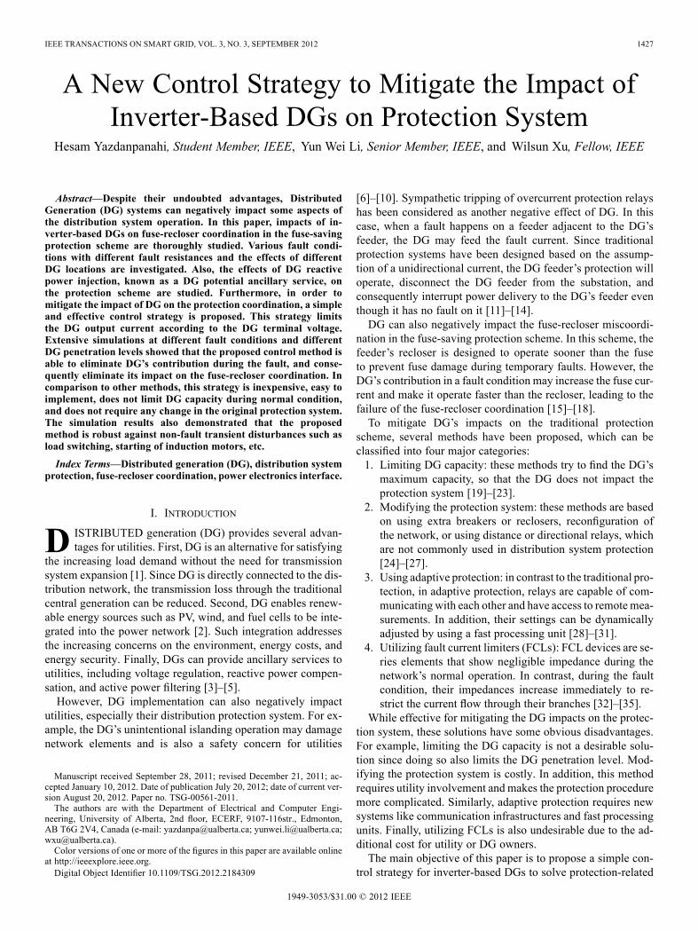
TABLE IIEEE STD. 1547 REQUIRED RESPONSE TO ABNORMAL VOLTAGE CONDITIONS
voltage grid connection standards like [50], [51], distributed re-sources are forced to stay connected to the grid during the fault,and support the grid voltage by injecting reactive power. Nowa-days, such re-evaluation is going to be extended to medium-voltage grids as well [52], [53],where the DG is required to stay connected and provide reactivepower for network during voltage sag. Owing to the fact that thefuse saving scheme is a commonly used protection method inthese medium-voltage networks, satisfying these new require-ments by DG could worsen the miscoordination problem. So,compatibility of new codes for DG interconnection to grid withover-current protection system should be carefully taken intoaccount. Also, the development of DG control strategy that cansatisfy both requirements would be very desirable.
IV. THE PROPOSED INVERTER CURRENT CONTROL STRATEGY
To mitigate the impacts of DG on the fuse-recloser coordina-tion, a simple and effective DG current control strategy is pro-posed in this section.In common practice, the inverter’s current during a
low-impedance fault is restricted up to twice its nominalcurrent [54]. The ideal way to eliminate the impact of DGon the protection system is to detect the fault and trip all theconverters in that protection zone. However, converters areunable to differentiate between fault conditions and short-termdisturbances such as load switching. Therefore, convertertripping in all abnormal conditions may lead to unnecessarypower-delivery interruptions.One way to ride through short-term disturbances and avoid
excessive nuisance tripping is to introduce allowed time delay,as is shown in Table I. If the abnormal condition remains afterthe delay, according to IEEE std. 1547 [48], the converter shouldbe tripped and then reconnected 5 min after the system has re-turned to its normal condition.Nowadays, fast automatic reclosers open and reclose in less
than 6 cycles after fault occurrence, so the above time delaysmay not be effective; i.e., during the reclosing, DG still con-tributes to the arching fault. In addition, decreasing these de-lays may cause excessive nuisance tripping due to short-termdisturbances.One idea to simultaneously solve the miscoordination
problem and ride through short-term disturbances is to reducethe converter current according to the severity of the abnor-mality instead of completely blocking the converter. In thiscase, the converters near the fault location, which will producethe greatest impact on the protection system, experience themost voltage deviation from the normal boundaries and shouldsignificantly decrease their fault current contribution. On the
Fig. 6. Proposed strategy to determine inverter reference current.
other hand, the more distant DG units, which have no substan-tial effect on the protection system, can continue their powerdelivery.To implement the above-mentioned current-control strategy
according to the DG terminal voltage, the DG’s reference cur-rent can be determined as in (10)
for
for
(10)
where is the converter reference current, is the max-imum output current that happens at (thelower boundary for normal operation according to Table I),
is the rms voltage at the DG connection node,is the output desired power and and are constants to bedetermined.Generally the value of determines the sensitivity of the con-
trol scheme to a voltage change. A larger value of leads tomore obvious output current reduction with a voltage sag. How-ever, too large will cause the control scheme over sensitive toeven a small voltage disturbance. With the above consideration,
is selected in this work. Once the value of is chosen,the coefficient can be determined in such a way that the refer-ence current in (10) remains to be a continuous function around
; i.e., can be obtained from (11), whichgives when .
(11)
Fig. 6 shows the flow chart illustrating the reference currentdetermination procedure.
V. SIMULATION INVESTIGATION RESULTS
A. Performance During Low-Impedance Fault Condition
To investigate the ability of the proposed strategy to main-tain fuse-saving coordination, a 13-node test feeder system (seeFig. 7) [55] was constructed by using MATLAB/SIMULINK.A recloser was mounted at the substation, and an inverter-basedDG was connected at node 645. The simple current-controlledvoltage source inverter model in [23] is considered in this work.The DG’s effect on the coordination between the recloser and
YAZDANPANAHI et al.: A NEW CONTROL STRATEGY TO MITIGATE THE IMPACT OF INVERTER-BASED DGS 1431
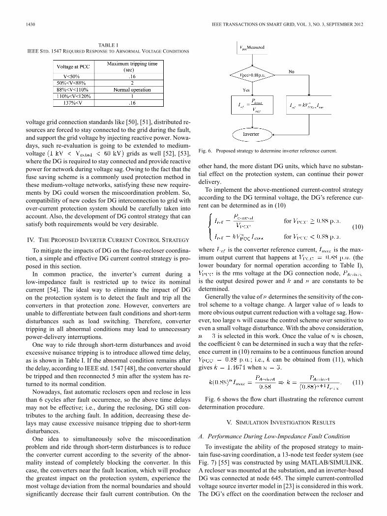
Fig. 7. IEEE 13-node test feeder system [55].
Fig. 8. Fuse-recloser coordination in the simulated system.
Fig. 9. Difference between fuse and recloser operation time after adding DGfor 0.01 fault.
the fuse on 645–646 was studied for faults that occur in themiddle of 645–646. Fig. 8 shows the time-current characteristiccurves of the recloser and fuse used in simulations.In the simulated system, point occurs for fault resistance
of 0.01 , and point occurs for fault resistance of 11.5 .In other words, the fuse and recloser operate properly for faultresistances between 0.01 to 11.5 . For faults with resistancelower than 0.01 , the fuse will operate faster than the recloser,and the use of fuse-saving scheme is not feasible.Fig. 9 shows the consequence of adding DG at different pen-
etration levels on theovercurrent coordination when a 0.01 fault occurs. As Fig. 9reveals, after adding DG even at low penetration levels, the fuseoperates faster than the recloser, and the protection coordinationis lost.This problem will appear in situations with even higher fault
resistances. Fig. 10 shows that miscoordination occurs in a faultwith 0.1 resistance in the presence of DG at high penetrationlevels. As shown, although the fault resistance is higher thanthe one in point , adding DG at penetration levels higher than70% will cause miscoordination.
Fig. 10. Difference between fuse and recloser operation time after adding DGfor 0.1 fault.
Fig. 11. Intentional phase shift in DG current during voltage sag to supportvoltage.
Fig. 12. Difference between fuse and recloser operation time for 0.01 faultwith pi/2 phase shift in inverter current.
To investigate the impact of reactive power injection on theprotection coordination and confirm the analysis of the previoussections, the DG control scheme was modified so that the DGprovided active power during normal conditions, but injected afully reactive current when it experienced a voltage sag
. Fig. 11 shows the PCC’s voltage magnitude and theDG current phase angle for a fault occuring at . Fig. 12shows the difference between fuse and recloser fast operationtimes under this control scheme, for a 0.01 fault.The comparison between Figs. 9 and 12 reveals that the fuse
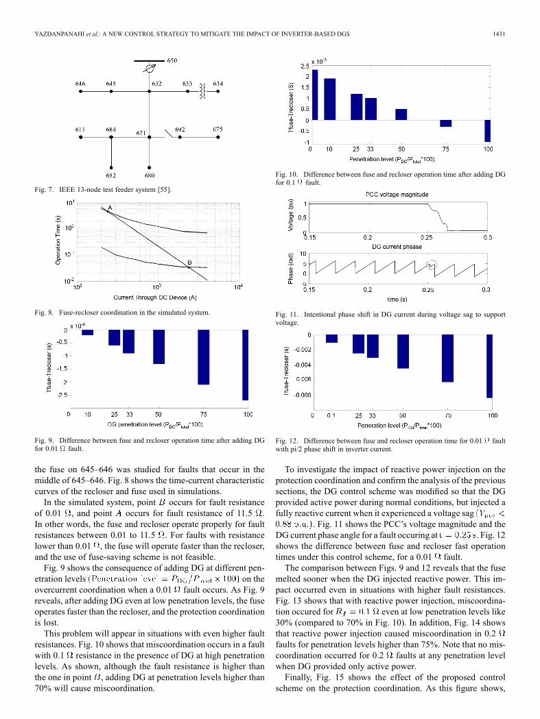
melted sooner when the DG injected reactive power. This im-pact occurred even in situations with higher fault resistances.Fig. 13 shows that with reactive power injection, miscoordina-tion occured for even at low penetration levels like30% (compared to 70% in Fig. 10). In addition, Fig. 14 showsthat reactive power injection caused miscoordination in 0.2faults for penetration levels higher than 75%. Note that no mis-coordination occurred for 0.2 faults at any penetration levelwhen DG provided only active power.Finally, Fig. 15 shows the effect of the proposed control
scheme on the protection coordination. As this figure shows,
1432 IEEE TRANSACTIONS ON SMART GRID, VOL. 3, NO. 3, SEPTEMBER 2012
Fig. 13. Difference between fuse and recloser operation time for 0.1 faultwith pi/2 phase shift in inverter current.
Fig. 14. Difference between fuse and recloser operation time for 0.2 faultwith pi/2 phase shift in inverter current.
Fig. 15. Difference between fuse and recloser operation time for 0.01 faultwith inverter current reduction control.
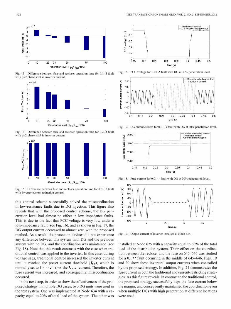
this control scheme successfully solved the miscoordinationin low-resistance faults due to DG injection. This figure alsoreveals that with the proposed control scheme, the DG pen-etration level had almost no effect in low impedance faults.This is due to the fact that PCC voltage is very low under alow-impedance fault (see Fig. 16), and as shown in Fig. 17, theDG output current decreased to almost zero with the proposedmethod. As a result, the protection devices did not experienceany difference between this system with DG and the previoussystem with no DG, and the coordination was maintained (seeFig. 18). Note that this result contrasts with the case when tra-ditional control was applied to the inverter. In this case, duringvoltage sags, traditional control increased the inverter currentuntil it reached the preset current threshold , which isnormally set to the current. Therefore, thefuse current was increased, and consequently, miscoordinationoccurred.In the next step, in order to show the effectiveness of the pro-
posed strategy in multiple DG cases, two DG units were used inthe test system. One was implemented at Node 634 with a ca-pacity equal to 20% of total load of the system. The other was
Fig. 16. PCC voltage for 0.01 fault with DG at 30% penetration level.
Fig. 17. DG output current for 0.01 fault with DG at 30% penetration level.
Fig. 18. Fuse current for 0.01 fault with DG at 30% penetration level.
Fig. 19. Output current of inverter installed at Node 634.
installed at Node 675 with a capacity equal to 60% of the totalload of the distribution system. Their effect on the coordina-tion between the recloser and the fuse on 645–646 was studiedfor a 0.1 fault occurring in the middle of 645–646. Figs. 19and 20 show these inverters’ output currents when controlledby the proposed strategy. In addition, Fig. 21 demonstrates thefuse current in both the traditional and current-restricting strate-gies. As this figure reveals, in contrast to the traditional control,the proposed strategy successfully kept the fuse current belowthe margin, and consequently maintained the coordination evenwhen multiple DGs with high penetration at different locationswere used.
YAZDANPANAHI et al.: A NEW CONTROL STRATEGY TO MITIGATE THE IMPACT OF INVERTER-BASED DGS 1433
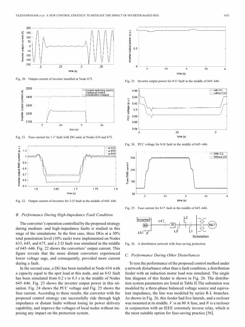
Fig. 20. Output current of inverter installed at Node 675.
Fig. 21. Fuse current for 1 fault with DG units at Nodes 634 and 675.
Fig. 22. Output current of inverters for 2- fault in the middle of 645–646.
B. Performance During High-Impedance Fault Condition
The converter’s operation controlled by the proposed strategyduring medium- and high-impedance faults is studied in thisstage of the simulations. In the first case, three DGs at a 30%total penetration level (10% each) were implemented on Nodes633, 645, and 675, and a 2- fault was simulated in the middleof 645–646. Fig. 22 shows the converters’ output current. Thisfigure reveals that the more distant converters experiencedlower voltage sags, and consequently, provided more currentduring a fault.In the second case, a DG has been installed at Node 634 with
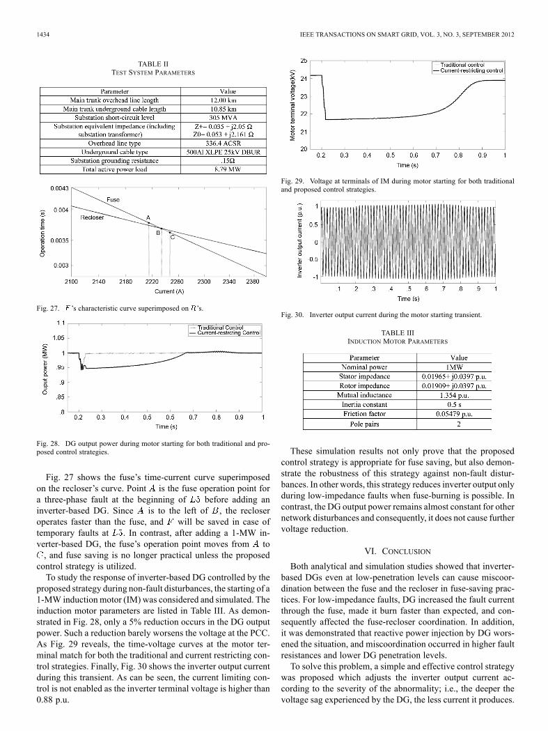
a capacity equal to the spot load at this node, and an 8- faulthas been simulated from 0.2 s to 0.3 s in the middle of Nodes645–646. Fig. 23 shows the inverter output power in this sit-uation. Fig. 24 shows the PCC voltage and Fig. 25 shows thefuse current. According to these results, the converter with theproposed control strategy can successfully ride through highimpedance or distant faults without losing its power deliverycapability, and improve the voltages of local nodes without im-posing any impact on the protection system.
Fig. 23. Inverter output power for 8- fault in the middle of 645–646.
Fig. 24. PCC voltage for 8- fault in the middle of 645–646.
Fig. 25. Fuse current for 8- fault in the middle of 645–646.
Fig. 26. A distribution network with fuse-saving protection.
C. Performance During Other Disturbances
To test the performance of the proposed control method undera network disturbance other than a fault condition, a distributionfeeder with an induction motor load was simulated. The singleline diagram of this feeder is shown in Fig. 26. The distribu-tion system parameters are listed in Table II.The substation wasmodeled by a three-phase balanced voltage source and equiva-lent impedance, the line was modeled by series R-L branches.As shown in Fig. 26, this feeder had five laterals, and a recloserwas mounted at its middle. is an 80 A fuse, and is a recloserin conjunction with an IEEE extremely inverse relay, which isthe most suitable option for fuse-saving practice [56].
1434 IEEE TRANSACTIONS ON SMART GRID, VOL. 3, NO. 3, SEPTEMBER 2012
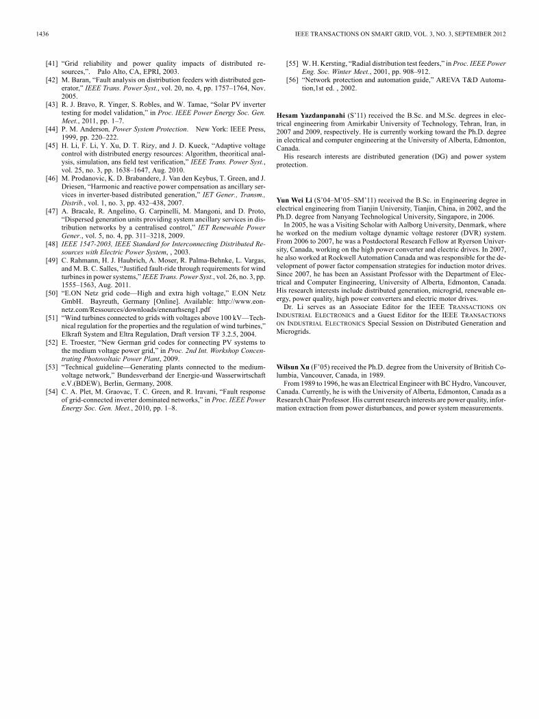
TABLE IITEST SYSTEM PARAMETERS
Fig. 27. ’s characteristic curve superimposed on ’s.
Fig. 28. DG output power during motor starting for both traditional and pro-posed control strategies.
Fig. 27 shows the fuse’s time-current curve superimposedon the recloser’s curve. Point is the fuse operation point fora three-phase fault at the beginning of before adding aninverter-based DG. Since is to the left of , the recloseroperates faster than the fuse, and will be saved in case oftemporary faults at . In contrast, after adding a 1-MW in-verter-based DG, the fuse’s operation point moves from to, and fuse saving is no longer practical unless the proposed
control strategy is utilized.To study the response of inverter-based DG controlled by the
proposed strategy during non-fault disturbances, the starting of a1-MW induction motor (IM) was considered and simulated. Theinduction motor parameters are listed in Table III. As demon-strated in Fig. 28, only a 5% reduction occurs in the DG outputpower. Such a reduction barely worsens the voltage at the PCC.As Fig. 29 reveals, the time-voltage curves at the motor ter-minal match for both the traditional and current restricting con-trol strategies. Finally, Fig. 30 shows the inverter output currentduring this transient. As can be seen, the current limiting con-trol is not enabled as the inverter terminal voltage is higher than0.88 p.u.
Fig. 29. Voltage at terminals of IM during motor starting for both traditionaland proposed control strategies.
Fig. 30. Inverter output current during the motor starting transient.
TABLE IIIINDUCTION MOTOR PARAMETERS
These simulation results not only prove that the proposedcontrol strategy is appropriate for fuse saving, but also demon-strate the robustness of this strategy against non-fault distur-bances. In other words, this strategy reduces inverter output onlyduring low-impedance faults when fuse-burning is possible. Incontrast, the DG output power remains almost constant for othernetwork disturbances and consequently, it does not cause furthervoltage reduction.
VI. CONCLUSION
Both analytical and simulation studies showed that inverter-based DGs even at low-penetration levels can cause miscoor-dination between the fuse and the recloser in fuse-saving prac-tices. For low-impedance faults, DG increased the fault currentthrough the fuse, made it burn faster than expected, and con-sequently affected the fuse-recloser coordination. In addition,it was demonstrated that reactive power injection by DG wors-ened the situation, and miscoordination occurred in higher faultresistances and lower DG penetration levels.To solve this problem, a simple and effective control strategy
was proposed which adjusts the inverter output current ac-cording to the severity of the abnormality; i.e., the deeper thevoltage sag experienced by the DG, the less current it produces.

YAZDANPANAHI et al.: A NEW CONTROL STRATEGY TO MITIGATE THE IMPACT OF INVERTER-BASED DGS 1435
The simulation results showed that this scheme successfullymitigated the miscoordination problem during the fault con-dition. Another advantage of this control strategy is that it isrobust enough against non-fault disturbances; i.e., it avoids nui-sance reduction in DG power delivery. As an example, it wasshown that the inverter output power remained almost constantduring voltage disturbances like those caused by starting largeinduction motors.
REFERENCES[1] A. Piccolo and P. Siano, “Evaluating the impact of network invest-
ment deferral on distributed generation expansion,” IEEETrans. PowerSyst., vol. 24, no. 3, pp. 1559–1567, Aug. 2009.
[2] J. M. Guerrero, F. Blaabjerg, T. Zhelev, K. Hemmes, E. Manmasson, S.Jemei, M. P. Comech, R. Granadino, and J. I. Frau, “Distributed gen-eration: Toward a new energy paradigm,” IEEE Ind. Electron. Mag.,vol. 4, no. 1, pp. 52–64, Mar. 2010.
[3] M. Triggianese, F. Liccardo, and P. Marino, “Ancillary services per-formed by distributed generation in grid integration,” inProc. Int. Conf.Clean Electr. Power, 2007, pp. 164–170.
[4] J. He, Y. W. Li, and S. Munir, “A flexible harmonic control approachthrough voltage controlled DG-grid interfacing converters,” IEEETrans. Ind. Electron., vol. 59, no. 1, pp. 444–455, Jan. 2012.
[5] J. He, S. Munir, and Y. W. Li, “Opportunities for power qualityimprovement through DG-grid interfacing converters,” in Int. PowerElectron. Conf. (IPEC’10), in Proc. IEEE ECCE-Asia, 2010, pp.1657–1664.
[6] X. Wang, W. Freitas, and W. Xu, “Dynamic non-detection zones ofpositive feedback anti-islanding methods for inverter-based distributedgenerators,” IEEE Trans. Power Del., vol. 26, no. 2, pp. 1145–1155,Apr. 2011.
[7] A. H. Kasem Alaboudy and H. H. Zeineldin, “Islanding detection forinverter-based DG coupled with frequency-dependent static load,”IEEE Trans. Power Del., vol. 26, no. 2, pp. 1053–1063, Apr. 2011.
[8] H. Vahedi, R. Noroozian, A. Jalilvand, and G. B. Gharehpetion , “Anew method for islanding detection of inverter-based distributed gen-eration using DC-link voltage contro,” IEEE Trans. Power Del., vol.26, no. 2, pp. 1176–1186, Apr. 2011.
[9] H. H. Zeineldin, “A Q-f droop curve for facilitating islanding detectionof inverter-based distributed generation,” IEEE Trans. Power Elec-tron., vol. 24, no. 3, pp. 665–673, Mar. 2009.
[10] S. H. Lee and J. W. Park, “New islanding detection method forinverter-based distributed generation considering its switching fre-quency,” IEEE Trans. Ind. Appl., vol. 46, no. 5, pp. 2089–2098,Sep./Oct. 2010.
[11] W. El-Khattam and T. S. Sidhu, “Restoration of directional overcur-rent relay coordination in distributed generation systems utilizing faultcurrent limiter,” IEEE Trans. Power Del., vol. 23, no. 2, pp. 576–585,Apr. 2008.
[12] J. C. Gómez andM.M.Morcos, “Coordination of voltage sag and over-current protection in DG system,” IEEE Trans. Power Del., vol. 20, no.1, pp. 214–218, Jan. 2005.
[13] W. El-Khattam and T. S. Sidhu, “Resolving the impact of distributedrenewable generation on directional overcurrent relay coordination: Acase study,” IET Renew. Power Gener., vol. 3, no. 4, pp. 415–425,2009.
[14] C. J. Mozina, “A tutorial on the impact of distributed generation (DG)on distribution systems,” in Proc. Protective Relay Engineers Annu.Conf., 2008, pp. 591–609.
[15] R. A. Walling, R. Saint, R. C. Dugan, J. Burke, and L. A. Kojovic,“Summary of distributed resources impact on power delivery system,”IEEE Trans. Power Del., vol. 23, no. 3, pp. 1636–1644, Jul. 2008.
[16] H. Cheung, A. Hamlyn, L. Wang, C. Yang, and R. Cheung, “Investi-gations of impacts of distributed generation on feeder protection,” inProc. IEEE Power Energy Soc. Gen. Meet., 2009, pp. 1–7.
[17] R. C. Dugan, T. S. Key, and G. J. Ball, “Distributed resources stan-dards,” IEEE Ind. Appl. Mag., vol. 12, pp. 27–34, Feb. 2006.
[18] M. H. Kim, S. H. Lim, J. F. Moon, and J. C. Ki, “Method of recloser-fuse coordination in a power distribution system with superconductingfault current limite,” IEEE Trans. Appl. Supercond., vol. 20, no. 3, pp.1164–1167, Jun. 2010.
[19] T. Seegers et al., “Impact of distributed resources on distribution relayprotection,” Rep. to Line Protection Subcommitee, Power SystemRelay Committee, Power Engineering Society, IEEE, 2004.
[20] S. Chaitusaney and A. Yokoyama, “An appropriate distributed gen-eration sizing considering recloser-fuse coordination,” in Proc. IEEETransm. Distrib. Conf. Exhib.: Asia Pacific, 2005, pp. 1–6.
[21] S. Chaitusaney and A. Yokoyama, “Prevention of reliability degra-dation from recloser-fuse miscoordination due to distributed gener-atio,” IEEE Trans. Power Del., vol. 23, no. 4, pp. 2545–2554, Oct.2008.
[22] J. Chen, R. Fan, X. Duan, and J. Cao, “Penetration level optimiza-tion for DG considering reliable action of relay protection device con-strains,” in Proc. Int. Conf. Sustainable Power Gener. Supply, 2009,pp. 1–5.
[23] T. K. Abdel-Galil, A. E. B. Abu-Elnien, E. F. El-saadany, A. Girgis, Y.A.-R. I. Mohamed, M. M. A. Salma, and H. H. M. Zeineldin, “Protec-tion coordination planning with distributed generation,” Canmet En-ergy Technology Centre, Varennes, QC, Canada, 2007.
[24] H. B. Funmilayo and K. L. Buyler-Purry, “An approach to mitigate theimpact of distributed generation on the overcurrent protection schemefor radial feeders,” in Proc. IEEE Power Syst. Conf. Expo., 2009, pp.1–11.
[25] F. A. Viawan, D. Karlsson, A. Sannino, and J. Daalde, “Protectionscheme for meshed distribution systems with high penetration of dis-tributed generation,” in Proc. Power Syst. Conf. Adv. Metering, Pro-tection Control, Commun., Distrib. Resources, 2006, pp. 99–104.
[26] I. M. Chilvers, N. Jenkins, and P. A. Crossley, “The use of 11 kV dis-tance protection to increase generation connected to the distributionnetwork,” in Proc. Int. Conf. Develop. Power Syst. Protect., 2004, vol.2, pp. 551–554.
[27] D. Uthitsunthorn and T. Kulworawanichpong, “Distance protection ofa renewable energy plant in electric power distribution systems,” inProc. Int. Conf. Power Syst. Technol., 2010, pp. 1–4.
[28] H.Wan, K. K. Li, andK. P.Wong, “An adaptive multiagent approach toprotection relay coordination with distributed generators in industrialpower distribution system,” IEEE Trans. Ind. Appl., vol. 46, no. 5, pp.2118–2124, Sep./Oct. 2010.
[29] S. A. M. Javadian, R. Tamizkar, and M. R. Haghifam, “A protectionand reconfiguration scheme for distribution networks with DG,” inProc. PowerTech, 2009, pp. 1–8.
[30] J. Ma, J. Li, and Z. Wang, “An adaptive distance protection scheme fordistribution system with distributed generation,” in Proc. 5th Int. Conf.Critical Infrastruct., 2010, pp. 1–4.
[31] M. Baren and I. El-Markabi, “Adaptive overcurrent protection fordistribution feeders with distributed generators,” in Proc. Power Syst.Conf. Expo., 2004, vol. 2, pp. 715–719.
[32] W. El-Khattam and T. S. Sidhu, “Restoration of directional overcur-rent relay coordination in distributed generation systems utilizing faultcurrent limiter,” IEEE Trans. Power Del., vol. 23, no. 2, pp. 576–585,Apr. 2008.
[33] M. M. R. Ahmed, G. Putrus, L. Ran, and R. Penlington, “Developmentof a prototype solid-state fault-current limiting and interupting devicefor low-voltage distribution networks,” IEEE Trans. Power Del., vol.21, no. 4, pp. 1997–2005, Oct. 2006.
[34] H. Yamaguchi and T. Kataoka, “Current limiting characteristics oftransformer type superconducting fault current limiter with shuntimpedance and inductive load,” IEEE Trans. Power Del., vol. 23, no.4, pp. 2545–2554, Oct. 2008.
[35] Y. Zhang and R. A. Dougal, “Novel dual-FCL connection for addingdistributed generation to a power distribution utility,” IEEE Trans.Appl. Supercond., vol. 21, no. 3, pp. 2179–2183, Jun. 2011.
[36] R. Dugan, R. Zavadil, and D. Van Holde, “Interconnection guidelinesfor distributed generation, E SOURCE & Electrotek Concepts,” Aug.2002 [Online]. Available: http://grouper.ieee.org/groups/scc21/pdfs/ESourceDG_InterconnectionAppGuide.pdf
[37] J. Keller and B. Kroposki, “Understanding fault characteristics of in-verter-based distributed energy sources,” National Renewable EnergyLaboratory, Golden, CO, NREL/TP-550-46698, 2010.
[38] G. Hernandez-Gonzalez and C. Abbey, Effect of Adding DistributedGeneration to Distribution Networks Case Study 3: Protection Co-ordination Consideration with Inverter and Machine Based DGCanmet Energy, Varennes, QC, Canada, Report-2009-043 (RP-TEC)411-MODSIM, 2009.
[39] B. Kroposki et al., “DG power quality, protection and reliability casestudies report,” National Renewable Energy Laboratory, Golden, CO,NREL/SR-560-34635, 2003.
[40] C. Whitakar, J. Newmiller, M. Ropp, and B. Norris, Renewable systeminterconnection study: distributed photovoltaic systems design andtechnology requirements,” Sandia National Laboratories, Livermore,CA, SAND2008-0946, 2008.
1436 IEEE TRANSACTIONS ON SMART GRID, VOL. 3, NO. 3, SEPTEMBER 2012
[41] “Grid reliability and power quality impacts of distributed re-sources,”. Palo Alto, CA, EPRI, 2003.
[42] M. Baran, “Fault analysis on distribution feeders with distributed gen-erator,” IEEE Trans. Power Syst., vol. 20, no. 4, pp. 1757–1764, Nov.2005.
[43] R. J. Bravo, R. Yinger, S. Robles, and W. Tamae, “Solar PV invertertesting for model validation,” in Proc. IEEE Power Energy Soc. Gen.Meet., 2011, pp. 1–7.
[44] P. M. Anderson, Power System Protection. New York: IEEE Press,1999, pp. 220–222.
[45] H. Li, F. Li, Y. Xu, D. T. Rizy, and J. D. Kueck, “Adaptive voltagecontrol with distributed energy resources: Algorithm, theoritical anal-ysis, simulation, ans field test verification,” IEEE Trans. Power Syst.,vol. 25, no. 3, pp. 1638–1647, Aug. 2010.
[46] M. Prodanovic, K. D. Brabandere, J. Van den Keybus, T. Green, and J.Driesen, “Harmonic and reactive power compensation as ancillary ser-vices in inverter-based distributed generation,” IET Gener., Transm.,Distrib., vol. 1, no. 3, pp. 432–438, 2007.
[47] A. Bracale, R. Angelino, G. Carpinelli, M. Mangoni, and D. Proto,“Dispersed generation units providing system ancillary services in dis-tribution networks by a centralised control,” IET Renewable PowerGener., vol. 5, no. 4, pp. 311–3218, 2009.
[48] IEEE 1547-2003, IEEE Standard for Interconnecting Distributed Re-sources with Electric Power System, , 2003.
[49] C. Rahmann, H. J. Haubrich, A. Moser, R. Palma-Behnke, L. Vargas,andM. B. C. Salles, “Justified fault-ride through requirements for windturbines in power systems,” IEEE Trans. Power Syst., vol. 26, no. 3, pp.1555–1563, Aug. 2011.
[50] “E.ON Netz grid code—High and extra high voltage,” E.ON NetzGmbH. Bayreuth, Germany [Online]. Available: http://www.eon-netz.com/Ressources/downloads/enenarhseng1.pdf
[51] “Wind turbines connected to grids with voltages above 100 kV—Tech-nical regulation for the properties and the regulation of wind turbines,”Elkraft System and Eltra Regulation, Draft version TF 3.2.5, 2004.
[52] E. Troester, “New German grid codes for connecting PV systems tothe medium voltage power grid,” in Proc. 2nd Int. Workshop Concen-trating Photovoltaic Power Plant, 2009.
[53] “Technical guideline—Generating plants connected to the medium-voltage network,” Bundesverband der Energie-und Wasserwirtschafte.V.(BDEW), Berlin, Germany, 2008.
[54] C. A. Plet, M. Graovac, T. C. Green, and R. Iravani, “Fault responseof grid-connected inverter dominated networks,” in Proc. IEEE PowerEnergy Soc. Gen. Meet., 2010, pp. 1–8.
[55] W. H. Kersting, “Radial distribution test feeders,” in Proc. IEEE PowerEng. Soc. Winter Meet., 2001, pp. 908–912.
[56] “Network protection and automation guide,” AREVA T&D Automa-tion,1st ed. , 2002.
Hesam Yazdanpanahi (S’11) received the B.Sc. and M.Sc. degrees in elec-trical engineering from Amirkabir University of Technology, Tehran, Iran, in2007 and 2009, respectively. He is currently working toward the Ph.D. degreein electrical and computer engineering at the University of Alberta, Edmonton,Canada.His research interests are distributed generation (DG) and power system
protection.
Yun Wei Li (S’04–M’05–SM’11) received the B.Sc. in Engineering degree inelectrical engineering from Tianjin University, Tianjin, China, in 2002, and thePh.D. degree from Nanyang Technological University, Singapore, in 2006.In 2005, he was a Visiting Scholar with Aalborg University, Denmark, where
he worked on the medium voltage dynamic voltage restorer (DVR) system.From 2006 to 2007, he was a Postdoctoral Research Fellow at Ryerson Univer-sity, Canada, working on the high power converter and electric drives. In 2007,he also worked at Rockwell Automation Canada and was responsible for the de-velopment of power factor compensation strategies for induction motor drives.Since 2007, he has been an Assistant Professor with the Department of Elec-trical and Computer Engineering, University of Alberta, Edmonton, Canada.His research interests include distributed generation, microgrid, renewable en-ergy, power quality, high power converters and electric motor drives.Dr. Li serves as an Associate Editor for the IEEE TRANSACTIONS ON
INDUSTRIAL ELECTRONICS and a Guest Editor for the IEEE TRANSACTIONSON INDUSTRIAL ELECTRONICS Special Session on Distributed Generation andMicrogrids.
Wilsun Xu (F’05) received the Ph.D. degree from the University of British Co-lumbia, Vancouver, Canada, in 1989.From 1989 to 1996, he was an Electrical Engineer with BCHydro, Vancouver,
Canada. Currently, he is with the University of Alberta, Edmonton, Canada as aResearch Chair Professor. His current research interests are power quality, infor-mation extraction from power disturbances, and power system measurements.