fatigue performance and mechanical reliability of cemented
TRANSCRIPT

TALLINN UNIVERSITY OF TECHNOLOGYTHESIS OF MATERIALS ENGINEERING
Fatigue Performance and Mechanical Reliability ofCemented Carbides
IRINA PREIS
TALLINN 2004

Faculty of Mechanical EngineeringDepartment of Materials Engineering
TALLINN UNIVERSITY OF TECHNOLOGY
Dissertation is accepted for the defence of the degree of Doctor of Philosophy inEngineering on November 25, 2004
Supervisor:Prof. Dr. Jakob Kübarsepp, Faculty of Mechanical EngineeringAdviser: Dr. Heinrich Klaasen, Faculty of Mechanical Engineering
Opponents:Dr. Michal Besterci, Institute of Materials Research of SAS, Kosice, Slovak RepublicDr. Mart Viljus, Tallinn University of Technology, Estonia
Commencement: December 28, 2004
Declaration
I declare that the current thesis is my original unaided work. It is being submitted forthe Degree of Doctor of Philosophy in Engineering at Tallinn University ofTechnology. It has not been submitted before for any degree or examination in anyother university.
Signature:Date:
© Irina Preis 2004ISSNISBN

3
PREFACEThe author gratefully acknowledges the Estonian Science Foundation, The Ministry ofEducation and Research of Estonia, Development Fund of Tallinn University ofTechnology and CIMO Foundation (Finland) for financial support of the presentresearch.The author would like to express her deepest gratitude to her supervisor, Prof. Dr.Jakob Kübarsepp, for fruitful discussions and sharing academic knowledge, for hispermanent support during last six years of our productive collaboration. I also wouldlike to thank Dr. Heinrich Klaasen for the encouragement of my doctoral studies, forhis ideas in planning and evaluation of testing procedures. I would also like to thankmy student and colleague MSc. Fjodor Sergejev for his help, contribution and activityin our research.I would also like to give my special thanks to Prof. Dr. Gary Marquis, Head ofLaboratory of Steel Structures of Lappeenranta University of Technology in Finlandfor his assistance and guidance helped in numerous technical issues.I would like to thank my adviser in a field of accelerated testing approach Dr. ViktorStrizhak for his guidance and collaboration.Special acknowledgements are given to the Testing Laboratory of the Department ofMaterials Engineering, Tallinn University of Technology and personally to the Headof Laboratory MSc. Riho Päärsoo and my collegue MSc. Renno Veithal for theguidance and support.I would also like to thank my colleague MSc. Rainer Traksmaa, from The MaterialsResearch Center of Tallinn University of Technology for his assistance and support inmicrofractographic investigations done.I wish to express my most gratitude to my family and friends for their continuousdirect and indirect support, patience, understanding and encouragement on thedifferent stage of this work.

4
KOKKUVÕTEUuriti erineva koostise ja struktuuriga kermetite (WC-kõvasulamid, TiC-kermised)töövõimet ja purunemismehhanismi tsüklilise (väsimus, stantsimine) koormamisetingimustes.Arendati välja kiirendatud väsimuse tugevuse hindamise meetod kermetite töövõimehindamiseks ning näideti et materjali vastupanu väsimuslikule purunemisele määrabühelt poolt tema väsimuspiir ja teiselt tema väsimustundlikkus (Wöhler-kõvera kalle).Viidi läbi kermetite väsimus käitumise statistiline arutelu selgitamiseks välja nendeWeibull modulite erinevused ning viimaste seos väsimustudnlikusega.Viidi läbi uuritavate kermetite ekspluatatsioonilised katsed, selgitamiseks välja nendetöövõime (kulumiskindlus) survega töötlemise operatsioonides (lehtstantsimisel) jaselle seos väsimusega.Näideti, et suure töövõimega (stantsimis eaga) kermetit iseloomustab kõrge vastupanuadhesioonkulumisele ja väike väsimustundlikkus.Viidi läbi mikrostruktuursed (SEM) ja röntgenstruktuursed (XRD) uuringud ningselgitati välja purunemismehhanismi erinevused ja sarnasused erinevatel kermetitelväsimusliku (tsüklilise) ja monotoonse koormamise tingimustes.

5
ABSTRACTThe fatigue performance of cemented carbides with different composition, structureand properties has been investigated. It was shown that the differences in wearresistance between cermet materials with equal hardness and volume fraction of bindercontent can be attributed to differences in their resistance to fracture under cyclicloading conditions.The accelerated fatigue testing procedure was designed and applied to assess thefatigue characteristics of selected materials. The important constitutive materialconstants for two major cemented carbides WC- and TiC- base utilised as toolmaterials in metal forming operations were calculated using an accelerated testingapproach.Standard fatigue testing in three-point bending showed that the resistance of materialstested to the damage processes under cyclic loading is much lower than that undermonotonic one. The different slopes of the Wöhler plots expressed the differentfatigue sensitivity of material structure. The estimated endurance limits and Weibullstatistics were presented as well.The durability tests carried out as the service condition tests showed that the blankingperformance of the cemented carbides is controlled by their resistance to adhesivewear (primarily that of its binder) and to the propagation of fatigue cracks.The statistical considerations of fatigue behavior were directed to explain thedifferences in Weibull modulus numbers for different testing schemes (tension, fourpoint and three point bending loading), which are characterized by the differences inthe stress field uniformity.The microfractography studies by means of SEM and XRD analysis of fatigued andworn surfaces revealed the certain similarities in the micromechanisms of fatigue andwear. At the same time, an important aspect of accumulation of the elastic strainenergy and plastic deformation (at cycling and monotonic loading) of different carbidephases explains the difference in their fatigue performance. The latter statementconfirms that mechanical and service reliability of TiC-base cemented carbides can becompared with that of traditional tungsten carbide composites in spite of the lowermagnitudes of mechanical characteristics, such as transverse rupture strength, proofstress and Young’s modulus.

6
TABLE OF CONTENTPREFACE............................................................................................................ 3KOKKUVÕTE .................................................................................................... 4ABSTRACT......................................................................................................... 5TABLE OF CONTENT....................................................................................... 6LIST OF PUBLICATIONS................................................................................. 7THE AUTHOR’S CONTRIBUTION TO PUBLICATIONS............................. 8INTRODUCTION ............................................................................................... 91 REVIEW OF FATIGUE DATA OF CEMENTED CARBIDES...............11
1.1 Fatigue testing approaches ..........................................................................111.2 Materials and testing procedures .................................................................121.3 Fatigue crack growth behaviour of cemented carbides .................................171.4 Microstructural aspects and fractography of fatigue crack growth in cemented
carbides ....................................................................................................201.5 Mechanical and tribological behaviour of cemented carbides.......................221.6 Statistical consideration of cemented carbides fatigue performance .............241.7 Objectives and strategies .............................................................................27
2 EXPERIMENTAL PROGRAM.................................................................282.1 Materials ....................................................................................................282.2 Accelerated fatigue testing ..........................................................................302.3 Wear testing ................................................................................................322.4 Fatigue testing.............................................................................................332.5 Durability testing in blanking ......................................................................352.6 Fatigue and bending strength: related fractography......................................35
3 STATISTICAL ASPECTS OF FATIGUE PERFORMANCE ANDENDURANCE LIMIT PREDICTION...........................................................403.1 Statistical strength, testing procedures and Weibull modulus........................403.2 Prediction of the lower bound of the scatter in fatigue strength: Murakami
approach ....................................................................................................41CONCLUSIONS.................................................................................................43REFERENCES ...................................................................................................45SYMBOLS AND ABBREVIATIONS................................................................48APPENDIX A .....................................................................................................50APPENDIX B......................................................................................................61CURRUCULUM VITAE (CV)...........................................................................62ELULOOKIRJELDUS (CV)..............................................................................65

7
LIST OF PUBLICATIONS
The present dissertation is based on the following papers, which are referred to in thetext by their Roman numerals I-V. As some of the results of recent research have notbeen published yet, this thesis was substantially enlarged.
I. Preis, I., Kübarsepp, J. and Strizhak, V. - Preliminary assessment of durabilityof hardmetals and cermets. Proceedings of the 3rd Inernational Conference onIndustrial Engineering – New Challenges to SME, April 27-29, 2000, Tallinn,Estonia, pp.175-178.
II. Preis, I. - Statistical strength of brittle materials: test methods and Weibullmodulus. Proceedings of 2nd International Conference - New Challenges toSME, April 25-27, 2002, Tallinn, Estonia, pp.205-208.
III. Klaasen, H., Kübarsepp, J. and Preis, I., - Wear behaviour, durability andcyclic strength of TiC-base cermets. - Material Science and Technology, 20,August, 2004, pp.1006-1010.
IV. Klaasen, H., Kübarsepp, J. and Preis, I. - Toughness and durability ofcemented carbides. Proceedings of the International Conference ondeformation and fracture of structural PM materials, September 15-18, 2002,Slovak Republic, IMR SAS – European Powder Metallurgy Association,Kosice, Vol. 1, pp.77-83.
V. Klaasen, H., Kübarsepp, J., and Preis, I. - Durability of advanced TiC-basecermets. Proceedings of the Estonian Academy of Science, 2003, 9, 4, pp.272-280.
In addition to this, the results of the research have been discussed on scientificworkshops in Estonia and Finland.In the Appendix B of this thesis, copies of the articles have been included. Reprints ofpapers were made with permission from the publisher.

8
THE AUTHOR’S CONTRIBUTION TO PUBLICATIONS
The contribution of the author of present thesis into the papers listed above is asfollows:
I The author fulfilled the experimental program, including experiments andanalysis, systematically analyzed obtained results and participated in writing thepaper.
II The author developed the theoretical approach and wrote the paper.
III The author herself obtained data of standard fatigue testing under supervisionand cooperation with co-authors.
IV The author contributed by data obtained for fatigue performance and dataconcerning microfractography of failure.
V The author herself obtained data of standard fatigue testing under supervisionand cooperation with co-authors.

9
INTRODUCTIONThe problem of the fatigue strength estimation of wear resistant cemented carbides,particularly hard metals containing natural defects, inclusions or inhomogeneities is ofgreat importance from both a scientific or industrial point of view. These materials arerelated to so-called “structurally brittle” materials group. Therefore, designers areoften hesitant to design components with brittle materials despite advantagesregarding strength, weight and resistance to harsh mechanical loads, thermal andchemical environment. In this context, the research presented is the next attempt toenlarge the knowledge concerned time-dependent degradation of composites underalternating stresses.Thanks to the group of scientists at Erlangen-Nürnberg University rebirth in interest inhard metal fatigue has been detected in the last few decades. The majority of theexperimental work has been done using constant amplitude loading at short and longspectrum of materials life.The obtained data show distinct differences of hard metal behavior under static andalternating loading. Nevertheless, very restricted aspects of the behavior of cementedcarbides consisting of brittle ceramics embedded in a ductile binder phase wereconsidered in some investigations in the past, which dealt with the fatigue resistance(Kreimer, 1971; Loshak, 1984; Shleikofer et al., 1995 and 1996 etc.), fatigue crackgrowth (Torres et al., 2000 and Llanes et al., 2002), interrelations of fatigue crackgrowth and microstructure, influence of the microstructure and of the conditions of thesurface on the fatigue performance, the influence of the plastic zone at the crack tip onthe fatigue and crack resistance (Suresh, 1991).More recent investigations of the fatigue of cemented carbides show that irreversiblemicroscopic changes (micro-crack formation, phase transformation, phase boundarysliding and pore nucleation during fatigue processes) occur in front of the crack tip,analogous to the irreversible sliding processes during the fatigue of ductile materials.In addition different processes, caused by crack closure, crack bridging, and friction ofopposite crack surfaces, have an influence on the fatigue crack growth. Especially, thelatter processes are clearly different in the same materials under static ormonotonously increasing loads.The main goal of this work is to determine and compare the fatigue behaviour of themajor groups of hardmetals: WC-based and TiC-based alloys. The research includesalso an overview of the current experimental program, the most significant results in‘endurance limit’ determination and in the fatigue sensitivity assessment. The aspectsof statistical strength of materials are also the point of interest – the main Weibulldistribution parameters are quantified for both static and cyclic fractures.In order to evaluate quantitatively the effects of defects and inclusions on the fatiguestrength of cemented carbides, Murakami (2002) method firstly was applied. Theresults of equating the lower band of scatter of endurance limit on the basis of binderVicker’s hardness and geometric parameter maxarea showed its excellent

10
convergence with experimental data received from both testing procedures standardfatigue tests and accelerated fatigue ones.Most experimental data on fatigue performance of hard metals and cermets aredirected toward the sheet metals forming – blanking operations. Particularly, the TiC-FeNi composites, developed by the group of Laboratory of Powder Metallurgy inTallinn University of Technology, are the promising candidates for the blanking dies.The observations on functional testing of these materials in the service conditions(blanking) are also presented. The relationship between the main mechanicalcharacteristics like hardness, fracture toughness, plasticity, bending strength, wearresistance and fatigue ones is in-depth study. Microstructural investigations of thefatigue fracture are included in this work.

11
1 REVIEW OF FATIGUE DATA OF CEMENTED CARBIDES1.1 Fatigue testing approachesFatigue data of cemented carbides (hard metals) are extremely limited. While certainstress vs. life (S/N) data has been developed for basic grades, only a few studies of thecyclic constitutive behavior of these alloys have been published.As a rule, fatigue testing of structural materials is introduced within the bounds ofthree main approaches:
• stress-life approach,• strain-life approach,• fracture mechanics approach (fatigue crack growth).
For the most part, the stress-life approach is chosen like a major testing procedure forcemented carbides because of the obvious difficulties in measuring and monitoringstrain during testing (Suresh, 1991). The problem in strain-life fatigue testing is thefeature of a brittle material characterized by very little plastic flow that occurs in thespecimen prior to failure. A fracture mechanics approach was used to develop asuitable phenomenological fatigue law (Sigl et al., 1987). Main applications ofcemented carbides include cases where they are subjected primarily to compressivestresses. Failure in compression is less catastrophic than in tension, and in someaspects qualitative resemblance with metal plasticity is observed. Therefore, themechanics of cracks at present focuses on the numerical simulation of crackscoalescence under the loading conditions of Modes I and II. Crack propagation in theductile binder of WC-based grades is simulated using different modelling strategies(Kenny et al., 1971).The development of the devices assigned for fatigue endurance data of the hard metalsrequires that certain specific application conditions be taken into account, in which themechanical behaviour of hardmetals differs from other alloys. Main conditions may belisted as follows:
• hard metals exhibit much lower resistance towards tensile stresses than tocompressive ones. Therefore, the influence of microstructural defects onmaterial strength can be observed much more effectively in tension than incompression,
• the sensitivity of microstructure caused by material heterogeneity (two phases –hard particle-phase and ductile binder phase),
• very high magnitudes of Young’s modulus (from 470 up to 670 GPa). It meansthat there are no any visible residual strains of bulk specimen during the testingprocedure,
• the brittle manner of fracture and the presence of various defects (pores,inclusions etc.) on the microstructural level. It governs to statistical analysis forthe real-valued assessment of fatigue characteristics. Consequently, the largeamount of specimens must be tested (up to three times more than for steelfatigue investigations),

12
• some parts of hard metal tools are subjected to impact-bending loading in theservice conditions (dies, punches, mining tools, cutting tools etc.). A number ofhard metal tools are prone to damage by cyclic loading (Brookes, 1992).
These considerations were the basis of design and development of special rigs for thefatigue testing of cemented carbides.
1.2 Materials and testing proceduresEarlier investigations deal with fatigue testing of WC-Co alloys with differentcontents of Co phase under three-point bending (3PB) loading conditions (Kreimer,1971) at ambient temperature. The coefficient of cyclic asymmetry R was 0.1. Themaximum fracture stress was measured on the basis of 5⋅106 cycles. The fatigue dataobtained (Fig.1.1) show that the higher the Co-binder content (wt.%) the higher theendurance limit of the grade.
Figure 1.1. Fatigue curves (Wöhler plots) for WC-Co with different cobalt content(Kreimer, 1971)
The influence of carbide grain size was also established: the decrease of the endurancelimit was related to the decrease of grain size of carbide phase or to the duration ofWC and Co powder milling. The endurance limits data are presented in Table 1.1.
Table 1.1 Hardness HRA, transverse rupture strength RTZ and endurance limits Se ofH4, H6 and H8 grades (Kreimer, 1971)
Grade Hardness(HRA) RTZ (MPa) Endurance limit Se, 5⋅10
6
(MPa)
H4 (WC-4% Co) 90 1400 ≈ 1050
H6 (WC-6% Co) 89 1470 ≈ 1160
H8 (WC-8%Co) 88 1510 ≈ 1210
It was assumed that the linear correlation between fatigue endurance limit and staticstrength in tension also exists. The distinctive features of Kreimer’s work were the flatregions of the fatigue curves that are parallel to (log N) axis. This fact shows the

13
possibility of existence of a fatigue limit (physical endurance limit) for hard metals.WC-Co alloys with 6, 12, 20 and 25 wt.% Co content were subjected to torsion-bending cyclic loading. But the majority of fatigue curves obtained from laterinvestigations (Loshak, 1971) showed an evident absence of any flat regions (Fig.1.2).
Figure 1.2 Fatigue curves (Wöhler plots) for (1) WC20%Co, (2) WC15%Co, (3)WC25%Co, (4) WC8%Co, (5) WC6%Co (Loshak, 1984)
The ratio of endurance limit (Se,5⋅106) in cyclic bending and transverse rupture strength
(RTZ) in static bending was equal to 0.7-0.8 (Miyake et al., 1968) and 0.6 (Davies etal., 1972). Such a great difference in the data obtained can be explained, first of all, bythe imperfection of testing methods and techniques used. Usually, only 10-15specimens of hardmetals were tested in the studies considered above and Wöhler’scurves were plotted. Taking into account a considerable scatter of experimental dataone can assume an obvious existence of a specific nature of hard metal fractureresulting from their production technology (Loshak et al., 1972).The two testing devices were designed for the high frequency cyclic loading - up to200 Hz (Loshak, 1984). The loading scheme of both rigs was three-point bending withthe zero-level of minimum stress. The first device was used in the so-called impact-bending tests and the other one was designed for bend cyclic loading.More recent results on fatigue performance of cemented carbides were presented byBrookes (1982). Endurance limits of 600-850 MPa for 108 cycles for WC-Co(5… 25wt%Co) were reported. These stress values lie at around 30% of the transverserupture strengths. The results received by Schedler (1998) who determined endurancelimits for similar materials in the range 30-40% of the RTZ are in agreement with this.The next loading scheme used by a research group from the University of Erlangen-Nurnberg to investigate fatigue performance is a new special cantilever-bendingdevice developed for static, monotonic and cyclic alternating loading (Shleinkofer etal., 1995).A schematic representation of the apparatus used is shown in Figure 1.3, (a).Kennametal Hertel, F.R. Germany, produced the investigated hardmetals and cermets.The samples had the dimensions 1.5×2.5×60 mm for the tests at 22 Hz and 3×4×90mm for the tests at 1Hz and 2Hz. The stress ratio of fully reversed bending load wasR= − 1. The surfaces of all samples were ground in a reproducible oscillating process.

14
(a) (b)Figure 1.3. The scheme of the testing rig used for three load conditions (a) andspecimen preparation (b) for mechanical testing (Shleinkofer et al., 1995) .
The samples were embedded with an epoxy resin in brass tubes (Fig.1.3, b) in order toavoid stress concentration at the transition from sample to the fixing bracket. Thecompositions of the hard metals and cermets tested are given in Table 1.2.The grain size of binder phase was in the range of 1 µm. The sizes of carbide grains,containing Ti, Ta and Nb were in the range of 1.2 to 2.2 µm. The characteristics of thefatigue performance of the alloys investigated are given in Table 1.3.
Table 1.2 Compositions of hard metals and cermets (wt%) (Shleinkofer et al., 1995)Compound Hard metal A Hard metal B Hard metal C Cermet AWC 86.5 82.5 86.5 19.0TiC 2.5 2.0 2.5 -TiN - - - 5.0Ti(C,N) - - 43.0 30(Ta,Nb)C 5.0 3.5 5.0 14Mo2C - - - 8.0Co 6.0 12.0 4.0 10.0Ni - - 2.0 6.0
The results showed that the resistance of hard metals and cermets against damageprocesses are significantly lower under cyclic loads than under static andmonotonously increasing ones. The chemical composition and microstructure of alloyinfluences the resistance to failure.

15
Table 1.3 Inert bending strength and endurance limits of hard metals A, B, C andcermet A (Shleinkofer et al., 1996)
GradeInert bending strength
Sb,0, (MPa)Endurance limit
Se, 107, (MPa)
Hard metal A 2498 ≈ 960Hard metal B 2734 ≈ 900Hard metal C 2547 ≈ 615Cermet A 1835 ≈ 850
When comparing hard metals and cermets, it became clear that the fatigue processoccurs less strongly in cermet A. The slope of the dependency σmax – log Nf (Fig.1.4)is smaller for cermet A than in the results for hardmetals A, B and C. In other words,fatigue sensitivity of cermet is less than that of hard metals.
(a)
(b)Figure 1.4. Wöhler plots of the fatigue life for various types of hardmetals (a) and (b)cermet. (Shleikofer et al., 1996)
The differences in the behaviour were clearer in the classical Wöhler plots (Figs.1.4, aand 1.4,b) and Wöhler plot (Fig.1.5) of relative stress amplitudes σmax/Sb,0 vs. logNf,where instead of σmax, the ration σmax/Sb,0 with the inert bending strength Sb,0 of thematerials are plotted. Higher slopes on this plot indicate higher accumulation of the

16
damage during the cyclic loading. It became clear from the plot that cermet A issuperior in its behavior at higher Nf to the hardmetals. Another point to be highlightedon the plot in Figure1.5: it was expected that one curve runs through 1 at logNf = 0.This is the case for hard metal A. The materials with higher binder content (hard metalB and cermet A) exhibit an intersection at a point below 1 for logNf = 0. It wasassumed that this difference is caused by a damage mechanism, which occurs at ahigher number of cycles in the materials with higher amounts of ductile binder phase.Such a process could be explained as a higher accumulated work hardening anddifferent fatigue processes in the binder phases.
Figure 1.5. Wöhler plots normalized by the inert bending strength (Shleinkofer et al.,1998)
The investigation on the influence of binder content and composition on the fatigueperformance of cemented carbides showed that the WC-Co grades (with 7, 15 and 27wt% of Co) present little influence of the binder content on their fatigue behaviour dueto the localization of damage in shear bands in the binder pools and the facilitatedcrack propagation in the transformed h.c.p.-binder phase or along stacking faults(Kursawe et al., 2001).
(a) (b)Figure 1.6. Wöhler plots for WC-Co (a) and WC-CoNiFe (b) hardmetals (Kursawe etal., 2001)
All these processes are responsible for the minor influence of the binder content on thefatigue behaviour of the WC-Co hard metals. The Wöhler plots in Figure 1.6, (a)

17
exhibit large scatter and almost identical slopes, which causes the Wöhler curves of allthree materials to overlap. A decreasing width of the scatter band could be found withincreasing binder content as the overall nature of the compound becomes moremetallic. The composition CoNiFe-binder (with 7, 15 and 27 wt% Co) also exhibitreduced scatter with increasing binder content but the slopes of the Wöhler curves aredifferent for each hard metal grade (Fig.1.6, b).A clear influence of binder content on the fatigue behaviour of the WC-CoNiFe hardmetals was found. This behaviour was explained with the absence of the binder phasetransformation and the higher ductility of the CoNiFe alloy. The results of mechanicaltesting were confirmed by the results of the FEM simulation based on the plastic flowrules (Munz, et al., 1989). Due to the higher ductility of the CoNiFe binder phase, thezones of plasticity are larger in the WC-CoNiFe hard metals than in the WC-Co ones.Data concerning the endurance limits measured are presented in Table 1.4.
Table 1.4 Inert bending strength and endurance limits of hard metals WC-Co andWC-CoNiFe (Kursawe et al., 2001)
GradeInert bending strength
Sb,0 , (MPa)Endurance limit
Se, 106, (MPa)
WC-7%Co 2840 ≈1200WC-15%Co 3178 ≈1300WC-27%Co 2887 ≈1170WC-7%CoNiFe 2859 ≈1480WC-15%CoNiFe 3122 ≈980WC-27%CoNiFe 2529 ≈770
1.3 Fatigue crack growth behaviour of cemented carbidesWhile there have been several studies addressed to evaluate the fatigue performance ofcemented carbides (mostly for WC-Co grades), only a few investigations have focusedon the fatigue crack growth (FCG) behaviour of these materials (Hoenle et al., 1998;Llanes et al., 2000). Such limited information on FCG characteristics of hard metals isunfortunate, from the viewpoint of effective time-dependent (fatigue) propertytailoring through microstructure control, once it is now well established that sub-critical growth of pre-existing flaws is the controlling stage in the fatigue failure ofthese materials. Several authors have studied the influence of microstructure andfatigue test parameters on the FCG behaviour of WC-Co cemented carbides has beenstudied, for relatively restricted sets of conditions. Although in such investigations astrong dependence of FCG rates on a particularly chosen fracture mechanics parameter(mainly the stress intensity factor range, ∆K) has been always found, none of theapproaches applied for describing FCG kinetics in these materials allows a completerationalization of the concomitant microstructural and testing effects observed(Ishihara et al., 1999; Hiroshe et al., 1997; Almond et al., 1981 etc.)

18
An enhancement of FCG resistance with increasing binder content or carbide grainsize was also reported (Fry et al., 1983). The changes of latter correlating well withcorresponding variations in fracture toughness. Knee and Plumbridge (1984) have alsoobserved similar trends on microstructural effects, for two different load ratios.However, authors noticed such microstructural influence on FCG behaviour lessenswith decreasing crack growth rates, to the limit of measuring crack propagationthresholds independent of both microstructure and toughness.Hirose et al. (1997) discerned FCG kinetics to be significantly affected by both loadratio and WC grain size. This was found to be the case even when plotting crackgrowth data in terms of the effective stress intensity factor range, ∆Keff (after allowingfor crack closure).Finally, Ishihara et al. (1999) found a transition on the dominant fracture mechanicsparameter for describing FCG kinetics, from Kmax, the maximum stress intensityfactor, to ∆K with decreasing crack growth rates.In the main report of results received by Llanes’et al. (2001) investigations, specialattention was paid to analyse the experimental findings with respect to 1) relativedominance of static and cyclic failure modes during stable crack propagation; and 2)fatigue sensitivity, this parameter being defined as the ratio between the applied stressintensity factors corresponding to FCG threshold and the fracture toughness –Kth/KIc.The materials studied were plain WC-Co cemented carbides with differentcombinations of carbide grain size, dWC, and cobalt volume fraction, VCo. Values forcobalt binder thickness, or binder mean free path (λCo) and carbide contiguity (CWC)were estimated by empirical relationships. The effect of load ratio R was evaluatedfrom the FCG behaviour measured under R-values of 0.1, 0.4 and 0.7. Experimentalresults indicated that: 1) WC-Co cemented carbides are markedly sensitive to fatigue;and 2) their FCG rates exhibit an extremely large dependence on Kmax.Torres et al. (2000) conducted investigation and came to the agreement that, a moreclassical and conservative approach on the basis of fatigue limit and fatigue crackgrowth (FCG) threshold, i.e., from an infinite fatigue life viewpoint, appears to bemore appropriate for brittle materials such as cemented carbides. This approach wasimplemented by simply defining critical flaw size under cyclic loading in terms ofFCG threshold. Under this consideration, fatigue limit, Se, was given by maximumstress (Smax) resulting in the threshold intensity factor, Kth, of a small non-propagatingcrack emanating from a defect of critical size, 2lcr, according to relationships of type
the
cr
KSl
∝, (1.1)
And then fatigue limit was estimated from Eq. (1.1), under assumption that strength-controlling flaws are the same, with respect to type, geometry, size and distributionunder monotonic and cyclic loading

19
the TZ
Ic
KS RK
=
, (1.2)where RTZ – is the transverse rupture strength. Such a correlation should not beconsidered as unexpected because it is implicit to the basis sustaining the wholeanalysis: (1) initiation of stable cracks growth as the controlling stage in the fatiguefailure phenomena; and (2) similitude on the fatigue threshold behavior of large andsmall cracks (Torres et al., 2000)All presented correlations were in agreement with practical observations and results ofconducted tests. The agreement between predicted and observed fatigue limits weredescribed as excellent, with errors relative to the experimental values (Table 1.5)always lower than 10%, a finding that yields strong support to the FCG threshold-fatigue limit correlation proposed earlier.
Table 1.5 Predicted and experimentally determined fatigue limit values, in term ofmaximum applied stress, for different load ratios for WC-10 wt% Co (Torres et al.,2000)
Load ratio R Observed fatigue limit Se (MPa) Predicted fatigue limit Se (MPa)0.1 1827±92 17880.4 1783±70 19370.7 2112±70 2265
Furthermore, both fatigue sensitivity and relative prevalence of Kmax over ∆K, as thecontrolling fatigue mechanics parameter, were found to be significantly dependentupon the microstructure. As the mean binder free path increases (Fig.1.7),predominance of static over cyclic failure modes diminishes and a transition from aceramic-like FCG behavior to a metallic-like one occurs (conversely in relation tocontiguity).
Figure 1.7. Fatigue sensitivity – microstructure relationship for WC-Co hardmetals.(m/n ratio from Paris-Erdogan equation) (Llanes et al., 2002)
The trade-off between fracture toughness and FCG resistance becomes morepronounced with increasing binder content and carbide grain size. The observed

20
behavior is attributed to the effective low ductility of the constrained binder and itscompromising role as the toughening and fatigue-susceptible agent in hard metals, thelatter on the basis that cyclic loading degrades or inhibits toughening mechanismsoperative under monotonic loading, i.e. crack bridging and constrained plasticstretching (Llanes et al., 2002).
1.4 Microstructural aspects and fractography of fatigue crack growth incemented carbides
Schlienkofer et al., (1996) observed a stable crack propagation of small natural cracksduring fatigue loading. The compositions of cemented carbides subjected to theinvestigation given in Table 1.6.
Table 1.6 Compositions (wt.%) of the hard metal and cermets subjected tomicrostructural investigations (Schleinkofer et al., 1996)
Compound Hard metal Cermet A Cermet BWC 86.5 19.0 -TiC/TiN 2.5 43.0 -(Ta, Nb)C 5.0 14.0 -Mo2C - 8.0 -(WTiTaNbMo)(C,N) - - 84.0Co 6.0 10.0 10.0Ni - 6.0 6.0
The cracks propagated predominantly in the ductile Co-binder phase, which in itselfundergoes a strong plastic deformation, especially in the ligaments formed behind thecrack tip (Fig.1.8). The ligament zone has a great influence on the mechanicalbehavior of the WC-based hard metals. TEM investigations showed that themartensitic phase transformation from f.c.p. to the h.c.p. structure occurs in the Co-binder ligaments. This transformation is a result of a high level of accumulateddeformations at high cyclic stresses during fatigue. It was observed to a much smallerextent under static or monotonic loads. A consequence of this transformation is thatthe ductility of the ligaments behind the crack tip is reduced, thereby leading to astrong reduction of the crack tip shielding effect. It is interesting that the processdescribed above is opposite to the normal observation of deformation-inducedtransformation toughening of materials. More detailed investigations of themicrostructural behavior of binder phase of cermets A and B showed that thedislocation network was observed in the phase boundary between core-(Ti(C,N)) andrim-((TiWTaNb)(C,N)). The microstructure of the core and the rim developed duringsintering has no or only a very small lattice misfit between two phases.

21
(a) (b)Figure 1.8. SEM image of the fracture surface (a) with binder ligaments of thehardmetal, which failed under monotonic loads and schematic representation of themultiligament zone (b) (Sigl, 1996)
The microstructure of the (Co,Ni)-binder was the same for two cermets. Consideringthat investigations of the mechanical response of cermet B lead to higher values of thebending strengths than cermet A one under monotonically increasing loads, thedifferent core-rim microstructures of cermets were assumed to be responsible for thiseffect. However, the binder phase was the same in both cermets, so it was expectedapproximately the same fatigue performance. The assumption was based on the resultof the SEM investigations and results done earlier (Sigl, 1996; Exner et al., 2001).Phase transformation of (Co,Ni)-binder was not observed in the cermets.The quantitative fractography has been used as a tool in the study of cermets fractureconcerning stable and unstable crack propagation (Torres et al., 2001). A series ofWC-Co grades were selected with 10 wt.% binder content and a coarse (2.2 µm)/ fine(1.5µm) mean carbide grain size. Three-point bending tests (span with 28 mm) withprismatic samples (32×6×2 mm) were used. A Chevron notch cut with a 100 µmdiamond blade made it possible to proceed from stable to unstable crack growth ineach specimen. A function generator allowed to load the specimen with a preset rate ofbending or, alternatively, with a preset loading rate. In this way, fracture surfacesproduced by four different conditions of crack growth were available for WC-Co10wt.% alloy. Fractographic examination did not allow discerning, in agreement withprevious work (Almond et al., 1980; Fry et al., 1983; Knee et al., 1984)An instrumented stereometer (Exner et al., 2001) was used to measure the lengths andthe angles of fracture facets along profiles in the direction of crack propagation. Theresults obtained from the stereophotogrammetry of fracture surfaces present a univocalproof that at room temperature stable and unstable cracks take the same path throughthe microstructure. Under sub-critical conditions, the crack proceeds in jumps overshort distances with high velocity and stops for some time until at progressing crackopening the stress intensity reached the local critical value again. However, rest linesas observed in fatigue failure have not been detected. This was ascribed to the fact thatthe fracture surfaces were too irregular and the jumps were short (e.g., one or a fewgrain dimensions) and frequent (Chermant et al., 2001). Stable and unstable cracks inbrittle materials proceed with about the same velocity: unstable cracks producingcatastrophic failure proceed in a single jump while stable cracks proceed in smallones. The frequency and step width of the jumps vary locally as set by the loading

22
conditions and local microstructure. If, however, a time-dependent mechanism isinvolved in the fracture progress (low loading rates or temperature increase), the crackmay change its path (from predominantly trans-crystalline to partially inter-crystalline), which was reflected in the geometry of the fracture surfaces.The work of Sigl (1996) resulted in a complete quantitative description of the natureof fracture in cemented carbides culminating in a precise quantitative correlationbetween fracture toughness and microstructure of WC-Co alloys in the technicallyrelevant range of Co-contents and carbide grain size.
1.5 Mechanical and tribological behaviour of cemented carbidesIt is evident that blanking dies are heavily loaded tribosystems, which arecharacterised by very high wear rates in very serious forms of wear – adhesion andabrasive. A characteristic feature of wear process is that forces act on asperitiesrepeatedly. As sliding continues damage accumulates in the material, which leads toeventual fracture. This is nothing but fatigue failure. It seems clear, therefore, that theproperty representing the resistance of materials to wear is the resistance to fatiguefailure, no matter what model is employed. Therefore, the reliability of hardmetals inmetal forming operations depends, first of all, on their resistance to fracture, caused byalternating loading (under combined Mode I and II conditions) (Smith, 1980).The complexity of the wear processes is understandable if take into consideration factthat many variables are involved, including hardness, toughness, modulus of elasticity,yield strength, structure and composition, as well as geometry, contact pressure,temperature, state of stress, coefficient of friction, surface finish and etc.Reshetnyak (Klaasen) et al., (1998) presented the relationship adhesive wearresistance – hardness, (Fig.1.9, a) which shows that structure sensitivity of hardmetalsin adhesive wear conditions is much higher than that of in the abrasive –erosion wear.
(a) (b)Figure 1.9. (a) - Adhesive wear resistance vs. Vickers hardness: WC-Co (1) and TiC-base cermet, martensite (2), austenite (3), pearlite (4) binder. (b) – Relative abrasive-erosion wear resistance vs. Vickers hardness: WC-Co (1), and TiC-base cermet (2-martensite binder, 3- alloys with austenite binder) (Reshetnyak et al., 1998)

23
At equal level of hardness the differences in the resistance to erosion of TiC-basecermets with different binder does not exceed 100% (Fig1.9, b). The differences inadhesive wear resistance between TiC-base cermets with different bindercompositions and structure increases with increasing of carbide content and may differat equal level of hardness up to 10 times. It was noted also, that unlike in abrasive-erosion wear difference in adhesive wear resistance between different families ofcemented carbides (WC- and TiC-base) is at the same level of hardness less than thatbetween TiC-base cermets with different structure of binder.High sensitivity to structure also was highlighted from relationships presented inFigure 1.10. Decrease in grain size induces a decrease in the adhesive wear parameterh from 2.5 to more than 5 times depending on carbide content in the alloy. Theinfluence of carbide grain size on adhesive wear depends on the binder content inalloy stronger than that in the case of abrasive-erosion wear. The adhesive wearresistance impairment with increasing of the mean carbide grain size dWC is the greaterthe lower carbide fraction of the cemented carbides (Reshetnyak et al., 1998).
Figure 1.10. Adhesive wear vs. mean grain size of carbide phase in WC-Cohardmetals (1- 20% Co, 2- 15% Co, 3- 10% Co) (Reshetnyak (Klaasen) et al., 1998)
Certain peculiarities of adhesive and abrasive-erosion wear processes werehighlighted. Failure mechanism of hardmetals during abrasive and adhesive wearallowed to state that there is a similarity between both phenomena: the failure ofmaterial is a two-step process. The failure starts with formation of pre-conditions –elastic-plastic penetration of abrasive particle into material during abrasion and localplastic strain resulting in formation of physical contact (juvenile surfaces) betweenwearing surfaces during adhesive wear. In the second step the process finishes withremoval of material by micro cutting in abrasive wear and by extraction of materialduring adhesive one. Therefore, it was concluded that under abrasive wear conditionswear resistance depends mainly on two characteristics – resistance to penetration orelastic-plastic strain and resistance to cutting or resistance to shear stress (Mode IIfracture), on their combined effect. Regarding the similarity of stress states in Mode IIfracture and compression fracture compression strength Rcm has been offered asadditional to hardness characteristic. Clear correlation between relative wearresistance X and the product HV⋅ Rcm for both cemented carbides classes have beenobtained (Reshetnyak (Klaasen) et al., 1994).
24
The higher abrasive-erosion wear resistance of WC-base hardmetals was related firsttheir higher modulus of elasticity. The latter as an even more important characteristicfor evaluation of abrasive wear than hardness. A combined factor – the product Em⋅Rn
c0.1 suggested for abrasive-erosion wear evaluation. A good applicability ofrelationship X vs. Em⋅Rn
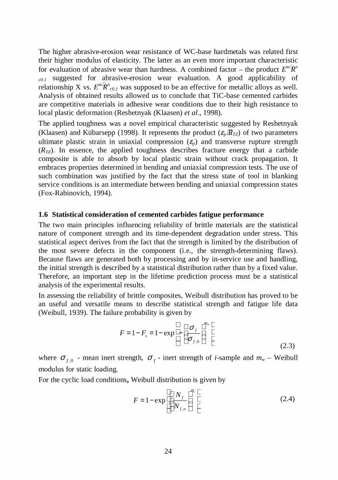
c0.1 was supposed to be an effective for metallic alloys as well.Analysis of obtained results allowed us to conclude that TiC-base cemented carbidesare competitive materials in adhesive wear conditions due to their high resistance tolocal plastic deformation (Reshetnyak (Klaasen) et al., 1998).The applied toughness was a novel empirical characteristic suggested by Reshetnyak(Klaasen) and Kübarsepp (1998). It represents the product (εp⋅RTZ) of two parametersultimate plastic strain in uniaxial compression (εp) and transverse rupture strength(RTZ). In essence, the applied toughness describes fracture energy that a carbidecomposite is able to absorb by local plastic strain without crack propagation. Itembraces properties determined in bending and uniaxial compression tests. The use ofsuch combination was justified by the fact that the stress state of tool in blankingservice conditions is an intermediate between bending and uniaxial compression states(Fox-Rabinovich, 1994).
1.6 Statistical consideration of cemented carbides fatigue performanceThe two main principles influencing reliability of brittle materials are the statisticalnature of component strength and its time-dependent degradation under stress. Thisstatistical aspect derives from the fact that the strength is limited by the distribution ofthe most severe defects in the component (i.e., the strength-determining flaws).Because flaws are generated both by processing and by in-service use and handling,the initial strength is described by a statistical distribution rather than by a fixed value.Therefore, an important step in the lifetime prediction process must be a statisticalanalysis of the experimental results.In assessing the reliability of brittle composites, Weibull distribution has proved to bean useful and versatile means to describe statistical strength and fatigue life data(Weibull, 1939). The failure probability is given by
,0
1 1 expwm
fs
f
F Fσσ
= − = − − (2.3)
where ,0fσ - mean inert strength, fσ - inert strength of i-sample and mw – Weibullmodulus for static loading.For the cyclic load conditions, Weibull distribution is given by
,
1 expcm
f
f o
NF
N
= −
(2.4)

25
where fN - number of cycles to failure, ,f oN - the mean cycle number, mc – Weibullmodulus for cyclic alternating loads. The failure probability F is defined for both casesas
( )0.5iF
n−
=(2.5)
with the sort index i and n the number of specimens (Weibull, 1941).The evaluation of the parameters 0σ , mi, ,f oN , mc (the Weibull statistics) is usuallycarried out using the maximum likelihood method (ENV 843-5:1996). It is the methodof numerical procedure, which leads to more accurate results of the Weibullparameters compared to the evaluation directly out of the Weibull plot by usinggeometric methods or linear regression. There are many theories, which are based onthe Weibull “weakest link” ideas. However, the difference between the predictions anddata obtained for many stress systems is considerable. The number of inner defects ofmaterial is characterized by parameter m, which is also known as homogeneitymodule. Due to the scatter in the failure loads and the inevitable experimental errors, itis always difficult to decide which theory is the most appropriate.Loshak et al. (1981) obtained Weibull parameters data for various loading conditions.Data are presented in Table 1.6. It should be noted that parameters m and 0σ aredifferent for various hard metal grades and testing procedures. It is usually explainedby the differences of inner (bulk) and outer (surface) flaw distribution. Weibullmodulus is related to the rate at which flaws become critical with the stress comparedto the number of flaws that are already critical (Danzer, 1992).
Table 1.6 Weibull statistics obtained for hard metals tested by different loadingschemes (Loshak, 1981)
H6(WC-Co 6%)
H15(WC-Co15%)
H25(WC-Co25%)
Loading schemem 0σ , MPa m 0σ , MPa m 0σ ,
MPaTension 9 1740 9 2390 9 2700Compression 13 6780 15 4900 18 44603 Point-Bending 14 2150 12 2970 11 31004 Point-Bending 10 2260 10 3170 11 3110Cyclic 3Point-Bending 7 1650 8 2060 9 2240
Static Torsion 8 910 8 2050 8 2430The overall objective of incorporating probabilistic analysis into fatigue design is toensure that a low probability exists for a combination of higher than average cyclicstress amplitude and a lower than average fatigue endurance limit (or stress amplitude

26
at a fixed life) to cause failure. In practical design involving the stress-based approachto total fatigue life, however, an endurance limit is first established on the basis ofexperiments conducted on carefully prepared smooth test specimens. This limit is thenlowered by applying modifying factors to account for such effects as surface finish,size effects and constraints, temperature, stress corrosion and numerous unknowneffects (White et al., 1999).The studies concerning Weibull statistics determination summarized by Shleinkofer etal. (1998) showed that hardmetal H12 has a higher value of mean inert strength and allits data in Weibull distribution lay significantly higher as compared with inertstrengths. Therefore, the knowledge of the behaviour of the binder phase is of greatimportance. The results are presented in Table 1.7.
Table 1.7 Weibull statistics of the tests under monotonously increasing and cyclicloads in cantilever bending (Schleinkofer et al., 1998)
Weibull parameterH6
(WC6%Co)H12
(WC12%Co)H6CoNi
(WC6%CoNi)
C16CoNi(Ti(C,N)-
16%CoNi)
Monot. m 39 23 28 26
Monot. 0σ (MPa) 2498 2734 2547 1835
Cyclic m (at
maxσ =1200 MPa) 2.27 1.49 - -
Cyclic Nf,0 , cycles
(at maxσ =1000 MPa)350000 550000 - -
The results from the tests of properties measurement, proper estimation of statisticalparameters of data distribution are usually combined to give a lifetime prediction.However, there is still no way to estimate how statistically significant the lifetimeprediction is. To obtain as much information as possible from the lifetime predictionmodel, it is necessary to estimate the confidence limits associated with the prediction.A special technique is to be used to evaluate the lifetime adequately at whateverconfidence level is desired (White et al., 1999).

27
1.7 Objectives and strategiesWC-base cobalt-bonded hardmetals are the most widely used hardmetals because oftheir excellent strength-wear resistance combination. Among tungsten-free cementedcarbides TiC-based ones, cemented with iron, nickel and molybdenum are utilizedtoday to a minor extent only. However, high hardness, chemical inertness, respectablestrength and fracture toughness, combined with relatively low production costs, maketitanium carbide-base materials one of the widely used wear resistance composites.Recent improvements in materials processing which have resulted in improvementmaterial reliability have created a renewed interest in TiC-base cermets. It isimportant to note that until now there is no complete understanding of the materialbehavior under complex service conditions where all the phases of heterogeneouscemented carbide are subjected to various type of loading.Considering the details of previous research in a field of durability of tungsten-freecemented carbides the obvious need to enlarge the knowledge of materials’ behaviorunder cyclic loading conditions occurs.The objective of the present research was to clarify the fatigue phenomena of majorgrades of cemented carbides and quantify their fatigue characteristics under a constantamplitude cyclic loading. It was important also to connect main mechanicalcharacteristics of materials with their fatigue durability and to assess themicrostructural features of fatigue fracture.To obtain such data the following strategies were used:
• the accelerated fatigue testing procedure for preliminary assessment ofconstitutive behaviour (designed and applied);
• the standard fatigue testing (in three-point bending);• wear tests under adhesive and abrasive-erosion conditions (conducted at
ambient temperature);• the statistical strength and Weibull modulus (calculated and assessed);• the service conditions testing procedure (blanking operation of sheet metal);• the fractography and XRD investigation (of fractured and non-fractured
specimens);• the estimation of fatigue strength of heterogeneous materials containing defects
(Murakami approach).

28
2 EXPERIMENTAL PROGRAMMaterials’ testing to obtain S-N curves is a widespread practice. The need for thisapproach arises from a scatter of fatigue data. The resulting data and curves are widelyavailable in the literature, including various handbooks. An understanding of the basisof these tests is useful effectively to employ their results for engineering purposes. It isknown that collection of fatigue tests data is a time-consuming issue, which results inadditional complexity in evaluation of fatigue strength. Statistical analysis of fatiguedata permits the average S-N curve to be established for various probabilities of failure(Dowling, 1998). But still there are errors of 100% and more are possible. Smallchanges in the composition, design and processing of parts also can have aconsiderable influence on fatigue strength and scatter.
2.1 Materials
1.2.1 Materials characterization
For the investigation of the fatigue behaviour two WC-Co hardmetals and three TiC-base cermets were submitted to static and cyclic loading tests at ambient temperature.High wear resistance combined with high values of strength and toughness is featuresof these materials. They have found especially wide application in producing tools forplastic working of metals, in particular, for sheet metal forming (stamping andblanking dies). The Laboratory of Powder Metallurgy of Tallinn University ofTechnology produced the investigated samples. The set of mechanical properties ofthe TiC-based cermets selected in correspondence with those of WC-based ones wereused in blanking operations: hardness HRA ≥ 87, transverse rupture strength RTZ ≥ 2.1GPa. Mechanical properties and compositions of tested cemented carbides (at ambienttemperature) are given in Table 2.1.
1.2.2 Specimen preparation
All materials investigated were produced through conventional press and sinterpowder metallurgy. According to ASTM B406, the cemented carbide specimens wereprepared to the following dimensions (width ×height × length, respectively) WC-Cogrades 5.0±0.3 × 5.0±0.3 ×19 (mm3), TiC-base - 5.0±0.3 × 5.0±0.3 ×16 (mm3).Specimens were ground to a surface finish of ≈ 15 µm for WC-Co hardmetals and ≈25 µm for TiC-base cermets on four sides. Opposite ground faces were parallel within0.03 mm.Careful grinding techniques were used to prevent various forms of surface cracking(flaws), which are able degrade the measured strength. The four edges of the specimenrepresenting the intersection of the ground faces were chamfered to a maximum of 0.4mm by 45o.

29
Table 2.1. General data and mechanical properties of materials tested
Tested materials H10 H15 T30 T60/8 T70/14
WC content, wt% 90 85 - - -
TiC content, wt% - - 70 60 70
Binder composition andstructure Co Co Ni/Mo
(2:1)Fe/8wt% Nimartensite
Fe/14wt%Niaustenite
Carbide average grain size,dg (µm) 2.0 2.1 2.0 2.2 2.0-2.4
Hardness, HRA 87.5 87.5 88.5 87.5 88.5
Transverse rupture strength,RTZ (GPa) 2.2 2.7 1.6 2.2 2.4
Proof strength RC0.1 (GPa) 3.0 2.3 2.1 2.4 2.2
Young’s modulus, E (GPa) 670 600 395 - 410
Ultimate plastic strain, ε(%) 1.1 1.5 0.8 1.6 1.8
1.2.3 Microstructural features
The microstructures of the tested WC-10wt%Co and WC-15wt%Co hardmetals areshown in Figure 2.1, (a) and (b). The cobalt binder is dark, while tungsten carbidegrains are lighter. The shape of carbide grains is angular. The shape of TiC grains isrounded with no sharp corners. The Microstructure of TiC-base cermets is presented inFigure 2.1 (c) and (d), respectively.
(a) (b)

30
(c) (d)Figure 2.1. Microstructure of the investigated WC-based hardmetals (a) H10, (b)H15 and TiC-based cermets (c) T30 and (d) T70/14
The titanium carbide grains are dark and the binder is lighter. Two different types ofTiC-base cermets were subjected to investigation – (Ni/Mo)-bonded and steel-bonded.Austenitic and martensitic steel was formed during sintering in TiC-steel bondedcermets due to various contents of Ni in the Fe/Ni binder compositions (Table 2.1).
2.2 Accelerated fatigue testingAn accelerated fatigue testing suggested is a procedure [Appendix B, I], based on theidea of evaluating the relationship between stresses and the number of cycles byspecial staircase loading schemes. As a result, the constitutive equations in theexponential form were obtained. Accelerated tests may be used for different structuralmaterials for which the time properties obey the exponential law [Appendix B, I,Eq.1]. The aim was to accelerate the time-consuming fatigue testing and preliminaryto assess the fatigue performance of new materials. On the grounds of the basic theoryof thermal activation processes N. Zhurkov (1965) have received the durability in thefollowing form
KTU
etγσ
ν−
⋅= , (2.1)where ν is the frequency fluctuation factor, which is close by its value to the period offree thermal molecular oscillation (10-23 to 10-12 s). The stress action reduces theenergy of activation from U to U-γσ; where γ is the factor dependent on the activationvolume, i.e., on the structure of the material. The product γσ corresponds to the workof the stress at the molecular bonds in the initial structure; K is Boltzmann’s factor; Tis the absolute temperature (Baily, 1951).At the constant temperature Eq. (2.1) can be used for various materials rewritten asfollows:
ασ−⋅= eAt , (2.2)where A and α are constant factors dependent on the temperature and the mechanicalproperties of the material. The exponential dependence of the durability t on the stress

31
σ is well proved for the materials such as plastics, aluminium alloys, and hardmetals:WC- and TiC-base sintered powder materials. Eq. (2.2) can also be used in the form
ασ−⋅= eAN , (2.3)where N is a number of stress cycles until fracture. To determine material constants Aand α, it is necessary to conduct two series of tests on condition that the values of thestresses σ0 and ∆σ will be equal for both series, but the number of cycles (or time) ineach step for the first series is equal to ∆N1 and for the second series is equal to ∆N2
[Appendix B, I, Fig.1].ResultsThe two constitutive exponential equations were obtained for cemented carbides for apreliminary assessment of their fatigue behaviour.For WC-15wt% Co (H15) alloy:
7 0.00141.954 10N e σ−= ⋅ ⋅ (2.4)And for TiC-30wt%FeNi (T70/14) alloy:
7 0.00091.436 10N e σ−= ⋅ ⋅ (2.5)The important constitutive material constants A and α were calculated using anaccelerated testing approach. The curves obtained from testing can be used asprediction curves for the assessment of lower bands of fatigue limits for these twoparticular cemented carbides.Fatigue constitutive curves obtained from accelerated testing are presented inFigure 2.2.
0 500 1000 15000
5 .10 6
1 .10 7
1.5 .10 7
2 .10 7
Constitutive exponential curves
Sigma max, MPa
Num
ber o
f cyc
les,
N
1.954 10 7⋅ e 0.0014− σ⋅⋅
1.436 10 7⋅ e 0.0009− σ⋅⋅
σ
Figure 2.2. Fatigue constitutive curves for H15 (dash line) and T70/14 (solid line)alloys received by the accelerated testing procedure

32
2.3 Wear testingThere was three major wear testing schemes used: adhesive, abrasive-erosion andsliding wear. Wear tests were complemented by functional tests – service conditionsdurability tests [Appendix B, III].A special method was elaborated for adhesive wear testing. The essence of the methodis turning of mild steel (170HV) at low cutting speed, in which adhesion phenomenapredominate. The wear rate was determined as the height h of the wear land at the tool(specimen) tip after a specific length of the cutting path L. The adhesive wearresistance was determined as the length of the cutting path when the height of the wearland achieved the critical value of 1 mm. The critical height of the wear landcorresponded to the onset of the accelerated wear [Appendix B, III, Fig.3]. Confidenceinterval of the wear resistance did not exceed 10% when the number of test specimenswas at least three.Abrasive-erosion tests were conducted on a centrifugal accelerator [Appendix B, III].The conditions were as follows: abrasive-quartz sand with particle size 0.1÷0.2 mm,jet velocity 80 m⋅s-1 and attack angle 30°. The abrasive-erosion rate was determined asspecific volume wear (mm3) corresponding to 1 kg of abrasive. The relative wearresistance X was determined as the ratio of the wear rate of the studied alloy. Four testspecimens were analysed and the wear rate confidence interval 10 % with theprobability factor of 95 %.Sliding wear tests were performed in accordance with the ASTM standard B611-85,without abrasive at a loading 40N and wear path length equal to 4000m. Thevolumetric wear rate was calculated as ρmV ∆=∆ , where m∆ is the average massloss and ρ is the density of the alloy.
ResultsIn terms of abrasive-erosion wear resistance TiC-base cermets, as expected, have aconsiderable disadvantage over the WC-base hardmetal. The results of theexperimental investigation demonstrate the superiority of titanium carbide basecermets over the WC-base hardmetal from point of view of adhesive wear resistancepoint of view. This confirms that the adhesive wear resistance of carbide compositesdepends primarily on the properties of the binder and less on those of the carbidephase. In its turn, the abrasive wear resistance depends, in contrast to adhesive wearprocesses, on the properties of carbide phase: its strength and rigidity. In general, itmay be stated that between the blanking performance of materials investigated andtheir adhesive wear resistance a fair correlation exists [Appendix B, III, Fig.4]. Thenature of failure and the fractured surfaces in adhesion testing and in the servicecondition testing were similar [Appendix B, III, Fig. 5]. After removal of the binder,the worn areas of the subsurface act as failure initiating stress concentrators inducingacceleration of wear process. In the last step, the removed carbide particles act asabrasive particles. The investigation of worn surfaces near the cutting edges ofblanking tools by SEM exposed some differences in the micro-mechanism of wear

33
[Appendix B, III, Fig 7 and 8]. The formation of the local microfailure results in themicrochipping of cutting edges during blanking. Microchipping of cutting edgescauses an increase in shearing forces (Mode II cracking), which results in theacceleration of the side wear.
2.4 Fatigue testingIn order to evaluate the fatigue data and the damage processes under cyclic loadconditions the behaviour of materials under monotonic loads has to be determined.The result obtained from monotonic testing was an inert bending strength in three-point bending loading (RTZ0), which was further used for cyclic stress levels selectionin cyclic loading [Appendix A, Fig.A1]. Twelve specimens of each grade weresubjected to monotonic loading. The same three-point bending procedure was used forfatigue data accumulation. The procedure used is complies with ISO 3327 (ASTMB406). The investigations were carried out on the dynamic and fatigue test systemINSTRON 8516. The test apparatus was automatically controlled by a Windowsmicrocomputer-based system. Data processing and registering was made with the Maxv4.2 software.The controlled parameters were: 1) cyclic loading parameters (loading scheme withloading amplitudes), 2) the loading frequency and 3) the displacement of the zeroposition of specimen. The fatigue limits were defined for lifetimes as long as 107
cycles. The schematic representation of the loading history of mechanical tests isshown in Figure 2.3. The frequencies of cyclic loading were equal to 1 and 22 Hz. Thevelocity of the load applied did not exceed 1 kNs-1. The fracture occurred around themiddle of the specimen within one third of the span between the supporting cylinderson the tension side of the specimen. The maximum applied cyclic stress was equal to90% of RTZ0. The stress ratio R was equal to 0 for all cyclic tests.
Figure 2.3. Schematic representation of the load history in bending: undermonotonic (a) and cyclic (b)
ResultsThe resistance of materials tested to the damage processes under cyclic loading ismuch lower than under static monotonic loading. The different slopes of theregression scatter bounds express the different fatigue sensitivity of the materials. It is

34
obvious that the grades with lower fatigue sensitivity are more suitable for applicationunder service conditions where the cyclic loading takes place. Higher slopes in theplots indicate a higher degree of accumulation of damage during the cyclic loading.Thus, the cermet T70/14 is superior in its behaviour at a higher number of cycles. Thefatigue testing data are presented in Figure A4 in Appendix A.The estimated endurance limits, Weibull statistics of monotonic and cyclic loadinghistories are presented in Table 2.1.
Table 2.1. Endurance limits and Weibull parameters for monotonic and cyclicloading
GradeEndurance
limit Se,(GPa)
Weibull parameter formonotonic loading (MLE) m0
and Sb0 (MPa)
Weibull parameters for cyclicloading mc and Nf0
H10 1.23 18.7 2.3 0.42 ≈ 440000H15 1.56 14.5 2.7 0.81 ≈ 560000T60/8 0.62 10.2 2.2 0.47 ≈ 320000T70/14 1.41 13.6 2.4 0.64 ≈ 670000T30 0.51* 10.8 1.8 0.37* ≈ 240000**on the basic of 105 cyclesThe evaluations of Weibull parameters were carried out using maximum likelihoodestimation (MLE) method. The determined parameters are equated in accordance withDIN 51110. Considerable scatter of data for hardmetal H10 is explained by the lowercontent of binder, which causes the higher degree of heterogeneity of the composite.Wöhler plots Smax vs. LogN (number of cycles until failure) is shown in Figure A1[Appendix A]. The fatigue strength of carbide composites varies in proportion to theirtoughness characteristics. It has been emphasized that the fatigue strength-appliedtoughness relation is more accurate than that of fatigue strength-stress intensity factorone [Appendix B, IV, Figs.3 and 4].
Table 2.2. Threshold characteristics of the materials investigatedThreshold stress
intensity factor Kth,MPa⋅m-1/2
Endurance limit Se,GPa
Grade Fracture toughnessKIC, MPa⋅m-1/2
Previouswork
Presentwork
Previouswork
Presentwork
H10 14.0 6.8 8.9 1.3 1.23H15 17.0 6.3 9.7 1.5 1.56T30 9.5 - 6.4 0.4* 0.5*
T70/14 18.0 - 11.9 1.2 1.41*on the basis of 105 cycles

35
Improvement of fatigue strength by a factor 4 (low cyclic fatigue strength) and 6(endurance limit) results from the increase of applied toughness TZp R⋅ε by a factor ofthe same rate – 5. At the same time, stress intensity factor KIC is 1.8 times only.Threshold characteristics: endurance limit and threshold stress intensity factors(quantified by Eq.1.2) are given in Table 2.2.
2.5 Durability testing in blankingThe durability tests were carried out as service conditions (functional) ones, blankinggrooves into electro-technical sheet steel with hardness 150HV, proof stress 1.6 GPa,and ultimate strength 3.2 GPa and sheet thickness 0.5 mm. The 3-position die wasreinforced with three different cemented carbides to be investigated. Die was mountedon an automatic mechanical press [Appendix B, III, V, Fig.1]. The blankingperformance of hardmetals was evaluated by the measure of side wear ∆D after anintermediate service time (5⋅105 strokes) corresponded to the time between twoconsecutive preventive sharpening used in the exploitation of blanking dies. The sidewear measurement was taken by means of the measuring machine WMM500 inconstant environmental conditions as an average of 4-6 measurements.ResultsThe results of functional tests are shown in Figure 3 [Appendix B, III] as wearcontours. During testing of the die, neither fracture nor brittle macrochipping ofcutting edges was detected. Cutting edges became blunt as a result of uniform wear.The wear contour and the side wear data for the die tested demonstrated the obvioussuperiority of TiC base cermets over conventional hardmetal H15 commonly used inblanking operations. Figure 4 [Appendix B, III, V] shows the blanking performance ofcarbide composites opposed to their response as inserts in erosion, sliding andadhesive wear conditions.
2.6 Fatigue and bending strength: related fractographyThe two main theories of hardmetal microstructure exist currently. Discussions aboutthe predominance of one or another are held at present. Gurland (1963) suggested thathard carbide grains (WC) are introduced into the metallic matrix and completelyisolated by binder (cobalt) from each other. This is so called matrix structure. Thesesuggestions are made on the basis of WC grains excellent wetability and noticeableplasticity of WC-Co compositions with low cobalt content. The existence of carbideskeleton for the alloys with low binder content (lower than 10 %) is not denied. Also,agglomerates of joint carbide grains can be present in hardmetals with a high volumeof cobalt.The second suggestion is the existence of continuous carbide skeleton structure.Carbide frame is the continuous structure of connected (coalescent) WC grains’(content of tungsten carbide from 50wt% and higher). Slip bands found in the carbidegrains during deformation proved this theory. In matrix structure reinforcement

36
proceeded by blocking of binder plastic deformation with carbide grains (Kreimer,1971). The continuous carbide skeleton can be destroyed only by the fracture of abinder (possibility of binder shift is limited by tough carbide skeleton).The dominant features of fatigue phenomena comprise not only macro-scale changesin material structure but also cover its local (micro-scale) plastic strains. In mostprevious studies (Sarin et al., 1974; Brooks, 1982; Loshak, 1984 etc.) the cobalt binderof WC-Co alloys has been considered as f.c.c.-metal, which in the as-sinteredconditions can also deform by transforming to h.c.p. This initially gives the binder theability to deform in full compatibility with the carbide skeleton. Ultimately thepartially transformed binder is unable to fulfill the compatibility requirements andloses its ability to impede crack propagation. Since the influence of carbide grains onthe bulk material fracture (monotonic and cyclic) as a whole is still undefined, thequestion concerning their deformation and fracture behavior arises to create anunambiguous conception about the composite constitutive behaviour. The study of thefine structure of both WC and TiC carbide phase were carried out by XRD-techniquemainly used for measuring crystal lattice parameters, residual stresses and crystallitesizes. It was assumed that during monotonic and cyclic loading certain changes ofthese characteristics took place.After mechanical testing selected specimens were taken and subjected to a detailedfractographic examination by scanning electron microscopy (SEM) and X-raydiffraction.All scanning electron microscope micrographs [Appendix A, Figs.A5-A10] weremade on JEOL JSM840a apparatus with following specifications:
• KV range 0.5 to 40• magnification range 10X to 300000X• filament type - tungsten• resolution – 3.5 Å
The fine structure of grain is characterized by the dispersity of its crystallites, whichintroduced as regions of coherent dispersion of X-ray. The amount of dislocations andvacancies in lattice (microdistortions) is also a characteristic feature of crystallite.Plastic strain as the onset of fracture induces changes in grain structure by increase indispersity of crystallites (their fragmentation) and by origin of dislocations. Thesechanges result in alteration of the crystallite X-ray diffraction pattern: an increase inwidth full-width half-maximum (FWHM) of curve, characterizing the beam signal anddecrease of its peak intensity.The XRD-studies of carbide phase were carried out by the XR- difractometer BrooksD5005. Two major alloys T70/14 and H15 were subjected to X-ray investigations.Specimens used for fatigue testing with configurations 5 x 5 x 16 mm3 (T70/14) and 5x 5 x 19 (H15) firstly were ground and then annealed in vacuum at 900oC to removethe residual stresses after grinding. Further, they were subjected for cyclic andmonotonic loading at ambient temperature.The XRD analysis layout was next:
• after grinding (standard or referent),

37
• after annealing,• after fatigue testing at 80% of Se (endurance limit) on the base of 105 cycles
without fracture of a specimen,• after fatigue testing at Se until fracture of a specimen,• after monotonic testing in bending until fracture (to reach the RTZ).
The XRD pattern of fractured specimen presented in Figure 2.4 were analysed a) at themaximum failure stress region (area 1) b) at the stress level of 0,8Se (area 2).
Figure 2.4. Representation of sample areas analysed by X-Ray diffractionResultsSpecial attention was paid to determine fracture micromechanisms associated with thedifferent loading conditions studied.First of all, an extended fractographic analysis indicated subsurface processingheterogeneities: pores, abnormally large carbides, binderless carbide clusters anddiscrete agglomerates as usual fracture initiation sites in the bending strength tests.Dimpled ductile rupture in the metallic binder interdispersed with cleavage andintergranular fracture of the carbides were the relevant fractographic featuresdiscerned in the surfaces of broken specimens, in agreement with previousinvestigation on this subject (Llanes et al., 2000). Failure of the hard metals andcermets occurs under cyclic loading at considerably lower stress levels compared withthe failure under monotonic loading. Therefore, different damage processes anddamage mechanisms in the two types of loading cause this. Three fracture zones canbe seen at the fracture surfaces of the specimen: a) slightly rough zone of stable crackpropagation with the fracture initiation point (source of the crack); b) the zone of crackintensive propagation with coarse rough surface of fan-shape profile; c) zone of finalfracture. In the first zone flaw propagates in a stable mode due to loads. The initialgrowth rate is low. The crack growth rate accelerates with time, but the crack remains“stable”. In this case rate-controlling factors are microstructure and applied load. Thefracture surface micrographs of H10 are presented in Figure A7 [Appendix A]. Thedamage processes under cyclic loads are assumed to occur only in the ductile binderphase. But numerous fractured grains in the structures of both investigated hardmetalscan be seen in Figures A7 and A8 [Appendix A]. This fact proves the assumptions thatelastic-plastic deformation and development of slip bands in WC grains can definitelyoccur under cyclic loading conditions. The phase transformation and crack tipshielding by ligaments observed by Shleinkofer et al., seems to be the main reasonwhy the hardmetals show a stronger fatigue effect than the cermets in the life timedepending on the stress amplitudes in the cyclic loading.
F
12
3
1.5

38
The fracture surfaces of T70/14 cermet have a mixed character. SEM micrographsshow carbide grain cleavage (crack path C), the location of the crack path in theductile binder phase (crack path B) and fracture of the phase boundary binder/ceramic(crack path B/C) Plastic deformation of thin binder layer between TiC grains is notdifficult to see. But TiC grain elastic-plastic deformation traces should be examined bymeans of the XRD analysis. Brittle striations of T70/14 are characteristic feature ofcrack advancing with cycling. They are perpendicular, or almost so, to the direction tothe crack propagation. Plastic striations can be observed on the little binder areas also.Plastic fracture features are visible in Figure A6 [Appendix A] as small dimples ofbinder phase in the lower left corner of the micrograph. As both ductile and brittlefracture features are seen, it can be assumed that under cyclic loading conditions TiCbase with (Fe/Ni)-binder cermet work in the ductile-brittle transition interval.SEM images of blanking tools are presented in Figures A9 and A10 [Appendix A].Punches were examined after 500000 work cycles. Uniform blanking tool wear isdominant for all tested materials, but certain features of local fracture can be seen onthe edges of the tested materials. In all materials, wear starts with binder extrusion-intrusion process. After adhesion between blanking tool and formed material surfacetensile and shear stresses appear. As a result, influence areas of bare carbide grains canalso be observed in Figures A9 and A10 [Appendix A]. In the final stage of thatprocess, carbide grains with or without binder are extruded from the surface of theblanking tool. These areas are similar in TiC base cermet blanking tool. From Figure 9[Appendix A] it can be noticed that edge chipping is characteristic feature of the wearprocess of H15 blanking dies. Cutting edges are very rough and filled with particlesseparated from the formed metal. On the contrary, cutting edges of T70/14 cermet aresmooth and clear. There are no traces of large edge chipping processes. But smallfatigue cracks are visible in the vicinity of the cutting edge. This analysis completelycorrelates with the numerical data obtained from both fatigue and adhesive weartesting. Wear of cutting edges of T70/14 female die is almost three times lower thanthat of H15 (4 µm and 9 µm respectively). Wear of cutting edge of T70/14 female dieis approximately 2.5 times lower than that of H15 (3 µm and 7.5 µm respectively).Measurements were made on the depth of 0.2 mm from the upper plane of female dieand lower plane of male die. On the basis of the examination it can be stated thatT70714 cermet can be accepted as a blanking tool material. It is evident fact that theadhesive wear and fatigue performance properties of this material are better than thoseof traditional H15 hardmetal.XRD examination showed that after grinding remarkable changes in fine structure ofboth WC and TiC cermets took place [Appendix A, Fig.A11]. Fatigue tests conductedat maximum stress level 80% of endurance limit without sample fracture (on the basisof 105 numbers of cycles) did not introduce any changes in X-ray patterns of materialsmicrostructure. The fatigue testing until fracture of specimen at the stress level of theendurance limit showed remarkable decrease of peak intensity of X-ray signal for WCphase. While changes of fine structure of TiC phase were obviously less (area 1)compared with WC one [Appendix A, Figure A12]. Monotonic testing until specimenfailure resulted in sharper decrease of X-ray peak intensity (area 2) for both TiC and

39
WC phases. Plastic deformation of carbide phase occurs predominantly at the stresslevel close to material transverse rupture strength - the X-ray pattern characteristicsconfirm this statement [Appendix A, Figure A13].

40
3 STATISTICAL ASPECTS OF FATIGUE PERFORMANCE ANDENDURANCE LIMIT PREDICTION
3.1 Statistical strength, testing procedures and Weibull modulusTo determine failure probability of heterogeneous brittle materials such as cementedcarbides in varying stress fields, there are many theories, which are based on theWeibull “weakest-link” ideas. The difference between the Weibull statistics arisesfrom the different stress states of the material during testing. The attempt to definethese differences showed the evident influence of the test method and threshold stresson the Weibull modulus [Appendix B, II, Eqs.13, 16, 20]. Tests were carried out formonotonic loads with the further analysis of the test data. The cumulative probabilitythat brittle material (with the fracture toughness below 20 MPa⋅m-1/2) fails duringstressing in a uniform tension up to a stress σ, F(σ), is given by:
( )0
( ) 1 exp 1 expm
F Sσσ σσ
= − − = − −
, (3.1)
where 0σ is a normalizing parameter and m is a constant known as the Weibullmodulus. It is frequently assumed that the Weibull modulus has no physicalsignificance. Danzer et al. (1992) have derived an alternative formula which showsthat the cumulative failure probability F(σ) could be given by
[ ]( ) 1 exp ( )F Sσ σ= − − , (3.2)
where S(σ) is the mean number of flaws (the presence of these flaws causes reductionsin fracture toughness and strength) in a specimen during loading to σ. A critical ordominant flaw is one, which, satisfied some fracture criterion, e.g. KI>KIC, could bethe simplest criterion of such kind. It should be noted that Weibull and Danzer’sapproach could not be used to describe: a) fracture in materials, which exhibit R-curvebehaviour or b) fracture in stabilizing stress field. It was assumed, therefore, that inboth cases the initial and crack growth (the moment of fracture occurrence) flawdistributions were different. Consequently, the weakest link approach cannot be useddirectly to describe cracking in this case. To make the weakest link approach reliableonly surface-cracking flaws were considered [Appendix B, II, Eq.9].ResultsIn theoretical considerations, the Weibull modulus calculations in tension, three-pointbending and four-point bending tests were conducted. Three plots of Weibull modulusvs. ratio maximum stress (σn) to the lower limit of maximum stress (σL) were obtainedand presented in paper II [Appendix B, Fig.1]. The greatest increases in the Weibullmodulus were expected for the three-point bending test and the smallest changes forthe tension test. A confirmation of these predictions was provided by experimentalresults of Loshak (1984), Torres et al. (2002) and Preis (2000).
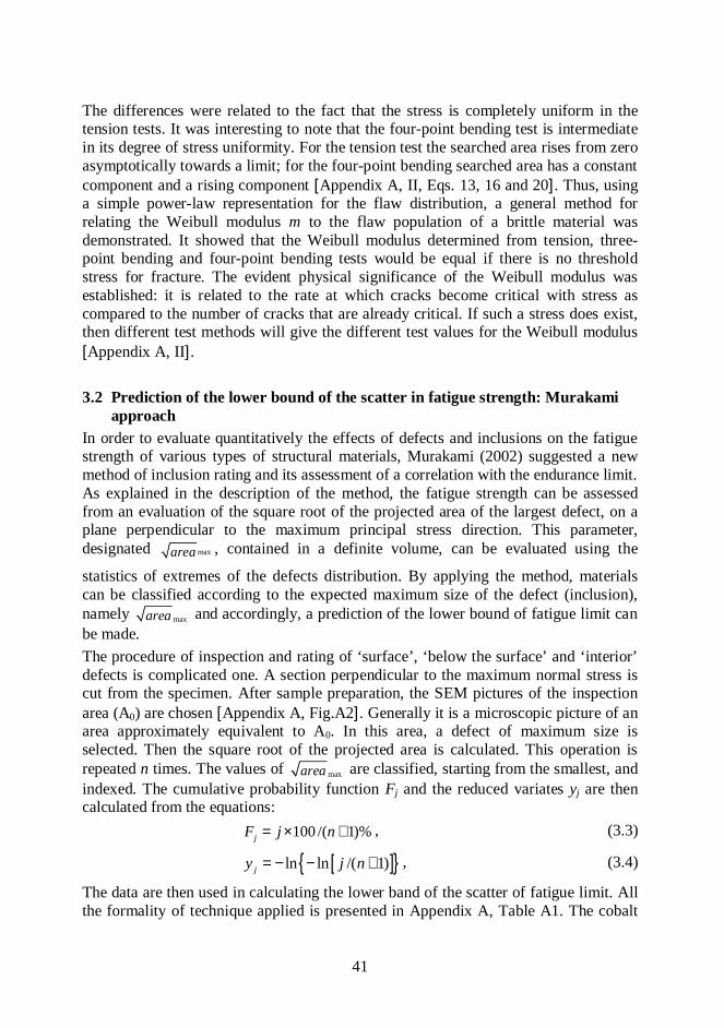
41
The differences were related to the fact that the stress is completely uniform in thetension tests. It was interesting to note that the four-point bending test is intermediatein its degree of stress uniformity. For the tension test the searched area rises from zeroasymptotically towards a limit; for the four-point bending searched area has a constantcomponent and a rising component [Appendix A, II, Eqs. 13, 16 and 20]. Thus, usinga simple power-law representation for the flaw distribution, a general method forrelating the Weibull modulus m to the flaw population of a brittle material wasdemonstrated. It showed that the Weibull modulus determined from tension, three-point bending and four-point bending tests would be equal if there is no thresholdstress for fracture. The evident physical significance of the Weibull modulus wasestablished: it is related to the rate at which cracks become critical with stress ascompared to the number of cracks that are already critical. If such a stress does exist,then different test methods will give the different test values for the Weibull modulus[Appendix A, II].
3.2 Prediction of the lower bound of the scatter in fatigue strength: Murakamiapproach
In order to evaluate quantitatively the effects of defects and inclusions on the fatiguestrength of various types of structural materials, Murakami (2002) suggested a newmethod of inclusion rating and its assessment of a correlation with the endurance limit.As explained in the description of the method, the fatigue strength can be assessedfrom an evaluation of the square root of the projected area of the largest defect, on aplane perpendicular to the maximum principal stress direction. This parameter,designated maxarea , contained in a definite volume, can be evaluated using the
statistics of extremes of the defects distribution. By applying the method, materialscan be classified according to the expected maximum size of the defect (inclusion),namely maxarea and accordingly, a prediction of the lower bound of fatigue limit canbe made.The procedure of inspection and rating of ‘surface’, ‘below the surface’ and ‘interior’defects is complicated one. A section perpendicular to the maximum normal stress iscut from the specimen. After sample preparation, the SEM pictures of the inspectionarea (A0) are chosen [Appendix A, Fig.A2]. Generally it is a microscopic picture of anarea approximately equivalent to A0. In this area, a defect of maximum size isselected. Then the square root of the projected area is calculated. This operation isrepeated n times. The values of maxarea are classified, starting from the smallest, andindexed. The cumulative probability function Fj and the reduced variates yj are thencalculated from the equations:
100 /( 1)%jF j n= × + , (3.3)
[ ]{ }ln ln /( 1)jy j n= − − + , (3.4)
The data are then used in calculating the lower band of the scatter of fatigue limit. Allthe formality of technique applied is presented in Appendix A, Table A1. The cobalt

42
binder Vicker’s hardness was measured for the final calculation of lower bound ofendurance limit. In this prediction procedure only one WC-base hardmetal wasexamined. Its defect areas were measured by means of transporting the SEM imagesof samples into AutoCAD interface, and resulted in the calculation and rating of thesize of the defect areas [Appendix A, Fig.A3].
ResultsThe possibility of using maxarea as the geometrical parameter was suggested in theprediction of the fatigue strength of H15 hardmetal presented. As was describedabove, if one accepts that the fatigue limit of a material containing small defects orcracks is the threshold condition for non-propagating cracks, then it is rational toconsider the most appropriate material parameter for describing the thresholdbehaviour. From the trends of the correlation of HV with the stress intensity factor (formost metallic bulk materials) it was assumed that this parameter of Co-binder of WC-Co composite might suit for fatigue strength assessment. In addition, the adhesionwear of carbide composite is controlled, first of all, by properties of its binder(intrusion-extrusion mechanism of adhesion). The results of equating the lower bandof scatter of fatigue strength (Se ≈ 590 MPa) on the basis of Vickers hardness andgeometric parameter maxarea showed its excellent convergence with experimentaldata received from both the testing procedure of standard fatigue tests (Se,min ≈ 720MPa) and accelerated fatigue ones (Se. ≈ 500 MPa).

43
CONCLUSIONS
1. In the study carried out it was shown that the fatigue performance of cementedcarbides has to be taken into account if an evaluation of reliability is required.
2. The dominant feature of fatigue phenomenon of heterogeneous materials is thatthe onset of failure starts and takes place mainly in the binder phase.
3. During cyclic loading the cobalt binder phase of WC-base alloy deforms bytransformation from f.c.c to h.c.p. crystal structure with ligament zone formation.As a result, this transformation decreases the ability of binder to impede crackpropagation. On the other hand, the most part of carbide phase is deformed in theimmediate region of fracture stress with high level of plastic strain energyaccumulated. Consequently, a higher magnitude of transverse rupture strength(RTZ) is typical of WC-Co composite.
4. In its turn, the lower fatigue sensitivity of TiC-base cermet can be explained bythe absence of such a Fe/Ni-binder phase transformation as of cobalt binder. Atthe same time, more brittle TiC-phase gives the lower value of bulk material RTZ.
5. Better blanking performance of TiC-base cermet with steel binder can beattributed to its lower fatigue sensitivity. It was also shown that the fatiguesensitivity of cermets is controlled by the plasticity of bulk materials.
6. A recent study has shown that the adhesive wear fracture of cemented carbidesstarts like fatigue does – predominantly in the binder phase (extrusion-intrusionmechanism) and in contrast to abrasive erosion and sliding wear. In this case, theproperties of binder (strength and adhesive interaction) are of more interest thanthose of the carbide phase. Reasonable correlation between the blankingperformance and adhesive wear resistance, and similarity in the surface failuremorphology was found. Local microfailure zones result in the microchipping ofcutting edges during blanking. Microchipping in its turn causes an increase inshear stresses, resulting in the acceleration of tool wear.
7. The X-ray examinations stated that the plastic strain – onset of failure of WC-and TiC-base cemented carbides during cyclic loading starts and takes placemainly in the binder phase. The carbide phases do not undergo any plastic strainduring cyclic loading at the stress levels below the fracture stress. Theconsiderable plastic strain of carbide phase under cyclic load conditions occurspredominantly at the stress level close to material fracture stress. The critical

44
plastic strain of WC-phase of WC-15wt%Co composition exceeds that of TiC-one. The tungsten carbide phase is more plastic compared to the TiC one.
8. The new technique developed by Murakami (2002) for the prediction of thelower bound of endurance limit of WC-Co hardmetal was applied. It wasaccepted that the endurance limit of a material containing small defects,inclusions or cracks is the threshold condition for non-propagating cracks. TheVicker’s hardness of cobalt binder (as main responsible for the fracturecharacteristic) and geometrical parameter of maximum area of structural defectwere assumed to be the basis of such calculations. The results of this procedureshowed excellent convergence with experimental data received from both testingprocedure of standard fatigue tests and accelerated fatigue ones.

45
REFERENCES
• Almond, E., and Roebuck, B. (1981). Fatigue crack growth in WC-Co. MetalsTechnology. 2: 83-85.
• Baily, R. (1951). Creep relationships and their application to pipes, tubes andcylindrical parts under internal pressure. Journal of European Ceramic Society.London. 36-47
• Brookes, K., (1982) World dictionary and handbook of hardmetals and hardmaterials. 5th ed. London: International Carbide Data
• Brooks, K. (1996). World dictionary and handbook of hardmetals and hardmaterials. 6th ed. London: International Carbide Data.
• Danzer, R (1992). Ageneral strength distribution function for brittle materials.Journal of European Ceramic Society. 10: 461-472
• DIN 51110 Maximum Likelihood Estimation of Weibull Modulus static,monotonic and cyclic loading. Brittle materials.
• Dowling, N. (1998). Mechanical behaviour of materials.New Jersey. 1999• Exner, H. and Walter, A. and Pabst, R. (1974). Zur ermittlung und darstellung
der fehlerverteilungen von spröden werkstoffen. Materials Science andEngineering. 8: 925-934.
• Fox-Rabinovich, G. and Kovalev, A. (1994). Characteristic features of blankingdie wear with consideration for the change in composition, structure andproperties of contact surfaces. Wear. 189: 25-31.
• Fry, P. and Garret, G. (1983). The inter-relation of microstructure, toughnessand fatigue crack growth in WC-co hardmetals. Proceedings of theInternational Conference on Speciality Steels and Hard Materials. London.Pergamon. 375-381.
• Gurland J. (1963) The fracture strength of sintered WC-Co alloys in relation tocomposition and particle spacing.- Transactions of Metallurgical Society.227.10. 1063-1071.
• Hiroshe, Y., Boo, M., Matsuoka, H. and Park, Y. (1997). Influence of stressratio and WC grain size on fatigue crack growth characteristics of WC-Cocemented carbides. Journal of Society of Materials Science in Japan. 46: 1402-1409
• Ishihara, S., Goshima, T., Yoshimoto, T. and Sabu, T. (1999) On fatiguelifetimes and crack growth behaviour of cemented carbides. Fatigue’99.Proceedings of the 7th International Fatigue Congress. Beijing. 1811-1816.
• ISO 3327 (ASTM B406) Transverse Rupture Strength Determination:Cemented Carbides.
• Kenny, P. (1971) The application of fracture mechanics to cemented carbides.Powder Metallurgy. 14: 22-38.

46
• Knee, N. and Plumbridge, W. (1984). The influence of microstructure and stressratio on fatigue crack growth in WC-Co hardmetals. Proceedings of the 6th
International Conference on Fracture. New Delhi. 2685- 2692.• Kreimer, H. (1971). Strength of hardmetals. Moscow: Metallurgiya (in
Russian).• Kursawe, S., Pott, Ph., Sockel, H. G., Heinrich, W., Wolf, M. (2001). On the
influence of binder content and binder composition on the mechanicalproperties of hardmetals. International Journal of Refractory Metals & HardMetals. 19: 335-340.
• Lawn, B. (1993). Fracture of brittle solids. 2nd edition. Cambridge. CambridgeUniversity Press.
• Llanes, L. Torres, Y., Anglada. (2002). On the fatigue crack growth behavior ofWC-Co cemented carbides: kinetics description, microstructural effects andfatigue sensitivity. Acta Materialia. 50: 2381-2393.
• Llanes. L., Torres, Y., Casas, B., Casellas, D., Marimon, F., Roure, F., andAnglada M. (2001). Fracture behaviour of cemented carbides: a fracturemechanics analysis. Proceedings of the 13th European Conference of Fracture,Fracture Mechanics: Applications and Chalanges. San Sebastian: Elsiver. ECF13 on CD-ROM.
• Loshak, M. (1984). Strength and durability of hardmetals. Kiev: NaukovaDumka (in Russian).
• Murakami, Y. (2002) Fatigue of metals. London. Elsiver.• Preis, I. (2000). Assessment of fatigue characteristics of cemented carbides.
Thesis for the degree of Master of Science in Engineering. Tallinn.• Reshetnyak, H. and Kübarsepp, J. (1997). Structure sensitivity of wear
resistance of hardmetals. International Journal of Refractory Metals & HardMaterials. 15: 89-98.
• Reshetnyak, H. and Kübarsepp, J. (1998). Resistance of hardmetals to fracture.Powder Metallurgy. 41: 211-216.
• Sarin, V. (1974). Metall Science. 9: 472-476.• Shleinkofer, U., Sockel H., Görting, K. and Heinrich, W. (1996). Fatigue of
hardmetals and cermets. Materials Science and Engineering. A, 209: 313-317.• Shleinkofer, U., Sockel H., Görting, K. and Heinrich, W. (1997). Fatigue of
hardmetals and cermets – new results anf better understanding. InternationalJournal of Refractory Metals and Hard Materials. 15: 103-112.
• Shleinkofer, U., Sockel H., Görting, K. and Heinrich, W. (1996).Microstructural processes during subcritical crack growth in hard metals andcermets under cyclic loads. Materials Science and Engineering. A, 209: 103-110.
• Shleinkofer, U., Sockel H., Schlund, P., Görting, K. and Heinrich, W. (1995).Behaviour of hardmetals and cermets under cyclic mechanical loads. MaterialsScience and Engineering. A, 194:1-8.

47
• Sigl, L. and Exner, H. (1987). Experimental study of the mechanics of fracturein WC-Co alloys. Metall Transactions. 18. 1299-1308.
• Sigl, L. and Fishmeister, H. (1988) On the fracture toughness of cementedcarbides. Acta Metallurgia. 36: 887-897.
• Suresh, S. (1991). Fatigue of materials. Cambridge: Cambridge UniversityPress
• Torres, Y., Anglada, M. and Llanes, L. (2001). Fatigue mechanics of WC-Cocemented carbides. International Journal of Refractory Metals & HardMaterials. 19: 341-348.
• Torres, Y., Casellas, D., Anglada M. and Llanes L. (2000). Fracture toughnessevaluation of hardmetals: influence of testing procedure. International Journalof Refractory Metals and Hard Materials. 19: 27-34.
• Weibull, W. (1941). A statistical distribution function of wide application.Journal of Applied Mechanics. 18: 293-297
• Zhurkov, S. (1965). Kinetik concept og the sthrength of solids. InternationalJournal of Fracture Mechanics.4:66-71

48
SYMBOLS AND ABBREVIATIONSSymbolsdWC – mean tungsten carbide grain sizeE – Young’s modulusF – probability of failure
maxarea - maximum size of the defect area(Murakami’s parameter) – Poisson’s ratio – applied stress (nominal)0 – normalized parameter of inert strength (Weibull statistics)max – maximum applied stressmin – minimum applied stressm - mean applied stress
– applied stress rangeth – applied threshold stress (range)
RTZ – transverse rupture strengtha – stress amplitude
RCM – compressive strengthRC0.1 – proof stress in compression
a – stress amplitudem – mean stressf – fatigue limit (strength) - shear stress
K – stress-intensity factorKc – fracture toughnessKIc – plane-strain fracture toughnessKth – threshold stress intensity factorKf – fatigue limit stress intensity factor
Kth – range of threshold stress intensity factorm – Weibull modulusm0 – Weibull modulus of monotonic testingmc – Weibull modulus of cyclic testingN – number of elapsed stress cyclesNf – fatigue life (cycles)R – stress ratio

49
co – binder thickness, of cobalt in WC-Co cemented carbidesCWC – carbide contiguity, of tungsten carbide skeleton in WC-Co cemented carbidesVco – volume of cobalt binder
p – ultimate plastic strain - density
Se – endurance (fatigue limit)Smax – maximum nominal stressSb - inert bending strength,S (σ) – mean number of surface flawsAbbreviationsASTM – American Standards of Testing MethodsFCG – Fatigue Crack GrowthHRA – Rockwell hardness numberHV – Vickers hardness numberSEM – Scanning Electron MicroscopeISO – International Standardization OrganizationDIN – German industry standard (Deutsche Industrie Norm)

50
APPENDIX A

51
Figure A1. Wöhler plots for TiC-base and WC-base hardmetals.
Wöhler plot for T30 cermet
0
0,4
0,8
1,2
0 1 2 3 4 5 6
logN
Sm
ax, G
Pa
T30 with slope 0,11 on thebase of 10e5 cycles
Wöhler plots for T60/8 and T70/14 cermets
0
1
2
3
0 1 2 3 4 5 6 7 8
LogN
Sm
ax, G
Pa
T60/8 with slope 0,149
T70/14 with slope 0,098
Wöhler plots for H10 and H15 hardmetals
0
1
2
3
0 1 2 3 4 5 6 7 8
LogN
Sm
ax, G
Pa
H10 with slope 0,146H15 with slope 0,109

52
Figure A2. Samples of SEM images of the inspection area for hardmetal H15
Figure A3. Images of area of defects imported to AutoCAD for the defect areacalculations

Table A1. Defects inspection items
Inspection items
Material: H15, WC- 15wt %CoControl section: Transverse to normal stressStandard inspection area: 0.134 mm2
Number of inspections: n=99
Maximum defect distribution
max 33.006 55,665area y= +Test area: A (mm2)Return period: T = A/A0
Cum. Distr. Func. 100 /( 1)%jF j n= × +
Reduced variate [ ]{ }ln ln /( 1)jy j n= − − +

Table A1. Defects inspection items (continue)
Prediction of maxarea
A (mm2) T maxarea (µm)1 7.44 119.552
10 74.41 197.682100 744.01 273.883
Prediction of lower bound of the scatter in fatigue strengthCo – binder HV = 174
( ) ( )1 61.43 120 /e VS H area= +
for surface defects MPa( ) ( )1 6
1.41 120 /e VS H area= +
for defects just below the surface,MPa
( ) ( )1 61.56 120 /e VS H area= +
for interior defects, MPa
1 598eS = 1 590eS = 1 652eS =
10 550eS = 10 542eS = 10 600eS =
100 521eS = 100 513eS = 100 568eS =

55
Figure A4. Standard three-point bending device used in cyclic and monotonic testing

56
Figure A5. SEM micrographs of fracture surfaces of cermet T70/14 that failed undercyclic loads (a) with traces of binder plastic deformation (b)
Figure A6. SEM micrographs of fracture surfaces of cermet T70/14 with a visibleplastic deformation of thin binder layers (a) and pores and flaws visible (b)
Figure A7. SEM micrographs of fracture surface of H10 with striations observed inthe WC phase (a) and signs of WC phase cleavage (b)

57
Figure A8. SEM micrographs of fracture surfaces of H15 with traces of WC phasebrittle fracture (a) and WC grain slip bands traces (b)
Figure A9. SEM micrographs of H15 female (a) and male (b) die wear of cuttingedges
Figure A10. SEM micrographs of T70/14 female (a) and male (b) die wear of cuttingedges

58
Figure A11. X-Ray pattern of ground and annealed carbide phase of cementedcarbides

59
T70/14 Fatigue Until FractureLi
n (C
ps)
0
10
20
30
40
50
60
70
2-Theta - Scale41.4 41.5 41.6 41.7 41.8 41.9 42.0 42.1 42.2 42.3
Area 1
Area 2
Area 3
H15 Fatigue Until Fracture
Lin
(Cps
)
0
10
20
30
2-Theta - Scale31.1 32
Area 1
Area 2Area 3
Figure A12.X-Ray patterns of carbide phases fractured under cyclic loadingconditions

60
H15 Monotonic Loading Until FractureLi
n (C
ps)
0
10
20
30
40
50
2-Theta - Scale31.1 32
Area 1
Area 2
Area 3
T70/14 Monotonic Loading Until Fracture
Lin
(Cps
)
0
10
20
30
40
50
60
70
80
2-Theta - Scale41.4 41.5 41.6 41.7 41.8 41.9 42.0 42.1 42.2
Area 1
Area 2
Area 3
Figure A13. X-Ray pattern of carbide phase fractured under monotonic loadingconditions

61
APPENDIX B

62
CURRUCULUM VITAE (CV)
Name IrinaSurname PreisContact Virbi 20-50 13629, Tallinn, Estonia;
Telephone: +372 6325 650: E-mail: [email protected] Tallinn University of Technology, Department of Materials
Engineering, Ehitajate tee 5, 19086 TallinnAppointment Teaching AssistantDate and place of birth 08.08.1966, Kaliningrad, RussiaCitizenship EstonianFamily status MarriedEducation history
Educational institution Year ofgraduation
Education
School N7, Kaliningrad 1983 Secondary-level EducationsTallinn Polytechnic Institute,Faculty of Mechanical Engineering
1989 Engineer
Tallinn Technical University,Faculty of Mechanical Engineering
2000 M.Sc. (Eng)
Tallinn Technical University,Estonian Centre for EngineeringPedagogy
2002 Engineering educator ininformation-communication technology(ICT).
Work experienceEmployment time Organisation Appointment1998 – presenttime
Tallinn University of Technology TeachingAssistant
1995-1998 Tallinn Technical University Technician1988-1995 Specialized Design Bureau
“ Effect”Engineer-Designer
Scientific degree Master of Science in EngineeringCertificate of education Tallinn Technical University, 2000Scientific Work Fatigue and durability of powder metallurgy
materials - cemented carbides

63
List of most important publications1. I.Preis, J.Kübarsepp, V. Strižak, Preliminary assessment of
durability of hardmetals and cermets. Proc. of the 3 rd Int. Conf. onIndustrial Engineering - New Challenges to SME, April 27-29,2000, Tallinn, Estonia, pp. 175-178.
2. H. Klaasen, J. Kübarsepp, I. Preis, Toughness of carbide compositesand their durability in application. Proc. of European Conf. on HardMaterials and Diamond Toolin, EURO PM 2002, October 7-9, 2002,Lausanne, Switzerland, European Powder Metallurgy Association,210-245.
3. H. Klaasen, J.Kübarsepp, I.Preis, Toughness and durability ofcemented carbides. Proc. of the Int. Conf. on Deformation andFracture of Structural PM Materials, September 15-18, 2002,Slovak Republic, IMR SAS - European Powder MetallurgyAssociation, Kosice, Vol. 1, pp.77-83.
4. H.Klaasen, J.Kübarsepp, I.Preis, Durability in application of TiC-base cermets. Proc. of World Congress and Exhibition on PowderMetallurgy PM 2004, October 17-22, Vienna, Austria, EuropeanPowder Metallurgy Association
5. H. Klaasen, J.Kübarsepp, I.Preis , Toughness characteristics ofcarbide composites. Proc. of 3 rd Int. Conf. on IndustrialEngineering - New Challenges to SME, April 25-27, 2002, Tallinn,Estonia, pp. 154-156.
6. Preis, Statistical strength of brittle materials:test methods andWeibull modulus. Proc. of 3 rd Int. Conf.- New Challenges to SME,April 25-27, 2002, Tallinn, Estonia, pp.205-208.
7. I.Preis, F.Sergejev, Microstructural aspects of fatigue mechanics ofhardmetals and cermets. Proc. of the 2 nd Symposium onExperimental Solid Mechanics, Milano Marittima, Italy, 2003, pp.172-174.
8. H.Klaasen, J.Kübarsepp and I.Preis, Durability of advanced TiC-base cermets. Proc. of the Estonian Academy of Sciences.Engineering, 9 (4), 2003, 272-280.

64
9. I.Preis, F.Sergejev, Failure of brittle materials: test methods andWeibull modulus. Proc. of the 3 rd Youth Symposium onExperimental Solid Mechanics, Poretta Terme, Italy, 2004,pp. 115-117.
10. H. Klaasen, J.Kübarsepp, I.Preis, Wear behaviour, durability andcyclic strength of TiC base cermets. Materials Science andTechnology, v 20 (August) 2004

65
ELULOOKIRJELDUS (CV)
Eesnimi IrinaPerekonnanimi PreisKontaktandmed Virbi 20-50, Tallinn, 13629; tel.+372 6325 650; E-mail:
[email protected]öökoht TTÜ Materjalitehnika, Ehitajate tee 5, 19086 TallinnAmetikoht AssistentSünniaeg ja koht 08.08.1966, Kaliningrad, VenemaaKodakondsus EestiPerekonnaseis AbielusHariduskäik
Õppeasutus Lõpetamiseaeg
Haridus
Kaliningradi keskool N7 1983 keskharidusTallinna Polütehniline Instituut,mehaanikateaduskond
1989 mehaanikainsener
Tallinna Tehnikaülikool,mehaanikateaduskond
2000 Tehnikateaduste magister
Tallinna Tehnikaülikool, EestiInseneripedagoogika keskus
2002 info- ja kommunikatsiooni-tehnoloogia valdkonna õpetaja
TeenistuskäikTöötamise aeg Organisatsiooni nimetus Ametikoht
1998-käesolevaajani
Tallinna Tehnikaülikool,Materjalitehnika instituut
assistentt
1995-1998 Tallinna Tehnikaülikool, Keemiatehnikainstituut
laborant
1988-1995 Spets. Kontrueerimis Büroo “Effect” insener
Teaduskraad Tehnikateaduste magisterTeaduskraadi väljaandnud asutus, aasta Tallinna Tehnikaülikool, 2000Teadustöö suund Karbiidkermiste väsimustugevus.

66
Artiklid
1. I.Preis, J.Kübarsepp, V. Strižak, Preliminary assessment of durability ofhardmetals and cermets. Proc. of the 3 rd Int. Conf. on Industrial Engineering- New Challenges to SME, April 27-29, 2000, Tallinn, Estonia, pp. 175-178.
2. H. Klaasen, J. Kübarsepp, I. Preis, Toughness of carbide composites and theirdurability in application. Proc. of European Conf. on Hard Materials andDiamond Toolin, EURO PM 2002, October 7-9, 2002, Lausanne, Switzerland,European Powder Metallurgy Association, 210-245.
3. H. Klaasen, J.Kübarsepp, I.Preis, Toughness and durability of cementedcarbides. Proc. of the Int. Conf. on Deformation and Fracture of Structural PMMaterials, September 15-18, 2002, Slovak Republic, IMR SAS - EuropeanPowder Metallurgy Association, Kosice, Vol. 1, pp.77-83.
4. H.Klaasen, J.Kübarsepp, I.Preis, Durability in application of TiC-basecermets. Proc. of World Congress and Exhibition on Powder Metallurgy PM2004, October 17-22, Vienna, Austria, European Powder MetallurgyAssociation
5. H. Klaasen, J.Kübarsepp, I.Preis , Toughness characteristics of carbidecomposites. Proc. of 3 rd Int. Conf. on Industrial Engineering - NewChallenges to SME, April 25-27, 2002, Tallinn, Estonia, pp. 154-156.
6. Preis, Statistical strength of brittle materials:test methods and Weibullmodulus. Proc. of 3 rd Int. Conf.- New Challenges to SME, April 25-27, 2002,Tallinn, Estonia, pp.205-208.
7. I.Preis, F.Sergejev, Microstructural aspects of fatigue mechanics ofhardmetals and cermets. Proc. of the 2 nd Symposium on Experimental SolidMechanics, Milano Marittima, Italy, 2003, pp. 172-174.
8. H.Klaasen, J.Kübarsepp and I.Preis, Durability of advanced TiC-base cermets.Proc. of the Estonian Academy of Sciences. Engineering, 9 (4), 2003, 272-280.
9. I.Preis, F.Sergejev, Failure of brittle materials: test methods and Weibullmodulus. Proc. of the 3 rd Youth Symposium on Experimental SolidMechanics, Poretta Terme, Italy, 2004, pp. 115-117.
10. H. Klaasen, J.Kübarsepp, I.Preis, Wear behaviour, durability and cyclicstrength of TiC base cermets. Materials Science and Technology, v 20(August) 2004

ARTICLE I

ARTICLE II

ARTICLE III

ARTICLE IV

ARTICLE V