fatigue life estimation of surface mount solder joints...
TRANSCRIPT

IEEE TRANSACTIONS ON COMPONENTS, PACKAGING, AND MANUFACTURING TECHNOLOGY-PART B, VOL. 19, NO. 3, AUGUST 1996 669
Fatigue Life Estimation of Surface Mount Solder Joints
D. J. Xie, Yan C. Chan, Senior Member, ZEEE, J. K. L. LA, and I. K. Hui
Abstract- A novel and direct method to measure the stress-strain properties of surface mount solder joints is proposed in this paper. The specimen used in the experiments is a quad flat pack (QFP)-solder-printed circuit board (PCB) assembly and the fabrication of solder joints makes use of conventional surface mount technology (SMT). Mechanical cycling and thermal shock testing can be conducted directly on the specimen after assembly. In this manner, the specimen represents practical SMT solder joints in electronic products as far as possible. It is shown that the joint strain and stiffness of chip modules are good evaluation indices to reveal the fatigue status of solder joints. It is further proposed that the criterion of 50% load drop should be used for defining the fatigue life of solder joints. Finally, it is recommended that the total displacement A&, be used to measure the strain-fatigue life relation for both leaded and leadless joints.
Index Terms- Surface mount technology, fatigue life, solder joint.
I. INTRODUCTION URFACE MOUNT technology (SMT) is widely used in S electronic products. The reliability of surface mount solder
joints, therefore, has drawn a lot of attention from researchers as well as manufacturers. One of the major problems is fatigue failure arising primarily from the imposition of mechanical strain in service. The strain is generated from the temperature fluctuations and thermal expansion mismatch between the printed circuit board (PCB) and components or chips. Thermal fluctuations arise due to environmental temperature changes, and power cycling of devices. Therefore, thermal strain may recur again and again.
Much work has been done on the fatigue mechanism of bulk solders [l], [4] and solder joints [5], 161. Some attempts have quantitatively correlated the fatigue life with the strain. However, as a real SMT solder joint consists of many parts and the service conditions are changeable, the fatigue life of solder joints cannot be predicted directly. Moreover, some contradicting results may be obtained from different testing methods. Hence, the details of a test method are important. The
more accurately a test method can emulate practical situations, the more reliable woud be the result.
This paper presents a new and direct approach to measuring the fatigue properties of surface mount solder joints. The method employs a specimen whose materials and manufactur- ing processes were identical to that of a practical electronic assembly. In this manner, it is possible to gain significant information on the fatigue life of a practical solder joint.
11. PREVIOUS WORK
A review of the methods employed in the current fatigue life study of solder joints is helpful. Briefly, the previous work can be summarized into two parts.
A. Specimen Design
The specimen design is the first important aspect at a test method. Specimens currently used to test the fatigue life of solder joints can be divided into three categories as
1) bulk solder 111, 131, [7]; 2) simplified shear samples [ 2 ] , [8]-[12]; and 3) SMT solder joints [6], [13]-[16]. Bulk solder samples that are entirely made up of solders
give consolidated data on the fatigue properties of the solders, including the microstructure evolution under different thermal conditions. However, bulk samples do not behave the same as solder joints. A simplified shear joint is usually fabricated from two or three pieces of plates joined by solder and often called a single or double shear specimen, as seen in Fig. l(a>-(c). The ring-pin type [Fig. l(d)] is also a simplified shear specimen. The plate or bean materials chosen in the shear samples are mostly copper or other metals. The simplified shear specimen produces systematic data for the correlation of the fatigue life with joint strain. Since a pure shear strain can be obtained except in the case of a single shear specimen, such results on fatigue studies should be more reliable and repeatable. These results, together with that of bulk samples, have provided a firm basis for further fatigue studies. For example, how to make use Of the Or predict the fatigue life of a real SMT solder joint? Fatigue prediction and testing for
Manuscript received January 17, 1996; revised April 30, 1996. This work was supported by the City University of Hong Kong under Strategic Research Grant 700 268 and the Universities Grants Council of Hong Kong Govemment
to
CERG Project 9 040 109. SMT solder joints is considerably complicated due to the facts
quite different to that of the bulk solder or simplified solder
D. J. Xie and Y. C. Chan are with the Department of Electronic Engineering,
J. K. L. Lai is with the DeDartment of Phvsics and Materials Science, City City University of Hang Kong, Tat Ghee Avenue, Kowloon, Hang Kong. that their and preparation conditions are
. * University of Hong Kong, Tat Chee Avenue, Kowloon, Hong Kong.
University of Hong Kong, Tat Chee Avenue, Kowloon, Hong Kong.
joints. Frear [13], [ 141 employed fiberglass-impregnated epoxy as
the plate material in the double-shear specimen, which is
I. K. Hui is with the Department of Manufacturing Engineering, City
Publisher Item Identifier S 1070-9894(96)05899-9.
1070-9894/96$05.00 0 1996 IEEE

670 IEEE TRANSACTIONS ON COMPONENTS, PACKAGING, AND MANUFACTURING TECHNOLOGY-PART B, VOL. 19, NO. 3, AUGUST 1996
Load t fatigue life is determined by a load drop Q, in the hysteresis loop
t a) = 1 - AP/AP, (1)
where A P and AP, are the total load ranges at a given cycle and at the first cycle, respectively. Therefore, the fatigue life is defined as the number of cycles required to reach a given value of CP, which is denoted by Na.
A traditional equation to correlate strain with fatigue life is given by Coffin-Manson’s equation
solder joint /
so*der
/ joint
where AEp is the applied plastic strain and may be substituted by the total strain [ l l ] . Many researchers adopt the criterion of 50% load drop as a practical means to define fatigue life [9], [18]. This is regarded as a conservative id1
\ - / 1-, ,-/ urediction because the solder joint mav not be electricallv or
Fig. 1. Schematic of different specimens currently used in stress-strain tests: A
(a) Single shear, (b) double shear, (c) lap shear, and (d) nng-pin. physically split after Na cycles.
the same as that employed in electronics production. In this way, an accurate determination of the number of cycles to failure for solder joints was obtained. However, the application of an extra mechanical strain was required to achieve the expansion of the specimen during thermal cycling to simulate the thermomechanical fatigue. In other work, a silicon chip was joined to a glass substrate with solder to perform a theoretical analysis on the joint stress [15], [17]. The solder joint of “two-chips-on-one-substrate” was studied. Nir et al. [15] obtained a useful correlation between the shear strain and fatigue life. However, since both the chip and substrate were made from silicon, it was not suitable for thermal cycling test. Solomon [18] measured the hysteresis loops of leaded and leadless chip solder joints and showed the relation between displacement, load drop, and fatigue life. There was a difference to a realistic SMT solder joint. A slot was cut in the PCB underneath the chip carrier after assembling in the test grips. Therefore, this method of measuring the shear strain or stress of SMT solder joints was more applicable to practical SMT assembly.
B. Fatigue Life Prediction
A good method should accurately determine the fatigue life or the number of cycles to failure. Electrical resistance measurement or continuity monitoring was recommended as a feasible detection method for the failure of solder joints [13]. Good progress on electrical resistance measuring techniques has been made [19], [20]. The electrical detection of failures is possible but practically difficult. The electrical continuity is instantaneously lost after the formation of a crack throughout the joint, but soon afterwards the entire specimen is electrically conductive due to physical contact. The relationship between fatigue failure and resistance change has not been established systematically. Visual inspection is also found to be unsuit- able because the cracks in a solder joint cannot be detected quantitatively within a reasonable amount of time. The most common method is the stress-strain cycling test, in which the
111. EXPERIMENTAL DESIGN AND PROCEDURE
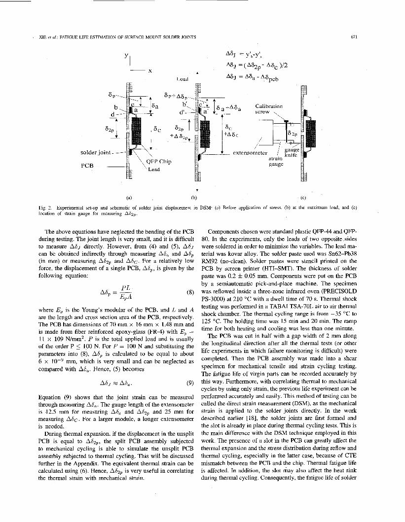
The experimental set-up is schematically shown in Fig. 2. The specimen is composed of a PCB and a quad flat pack (QFP) chip joined together by means of solder, very similar to a normal SMT assembly. Strain gauge extensometers are located at 62, ) 6c and 6,. Fig. 2(c) shows an extensometer for measuring 62p. The extensometer can be placed at any point between point d and the centre of the PCB. When measuring SC) the extensometer is attached to the component leads (point a) of the QFP chip as shown. Usually, only one extensometer was used for measuring SzP during strain cycling tests. Each knife edge of the extensometer was clamped by a plastic ring and no slippage was observed during testing. The basic correlation between these displacements and the joint strain are as follows:
(3) (4) ( 5 )
where
Displacement across the solder joint. Coordinate of the point, a, at the maximum tensile load. Coordinate of the point, b, at the maximum tensile load. Length of extensometer gauge across two split PCB’s. Total displacement between two split PCB’s. Displacement of chip. Thickness of the solder joint. Displacement across the solder joint and PCB. Displacement in a single PCB. Total shear strain of the solder joint. Corresponding strain to the displacement, A&,.
XIE et al.: FATIGUE LIFE ESTIMATION OF SURFACE MOUNT SOLDER JOINTS 67 1
+ (a) (b) (c)
Fig. 2. Experimental set-up and schematic of solder joint displacement in DSM: (a) Before application of stress, (b) at the maximum load, and (c) location of strain gauge for measuring A6zp.
The above equations have neglected the bending of the PCB during testing. The joint length is very small, and it is difficult to measure ASJ directly. However, from (4) and (5), AS, can be obtained indirectly through measuring AIS, and A6, (in mm) or measuring A&, and A&. For a relatively low force, the displacement of a single PCB, Ad,, is given by the following equation:
P L A6 -- - E,A
where Ep is the Young's modular of the PCB, and L and A are the length and cross section area of the PCB, respectively. The PCB has dimensions of 70 mm x 16 mm x 1.48 mm and is made from fiber reinforced epoxy-glass (FR-4) with Ep = 11 x 109 N/mm2. P is the total applied load and is usually of the order P 5 100 N. For P = 100 N and substituting the parameters into (8), As, is calculated to be equal to about 6 x mm, which is very small and can be neglected as compared with As,. Hence, (5) becomes
Equation (9) shows that the joint strain can be measured through measuring As,. The gauge length of the extensometer is 12.5 mm for measuring As, and ASzp and 25 mm for measuring A&. For a larger module, a longer extensometer is needed.
During thermal expansion, if the displacement in the unsplit PCB is equal to Asap, the split PCB assembly subjected to mechanical cycling is able to simulate the unsplit PCB assembly subjected to thermal cycling. This will be discussed further in the Appendix. The equivalent thermal strain can be calculated using (6). Hence, AS2, is very useful in correlating the thermal strain with mechanical strain.
Components chosen were standard plastic QFP-44 and QFP- 80. In the experiments, only the leads of two opposite sides were soldered in order to minimize the variables. The lead ma- terial was kovar alloy. The solder paste used was Sn62-Pb38 RM92 (no-clean). Solder pastes were stencil printed on the PCB by screen printer (HTI-SMT). The thickness of solder paste was 0.2 4= 0.05 mm. Components were put on the PCB by a semiautomatic pick-and-place machine. The specimen was reflowed inside a three-zone infrared oven (PRECISOLD PS-3000) at 210 "C with a dwell time of 70 s. Thermal shock testing was performed in a TABAI TSA-70L air to air thermal shock chamber. The thermal cycling range is from -35 "C to 125 "C. The holding time was 15 min and 20 min. The ramp time for both heating and cooling was less than one minute.
The PCB was cut in half with a gap width of 2 mm along the longitudinal direction after all the thermal tests (or other life experiments in which failure monitoring is difficult) were completed. Then the PCB assembly was made into a shear specimen for mechanical tensile and strain cycling testing. The fatigue life of virgin parts can be recorded accurately by this way. Furthermore, with correlating thermal to mechanical cycles by using only strain, the previous life experiment can be performed accurately and easily. This method of testing can be called the direct strain measurement (DSM), as the mechanical strain is applied to the solder joints directly. In the work described earlier [18], the solder joints are first formed and the slot is already in place during thermal cycling tests. This is the main difference with the DSM technique employed in this work. The presence of a slot in the PCB can greatly affect the thermal expansion and the stress distribution during reflow and thermal cycling, especially in the latter case, because of CTE mismatch between the PCB and the chip. Thermal fatigue life is affected. In addition, the slot may also affect the heat sink during thermal cycling. Consequently, the fatigue life of solder

612 IEEE TRANSACTIONS ON COMPONENTS, PACKAGING, AND MANUFACTURING TECHNOLOGY-PART B, VOL. 19, NO. 3, AUGUST 1996
-1.5 -0.5 0.5 1.5 2.5
displacement, tizp, x0.125 mm Fig. 3. Hysteresis loops of QFP-44 solder joint system.
-+-- 1 cycle
2 cycles
43 cycles
86 cycles
_c
-a- 129 cycles
joints will certainly be modified by the presence of a slot in the PCB assembly. Thus, the specimen should not be slotted in order to simulate a practical SMT product. More importantly, the DSM results are applicable directly to practical SMT solder joints since the specimen is not required to have a slot in the PCB. After thermal cycling, the practical PCB assembly can be made to form shear specimens by proper cutting. Then a lot of mechanical testing including strain cycling and creep can be done on the practical SMT solder joints directly. While cutting, much care was taken to ensure no damage to the component and the leads.
Mechanical strain or stress cycling was performed using an INSTRON 4206 universal machine. It was conducted at room temperature and without dwell time at peak loads. The cycling was restrained at a low compressive displacement because a big compression force might cause severe bending of the PCB. Therefore, the cycling could be under asymmetrical loading or displacement. Typical hysteresis loops of a mechanical strained joint system (QFP chip-solder-PCB) are shown in Fig. 3. The strain cycling was run on QFP-44 solder joints from -0.135 mm to $0.2 mm. As seen from Fig. 3, well-behaved hysteresis loops with different elastic and plastic displacements have been generated. The loops tilt and become narrow as the number of strain cycles increases.
Iv. RESULTS AND DISCUSSIONS
A. Strain and StifSness Development During Mechanical Stress Cycling
related to the applied load by a factor K as The displacement of a compliant leaded chip, A b , is
fatigue beginning / i
6 B d 81 e,'a@aaawa
0 L , , ' ' ' ' ' ' "- ' " """ ' '
1 10 100 1000 10000
stress cycles, N
Fig. 4. Strain Ae J , Atzp, and stiffness IC variations during stress cycling.
Substituting (10) into (6), then
A&J = ( A S Z P - P/K) / (Zh) . (1 1)
It should be noted that the index K represents the stiffness of the module including leads and may vary. Its value may be calculated from the finite-element method (FEM). For QFE' gull-wing solder joints, the variables A&J,A&, and P can be measured experimentally and, hence, the stiffness coefficient K may be determined from (1 1). For J-leaded and leadless solder joints, AEJ cannot be obtained directly through measuring As,. In that case, it can be obtained from (1 1) by measuring
Fig. 4 shows the variations of strains A E J , A E ~ , and stiff- ness K of a QFP-44 gull-wing solder joint system during stress cycling. The applied load amplitude was 0.066 kN and remained constant during cycling. As the number of stress cycles increases, AEJ and A&zP increase gradually while K decreases. This shows that both the solder joints and
and P if K is known.

673 XIE et al.: FATIGUE LIFE ESTIMATION OF SURFACE MOUNT SOLDER JOINTS
( h )
Fie. 5. I:rac.togrq)h (a) and X-ray radiograph (h) of QFP-41 d d c r joints which Ihild iifter stre.;.; cyc4ing for 2520 c.ycles. Koic: The joint\ in (3) are the >amc :I\ those in (bJ. Two joint> on the right f d e d :it the leads and the orher tn'o failed at tht- d d e r .
leads yield smoothly during stress cycling. However, both the stiffness K and the strain A E ~ , showed an abrupt change at about 2230 cycles, indicating the beginning of fatigue failure, The solder joint system failed soon after the point. Four solder joints were found to be fractured at 2520 cycles. At the same time, seven leads were also found to be fractured. The fractograph in Fig. 5(a) clearly shows the occurrence of fracture at both leads and solder joints. There were also some cracks seen at the root of remaining leads of good solder joints. Fig. 5(b) shows the X-ray radiograph of the same joints of Fig. 5(a). Many pores were observed in the fractured solder joints in both Fig. 5(a) and (b). The diameters of big pores are greater than 0.1 mm. However, few pores appeared in unfractured solder joints as shown in the X-ray radiograph of Fig. 5(b). This confirms that the existence of pores in solder joints may well be a major cause of joint failure.
Similar results were obtained from a QFP-80 solder joint system. In Fig. 6, each specimen consists of 24 lead pairs. Tensile forces were applied along the longitudinal direction where the thermal expansion was greater. During cycling, the total applied strain was 3.2% and was kept constant throughout. Up to about 530 strain cycles, the index K changed slowly and the joint strain AE J and PIK were fairly constant. After that, K decreased sharply while the joint strain
0
P
fatigue failure
1 10 I00 1000
strain cycles, N
Fig. 6. Variations of joint strain and chip stiffness during strain cycling.
Fig. 7. QFP-80 chip assembly in a used hand phone, manufactured in 1990.
increased drastically. This suggests that fatigue occurred both at the leads and solder portion. Six solder joints were found to be fractured at the solder portion, thus leaving the joints freely movable. Three leads had cracks and the other joints had no obvious damage. Hence, the variations of K and AEJ can be used to determine whether the failure of leads or solder joints has occurred. As the joint strain AEJ is fixed during the cycling (controlled by A&,), it is possible to determine the relationship between the joint strain and the number of cycles to failure by simply measuring ASzp. It is also noted that values of K for QFP-80 were much smaller than those of QFP-44 due to the fact that the leads' height of QFP-80 was greater than that of QFP-44. Therefore, QFP-80 leads were more compliant and could sustain a higher strain as compared with QFP-44. The experimental results in Figs. 4 and 6 confirm the observation that both the leads and solder have developed a fatigue problem during mechanical cycling and the leads of QFT-44 and QFT-80 chips can exhibit fatigue at a relatively high stress or strain.
B. Fatigue Properties of Practical QFP-80 Joints
In order to understand fatigue behavior in a practical solder joint, a QFP-80 chip assembly was taken from a used hand phone as shown in Fig. 7. The chip was a UNIDEN UC1193 and the phone was assembled in 1990. To examine the effects of thermal cycling on the joint strain and index K , QFP-44 solder joints were thermally cycled between -35 "C to 125 "C for 1000 cycles before mechanical strain testing. Strain A&zp, AE J and index K of different QFP solder joints were

614 IEEE TRANSACTIONS ON COMPONENTS, PACKAGING, AND MANUFACTURING TECHNOLOGY-PART B, VOL. 19, NO. 3, AUGUST 1996
I
W" 6 1 d -
D- o
200
\ L O O
a- (d 0 4
3 .i 3 a % 3
Y
c.l
cd 0
newlv made ioints 0.1
fatigue i- 1 I 1
lead
01.0 Mech Mech Therm Meeh Mech 0.01
1 10 100 1000 10000 I cy 1OOOC) IOOOcy 1 C) 1 CY3
phone
QFP-44 Joints QFP-80 Joints strain cycles, N Flg 8 nieLhariica1 and thermal cycling. cy denotes cycles.
Stralns and stlffness of different QFP solder JOlntS With effects of Flg 9 companson with newly made joints @6zP = 0 462 mm )
Stran cycling of QFP-80 solder p n t s 1n a used hand phone in
taken from a certain cycle in the mechanical cycling with a total applied load of 66 N. Results are plotted in Fig. 8. The joint strain of thermally cycled solder joint almost had no change as compared with the original one. The joint strain after mechanical cycling for 1000 cycles has increased from 5.8% to 6.8%. The index K decreases after both the mechanical cycling and thermal cycling tests, while the mechanical cycling causes more decrease in K value. This shows that the mechanical cycling had a greater effect on the strain and stiffness K than the thermal cycling. The main reason is that the applied thermal strain was much smaller than the mechanical strain. The total joint strain in the thermal cycling was 0.69% (see Table I), roughly 10% of that in the mechanical cycling. The other explanation is that eutectic Sn-Pb solder has a low melting point and becomes more pliable at high temperature.
Fig. 8 also shows that in order to get the same joint strain, a larger strain, A E ~ , is required by a QFP-80 solder joint than a QFP-44 one. This indicates that QFP-80 solder joints could sustain a higher thermal expansion strain due to the low stiffness of its leads. In addition, both the strains A&zP and Ae, in the used QFP-80 chip joints increased markedly, whereas the stiffness K almost had no change in contrast to the newly made QFP-80 chip joints. This simply confirms that the solder joints in the used QFP-80 exhibited fatigue earlier than the leads as indicated by the load-strain cycling curve in Fig. 9. The load of solder joints for the used chip dropped about 30% at the first cycle as compared with that of a newly made one, suggesting that the solder of the hand phone joints had accumulated a certain fatigue before this test. This is demonstrated by the values of stiffness K and joint strain at the first cycle in Fig. 8. Fatigue was seen in the joints of the used hand phone at about 750 cycles, whereas for the newly made joints at around 1050 cycles. The fatigue load of the used hand phone joints was 0.035 kN, approximately half of the maximum load for the newly made joints (at the first cycle). However, the newly made joints showed fatigue much earlier, before the cycle of 50% load drop. This is because fatigue occurred at the leads. Furthermore, all the leads in the newly made joints were found to fracture at the end of the cycling test. The solder could sustain a higher number of strain cycles before its failure provided that the leads remained
in good conditions. On the other hand, the load of the joints in the used hand phone dropped gradually until the final fracture occurred at the solder. This indicates that the solder joints in the used hand phone have sustained a high number of cycles and low strain fatigue history. This corresponds roughly to 1000 cycles at a total displacement of 0.462 mm.
C. Fatigue Life Determined by A&, and A E ~ ~ As evident from the above discussion, the displacement
ASzp should provide a useful means for measuring the fatigue of solder joints. In practical service, however, solder joints exhibit fractures mostly at the solder portion but not at the leads. This behavior should be reflected by the DSM. As discovered from the above experiments, this may be achieved by decreasing applied load or strain during cycling test. This method would be the most accurate, but a very large number of strain cycles is usually required to arrive at the fatigue point. A simpler method is to increase the joint stress which is equal to the applied load divided by the joint area. This can be done by decreasing the area of the solder joints while keeping the load unchanged. The variations of the total stress with strain cycling for this type of QFP-44 solder joint are shown in Fig. 10. The total displacement ASzp and the crosshead speed were kept constant. There exists a critical point for stress dropping. For all applied total displacements, the critical point was at 50% stress drop. The solder joint begins to show failure beyond that point. Therefore, a 50% load drop is a useful criterion to define joint failure, in good agreement with other experimental results [18]. It is also found that the joints were fractured mostly at the solder portion, although some leads were fractured at the displacement of 0.388 mm.
Fig. 11 shows the fatigue life as a function of the applied displacement which is plotted as several straight lines in the log-log chart. For a 50% stress failure definition, the correlation between the displacement A&, and the number of cycles to failure N f can be approximated by following empirical equation:
AS^^ = 0.99~;' 26 (mm). (12)
Equation (12) has a correlation coefficient of 0.986 and is reasonably accurate in use. Fig. 12 shows a plot of the

XIE et al.: FATIGUE LIFE ESTIMATION OF SURFACE MOUNT SOLDER JOINTS 615
loo 1 QFP-44 joints f=0.14Hz
50% load drop
mi rn 0 e
A s 2p = 0.263 0.338 0.388 (mm) t
TABLE I SPECIMENS AND STRAIN CYCLING TESTS EMPLOYED IN THIS STUDY AS
COMPARED WITH OTHER RESEARCHERS (FAILURE DEHNTION IS 50% LOAD DROP)
Strain neJ = CN! (frequency
C b No Researchers Specimen Solder teE:y-
No dwell time
1 This study QFP- Sn62 0.14Hz 2.57 -0.61 44PCb Pb38 25 "C
2 Solomon QFP- Sn63 0.33 Hz NIA NIA (1992) 64PCb Pb37 35 OC
3 Solomon single Sn60 0.3 Hz 1.14 -0.51 (1986) shear Pb40 -50
Cn/Cn 15OOC
1 ' ' ' " " " ' ' ' " " " ' ' ' " " " ' looo Solomon [6] as follows: 1 10 100
strain cycles, N A E J ~ = 1.14Nj-0.51. (13) Fig. 10. displacement.
Variations of total stress with strain cycle under different total
QFP-44 solder joint, pad width=0.3 mm l o 1 f=0.14Hz.
E E 2 m
0 X
1 ' " " " " ' ' " " " " ' " " " " ' " " " "
1 10 100 1000 10000
fatigue life, N , cycles Fig. 11. Fatigue life of solder joints versus total displacement,
experimental results versus the theoretical prediction from (12), and compares with the data of Solomon [18]. The experimental conditions are listed in Table I. Fig. 12 shows that the results obtained by Solomon are in good agreement with the experimental data of this work as well as with (12). This is because the specimens and strain cycling conditions adopted in this work are similar to those of Solomon's. The stiffness constant ( K ) of QFP-44 is close to that of QFP-64, as they have a similar configuration. The slot in the PCB has a negligible effect on the fatigue life provided that only the isothermal cycling test is performed on the specimen. It should be noted that ASzp is the total displacement resulting from the chip, solder joints, and PCB. In order to make comparison be- tween different specimens and joint configurations, one shoud use AEJ to correlate the fatigue life as in Coffin-Manson's equation. When estimating the fatigue of eutectic lead-tin solder, the most common empirical equation is obtained by
Fig. 12 shows the variations of fatigue life with joint strain obtained by the DSM method. The theoretical prediction from (13) is also plotted in the same figure for comparison. From that, it can be seen that the joint strain obtained by the DSM test is close to that of Solomon [6] even though it is a little higher for the case of lower fatigue life. The difference is mainly due to the fact that the strain in the DSM test is the total strain and should be larger than the plastic strain by about 10% [ 111. The other likely reason could be the lower cycling frequency adopted in this work than that of Solomon [6]. In summary, Adzp can be regarded as a controlled strain in the DSM fatigue test, generally applicable to many types of surface mount solder joints. Equation (6) is useful to correlate the joint strain with the controlled strain. In this manner, the number of cycles to failure in the fatigue test may be associated with the joint strain through the Coffin-Manson's Equation (13).
Thermal strain can be conveniently applied to a joint during thermal shock testing or thermal cycling. Combining mechani- cal and thermal cycling is a good way to do fatigue testing. The damage model for combined thermal and mechanical cycling may be expressed in the following modified form:
where n is the number of cycles conducted, N is the number of cycles to failure under single type of strain cycling, subscripts t and m represent thermal cycling and mechanical cycling, respectively, and Ct is a coefficient to correlate the fatigue damage between mechanical and thermal cycling. It is noted that n, is the number of remaining mechanical cycles to failure after nt thermal cycles have been exercised on the solder joints. Normally, Nt and N , are constant if the joint dimensions and strain cycling conditions are unchanged. Since n, is easily measured by direct measurement, nt can be assigned to any value from 0 to Nt. Therefore, the fatigue damage can be determined through measuring n,.
The experimental results are summarized in Table I1 and the number of predicted remaining cycles to failure (n,) are also plotted in Fig. 13. As seen from Fig. 13(a) and (b), the number

616 IEEE TRANSACTIONS ON COMPONENTS, PACKAGING, AND MANUFACTURING TECHNOLOGY-PART B, VOL. 19, NO. 3, AUGUST 1996
A6,p= 0.99 Nf026
\ e DSM A Solomon
0.1 ' ' " " ' I I I
1 I Q , 100 1000 I QOOQ
Fatigue life, N, cycles Fig. 12. Comparison of the fatigue lives at 50% load drop obtained from
1000 1 the DSM with data from Solomon (1992).
1000 E
I ' ' ' " " " 1 ' " " ' - ' " " " " I
1 10 100 1000 I 10 100 1000
Thermal cycles Thermal cycles (a) (b)
Fig 13 Fatigue lives of solder Joints under both thermal cycling and mechanical stran cycling in shear specimen (a) and QFP-44 Jolnts (b)
'The negative stram means that the displacement of PCB is less than that of the chlp
Fig. 14. Thermal stram calculatlons of QFP-44PCB assembly.
of remaining cycles to failure obtained from experiments is in good agreement with that calculated from (14).
ricated from a conventional reflow process, the following conclusions can be drawn:
1) The DSM developed in this work is found to be useful in practice and should provide a novel and direct technique to measure stress-strain properties of SMT solder joints. It is of practical use in predicting the fatigue life of a real
V. CONCLUSION
From a systematic and experimental investigation of the stress-strain properties of surface mount solder joints fab-

XIE et al.: FATIGUE LIFE ESTIMATION OF SURFACE MOUNT SOLDER JOINTS 671
TABLE I1 If the length of the slot is great enough so that the PCB can be PARAMETERS IN (2) AND FIG 9 FOR DIFFERENT SOLDER JOINTS considered to be split completely into two equal PCB’s, them Specimen Shear specimen QFP-44 the PCB will expand independently during thermal cycling. In
Fig 14, a small PCB will expand from its own central line. Mm 550 cycles 524 cycles
The direction of the expansion is opposite to that of the A b . Nt 5200 cycles 3900 cycles
Then the correspondent joint strain is Ct
(-44)
0.49 0.22
220(1 - (&)“’) 327.5(1 - (*)’”) nm(spIit)
AEJ,siit = (Adp + Adc)/(2h)
solder joint. The specimen does not initially have a slot inference and can simulate a practical PCB assembly to the greatest degree of accuracy.
2) The stiffness index K and A ~ J or Adzp are good indicators to show the fatigue status of solder joints. When A ~ J increases, the solder joints develop fatigue. When K decreases, the chip leads develop fatigue. When A E ~ , increases, the leaded solder joint system including both the solder joints and leads develop fatigue.
3) QFP-80 has lower lead stiffness than QFP-44, and therefore may sustain a higher mechanical or thermal strain for the same fatigue lifetime.
4) The measurement of total displacement ASzp can be recommended as a practical technique to estimate the fatigue life during strain cycling tests for both leaded and leadless solder joints. The equation AEJ = (Adzp - P/K) / (2h ) is used to correlate the total displacement with the total joint strain. The correlation between the joint strain and fatigue life for QFP lead joints, as measured by this work, is in good agreement with the Coffin-Manson’s equation.
APPENDIX
Analysis of Thermal Strain in Slotted and Split PCB Assemblies As described earlier in this paper, during thermal cycling
ASzp and Adc can represent the total thermal displacements of the whole PCB and chip, respectively. For a uniform rise of temperature AT (AT 2 0), if the displacements are unrestrained it follows that
Adzp = apLcAT (All
and
ASc a c L, AT + al (Lc - L,)AT (A2)
where aip, ac , and a1 are the coefficients of thermal expansion (CTE’s) of the PCB, chip, and lead, respectively, L c is the distance between two opposite pairs of solder joints, and L, is the length of the chip module. As shown in Fig. 14, the PCB has only a slot with a width of s and a length less than the width of the chip module. The thermal strain in the solder joints of the unslotted (or normal) PCB assembly at the longitudinal direction can be determined by (6). This is because the elastic strains are negligible [see (8)]. For the slotted PCB assembly in Fig. 14, the thermal displacement of the slotted part should be deducted. the joint strain in the slotted PCB assembly is thus
A ~ ~ , s l o t = ACJ - o ~ ~ s A T . (A31
and
ASp = ap[(Lp + ~ ) / 4 - Lc/2]AT/h (A5)
where Lp is the length of the whole unsplit PCB. Normally, A E J , ~ ~ ~ ~ ~ is greater than A E J , ~ ~ ~ ~ ~ and can be the maximum value of the joint strain in the slotted PCB assembly. An example is shown in Table I1 for calculating the joint strain in different cases of PCB assembly, assuming that the QFP-44 solder joints with a slot of 3 mm went under thermal cycling by AT = 160 “C (from -35 “C to 125 “C). It is learned from Table I1 that the joint strain in the slotted PCB assembly is dependent on the materials of both the chip and the PCB. For the plastic chip chosen in this work, the joint strain in the slotted PCB assembly varies from 1.59% to 16.9%. This is much greater than the joint strain in the unslotted PCB assembly (0.69%). For a ceramic chip, it varies from 6.23% to 9.16% and may be equal to the joint strain in the unslotted PCB assembly in special cases, Therefore, the slotted specimen cannot simulate the normal specimen in thermal cycling tests.
REFERENCES
[I] S. Vaynman, M. E. Fine, and D. A. Jeannotte, “Isothermal fatigue of low lead-based solder,’’ Metall. Trans., vol. 19A, pp. 1051-1059, 1988.
[2] A. Zubelewicz, Q. Guo, E. C. Cutiongco, M. E. Fine, and L. Keer, “Micromechanical method to predict fatigue life of solder,” J. Electron. Packag., vol. 112, pp. 179-182, June, 1990.
[3] Q. Guo, E. C. Cutiongco, L. M. Keer, and M. E. Fine, “Thermomechan- ical fatigue life prediction of 63Sd37Pb solder,” J. Electron. Packag., vol. 114, pp. 145-151, June 1992.
[4] H. H. Manko, Solders and Soldering, 3rd. ed. New York: McGraw- Hill, 1992, pp. 109-113.
[SI J. H. Lau and D. W: Rice, “Solder joint fatigue in surface mount technology: State-of-the-art,” Solid State Technol., vol. 28, pp. 9 1-104, Oct. 1985.
[6] H. D. Solomon, “Fatigue of 60/40 solder,’’ IEEE Truns. Comp., Hybrids, Manufact. Technol., vol. 9, pp. 423432, Dec. 1986.
[7] R. C. Weinhel, J. K. Tien, R. A. Pollak, and S. K. Kang, “Creep fatigue interaction in eutectic Pb-Sn solder alloy,” J. Mater. Sci., vol. 22, pp. 3901-3906, 1987.
[8] Z . Mei, J. W. Morris, Jr., and M. C. Shine, “Superplastic creep of eutectic tin-lead solder joints,” J. Electron. Packag., vol. 123, pp. 109-114, June 1991.
[9] Z. Mei and J. W Moms, Jr., “Fatigue lives on 60Sd4OPh solder joints mad with different cooling rates,” J. Electron. Packag., vol. 114, pp. 104-111, June 1992.
[lo] H. D. Solomon, “Low cycle fatigue of Sn96 solder with reference to eutectic solder and a high Pb solder,” J. Electron. Packag., vol. 113, pp. 102-108, June 1991.
1111 Z . F. Guo, A. F. Sprecher, D. Y. Jung, and H. Conrad, “Influence of . .
Environment on theFatigue of Pb-Sn solder joints,” ZEEE Trans. Comp., Hybrids, Manufact. Technol., vol. 14, no. 4, pp. 833-837, Dec. 1991.
[12] R. Sandstrom, J. 0. Osterberg, and M. Nylen, “Deformation behavior during low cycle fatigue testing of 60Sn-40Pb solder,” Mater. Sci. Technol., vol. 9, pp. 811-819, Sept. 1993.
[I31 D. R. Frear, “Thermomechanical fatigue of solder joints: A new compre- hensive test method,” ZEEE Trans. Comp., Hybrids, Manufact. Technol., vol. 12, no. 4, pp. 492-501, 1989.
[ 141 -, “ Microstructure evolution during thermomechanical fatigue of 62Sn-36Pb-2Ag and 60Sn40Pb solder joints,’’ IEEE Trans. Comp., Hybrids, Manufact. Technol., vol. 13, no. 4, pp. 718-725, Dec. 1990.

678 IEEE TRANSACTIONS ON COMPONENTS, PACKAGING, AND MANUFACTURING TECHNOLOGY-PART B, VOL. 19, NO. 3, AUGUST 1996
[15] N. Nir, T. D. Dudderar, C. C. Wong, and A. R. Storm, “Fatigue orooerties of microelectronics solder joints,” J. Electron. Packax., vol.
J. K. L. Lai, for a photograph and biography, see p. 153 of the February 1996 issue of this TRANSACTIONS.
I l i , pp. 92-113, June 1991. 1161 Y. H. Pao. R. Govila, S. Badglev, and E. Jih, “An experimental and ~~ - _
finite element study of thermal fatigue fracture of PbSn-solder joints,” I. K. Hui received the B.Sc. degree from Brighton University, U.K., and the MSc. degree from the University of Hong Kong.
In 1976, he joined Hong Kong Polytechnic as a Lecturer and was promoted to Senior Lecturer in 1981. From 1987 to 1991, he worked for NEC (Australia) and IEI (Australia) as a Senior Produc- tion Engineer and Production Manager, respectively. He joined the City Polytechnic of Hong Kong as a Senior Lecturer. He is now an Associate Professor of the City University of Hong Kong His research
J Electron Packag., vol. 115, pp 1-8, Mar. 1993. [17] S E Yamada, “A bonded joint analysis for surface mount components,”
J. Electron Packag., vol. 114, pp 1-7, Mar 1992 [18] H. D. Solomon, “Isothermal fatigue of LCCPWB Interconnections,” J.
Electron Packag., vol. 114, pp 161-168, June 1992. [19] J H Constable and C. Sahay, “Electncal resistance ass indicator of
fatigue,” IEEE Trans. Comp., Hybrids, Manufact. Technol., vol. 15, no. 6, pp. 1138-1145, Dec. 1992.
[20j C. Lizzul, J. H Constable, and G. Westhy, “Fatigue Investigation of lap shear solder joints using resistance spectroscopy,” in Proc. 44th ECTC, Washington, DC, May 1994, pp 458464.
- - activities and publications mainly center on surface mount technology.
Mr. Hui is a Chartered Engineer and a Chartered Professional Engineer.
D. J. Xie, for a photograph and biography, bet: p. 153 of the February 1996 issue of this TRANSACTIONS.
Yan C. Chan (SM’95), for a photograph and biography, see p. 153 of the February 1996 issue of this TRANSACTIONS.