fastrak: enabling express lanes in multi-tenant data...
TRANSCRIPT
FasTrak: Enabling Express Lanes in Multi-Tenant DataCenters
Radhika Niranjan Mysore George Porter Amin VahdatUC San Diego UC San Diego UC San Diego and Google
ABSTRACTThe shared nature of multi-tenant cloud networks requires provid-ing tenant isolation and quality of service, which in turn requiresenforcing thousands of network-level rules, policies, and trafficrate limits. Enforcing these rules in virtual machine hypervisorsimposes significant computational overhead, as well as increasedlatency. In FasTrak, we seek to exploit temporal locality in flowsand flow sizes to offload a subset of network virtualization func-tionality from the hypervisor into switch hardware freeing up thehypervisor. FasTrak manages the required hardware and hypervi-sor rules as a unified set, moving rules back and forth to minimizethe overhead of network virtualization, and focusing on flows (orflow aggregates) that are either most latency sensitive or exhibit thehighest packets-per-second rates.
Categories and Subject DescriptorsC.2.3 [Computer-Communication Networks]: Network Opera-tions; C.2.4 [Computer-Communication Networks]: DistributedSystems; C.4 [Performance of Systems]: Design studies
General TermsDesign, Performance, Management
KeywordsNetwork virtualization; Multi-tenancy; Policy enforcement; Soft-ware defined networking
1. INTRODUCTIONInfrastructure as a Service offerings such as Amazon EC2, Mi-
crosoft Azure and Google Compute Engine host an increasing frac-tion of network services. These platforms are attractive to appli-cation developers because they transparently scale with user de-mands. However, the shared nature of cloud networks requires en-forcing tenant isolation and quality of service, which in turn re-quires a large number of network-level rules, policies, and trafficrate limiting to manage network traffic appropriately. Enforcing
Permission to make digital or hard copies of all or part of this work for personal orclassroom use is granted without fee provided that copies are not made or distributedfor profit or commercial advantage and that copies bear this notice and the full cita-tion on the first page. Copyrights for components of this work owned by others thanACM must be honored. Abstracting with credit is permitted. To copy otherwise, or re-publish, to post on servers or to redistribute to lists, requires prior specific permissionand/or a fee. Request permissions from [email protected]’13, December 9âAS12, 2013, Santa Barbara, California, USA.Copyright 2013 ACM 978-1-4503-2101-3/13/12 ...$15.00.http://dx.doi.org/10.1145/2535372.2535386.
these policies comes at some cost today, which will only grow asdemand for these offerings increase.
Today, many multi-tenant offerings provide tens of thousands ofcustomers with virtual network slices that can have hundreds ofsecurity and QoS rules per VM [3]. Such networks must provideisolation for thousands of flows per virtual machine, or tens of thou-sands of flows per physical server, and up to hundreds of thousandsof flows per Top of Rack (ToR) switch. This enormous set of rulesmust be accessed on a per-packet basis to enable communicationand isolation between tenants. The virtual machine hypervisor typ-ically enforces these rules on every packet going in and out of thehost.
This results in problems for both the provider and the customer:for the provider, resources that could be used to support more usersmust instead be diverted to implement these network-level rules;for the customer, the myriad rules implemented within the hyper-visor are a source of increased latency and decreased throughput.
In FasTrak, we seek to reduce the cost of rule processing rec-ognizing that the associated functionality is required. We exploittemporal locality in flows and flow sizes to offload a subset of net-work virtualization functionality from the hypervisor into switchhardware in the network itself to free hypervisor resources. Fas-Trak manages the required hardware and hypervisor rules as a uni-fied set, moving rules back and forth to minimize the overhead ofnetwork virtualization, and focusing on flows (or flow aggregates)that are either most latency sensitive or exhibit the highest packets-per-second rates.
Due to hardware space limitations, only a limited number ofrules can be supported in hardware relative to what is required bya server. We argue that this gap is inherent and hence the key chal-lenge we address in this work is identifying the subset of flows thatbenefit the most from hardware/network offload, and coordinatingbetween applications, VMs, hypervisors, and switches to migratethese rules despite changes in traffic, application behavior, and VMplacement.
FasTrak seeks to achieve the following three objectives:1. Hardware network virtualization: The flows that bypass the
hypervisor should still be subject to all associated isolation rules.This include tunnel mappings, security and QoS rules associatedwith the flow.2. Performance isolation: Regardless of whether traffic is subjectto rule processing in the hypervisor or in hardware, the aggregatetraffic rate of each tenant’s VM should not exceed its limits. Like-wise, traffic from one tenant VM should not affect another’s, evenif non-overlapping subset of flows are offloaded to hardware.3. Performance: We seek to improve both available applicationbandwidth and to reduce both average and tail communication la-tency.

Based on these goals, we design, prototype and evaluate FasTrak.We rely on pre-existing technology trends. Hardware with signifi-cant levels of network virtualization support, such as tunneling of-floads for NICs [16] and switches [4] are becoming commodity.The core of our design consists of an SDN controller that decideswhich subset of active traffic should be offloaded, and a per-VMflow placement module that directs selected flows through eitherthe hypervisor, or through an SR-IOV [14]-based “FasTrak” path.The flow placement module integrates with an OpenFlow interface,allowing the FasTrak controller to program it. In our design, thenetwork fabric core remains unchanged.
The primary contribution of this work is a demonstration thatoffloading a subset of flows to an in-network hardware fast pathcan result in substantial performance gains while minimizing ruleprocessing overhead in servers. We motivate our work with a mi-crobenchmark study that gives us insights into where network la-tencies and CPU overheads lie in existing virtualized systems. Fur-ther, we examine which types of flows are most subject to this ruleprocessing overhead. We then describe FasTrak design and evalu-ate it on a testbed. In this evaluation, we find that applications seea∼ 2x improvement in finish times and latencies while server loadis decreased by 21%. While the actual benefits of FasTrak will beworkload dependent, services that benefit the most are those withsubstantial communication requirements and some communicationlocality.
2. BACKGROUNDWe first consider some of the characteristics and requirements of
multi-tenant virtualized data centers, then briefly summarize hostand NIC support for network virtualization.
2.1 Requirements of multi-tenant data centersMulti-tenant data centers employing network virtualization seek
an abstraction of a logical private network controlled and isolated inthe same way as a dedicated physical infrastructure. The propertiestypically sought out in such networks are:Control (C1). A tenant must be able to assign any IP address to
their VMs, independent of the IP addresses used by other tenants,or the IP addresses assigned by the provider to physical servers.The network must support overlapping tenant IP addresses, e.g., inseparate private RFC 1918 [1] address spaces.Control (C2). Security and QoS rules that tenants would apply
to traffic in their private deployment should be enforceable in themulti-tenant setting.Isolation (I3). The provider of a multi-tenant data center must
be able to distinguish tenant traffic, enforce tenant-specified rules,and rate limit incoming and outgoing bandwidth allocated to ten-ant VMs. No single tenant should be able to monopolize networkresources.Seamlessness (S4). VM migration should be transparent to
the customer and should not require change in the IP address orconnectivity. Security and QoS rules pertaining to the VM shouldmove automatically along with the VM.
These requirements impact the design of the network. To enableC1, tenant IP addresses must be decoupled from provider IP ad-dresses. Tenant IP addresses should encode the identities of VMs,while the provider IP addresses should indicate their location andaid in forwarding across the network fabric. Tunneling packets car-rying tenant IP addresses across the provider network helps achievethis separation. Further, to distinguish tenant traffic from one an-other despite overlapping IP addresses, every packet must be taggedwith a tenant ID. This tenant ID also helps achieve I3, by informingthe network of which rules to apply to the packet. For C1, the net-
work must maintain mappings between the tenant VM’s IP addressand the tenant ID, as well as to the tunnel provider’s IP addressfor every destination VM that a source VM wants to communicatewith.
To support C2, the network must store and enforce all relevantsecurity and QoS rules associated with a tenant VM. For example,Amazon Virtual Private Cloud(VPC) [3] allows up to 250 securityrules to be configured per VM. These rules are typically maintainedclose to the communicating VMs and applied on a per-packet basis.
The network must support tenant-specific rate limits that can beapplied to network interfaces to support I3. Finally, to ensure S4,the network should migrate all the above rules pertaining to everyVM along with the VM. Tunnel mappings should be updated bothat source and destination of every traffic flow.
A multi-tenant data center with tens of thousands of tenants muststore and orchestrate a considerable amount of network state, andmust consult much of this state on a per-packet basis. In termsof manageability, this high volume of state encourages a softwareapproach to network virtualization, where the network state corre-sponding to every VM is held in the hypervisor of the server onwhich it is resident.
2.2 Virtualized Host NetworkingHypervisor-based: A virtual switch in the hypervisor, called thevswitch, manages traffic transiting between VMs on a single host,and between those VMs and the network at large. In a multi-tenantsetting the vswitch is typically configured to isolate traffic of VMsbelonging to different tenants. Such a vswitch can tag traffic withtenant IDs, maintain and enforce tunnel mappings, security, QoSrules and interface rate limits.
A widely-deployed vswitch implementation is Open vSwitch (OVS)[13]. Apart from invoking the kernel for per-packet processing,OVS provides a user-space component for configuration. In thiswork, we subject OVS to a series of microbenchmark tests to under-stand the effect of configuration settings (described in Section 3) onsoftware network virtualization overheads. We now describe theseconfigurations.
In its simplest configuration, OVS is a simple L2 software switch(herein referred to as ‘Baseline OVS’). Security rules can be con-figured using the user-space component. When OVS detects trafficthat it has not seen before, it forwards these packets to user-space,where the packets are checked against the configured security rules.Then a fast path rule corresponding to this traffic is installed in thekernel component, so that subsequent packets can be handled en-tirely by the kernel component. This component maintains the rulesin an O(1) lookup hash table to speed up per packet processing. Werefer to this configuration as ‘OVS+Security rules’.
OVS also supports configuration of rate limits using tc [17] onVM interfaces that connect to it. These interfaces are called virtualinterfaces (VIF) because they are purely software interfaces. Out-going traffic from the VM exit these interfaces and are first handledby the vswitch, which imposes the rate limit. The vswitch can thenforward this VM traffic on a physical NIC if it is destined to a re-mote host. Interface limits can be specified for incoming traffic aswell. We refer to configuration including this rate limit specifica-tion as ‘OVS+Rate limiting’.
It is also possible to configure OVS to tunnel packets in and outof the physical servers using VXLAN [19] tunneling. VXLAN is aproposed tunneling standard for multi-tenant data centers that alsospecifies the tunneling encapsulation format. In this configuration,an encapsulation with a destination server IP address is added toVM traffic exiting the server. This address is stripped from incom-
ing packets destined to local VMs. We refer to this configurationas ’OVS+Tunneling’.Hypervisor Bypass: Due to the overhead of transiting the hy-pervisor, VMs also have the option of bypassing the vswitch andhypervisor to send traffic in and out of a physical NIC directly. It isnecessary that the physical NIC interface is administratively con-figured to support this configuration for a given VM. Packets areDMAed directly between the NIC and the VM, and thus packetsneed not be copied to the vswitch. There are two key drawbacksto this configuration, however. First, this technique is not scalable:the NIC port automatically becomes unavailable for use by otherVMs; in contrast, the vswitch can help share a physical port acrossmultiple VMs using VIFs. Second, the traffic from the VM is nolonger virtualized at the physical server, and thus network policiesare no longer properly enforced.
To overcome the first problem, Single Root IO Virtualization(SR-IOV) [14] allows a single PCIe device to appear as multi-ple separate physical PCIe devices. With SR-IOV, the NIC par-titions hardware resources to support a number of virtual func-tions (VFs) that can be separately allocated to VMs. These VFscan share a physical port on a NIC up to some limit (e.g., 64).Packets are DMAed to and from the VM directly to the NIC us-ing the VF, avoiding the hypervisor copy and associated contextswitches. However, the processor and BIOS must support SR-IOVand provide IOMMU functionality so that the NIC can access VMmemory, and deliver received packets directly without hypervisorintervention. VF Interrupts on the other hand are first deliveredto the hypervisor. This allows the hypervisor to isolate interruptssecurely.
The second issue raised is a key motivation for FasTrak, as sup-porting flexible offload of network rules to the network is neces-sary to fully realize the benefits of lower latency and lower CPUinvolvement in virtualized multi-tenant data centers.
3. POTENTIAL FASTRAK BENEFITSSupporting the myriad rules and network policies underpinning
multi-tenant data centers has largely become the responsibility ofthe hypervisor. However, the raw CPU cost on a per-packet basisfor supporting network virtualization can be substantial. As virtu-alized workloads become more communication intensive, and re-quired line rates increase, we expect this overhead to grow. In thissection, we examine these overheads, measuring the impact of soft-ware processing on application throughput and latency. We thenexamine the effect of bypassing the hypervisor using SR-IOV. Inthis way, we can estimate an upper-bound on the potential benefitthat FasTrak can deliver, as well as better understand which typesof network flows will benefit the most from FasTrak.
3.1 Microbenchmark setupWe have setup a small testbed consisting of a pair of HP DL380G6
servers, each with two Intel E5520 CPUs and 24 GB of memory.The servers run Linux 3.5.0-17, the hypervisor is kvm, and guestVMs run Linux 3.5.0. Each VM is equipped with a software virtualinterface (VIF) connected to the vswitch (which is OVS), and eachNIC also supports an SR-IOV VF. The vswitch can be configured inany of the above mentioned configurations. The network interfacesbelonging to VMs and servers used in our tests have TSO and LROenabled with MTU set to 1500 bytes(which is the normal setting indata centers based on our conversation with operators). The work-load we evaluate is netperf [12], measured with four different ap-plication data sizes: 64, 600, 1448, 32000 bytes. We first describehow we measure the network overheads of OVS as compared toSR-IOV, and then describe how we measure CPU overheads.
Figure 1: Relative CPU overhead measurement setup
Figure 2: Performance measurement setup
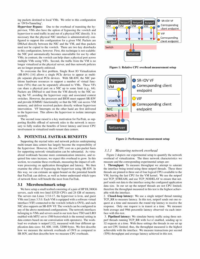
3.1.1 Measuring network overheadFigure 2 depicts our experimental setup to quantify the network
overhead of virtualization. The three network characteristics wemeasure and the corresponding experimental setups are:1. Throughput: To measure throughput we attempt to saturatethe interface being tested using three netperf threads. These threethreads are pinned to three out of four logical CPUs available to theVM, leaving the last CPU for the VM kernel. We use the netperftest TCP_STREAM, and use TCP_NODELAY to ensure that net-perf sends out data to the interface using the configured applicationdata size. In our set up the netperf threads are not CPU limited;therefore the throughput measured in this test is the highest achiev-able with the interface.2. Closed-loop latency: We use a single netperf thread runningTCP_RR to measure latency. In this test, netperf sends out one re-quest at a time and measures the round trip latency to receive theresponse. Only one request is in transit at a time. We measureboth average and 99th percentile latency observed via each inter-face with this test.3. Pipelined latency: We simulate bursty traffic using three net-
perf threads running TCP_RR with burst enabled, sending up to32 requests at a time. With these settings the threads in our set upare not CPU limited; thus, the throughput measured is the highestachievable with the interface. We measure transactions per second(TPS) throughput and average latency achieved in this test.

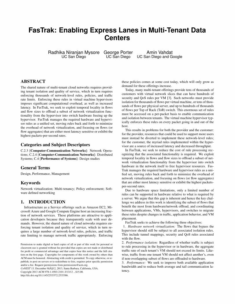
3.1.2 Measuring CPU overheadTo quantify the CPU required to drive each interface, we rely
on the experiment shown in Figure 1. Four test VMs on a singlephysical server each run a single threaded netperf TCP_STREAMtest with the TCP_NODELAY option enabled. We measure thetotal level of CPU utilization during the test.
3.2 Microbenchmark ResultsFigure 3 shows the results for network performance measure-
ments obtained through the VIF on the hypervisor with three OVSconfigurations: Baseline, OVS+Tunneling and OVS+Rate limitingin comparison with that obtained by bypassing the hypervisor withSR-IOV. Figure 4(a) shows the CPU overhead with the same con-figurations.
Figures 3(a), 3(b), 3(c) show that SR-IOV delivers significantlyhigher throughput and lower average and 99th percentile latency.Figure 3(d) shows that when pipelining requests, SR-IOV deliversup to twice the transactions per second as compared to baselineOVS. Figure 4(a) shows that the CPU required to drive the SR-IOV interface is 0.4-0.7x lower than baseline OVS. With SR-IOV,the hypervisor only isolates interrupts from the VM and leaves theremaining work to the guest VM.
We next traced the system stack (not shown) on those CPU coresdedicated to the host kernel when running the CPU test with base-line OVS. This trace showed that the host CPU spent 96% of timein network I/O (inclusive of servicing interrupts), and up to 55% oftime copying data. This is in marked contrast with SR-IOV, wherethe host CPU was idle 59% of the time and spent 23% of the timeservicing interrupts. Thus the OVS overheads are intrinsic to hyper-visor packet handling. In fact due to an efficient O(1) implemen-tation for accessing security rules, the same tests measured withan OVS instance populated with 10, 000 security rules showed nomeasurable difference in overhead compared with baseline OVS.
3.2.1 Overhead of VXLAN tunnelingThe current OVS tunneling implementation was not able to sup-
port throughputs beyond 2 Gbps for our target application datasizes. A component of this limitation is that UDP VXLAN packetsdo not currently benefit from NIC offload capabilities. Figures 3(b)and 3(c) show that software tunneling does indeed add to latency.Supporting a link with software tunneling at 1.96 Gbps with TCPrequires 2.9 logical CPUs with 1448-byte application data units(shown in Figure 4(a)). A stack trace during TCP_STREAM testsshowed that tunneling adds 23% overhead relative to baseline OVS.Some of the overhead stems from the fact that the network stack hasto additionally decapsulate the packet before it can be processed.We suspect that there are some inefficiencies in current code thatcauses lookups on VXLAN packets to be much slower than forregular packets. As such the poor performance with tunneling islikely not fundamental, and further engineering should improve thetunneling implementation.
3.2.2 Overhead of rate limitingWe configured a rate limit of 10 Gbps on the hypervisor VIF
while measuring the overhead of queuing and dequeuing packets inhtb. We found that the latency is somewhat higher (shown in Fig-ures 3(b) and 3(c)) than baseline OVS, while the throughput (shownin Figure 3(a)) is similar. The effect on pipelined latency (shownin Figure 3(e)) and transactions per second (shown in Figure 3(d))is more pronounced, with rate limiting reducing the TPS up to 85-88% of baseline.
To measure CPU overhead of rate limiting, we configure a ratelimit of 5Gbps for each of three VMs, oversubscribing the 10Gbps
physical interface by a factor of 1.5x. As seen in Figure 4(a), wecannot achieve line rate with four netperf threads, which we areotherwise able to do with baseline OVS. Furthermore, the samenumber of logical CPUs as baseline are used to drive the link, eventhough we are achieving lower throughput.
3.2.3 Overhead of combined tunneling and rate lim-iting
Having observed each software network virtualization function-ality in isolation, we now focus on examining the composition ofthese functions. Because of the inefficiencies in tunneling imple-mentation, we are limited to rates below 1.44 Gbps for these exper-iments, and so we apply a rate limit of 1 Gbps. We also configurethe same rate limit on the SR-IOV interface, and we note that thislimit is enforced in the NIC hardware. Figure 5 shows the resultsof the comparison. The average and 99th percentile of latency, theTPS, and pipelined latency of the composed functionality (OVS,tunneling, and rate limiting) are closer to the performance seen withOVS+Tunneling. The pipelined latency is between 1.8-2.1x largerthan SR-IOV, as shown in Figure 5(e). The CPU overhead of thiscombination is still 1.6-3x that seen with SR-IOV, as shown in Fig-ure 4(b). SR-IOV delivers consistently better throughput overall,as shown in Figure 5(a).
3.2.4 SummaryThe above results, and Figure 4 show that as application data
size decreases, the CPU required to support the same throughputincreases. This is a consequence of virtualization rules being ap-plied on a per-packet basis. As link rates increase, handling eachof these per-packet processing steps is increasingly infeasible. Al-ready NICs provide considerable hardware assist to servers to de-liver high link rates at lower CPU utilization, including TCP TSOand LRO. By having the hypervisor responsible for enforcing pol-icy on a per-packet basis, we potentially lose the ability to scalewith hardware assist in the future.
Baseline OVS without any security rules, without tunneling, andwithout rate limiting support adds considerable overhead simplydue to required kernel crossings. A more subtle effect is that thepercentage of improvement in latency increases when a flow ismoved from the hypervisor to the SR-IOV interface, based on datasize, throughput remaining same. As the application data size de-creases, latency improvement increases with hardware offload. Forexample, when moving flows from baseline OVS to SR-IOV, thepipelined latency improvement increases from 30% for 32000 byteapplication data sizes to 49% for 64 byte sizes. With OVS and ratelimiting, the improvement increases from 32% for 32000 byte ap-plication data units to 56% for 64 byte application data units (weomit comparing to tunneling due to the performance issues we ob-served). This is expected: As the data size decreases, throughputremaining constant. the packets per second rate of the flow in-creases. Per Little’s law [10], average queue lengths built up in hy-pervisor and hence average packet delay is directly proportional tothe packets per second rate (arrival rate). As we offload flows withhigher packets per second rates to the hardware path (which pro-cesses packets faster, and with more predictable delays than soft-ware), the average latencies experienced by VM traffic overall mustreduce faster.
In summary, offloading flows with the highest packet per secondrates is going to provide the largest improvements both in termsof CPU overhead and latency overhead. Based on these results,we now consider how FasTrak might benefit both multi-tenant datacenter customers and providers.

(a) Throughput (b) Average Latency (c) 99th %ile Latency
(d) Burst TPS (e) Burst Latency
Figure 3: Baseline Network performance
(a) Baseline CPU overhead (b) Combined CPU overhead
Figure 4: CPU Overheads
Figure 3(d) shows that a bursty application with 64-1448 appli-cation data sizes achieves an average TPS of 60K with SR-IOV,and 34K with baseline OVS (or 25K with OVS and tunneling, and30K with OVS and rate limiting). As an example, achieving a tar-get TPS of 120K requires two VMs with SR-IOV, but four VMswith baseline OVS. Thus, for communication-intensive applica-tions, customers can cut their costs when they use VMs with SR-IOV interfaces.
Looking at this example from the provider’s point of view, Fig-ure 4(b) shows that, on average, a VIF consumes 1.6-3x the CPU ascompared to SR-IOV. If we consider that two logical CPUs are ap-proximately as powerful as an Amazon EC2 medium instance [20],we can compute an estimate of the potential cost savings. The pric-ing for this instance type is approximately $821 per year [2]. If theprovider can save a total of two logical CPUs by avoiding networkprocessing, they can save $821 per server per year.

(a) Throughput (b) Average Latency (c) 99th %ile Latency
(d) Burst TPS (e) Burst Latency
Figure 5: Combined Network Performance
Given that commodity NICs today support hypervisor bypassthrough SR-IOV, we now propose a way to leverage that supportto lower overall network virtualization costs while improving ap-plication performance.
4. FASTRAK ARCHITECTURESoftware network virtualization allows for the massive scale re-
quired of multi-tenant data centers; but the CPU overheads come atnon-zero cost to the provider, and the additional latency can havenegative effect on application performance. Commodity networkhardware on the other hand can handle a subset of network virtual-ization functions such as Generic Routing Encapsulation (GRE) [7]tunnel encap, rate limiting and security rule checking, at line rateand lower latency. However, it is fundamentally limited by thenumber of flows for which it can provide this functionality due tofast path memory limitations. It is also limited in flexibility. For ex-ample, it cannot trivially do VXLAN encapsulation until new hard-ware is built and deployed. FasTrak splits network virtualizationfunctionality between hardware and software. It manages the re-quired hardware and vswitch rules as a unified set and moves rulesback and forth to minimize the overhead of network virtualization,focusing on flows (or flow aggregates) that are either most latencysensitive or the highest packets-per-second rates.
In this section, we first provide a brief overview of the FasTrakcontrol and data plane functionality. The goal is to provide a com-prehensive view of how FasTrak fits in and leverages existing ker-nel and hardware support to create “express lanes,” or hypervisorbypass paths. We then describe the detailed design of FasTrak thatfocuses solely on how FasTrak decides which flows to migrate, andhow it chooses their path.
Figure 6: FasTrak: Control Plane Overview
4.1 Control PlaneFigure 6 shows the FasTrak control plane. FasTrak makes two
paths available for VM traffic: one through the vswitch, and a sec-ond one through the SR-IOV bypass mechanism. The FasTrak rulemanager offloads network virtualization rules to and from hardwarein response to traffic patterns and VM migration events. These rulesnot only include tenant security ACLs and QoS rules, but also tun-nel mappings required to isolate tenant traffic. We rate limit VMtraffic on both the software and hardware paths to a target aggre-gate, e.g., the total amount of bandwidth available to a tenant/VM.
4.1.1 Enabling hardware ‘express lanes’In FasTrak, each guest VM running on a FasTrak-enabled hyper-
visor is given two paths to the network: one based on bypassing thehypervisor via SR-IOV, and one based on transiting the default VIF
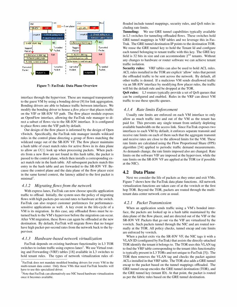
Figure 7: FasTrak: Data Plane Overview
interface through the hypervisor. These are managed transparentlyto the guest VM by using a bonding driver [9] for link aggregation.Bonding drivers are able to balance traffic between interfaces. Wemodify the bonding driver to house a flow placer that places trafficon the VIF or SR-IOV VF path. The flow placer module exposesan OpenFlow interface, allowing the FasTrak rule manager to di-rect a subset of flows via to the SR-IOV interface. It is configuredto place flows onto the VIF path by default.
Our design of the flow placer is informed by the design of OpenvSwitch. Specifically, the FasTrak rule manager installs wildcardrules in the control plane directing a group of flows matching thewildcard range out of the SR-IOV VF. The flow placer maintainsa hash table of exact match rules for active flows in its data planeto allow an O(1) look up when processing packets. When pack-ets from a new flow are not found in this hash table, the packet ispassed to the control plane, which then installs a corresponding ex-act match rule in the hash table. All subsequent packets match thisentry in the hash table and are forwarded to the SR-IOV VF. Be-cause the control plane and the data plane of the flow placer existin the same kernel context, the latency added to the first packet isminimal1.
4.1.2 Migrating flows from the networkWith express lanes, FasTrak can now choose specific application
traffic to offload. Initially, the system uses the policy of migratingflows with high packets-per-second rates to hardware at the switch.FasTrak can also respect customer preferences for performance-sensitive applications as well. A key event in the life-cycle of aVM is its migration. In this case, any offloaded flows must be re-turned back to the VM’s hypervisor before the migration can occur.After VM migration, these flows can again be offloaded at the newdestination. By default, FasTrak will migrate flows that no longerhave high packet-per-second rates from the network back to the hy-pervisor.
4.1.3 Hardware-based network virtualizationFasTrak depends on existing hardware functionality in L3 TOR
switches to isolate traffic using express lanes2. We use Virtual rout-ing and Forwarding (VRF) tables [18] available in L3 switches tohold tenant rules. The types of network virtualization rules of-1FasTrak does not mandate modified bonding drivers for every VM in themulti-tenant data center. Only those VMs that need FasTrak benefits willhave to use this specialized driver.2Note that FasTrak can alternatively use NIC based hardware virtualizationonce it becomes available.
floaded include tunnel mappings, security rules, and QoS rules in-cluding rate limits.Tunneling: We use GRE tunnel capabilities typically availablein L3 switches for tunneling offloaded flows. These switches holdGRE tunnel mappings in VRF tables and we leverage this in Fas-Trak. The GRE tunnel destination IP points to the destination TOR.We reuse the GRE tunnel key to hold the Tenant Id and configureeach tunnel belonging to tenant traffic with this key. The GRE keyfield is 32 bits in size and can accommodate 232 tenants. Withoutany changes to hardware or router software we can achieve tenanttraffic isolation.Security rules: VRF tables can also be used to hold ACL rules.ACL rules installed in the TOR are explicit ‘allow’ rules that permitthe offloaded traffic to be sent across the network. By default, allother traffic is denied. If a malicious VM sends disallowed trafficvia an SR-IOV interface by modifying flow placer rules, the trafficwill hit the default rule and be dropped at the TOR.QoS rules: L3 routers typically provide a set of QoS queues thatcan be configured and enabled. Rules in the VRF can direct VMtraffic to use these specific queues.
4.1.4 Rate limits EnforcementUsually rate limits are enforced on each VM interface to only
allow as much traffic into and out of the VM as the tenant haspaid for. This prevents any single tenant from unfairly depletingavailable bandwidth on the access link. Since FasTrak exposes twointerfaces to each VM by default, it enforces separate transmit andreceive rate limits on each of them such that the aggregate transmitand receive rates are close to the allowed limits for the VM. Theserate limits are calculated using the Flow Proportional Share (FPS)algorithm [34] applied to periodic traffic demand measurements.As demands change, the rate limits imposed also are changed. Ratelimits on the software VIF are imposed at the hypervisor, while therate limits on the SR-IOV VF are applied at the TOR (or if possibleat the NIC).
4.2 Data PlaneNext we consider the life of packets as they enter and exit VMs.
Figure 7 shows how the FasTrak data plane functions. All networkvirtualization functions are taken care of at the vswitch or the firsthop TOR. Beyond the TOR, packets are routed through the multi-tenant data center network core as usual.
4.2.1 Packet TransmissionWhen an application sends traffic using a VM’s bonded inter-
face, the packets are looked up in a hash table maintained by thedata plane of the flow placer, and are directed out of the VIF or theSR-IOV VF. Packets that go out via the VIF are virtualized by thevswitch. Such packets tunnel through the NIC and are routed nor-mally at the TOR. All policy checks, tunnel encap and rate limitsare enforced by vswitch.
When a packet exits via the SR-IOV VF, the NIC tags it with aVLAN ID (configured by FasTrak) that assists the directly-attachedTOR identify the tenant it belongs to. The TOR uses this VLAN tagto find the VRF table corresponding to the tenant (this functionalityis typically present in L3 TORs and not unique to FasTrak [5]). TheTOR then removes the VLAN tag and checks the packet againstACLs installed in that VRF table. The TOR also adds a GRE tunnelencap to the packet based on the tunnel mappings offloaded. TheGRE tunnel encap encodes the GRE tunnel destination (TOR), andthe GRE tunnel key (tenant ID). At that point, the packet is routedas per the fabric rules based on the GRE tunnel destination.

Figure 8: FasTrak Controller Architecture
4.2.2 Packet ReceptionWhen the TOR receives a tunneled packet, it checks the destina-
tion IP to see if the packet is destined for it. If the TOR receivesa tunneled packet that is not destined for it, it forwards it as per itsforwarding tables. Otherwise, it uses the GRE tunnel key (tenantID) on the packet to identify the VRF table to consult and then de-capsulates it. Packets are then checked against the ACL rules in thetable, tagged with the tenant VLAN ID and are sent to the desti-nation server. The destination NIC uses the VLAN tag and MACaddress on the packet to direct the packet to the right SR-IOV VFafter stripping out the VLAN tag, configured by FasTrak.
4.3 FasTrak Rule ManagerWe now focus on the design of FasTrak rule manager. The rule
manager is built as a distributed system of controllers as shown inFigure 9. There is a local controller for every physical server (thatruns on that same server), and a TOR controller for every TORswitch that runs on one of the physical servers directly connected tothe TOR. The local controllers coordinate with the TOR controllermanaging the connected TOR to selectively offload resident VMflows.
Figure 8 shows the controller architecture. Both the local andTOR controllers have two components: 1) a measurement engine(ME) and 2) a decision engine (DE). The ME on the local con-troller periodically measures VM network demand by querying thevswitch for active flows. It conveys this network demand to theTOR controller. The local controller DE installs flow redirectionrules in flow placers of co-located VMs. It also decides the ratelimits to be configured for each VM interface.
The TOR controller DE receives network demand measurementsfrom attached local controllers. Its ME periodically measures ac-tive offloaded flows in the TOR. Based on local and TOR measure-ments it decides which flows have the highest packet-per-secondrate and selects them to be offloaded. In the process, offloadedflows that do not have high enough rate can be demoted back tosoftware. The TOR ME also keeps track of the amount of fast pathmemory available in the TOR, so the DE offloads only as manyflows as can be accommodated.
The offloaded flow rules must comply with configured policy.To ensure this, a rule that most specifically defines the policy forthe flow being offloaded is constructed by FasTrak controllers tobe placed in the TOR. This is possible because the controllers are
aware of all rules (and their priorities, in the case of conflicts) as-sociated with the VMs they control.
We focus next on the ME and DE design.
4.3.1 Measurement Engine (ME)The job of the ME is simple: it collects statistics on packets (p)
and bytes (b) observed for every active flow or flow aggregate,twice within an interval of t time units. A flow is specified by a6 tuple: Source and destination IPs, L4 ports, L4 protocol and aTenant ID. ∆(p)
tand ∆(b)
tgives packets per second (pps) and bytes
per second (bps) measures for each flow. Flow aggregates are wild-carded flow rules that specify more than one flow; e.g., all flowsgoing out of a source VM can be specified by a wildcard rule thatspecifies source IP and Tenant ID and has wildcards for destinationIP, L4 ports, protocol. Pps and bps measurement for active flows isrepeated every T time units for N epochs. Every N epochs consti-tutes a control interval C.
The local controller ME sends a network demand report of theform < flow/flowaggregate, pps, bps, epoch# > to the TORcontroller every control interval. The report also contains historicalinformation about the median pps and bps seen for flows for thelast M control intervals. The TOR controller ME maintains a sim-ilar record of active offloaded flows at the TOR for every controlinterval. At the end of each control interval, these measurementsare sent to the TOR DE.
Since the variety of flows seen over time may be large, the MEaggregates flow data periodically. One rule of thumb we use is toaggregate incoming and outgoing flows per VM per application.For example, instead of collecting statistics for every unique 6 tu-ple, we collect statistics on unique <Source VM IP, Source L4 port,Tenant ID> and <Destination VM IP, Destination L4 port, TenantID> flows. Over time, flow statistics are maintained for these ag-gregates.
The per-VM aggregated flow data (representing all of the trafficinto/out of the VM) collected by the ME forms its network demandprofile. The network demand profile of a VM contains a history ofall flows that either had the VM as a source or as the destination.This network demand profile can be maintained over the lifetime ofthe VM and is migrated along with the VM. This network demandprofile informs FasTrak of the network characteristics of any newVM that is cloned from existing VMs, and allows it to make offloaddecisions for such VMs on instantiation.
4.3.2 Decision Engine(DE)The TOR DE receives active flow statistics from local MEs and
TOR MEs each control interval. It selects the most frequently used(MFU) flows having the highest pps rates for offload. Networkcaches are often built as MFU rule caches [27] so as to have a highhit rate. The rationale for high pps rate flows3 is as mentioned inSection 3.
A direct consequence of offloading MFU flows is that FasTrakspeeds up the flow completion time of frequently seen flows to andfrom a VM by offloading them irrespective of the type of workload.The flow may be a bursty flow, a short-lived or long-lived flow, butit will be handled in hardware once it meets the criterion for offload.The control interval only decides how soon FasTrak reacts to thefrequently seen flow; for instance, when a flow with frequent, shortbursts is offloaded, all subsequent bursts of the flow will be handledin hardware.3MFU flows with high pps rates are not the same as elephant flows. E.g., aservice on a VM handling 1000 flows per second, with each flow exchang-ing ∼3 packets in that second will receive ∼3000 pps and FasTrak evaluatesthe flow aggregate <service IP, service port> for offload.

Once the subset of flows has been decided, the TOR DE sendsthis decision to all connected local controllers. The local DEs inturn configure flow placers on co-resident VMs to redirect the se-lected flows. They also readjust the rate limits configured on VMinterfaces. We next discuss these two functions of the decision en-gine.Flow placement: The TOR DE uses a simple ranking functionto determine the subset of flows to offload. This function ranksflows by giving them a score S. S is calculated using n, the num-ber of epochs the flow was active (i.e., had non-zero pps and bps),and m_pps, the median pps measured over the last N epochs andM control intervals. S = n × m_pps ensures that S ∝ n, thefrequency with which the flow is accessed, and S ∝ m_pps, themedian pps. Flows active both in vswitch and hardware are scoredin this fashion.
Certain all-to-all or partition-aggregate applications may requirethat all corresponding flows be handled in hardware, or none at all.Such preferences can be given as input to FasTrak. FasTrak en-codes these preferences as a number c (indicating tenant priority),and uses S = n × m_pps × c so that higher priority flows gethigher scores.
Active flows with highest scores are offloaded, while already of-floaded flows that have lower scores are demoted back to the cor-responding vswitch. This decision is conveyed back to the localcontrollers so they can configure flow placers of co-located VMs.Rate limiting: By creating alternate express lanes for VM appli-cation traffic, we no longer have an aggregation point on which asingle rate limit can be enforced. We now have to split up band-width in a distributed manner between the VIF and SR-IOV VF.
The local controller DEs decide the ingress and egress rate limitsplit up for each VM once the TOR DE decides the subset of flowsto be offloaded. We use FPS [34] to calculate the limits Ls andLh for each VM’s VIF and SR-IOV VF. To each of these we addan overflow rate O and install rate limiting rules that allow Rs =Ls + O through the VIF and Rh = Lh + O through SR-IOV VF.Rs and Rh are calculated separately for ingress and egress traffic.
By allowing for O overflow, it is easy to determine when therate limit on each of these interfaces is overly restrictive. When thecapacity required on the interface is higher than the rate limit, theflows will max out the rate limit imposed. FPS uses this informa-tion to re-adjust the rates.
4.3.3 Controller scalabilityEach TOR controller locally chooses to offload a subset of flows
to or from directly attached physical servers. This distribution makesFasTrak rule manager inherently scalable; no single controller isresponsible for offloading decisions for all the flows in the datacenter. This design also enables FasTrak to adapt to changes inVM placement. As VMs are migrated to servers attached to otherTORs, only the associated TOR controllers need to recompute of-floading decisions.
5. IMPLEMENTATION
5.1 TestbedOur testbed consists of six HP Proliant DL360G6 servers with
Intel Xeon E5520 2.26GHz processor and 24 GB RAM. Four ofthese servers have Intel 520-DA2 10Gbps dual-port NIC that isSR-IOV capable. The other two have Myricom 10 Gbps 10G-PCIE2-8B2-2S+E dual-port NICs. These servers are connected toa Cisco Nexus 5596UP 96-port 10 Gbps switch running NX-OS5.0(3)N1(1a). All servers run Linux 3.5.0-17. The hypervisor iskvm, and guest VMs run Linux 3.5.0. On the four servers with
Figure 9: Implementation setup
the Intel NIC, we configure Open vSwitch(OVS) 1.9.0 with one10Gbps port. The other 10 Gbps port is configured to support fourSR-IOV VFs. We expose a VIF and an SR-IOV VF to each VM.
5.2 System ArchitectureFigure 9 shows our implementation set up. The local controller
is a python script that queries the OVS datapath for active flowstatistics twice within a period of t = 100ms (this period is con-figurable). This enables measurement of pps and bps for all activeflows. This measurement is repeated once every T seconds (weuse T = 5, 0.5 in different experiments). The flow data is aggre-gated for N epochs (we use N = 2 in our experiments). Thesemeasurements are then sent to the TOR DE.
The TOR Controller is a custom Floodlight controller [6] thatissues OpenFlow table and flow stats requests. Since the Ciscoswitch is not OpenFlow enabled, we use Open vSwitch to instanti-ate the TOR switch.
We modify the linux bonding driver [9] to implement the flowplacer. Specifically, we bond the VIF and VF exposed to the VMin bonding-xor mode. We have modified the existing layer 3 and 4hashing policy to instead direct flows based on the local controller’sdirective. For this we use a flow hash table which stores an indexto the desired outgoing interface (VIF or VF) for every entry.
6. EVALUATIONWe now evaluate the benefits of FasTrak. We choose mem-
cached [11] as a representative example of a communication in-tensive application that is network bound. We seek to understandhow FasTrak automatically transfers flows onto the hardware path,and to show the resulting benefits as well as costs. While we alsoevaluated disk-bound applications such as file transfer and HadoopMapReduce, and found that FasTrak improved their overall through-put and reduced their finishing times, in this evaluation we focusspecifically on latency-sensitive applications. In each of the follow-ing experiments, we compare to baseline OVS, with no tunnelingor rate limiting on the hardware path.
6.1 Benefits of hardware offloadWe now examine the benefits of offloading flows to the hardware
path.
6.1.1 Transaction ThroughputWe start by measuring the maximum transaction load in terms
of transactions per second(TPS) when accessing the memcached

Figure 10: Setup to measure transaction throughput.
server via the SRIOV interface. The test setup is as described inFigure 10. We have three VMs pinned to four CPUs. Each VMis equivalent to an Amazon EC2 large instance [2, 20] in termsof compute capacity, and has 5GB of memory. The Memcachedservers run in two VMs. We use the rest of the five servers asclients to run the memslap benchmark for 90 seconds (only threeare shown in the figure for space). The application traffic is routedeither via the VIF or via the SR-IOV VF.Baseline: With only 2 VMs running memcached servers, Table1(a) shows the results of the transaction throughput, latency andCPU load seen when using the VIF in comparison to SR-IOV. Thesame two memcached servers are able to serve twice the number ofrequests when using the SR-IOV VF with half the latency.With background traffic: We repeat the baseline experiment,but this time with the third VM running the IOzone FilesystemBenchmark [8]. Table 1(b) shows that the presence of backgroundapplications does not alter the overall performance. We also intro-duced background noise into the VM using the stress tool [15], andin this case also the application achieved higher throughput andlower latency when using the SR-IOV VF, while using the sameamount of CPU.
6.1.2 Application finish timesIn this set of experiments we evaluate the finish times of the ap-
plication as seen by the clients, both through the hypervisor andthrough the SR-IOV interface. The test setup is described in Fig-ure 11. We run four VMs on the test server. Two of these VMs runwith 4 CPUs and 5 GB of memory. The other two run with 2 CPUsand 2.5 GB of memory. The latter are equivalent to Amazon EC2medium instance in terms of compute. All the VMs run a mem-cached server instance. Again we use the rest of the five serversas clients to run the memslap benchmark, this time each issuing atotal of 2M requests to all the four memcached servers.
Percentagetrafficthrough VIF
MeanFinishTimes(s)
MeanTPS
Mean La-tency(us)
# ofCPUsfor test
100% 86.6 23089 331 3.575% 82.2 24333 306 3.250% 82.3 24335 297 3.225% 82.1 23976 275 2.90% 54.9 37456 190 2.2
Table 2: Memcached performance(Finish times) as the serversare shifted to use the SR-IOV VF
Figure 11: Setup to measure application finish times
Finish times during flow migration: Table 2 shows the the av-erage finishing times at the clients, the average TPS achieved, andthe average latency and number of CPUs used when all the mem-cached servers are accessed using the software VIF. In this case,the percentage of traffic forwarded through VIF is 100%. We thenrepeat the experiment, routing traffic from one memcached servervia the SR-IOV VF, while using the VIF for the others. In this case,the percentage of traffic through the VIF is 75%. We repeat thisexercise, routing traffic from two, three and finally all four mem-cached servers via SR-IOV so the percentage of traffic forwardedthrough the hypervisor is zero.
Our results show that the average finish time measured at theclients reduces by 37% when we move all the memcached traf-fic to SR-IOV VFs. Before that, when some memcached trafficuses the VIF and some use the SR-IOV VFs, the finish times mea-sured at the client, that is querying all four memcached servers, aredominated by the slower memcached traffic. This result confirmsthe observation that the performance of partition-aggregate appli-cations is often dominated by the slowest member (in this case, thememcached servers whose traffic is routed via the hypervisors areappearing slower to the client).
Interface UsedMeanFinishTimes(s)
MeanTPS
Mean La-tency(us)
# ofCPUsfor test
VIF 118.4 16896.2 455.6 7.6SR-IOV VF 69 29334.6 249 6.3
Table 3: Memcached performance(Finish times) w/ back-ground applications
Finish times with background traffic: We next test the finishtimes observed at clients when we additionally have a 4GB filetransfer which is disk bound ongoing at each of the VMs hostingthe memcached servers. This transfer uses the VIF. This experi-ment is a precursor to our next one where we show how FasTrakshifts flows selectively to SR-IOV VF. Table 3 shows that finishtimes almost double when the memcached traffic uses the VIF, andlatency reduces by half.
6.2 Flow migration with FasTrakA key responsibility of FasTrak is managing the migration of
flow rules to and from the hypervisor and switch. In this section,we evaluate the impact that migration has on applications.

(a) w/o background applications
Interface Used TPSMean La-tency(us)
# of CPUsfor test
VIF 106574 373 3.3SR-IOV VF 215288 192 3.2
(b) w/ background applications
Interface Used TPSMean La-tency(us)
# of CPUsfor test
VIF 96093 414 4.1SR-IOV VF 177559 231 4.1
Table 1: Memcached performance(TPS)
6.2.1 Application finish timesWe now examine the effect of flow migration on the finishing
time of an application. We retain the same test set up as the previ-ous experiment, but we now use FasTrak to monitor and measurethe throughputs of a file transfer application (scp) and Memcachedtraffic. The flow placer in the bonding driver directs all traffic viathe VIF by default. Within 10 seconds the local controller detectsthat scp flows are averaging at 135 pps per VM for outgoing traffic,and 115.5 pps per VM for incoming traffic (consisting primarilyof acks). In contrast, the memcached flows are averaging at 5618pps per VM for outgoing traffic (replies) and 5616 pps per VM forincoming traffic (requests). While in this particular example wecould offload both applications, we have modified FasTrak to of-fload only one. As such, FasTrak chooses the memcached flows,and these are shifted to use the SR-IOV VF after 10 seconds.
Interface UsedMeanFinishTimes(s)
MeanTPS
Mean La-tency(us)
# ofCPUsfor test
VIF only 110.9 18044.2 440.2 7.6VIF(10s) +SR-IOV(rest) 57.34 35339.8 225.6 6.0
Table 4: Memcached performance(Finish times) w/ back-ground applications using FasTrak
Table 4 shows the results of this experiment. With FasTrak,Memcached finishes about twice as fast with about half the aver-age latency.
6.2.2 FasTrak costsMeasurements(omitted) show that FasTrak controllers use neg-
ligible CPU once during each measurement and decision period.More importantly, there is a potential impact on existing TCP flowsduring periods of reconfiguration. To examine this, we offload asingle iperf TCP flow one second after it begins, and capture apacket trace at the receiver. We also used netstat at the sender andreceiver to collect transport-level metrics. We found that as a resultof this offload operation, one delayed ack was sent, TCP recoveredtwice from packet loss, and there were 30 fast retransmits. Whenthe shift happens, some packets that return via the VIF were lost.A packet capture at the receiver, shown in Figure 12, shows thatthe connection progresses normally despite flow migration with notimeouts.
7. RELATED WORKRecently there have been several proposals for achieving net-
work virtualization in multi-tenant settings [13,23,31,33,35]. Thesesuggest that the vswitch is the best place to achieve scalable tenantnetwork communication, security, and resource isolation. NIC tun-nel offloads are being proposed and standardized [16] to reducesome of the network processing burden from software. Tunnel ter-mination network switches [4] are being introduced at the bound-ary of virtualized environments and non-virtualized environments.
Figure 12: TCP progression
However, security rule checking and rate limiting are still largelyretained in the vswitch and L4 software or hardware middleboxes.
More broadly, there is a large body of work related to networkrule management that we take inspiration from [22, 24, 28, 32, 36].Our work concentrates on the specific problem of rule managementin multi-tenant networks, to improve application performance andreduce server load.
The work that closest shares our goals is vCRIB [30], which pro-poses a unified rule management system that splits network rulesbetween hypervisors and network hardware. The primary differ-ence between these works is their criteria for migrating flows. Fas-Trak aims to offload flows with the highest overheads at the hy-pervisor to maximize the benefits of reducing CPU overhead andlatency. FasTrak also differs from vCRIB in that FasTrak does notrely on the vswitch to handle all of the flows (which vCRIB does,if only to redirect a subset of them to other points in the networkfor security and QoS processing). From Section 3, bypassing thevswitch gives us the biggest gains in terms of server CPU and flowlatencies. Finally, unlike vCRIB, FasTrak completely avoids traf-fic redirection, allowing flows to take the paths prescribed by thenetwork.
The effect of processor context switches, copies, and interruptoverhead on I/O-intensive virtualized environments is well known[21,29]. Several [25,26] have explored the use of SR-IOV in virtu-alized environments to overcome these overheads. We build uponthese efforts to forward flows over both SR-IOV and hypervisor-based paths.
8. CONCLUSIONMulti-tenant data centers hosting tens of thousands of customers
rely on virtual machine hypervisors to provide network isolation.

The latency and CPU costs of processing packets in the hypervisorin this way is significant, increasing costs for both providers andtenants alike.
FasTrak seeks to reduce the cost of rule processing, while main-taining the associated functionality. It offloads a subset of networkvirtualization functionality from the hypervisor into switch hard-ware to free hypervisor resources. By focusing on offloading rulescorresponding to flows (or flow aggregates) that are either most la-tency sensitive or those that exhibit the highest packets-per-secondrates we find that applications see a ∼ 2x improvement in finishtimes and latencies while server load is decreased by 21%. Whilethe actual benefits of FasTrak are workload dependent, services thatshould benefit the most are those with substantial communicationrequirements and some communication locality.
9. REFERENCES
[1] Address Allocation for Private Internets.http://tools.ietf.org/html/rfc1918.
[2] Amazon Elastic Compute Cloud (EC2) Pricing.http://aws.amazon.com/pricing/ec2/.
[3] Amazon Virtual Private Cloud.http://docs.aws.amazon.com/AmazonVPC/latest/UserGuide/VPC_Introduction.html.
[4] Arista 7150 Series Ultra-Low Latency Switch.http://www.aristanetworks.com/en/products/7150-series/7150-datasheet.
[5] Configuring Virtual Routing and Forwarding.http://www.cisco.com/en/US/docs/net_mgmt/ciscoworks_lan_management_solution/4.0/user/guide/configuration_management/vrf.html.
[6] Floodlight.http://floodlight.openflowhub.org/.
[7] GRE. http://tools.ietf.org/html/rfc1701.[8] IOZone Filesystem Benchmark.
http://www.iozone.org.[9] Linux Ethernet Bonding Driver.
http://www.kernel.org/doc/Documentation/networking/bonding.txt.
[10] Little’s law. http://en.wikipedia.org/wiki/Little’s_law.
[11] Memcached. http://memcached.org/.[12] Netperf. http://www.netperf.org/netperf/.[13] OPEN VSWITCH. http://openvswitch.org/.[14] PCI-SIG SR-IOV Primer: An Introduction to SR-IOV
Technology. http://www.intel.com/content/www/us/en/pci-express/pci-sig-sr-iov-primer-sr-iov-technology-paper.html.
[15] stress. http://linux.die.net/man/1/stress.[16] Taking NVGRE to the Next Level.
http://o-www.emulex.com/blogs/labs/2012/06/13/nvgre-next-level/.
[17] tc. http://linux.die.net/man/8/tc.[18] Virtual Routing and Forwarding.
http://en.wikipedia.org/wiki/Virtual_Routing_and_Forwarding.
[19] VXLAN.http://datatracker.ietf.org/doc/draft-mahalingam-dutt-dcops-vxlan/.
[20] Sizing Amazon Server Instances.http://ec2dream.blogspot.com/2012/04/sizing-amazon-server-instances.html, 2012.
[21] ADAMS, K., AND AGESEN, O. A comparison of softwareand hardware techniques for x86 virtualization. In ASPLOS(2006).
[22] CASADO, M., FREEDMAN, M. J., PETTIT, J., LUO, J.,MCKEOWN, N., AND SHENKER, S. Ethane: taking controlof the enterprise. In SIGCOMM (2007).
[23] CASADO, M., KOPONEN, T., RAMANATHAN, R., ANDSHENKER, S. Virtualizing the network forwarding plane. InPRESTO (2010).
[24] CURTIS, A. R., MOGUL, J. C., TOURRILHES, J.,YALAGANDULA, P., SHARMA, P., AND BANERJEE, S.Devoflow: scaling flow management for high-performancenetworks. In SIGCOMM (2011).
[25] DONG, Y., YU, Z., AND ROSE, G. Sr-iov networking inxen: architecture, design and implementation. In WIOV(2008).
[26] GORDON, A., AMIT, N., HAR’EL, N., BEN-YEHUDA, M.,LANDAU, A., SCHUSTER, A., AND TSAFRIR, D. Eli:bare-metal performance for i/o virtualization. In ASPLOS(2012).
[27] KIM, C., CAESAR, M., GERBER, A., AND REXFORD, J.Revisiting route caching: The world should be flat. InProceedings of the 10th International Conference on Passiveand Active Network Measurement (Berlin, Heidelberg,2009), PAM ’09, Springer-Verlag, pp. 3–12.
[28] KOPONEN, T., CASADO, M., GUDE, N., STRIBLING, J.,POUTIEVSKI, L., ZHU, M., RAMANATHAN, R., IWATA, Y.,INOUE, H., HAMA, T., AND SHENKER, S. Onix: adistributed control platform for large-scale productionnetworks. In OSDI (2010), OSDI’10.
[29] LIU, J. Evaluating standard-based self-virtualizing devices:A performance study on 10 gbe nics with sr-iov support. InParallel Distributed Processing (2010).
[30] MOSHREF, M., YU, M., SHARMA, A., AND GOVINDAN,R. Scalable rule management for data centers. In NSDI(2013).
[31] MUDIGONDA, J., YALAGANDULA, P., MOGUL, J.,STIEKES, B., AND POUFFARY, Y. Netlord: a scalablemulti-tenant network architecture for virtualized datacenters.In SIGCOMM (2011).
[32] POPA, L., KUMAR, G., CHOWDHURY, M.,KRISHNAMURTHY, A., RATNASAMY, S., AND STOICA, I.Faircloud: sharing the network in cloud computing. InSIGCOMM (2012).
[33] POPA, L., YU, M., KO, S. Y., RATNASAMY, S., ANDSTOICA, I. Cloudpolice: taking access control out of thenetwork. In Proc. Workshop on Hot Topics in Networks(2010).
[34] RAGHAVAN, B., VISHWANATH, K., RAMABHADRAN, R.,YOCUM, K., AND SNOEREN, A. Cloud control withdistributed rate limiting. In SIGCOMM (2007).
[35] SHIEH, A., KANDULA, S., GREENBERG, A., KIM, C.,AND SAHA, B. Sharing the data center network. In NSDI(2011).
[36] YU, M., REXFORD, J., FREEDMAN, M. J., AND WANG, J.Scalable flow-based networking with difane. In SIGCOMM(2010).