fastener testing - pcb · pdf filefastener testing data acquisition, torque transducers, load...
TRANSCRIPT

Fastener TestingData Acquisition, Torque Transducers, Load Cells, Drive Motors, Fixtures, and Accessoriesfor Torque Tension Testing, Friction Coefficient Testing, and Other Mechanical Testing ofThreaded Fasteners
PCB Load & Torque Division Toll-Free in USA 866-684-7107 716-684-0001 www.pcb.com
Fastener Testing

2 PCB Load & Torque Division Toll-Free in USA 866-684-7107 716-684-0001 www.pcb.com
Fastener Testing
Fastener TestingMany factors must be considered when establishing a threaded fastener bolted joint analysis program, which should include methods for modeling thejoint, determining torque-tension characteristics and friction coefficients, and experimental testing of components and assemblies.
Test methods have been established and published for mechanical properties such as hardness, tensile strength, and torsional strength as well ascorrosion and hydrogen embrittlement. These provide the baseline information necessary for proper interpretation of the friction coefficient, torque-tension, and angular ductility testing tests that are used to complete the evaluation of bolted joints. Once the basic material strength and frictioncoefficient information has been determined, an additional method, Torque-Angle Signature Analysis, can provide valuable information on joint strengthand performance when applied to testing fasteners in bolted joints.
The basic torque-angle signature can be used as a starting point for all analysis. For example, it can be used to illustrate the influence of underheadand thread friction on the tightening process where an increase in friction, in either the thread or underhead regions, can result in a proportional increasein the slope of the torque-angle signature. The study of the slope of the torque-angle curve when the fastener is tightened is an important componentof analyzing the performance of threaded fasteners in bolted joints.
To apply torque-angle signature analysis, a torque-angle recording device is needed for measurement and curve plotting. The recorder can provide curveson-screen for analysis as well as print them out for additional study. Tightening, audit, and release angle signatures for a given bolted joint can besimultaneously displayed and printed. A careful review of the applied torque vs. angle-of-turn plot, signature analysis can be used to evaluate boltedjoints for loss of preload due to settling, creep and relaxation, or vibration and dynamic loading. In addition, joint strength problems such as thread stripand embedment of bearing surfaces and material yield within the bolted joint are easily identified.
The following tests are typically conducted in the fastener testing area:
Friction Coefficient TestingThe application of plating orcoatings to a threaded fastenercan greatly affect the state offriction in the joint. A smallchange in the amount of frictionin a joint can produce a greatvariation in clamp load whenthe fastener is tightened. Toensure that the state of frictionis consistent, the fastener ismounted in a special clamp force load cell that measures not only clampload but also thread torque, which is referred to as a research head. Thisallows the RS Technologies testing software to separate the thread torquefrom the input torque to determine the underhead torque and threadtorque. These values are used along with the geometry of the fastener tocalculate friction coefficients for the underhead and thread regions, aswell as the so-called “nut factor”, K. Systems for testing frictioncoefficients include a data acquisition module, a rotary torque angletransducer, a research head load cell, a DC electric drive motor andcontroller, and a suitable fixture assembly for mounting test systemcomponents.
Torque Tension TestingThreaded fastener testingusually begins with determininghow consistently the fastenerwill perform when tightenedinto an assembly. This testingmounts the test bolt and testnut in a fastener tension loadcell along with a test washer ora coupon of the actual assemblymaterial to determine therelationship between torque, angle of rotation, and clamp load. Anexample is where the applied torque must fall within a defined window ofacceptability when reaching a specified clamp load. A variety of graphscan be generated depending upon your data requirements, such as Torquevs. Clamp Load, Torque vs. Angle, or Torque and Clamp Load vs. Angle.Required components include data acquisition, a rotary torque angletransducer, a clamp force load cell, a DC electric drive motor andcontroller, and a suitable fixture assembly for mounting test systemcomponents.

3PCB Load & Torque Division Toll-Free in USA 866-684-7107 716-684-0001 www.pcb.com
Fastener Testing
RS Technologies, a division of PCB Load & Torque Division, designs andmanufactures a complete line of products and accessories specifically foruse in all of fastener test scenarios, including:
n LabMaster Professional, Model 3200n Portable Data Recorder, Model 962n Rotary Torque Transducers, Series PC9000n Fastener Torque-Tension Load Cells, Series FTA9000n Fastener Tension Load Cells, Series FT9000n Force Washer Transducer, Series FT4000n Fastener Drive Systemn Fixture Assembliesn SRI Bolted Joint Design & Analysis Softwaren Accessories
Bolted Joint Modeling andAnalysisOften before fastener testingis begun, it can be helpful tomodel the bolted joint todetermine the possibility offailure in one of thecomponents. The SR1 BoltedJoint Design and Analysissoftware can be used tocalculate the stresses present in the joint and identify possible causes offailure. SR1 is an enhanced calculation method based on the Germanengineering standard, VDI-2230, that is often used to close the loopbetween fastener design and application. SR1 can also be used to providecorrelation between the results of the experimental testing describedabove.
Yield Determination TestingDetermining the point at whichthe fastener begins to yield canbe a critical bit of knowledge,particularly for a criticalfastener application. Yielddetermination testing mountsthe fastener in a tension loadcell with test washers orcoupons of actual materials. The fastener is tightened to failure and theresulting data is examined to determine the yield point of the fastener.
Bolted Joint Analysis &TroubleshootingThe starting point for boltedjoint analysis is the torque-angle signature recordedduring testing. Many thingscan be learned from reviewingthe torque vs. angle curveincluding the influence ofunderhead and thread frictionon the tightening process. Thefirst step in signature analysis is to examine the slope of the elastictightening zone. For example, an increase in friction, in either the threador underhead regions, results in a proportional increase in the slope of thetorque-angle signature. If fastener clamp load can be measured, thetorque-angle signature can be used to determine the angle-tensioncoefficient which can then be used to verify clamp load in actualassemblies. A system to perform this testing will include at least dataacquisition and a rotary torque-angle transducer. A transducer that canmeasure clamp load is a very helpful accessory.
Locknut TestingSpecial test routines includethose required for testingprevailing torque locknutsaccording to widely acceptedtest specifications. There areseveral test specifications forverifying the performancecharacteristics of fastenerswith built-in thread lockingdevices. These devices includenylon thread lockers, crimpedor deformed nuts, thread patches, or adhesives. The nut is run down ontoa test bolt and the applied torque and angle of fastener rotation ismeasured to determine how much energy is required to break through thelocking device. The amount of torque required to remove the nut may alsobe measured. This testing may also require that the fastener be run downseveral times with the measured torque of the first rundown compared tothat of a subsequent rundown, such as the fifth or tenth run. Typicalcomponents will include data acquisition with drive motor interface, DCdrive motors, rotary torque angle transducers, clamp force load cells, andfixture assemblies.
Assembly Strategy TestingDetermining the tighteningstrategy for a given assemblyoften begins with torque-to-failure testing where thefasteners are driven to failureon actual assemblies. Torque-angle signatures can be plottedand analyzed to determine thepoint of yield, the point offracture, the onset of elastictightening, and other important aspects of the joint. Once the cause offailure is analyzed, this data can then be used to help establish or verifythe assembly specifications and the type of tightening strategy that willproduce reliable assemblies. The RS Technologies exclusive patented M-Alpha graphing capability can also be used to estimate the relativedifference in clamp loads produced with different coatings, plating,finishes, etc. Required components may include data acquisition, rotarytorque angle transducer, clamp force load cell, and a drive motor similar tothat used in the assembly process.

4 PCB Load & Torque Division Toll-Free in USA 866-684-7107 716-684-0001 www.pcb.com
Fastener Testing
A third type of load cell, called a fastener force washer, can be fitted ontoactual bolted joint assemblies to obtain clamp force measurements. Althoughless accurate than the clamp force and torque-tension load cells, they canproduce important clamp force data on actual assemblies.
When it’s desired to calculate friction coefficients for the underhead andthreaded area of the fastener, a special load cell that measures thread torque,called a Research Head, is required. Similar to the clamp force load cell, theseload cells can be used to measure the clamp load generated with a threadedfastener is tightened. However, they also measure the reaction torque as seenby the nut or threaded part. This enables the software to “break out” theunderhead torque from the thread torque and use the resulting data tocalculate friction coefficients.
Fastener Tension Load CellThe third major component measures the clamp load or fastener tension thatis developed when the fastener is tightened. These high accuracy load cellsaccept standard Skidmore-Wilhelm plate and bushing sets to accommodatemost fastener sizes. Special fixturing can be designed to accommodatecoupons machined from actual components to obtain laboratory level datausing actual materials.
With its servo control capabilities, the LabMaster Professional provides controlof the electric drive motor, accepts inputs from the sensors and load cells,displays real-time plots while the test is running, measures and calculates acomprehensive array of data, and displays and/or prints a wide variety of plots.
Rotary Torque-Angle SensorsThe second component measures the applied torque and the angle of fastenerrotation. These accurate and durable sensors come in a variety of capacities,from 32 ozf-in up to 18,000 lbf-ft. They are fitted onto the “business end” ofthe drive tool to record the input torque and the angle of fastener rotation.
Components of a Torque Tension SystemWhether a portable test system or a full laboratory system, they are typicallycomprised of the following five components: data acquisition, rotary torquetransducer, clamp force load cell, drive system, and a fixture assembly.
Data AcquisitionThe key component in a torque-tension test system is the data acquisition. RSTechnologies offers three levels of instrumentation, the portable Model 962 atthe entry level for basic torque-tension testing, the Model 3200 LabMasterProfessional at the upper end for laboratory and research testing, and theModel 3210 LabMaster Portable rests in between.
The Model 962 is a two-channel,battery-powered, portable instrumentthat lets you collect torque, angle, andclamp force data using an easy-to-operate menu system that lets youquickly set up and run your testing.The data can be stored, printed out, orgraphed right from the unit. With thissystem, you can easily record and plottorque, angle, or clamp force versustime, torque and clamp force versus
angle, tool rpm, and many other useful plots. The recorded data can beuploaded to a laptop or personal computer for further analysis or archivingusing our FastPlot2 for Windows® software.
The Model 3210 LabMaster Portable features 4-channels of data acquisitionfor torque and angle, clamp load, and thread torque that can be used tocalculate friction coefficients in addition to performing standard torque-tension testing. It interfaces with a desktop or laptop computer that runs theWindows-based LabMaster testing software. It comes in a hard-shell suitcaseenclosure that can be used in a test lab or carried out to the plant floor.
The Model 3200 LabMasterProfessional is the brain behind the RSTechnologies complete test system. Itsrugged enclosure contains a 4-channelLabMaster Data Acquisition card,transducer power supply, and serialI/O card for motor control. The drivemotor controller and all transducersconnect to the LabMaster enclosure.This enclosure then interfaces via aUSB port to a desktop or laptop
computer that runs the Windows-based testing software. This powerfulsoftware lets you program each test according to your exact specifications inorder to acquire the data you need for testing, analysis, and verification offasteners, coatings, and plating effects.

5PCB Load & Torque Division Toll-Free in USA 866-684-7107 716-684-0001 www.pcb.com
Fastener Testing
Basic Torque Tension Test SystemThis tabletop torque-tension test stand provides all you need to meet the torque-tension testing requirements of most OEM and industry standards. It features aModel 962 2-channel recorder that records and provides the test data in numericor graphic form. It can also upload the data to a laptop or desktop computer forfurther analysis. The system also includes a DC electric tool and controller, arotary torque transducer, and a clamp force transducer. The system is completedwith a fixture assembly with a slide bearing mounting for the DC drive tool andmounting for the rotary torque sensor and clamp force load cell.
Fastener Testing Fixture AssembliesThe fifth and final component is a fixture assembly that brings all of the systemtogether. These come in a variety of configurations, vertical, horizontal,tabletop, freestanding, or mobile cart. They provide mounting for the drivemotor, torque-angle sensor, clamp force or torque-tension load cells.
Example Test System ConfigurationsBelow are examples of a basic torque tension test system and a more complete research test system.
Fastener Drive SystemsThe fourth component is the drive system that supplies the applied torque totighten the fastener. For the most basic system it might be a hand-held tool.For most standard torque-tension testing it’s a dc electric drive motor andcontroller that are controlled by the operator. For the more advanced systems,the motor is controlled by the LabMaster Professional. The LabMaster testingsoftware lets the operator specify the tool output torque and RPM, when thetool should be shut off, cycle the fastener multiple times, etc.
Complete Torque Tension Test SystemThe complete fastener test system can perform a wide variety of automatedand semi-automated tests on threaded fasteners. You can acquire, record, andplot basic torque, angle, and clamp load data, determine thread torque,underhead friction torque, friction coefficients, joint relaxation, joint yield, andtool performance characteristics. You can setup and test a wide variety offastener types including prevailing torque locknuts.
The complete system starts with a LabMaster Pro module connected to adesktop or laptop computer. These let you setup and run the test, record all ofthe data inputs, and provide output in the form of numeric or graphic data. Thesystem features a DC electric drive motor and servo controller to apply thetorque, a torque-angle sensor to measure the input torque and fastenerrotation, a research head to measure clamp load and thread torque, and aproperly sized fixture assembly for mounting all components.
Fastener sizes M6 to M12 (1/4 in to 1/2 in)Fastener sizes M6 to M13 (1/4 in to 1/2 in)
Part Number Description083200-01000 Model 3200 LabMaster Professional089200-00528 DC Drive Motor & Controller, 20-260 Nm (192 lbf-ft), 127 RPM Max.039250-51201 200 Nm (148 lbf-ft) Rotary Torque-Angle Sensor059600-01104 100 kN (22,480 lbf) 150 Nm (111 lbf-ft) Research Head109175-30269 Tabletop Fastener Test Stand100M10-30431 M10 Test Plate Set099404-34011 Torque Sensor Cable099404-30566 Research Head Cable089504-01000 System Printer
NA Desktop/laptop computer (optional)
Part Number Description080962-01000 Model 962 2-channel Recorder08CLEC-00MTR DC Drive Motor, 15-150 Nm, 165 RPM max.08CLEC-1CTRL DC Tool Controller08CLEC-0CBLE Drive Motor Cable039050-51201 200 Nm (148 lbf-ft) Rotary Torque Sensor059810-01104 100 kN (22,480 lbf) Torque-Tension Load Cell109175-30269 Tabletop Fastener Test Stand100M10-30431 M10 Test Plate Set097000-34445 Torque Sensor Cable099404-34011 Load Cell Cable
NA Notebook computer (optional)
6 PCB Load & Torque Division Toll-Free in USA 866-684-7107 716-684-0001 www.pcb.com
Fastener Testing
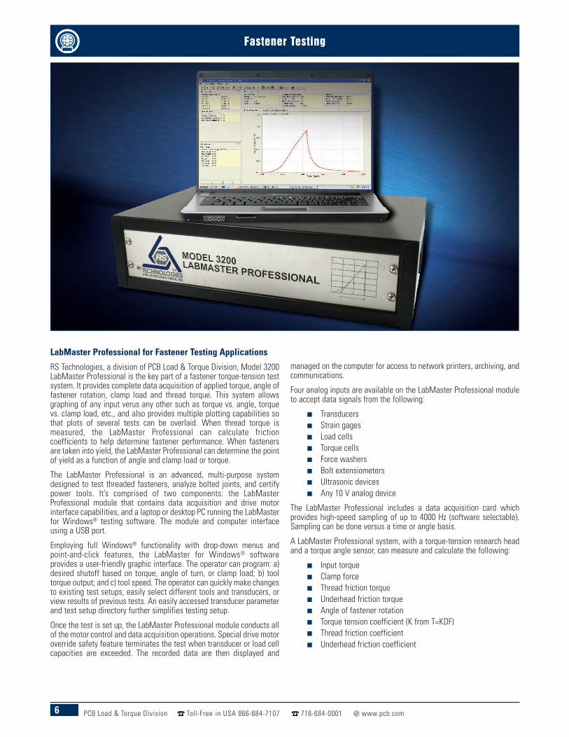
LabMaster Professional for Fastener Testing Applications
RS Technologies, a division of PCB Load & Torque Division, Model 3200LabMaster Professional is the key part of a fastener torque-tension testsystem. It provides complete data acquisition of applied torque, angle offastener rotation, clamp load and thread torque. This system allowsgraphing of any input verus any other such as torque vs. angle, torquevs. clamp load, etc., and also provides multiple plotting capabilities sothat plots of several tests can be overlaid. When thread torque ismeasured, the LabMaster Professional can calculate frictioncoefficients to help determine fastener performance. When fastenersare taken into yield, the LabMaster Professional can determine the pointof yield as a function of angle and clamp load or torque.
The LabMaster Professional is an advanced, multi-purpose systemdesigned to test threaded fasteners, analyze bolted joints, and certifypower tools. It’s comprised of two components: the LabMasterProfessional module that contains data acquisition and drive motorinterface capabilities, and a laptop or desktop PC running the LabMasterfor Windows® testing software. The module and computer interfaceusing a USB port.
Employing full Windows® functionality with drop-down menus andpoint-and-click features, the LabMaster for Windows® softwareprovides a user-friendly graphic interface. The operator can program: a)desired shutoff based on torque, angle of turn, or clamp load; b) tooltorque output; and c) tool speed. The operator can quickly make changesto existing test setups, easily select different tools and transducers, orview results of previous tests. An easily accessed transducer parameterand test setup directory further simplifies testing setup.
Once the test is set up, the LabMaster Professional module conducts allof the motor control and data acquisition operations. Special drive motoroverride safety feature terminates the test when transducer or load cellcapacities are exceeded. The recorded data are then displayed and
managed on the computer for access to network printers, archiving, andcommunications.
Four analog inputs are available on the LabMaster Professional moduleto accept data signals from the following:
n Transducersn Strain gagesn Load cellsn Torque cellsn Force washersn Bolt extensiometersn Ultrasonic devicesn Any 10 V analog device
The LabMaster Professional includes a data acquisition card whichprovides high-speed sampling of up to 4000 Hz (software selectable).Sampling can be done versus a time or angle basis.
A LabMaster Professional system, with a torque-tension research headand a torque angle sensor, can measure and calculate the following:
n Input torquen Clamp forcen Thread friction torquen Underhead friction torquen Angle of fastener rotationn Torque tension coefficient (K from T=KDF)n Thread friction coefficientn Underhead friction coefficient

7PCB Load & Torque Division Toll-Free in USA 866-684-7107 716-684-0001 www.pcb.com
Fastener Testing
The LabMaster organizes the setup by what are called workspaces.Separate workspaces can be created for different part numbers, differentcustomers, different procedures, or whatever makes sense for yourtesting needs. The test setups, numeric limit results, and graphicrundown data for a given workspace are stored and accessible via thatworkspace. All torque transducers, load cells, drive motors, etc., that areset up in the LabMaster can be assigned to testing in any of theworkspaces.
The daily operation of the LabMaster is divided up into three differentperspectives that correspond to most fastener testing routines: setup,test, and plot. In the setup perspective you create new test setups or canedit existing setups. You also can organize and update the transducers,load cells, drive motors, and other devices that are used with theLabMaster. The test perspective is used when actually running the test,displaying a real time plot as the test is being run, and then displaying asecond plot after the test is completed if desired. After the testing iscompleted, the plot perspective is used to construct a wide variety ofplots including multiple plots of recorded graphic data.
The LabMaster uses two basic data storage types. The first is referred toas limit results which is the time and date stamped numeric data for peaktorque, clamp load at peak, angle of rotation from threshold to peaktorque, torque at tension or tension at torque points, etc. After threetests are run and saved, the LabMaster calculates a series of statisticsfor the limit results, including high, median, low, ±3 Sigma, Cpk, etc. Theother data type is graphic or rundown data. This data can be used todisplay the test in a graphic format to show a variety of plots such astorque vs. angle, torque vs. clamp load, thread torque and/or appliedtorque vs. angle, etc. Recorded data can also be exported in an Excel-compatible format for customized reporting or graphing.
The LabMaster Professional also offers a variety of statistical reports innumeric and graphic form. Statistical plots of ±3 Sigma mean curvesprovide an insightful data summary.
The LabMaster Professional and the LabMaster for Windows® testingsoftware provide real-time display during the test. A user-selectableautomatic data save feature for both numeric and graphic data speedstechnician testing time.
After the test is completed, rundown data and plots may be viewed onthe computer display, printed as hard copy, and/or saved for later dataanalysis. Numerous configurable plots can be generated.
A complete torque-tension test system will typically include a rotarytorque-angle transducer, a thread torque-tension research head, a DCelectric tool and controller, and a printer for numeric and graphic datareports, all of which are available from RS Technologies.
Optional features include an auxiliary input for an ultrasonic interface,and a tabletop or mobile test cart.
Setup Summary Screen Real-Time Plot Screen Graphic Data Screen
Model 3200 SpecificationsLabMaster Professional4-channel High-speed Data Acquisition Card
Servo Control Card
Four Inputs for Transducers, Load Cells or Other DevicesUSB Port for Connection to Desktop or Laptop Computer RunningLabMaster for Windows® Software
Analog InputNumber of Channels 4
Signal Conditioning Full Bridge Strain Gage Transducer Compatible
Sensitivity 1 to 4 mV/V, and ±10 VDC
Excitation 10 VDC
Encoder InputNumber of Channels 1
Counter Resolution 32-bit
Input Frequency 1000 kHz Maximum
Excitation 5 VDC
Digital I/OOutputs 7-bits
Inputs 8-bits
Compatibility TTL
Optical Isolation Available
Computer RequirementsWindows® 2000, XP, or 7
2 GB RAM
60 GB Hard Drive
CD-ROM Drive
USB 2.0 Port
Supplied AccessoriesPower Cord, USB Cable, Testing Software Installation Discs, Instruction Manual, & A2LAAccredited Calibration Certificate
Recommended AccessoriesRotary Torque Angle Transducers, Thread Torque Clamp Force Load Cell, DC Drive Motor& Controller, Fixture Assembly, and Portable Test CartBack Panel

8 PCB Load & Torque Division Toll-Free in USA 866-684-7107 716-684-0001 www.pcb.com
Fastener Testing
Portable Data Recorder for Fastener Testing Applications Model 962 Portable Data Recorder is a battery-operated, transientrecorder with two transducer inputs that can be used with torque-only,torque-angle, or force transducers. It can serve as a portable threadedfastener laboratory for measuring fastener torque, angle of turn, andclamp load. Ideal for performing fastener analysis, for auditing andcertifying power tools, and for testing hand torque wrenches; Model962 is a cost effective, versatile, and easy-to-use recorder that cancollect numeric peak data, XY graphic plots, and store on a thumb drive.The data can be easily displayed or printed on a PC running FastPlot2software. The alphanumeric setup and calibration menus assure easeof operation, and the unit can be used with all RS Technologies' rotarytorque-angle and clamp force transducers and other conventional andindustry-standard strain gage transducers.
Model 962 can print out a numeric data report that contains basicinformation about the test along with time & date-stamped data forpeak torque, angle of turn, clamp load, and torque at tension data.Statistics including high, low, median, ±3 Sigma, etc. are calculatedand included on this report. The numeric test data and the graphic datacan be uploaded to a computer via the USB port using the FastPlot2data transfer and plotting utility. FastPlot2 can also provide additionalgraphic analysis.
StatisticsAfter three rundowns, Model 962 Portable Data Recorder updatesstatistics including standard deviation and Cpk. It also flags data asbeing high or low depending upon the programmed engineering limits.
Data and CommunicationsGraphic plots, numeric data reports, and statistics are printed via theparallel port. Recorded data can be downloaded to a PC via the serialport for further analysis using the optional FastPlot2 software. Programupdates are easily uploaded through the USB port.
Real-Time Plotting CapabilitiesModel 962 captures real-time and peak readings for torque-angle,torque-clamp load, or torque-time and immediately displays or plotsone of the following, based upon the instrument setup:
n Torque vs. Timen Torque vs. Anglen Torque & Angle vs. Timen Torque & Clamp Force vs. Timen Torque and Clamp Force vs. Anglen Clamp Force vs. Torquen Tool RPM vs. Timen Tool RPM vs. Angle
Product Features:
n USB Portsn Analog Outputsn Streamlined Menu Systemn Tactile Feel Keypadn Torque or Force Thresholdn External Shunt Calibration Resistors
Portable Data Recorder, Model 962Torque and Force Input ChannelsInput Range ±2.5 mV/V, ±4.5 mV/V, ±5 VDC
Excitation 5 VDC, 120 mA Maximum
Resolution 21-bit
Non-linearity 0.25% Maximum (F.S.)
Frequency Response 10 kHz
Positive Voltage Peak Trap Circuit 7 ms Reset Time
Peak Threshold Software Programmable
Peak Reset Manual or, Software Programmable (Automatic Reset)
Angle Input ChannelType Quadrature A/B Track
Excitation 5 VDC
Input Frequency 1000 kHz Maximum
Display
Viewing Area 4.85 x 2.68 in123 x 68 mm
Resolution 240 x 128 Pixels, Backlit LCD
BatteryIndication Battery Low Indication
Battery Life 8 Hours Maximum, Continuous Use
Charge Time 3.5 Hours, Maximum
General
Temperature Range +32 to +158 °F0 to +70 °C
Dimensions
Size ( W x D x H) 10.12 x 8.50 x 3.25 in257.0 x 215.9 x 85.1 mm
Weight 6.0 lb2700 gm
Mating ConnectorsChannel 1 and Channel 2 DB, 15 Pins
TTL/IO DB, 25 Pins
USB Port A A Type
USB Port B B Type
Supplied AccessoriesFastPlot2 Upload/Graphing Utility for PC Running Windows® 2000, XP, Battery Charger,Serial Cable with USB Adapter, Instruction Manual, Carrying Case, & A2LA AccreditedCalibration Certificate

9PCB Load & Torque Division Toll-Free in USA 866-684-7107 716-684-0001 www.pcb.com
Fastener Testing
Rotary Torque Transducers forFastener Testing ApplicationsSeries PC9000 Rotary TorqueSensors are widely used in thefastener testing market to verify theperformance of threaded fasteners.These durable strain gage-basedtransducers are fitted on the outputdrive of a power tool and measurethe torque applied by the tool to thefastener. This measurementprovides an important part ofdetermining the torque-tensioncharacteristics of a threadedfastener and its coating or plating.
When equipped with an optionalangle encoder, the rotary torquetransducer can also measure theangle of fastener rotation. Torque-angle transducers can provide thedata to draw torque vs. time, torquevs. angle, or torque vs. tension plotsthat are key to the evaluation of athreaded fastener's performance.
SpecificationsTorqueOutput at Rated Capacity 2 mV/V ≤ 0.25% FS
Shunt Calibration Matched 2mV/V ≤ 0.25%with 43.575 kOhm Precision Resistor
Interchangeability Matched for mV/V andShunt Calibration ≤ 0.30% FS
Non-Linearity ≤ 0.25% FSHysteresis ≤ 0.25% FSExcitation Voltage [1] 10 VDCBridge Resistance 350 OhmCompensatedTemperature Range
+70 to +150°F+21 to +66°C
Operating TemperatureRange
0 to +200°F-18 to +93°C
Connector PT02H-12-10P
Angle
Magnetic Encoder
1/4 inch, 3/8 inch and 1/2 inch Drive – 360 Poles3/4 inch Drive – 540 Poles
1 inch and 1-1/2 inch Drive – 720 Poles2-1/2 inch Drives – 900 Poles
Output A-B Track 90 Degrees Phase Difference Flat OverOperating Speed Range
Counts Per Resolution(CPR),Resolution w/Quadrature
1/4 inch, 3/8 inch, 1/2 inch Drive – 1440, 1/4 Degree3/4 inch Drive – 2160, 1/6 Degree
1 inch and 1-1/2 inch Drive – 1/8 Degree2-1/2 inch Drive – 1/10 Degree
Output Voltage High 5.0V to Low 0.5VPower Required 5 VDC @ 120 mA Maximum
Recommended Maximum RPM¼-inch Drive 50003/8-inch Drive 25001/2 -inch Drive 25003/4-inch Drive 20001-inch Drive 10001 1/2 -inch Drive 7502 1/2 -inch Drive 500
Supplied AccessoriesShunt Calibration Resistor, & A2LA Accredited Calibration Certificate
Recommended AccessoriesModel 920 PortableDigital Transducer 080920-01000
Model 962 Data Recorder 080962-01000Cable Assembly, 10'Coiled, PT to DB15 Male 097000-34445
Mating Connector PT06A-12-10S(SR)
Note[1] Calibrated a 10 VDC, usable 5 to 20 VDC or VAC RMS
Torque OnlyModel No. Drive Size Capacity039030-50002 ¼-inch Hex 32 ozf-in (0.2 Nm)039030-50021 ¼-inch Hex 20 lbf-in (2.3 Nm)039025-50051 ¼-inch Square 50 lbf-in (5.7 Nm)039030-50101 ¼-inch Hex 100 lbf-in (11.3 Nm)039025-50101 ¼-inch Square 100 lbf-in (11.3 Nm)039030-51015 ¼-inch Hex 132 lbf-in (15 Nm)039025-51015 ¼-inch Square 132 lbf-in (15 Nm)039037-50022 3/8-inch Square 200 lbf-in (22.6 Nm)039037-50051 3/8-inch Square 50 lbf-ft (68 Nm)039050-50101 ½-inch Square 100 lbf-ft (136 Nm)039050-51201 ½-inch Square 148 lbf-ft (200 Nm)039075-50301 ¾-inch Square 300 lbf-ft (406 Nm)039075-51501 ¾-inch Square 369 lbf-ft (500 Nm)039075-53601 ¾-inch Square 600 lbf-ft (814 Nm)039001-53102 1-inch Square 1000 lbf-ft (1356 Nm)039001-01302 1-inch Square 2213 lbf-ft (3000 Nm)039001-53033 1-inch Square 3000 lbf-ft (4068 Nm)039001-01103 1 ½-in Square 7376 lbf-ft (10,000 Nm)039025-00183 2 ½-in Square 18,000 lbf-ft (24,000 Nm)
Torque-AngleModel No. Drive Size Capacity039230-50002 ¼-inch Hex 32 ozf-in (0.23 Nm)
039230-50021 ¼-inch Hex 20 lbf-in (2.3 Nm)
039225-50051 ¼-inch Square 50 lbf-in (5.7 Nm)
039230-50101 ¼-inch Hex 100 lbf-in (11.3 Nm)
039225-50101 ¼-inch Square 100 lbf-in (11.3 Nm)
039230-51015 ¼-inch Hex 132 lbf-in (15 Nm)
039225-51015 ¼-inch Square 132 lbf-in (15 Nm)
039237-50022 3/8-inch Square 200 lbf-in (22.6 Nm)
039237-50051 3/8-inch Square 50 lbf-ft (68 Nm)
039250-50101 ½-inch Square 100 lbf-ft (136 Nm)
039250-51201 ½-inch Square 148 lbf-ft (200 Nm)
039275-50301 ¾-inch Square 300 lbf-ft (406 Nm)
039275-51501 ¾-inch Square 369 lbf-ft (500 Nm)
039275-53601 ¾-inch Square 600 lbf-ft (814 Nm)
039201-53102 1-inch Square 1000 lbf-ft (1356 Nm)
039201-01302 1-inch Square 2213 lbf-ft (3000 Nm)
039201-53302 1-inch Square 3000 lbf-ft (4068 Nm)
039301-01103 1 ½-in Square 7376 lbf-ft (10,000 Nm)
039625-00183 2 ½-in Square 18,000 lbf-ft (24,000 Nm)
Dimensions (in.)1/4 inchHex
1/4 inchSquare 3/8 inch 1/2 inch 3/4 inch
1 inch 1 inch 1 inch1-1/2 inch 2-1/2 inch
(1000 lbf-ft) (2213 lbf-ft) (3000 lbf-ft)Overall Length 4.25 3.23 3.23 3.23 4.13 4.00 4.42 4.33 5.50 9.48Housing Length 2.30 2.30 2.30 2.30 2.69 2.00 2.42 2.44 2.63 4.62Housing Height 2.00 2.00 2.00 2.00 2.94 3.63 3.63 4.74 4.88 7.25Housing Width 1.50 1.50 1.50 1.50 2.50 3.25 3.25 3.88 4.26 6.50Male Drive Length 0.98 0.29 0.42 0.58 0.84 1.06 1.06 1.12 1.60 2.25

10 PCB Load & Torque Division Toll-Free in USA 866-684-7107 716-684-0001 www.pcb.com
Fastener Testing
Fastener Tension & Fastener Torque TensionLoad Cells for Fastener Testing ApplicationsSeries FT9000 & FTA9000 Fastener Tension andFastener Torque-Tension Load Cells use a full bridgestrain gage design. This complete line of fastenertesting load cells provides a signal proportional to thetension developed in a test fastener when thetightening torque is applied. In addition, the fastenertorque-tension version, also referred to as a researchhead, measures the thread torque (pitch torque plusthread friction torque) at the same time. The tension ortorque-tension output signals from either type of loadcell are read using a conventional strain gage readoutdevice or recorded by a data acquisition system. Theseload cells serve as an integral part of a torque-tensionfastener test system when used with a torque-anglesensor and a suitable data acquisition instrument;Model 962 Portable Data Recorder, Model 3210LabMaster Portable, or Model 3200 LabMasterProfessional, available from RS Technologies, arerecommended.
Series FTA9000
Series FT9000
Common SpecificationsOutput at Rated Capacity 2 mV/V
Non-linearity ±0.2% FS
Overload Capacity 50% FS
Hysteresis ± 0.2% FS
Excitation Voltage [1] ±10 VDC
Bridge Resistance 350 Ohms, Full Bridge, Bonded Strain Gage
Supplied AccessoriesShunt Calibration Resistor, & A2LA Accredited Calibration Certificate
Note
[1] Calibrated at 10 VDC, usable 5 to 20 VDC or VAC RMS
Series FT9000 Fastener Tension Load CellsModel No. Capacity059810-01153 3372 lbf (15 kN)
059810-01253 5620 lbf (25 kN)
059810-01104 22 klbf (100 kN)
059810-01304 67 klbf (300 kN)
059810-01504 112 klbf (500 kN)
Series FTA9000 Fastener Tension Load CellsModel No. Thread Torque Capacity Fastener Tension Capacity059400-01024 15 lbf-ft (20 Nm) 4496 lbf (20 kN)
059500-01044 44 lbf-ft (60 Nm) 8992 lbf (40 kN)
059600-01104 110 lbf-ft (150 Nm) 22 klbf (100 kN)
059625-01304 590 lbf-ft (800 Nm) 67 klbf (300 kN)
059650-01604 1475 lbf-ft (2000 Nm) 135 klbf (600 kN)
059720-01095 2950 lbf-ft (4000 Nm) 202 klbf (900 kN)
059740-01185 5900 lbf-ft (8000 Nm) 405 klbf (1800 kN)
Recommended Accessories
Model No. Description080962-01000 Model 962 Recorder
083210-01000 Model 3210 LabMaster Portable
083200-01000 Model 3200 LabMaster Professional
099404-30610 Cable (Series FT9000)
099404-30566 Cable (Series FTA9000)

11PCB Load & Torque Division Toll-Free in USA 866-684-7107 716-684-0001 www.pcb.com
Fastener Testing
Force Washer Transducer for Fastener Testing ApplicationsSeries FT4000 Force Washer Transducers are miniature load cellsdesigned specifically for measuring fastener clamping forces. Thedesign provides high stiffness in a small package, making these loadcells ideal for static and dynamic measurements on fasteners, orstructural test applications where space limitations exist. Force washertransducers come in a variety of English and Metric sizes.
All transducers are carefully sealed and thoroughly tested prior toshipment. Two hardened steel washers are provided with each unit andshould be mounted on both sides of the transducer to minimize anytransmitted rotational effects or spot loading. Please refer to theillustration below for more information.
Series FT4000 Force Washer Transducers can be used along with rotarytorque or torque-angle torque sensors and a data acquisition instrumentto acquire fastener testing data; Model 962 Portable Data Recorder isrecommended. If fastener clamp load alone is required, Model 920Portable Digital Transducer Instrument can quickly capture and recordthe data.
NOTE: Fastener Force Washers are not designed for use as high-accuracy clamp force measurement devices.
Hardened Beveled Washer
Test BoltHardened Flat Washer
Fastener Force Sensor
Common SpecificationsConstruction Steel Flexure, Aluminum Cover
Output at Rated Capacity 1.5 mV/V Nominal
Overload Capacity 150% FS
Non-linearity ±5.0% FS
Hysteresis ±5.0% FS
Zero Offset ±5.0% FS
Excitation Voltage 10 VDC, Maximum
Bridge Resistance 350 Ohms
Operating Temperature Range 0 to +200 ºF-18 to +93 ºC
Supplied AccessoriesOne Pair Hardened Grounded Washers, Shunt Calibration Resistor, & A2LA AccreditedCalibration Certificate
Recommended AccessoriesConnector, DB15 Male 42220-001250
Strain Relief 42230-003200
Model 920 Portable Digital Transducer Instrument 080920-01000
Model 962 Portable Data Recorder 080962-01000
English SizesModel No. Size Inner Diameter Outer Diameter Height Capacity054103-01252 #10 0.196 in (5.0 mm) 0.682 in (17.3 mm) 0.255 in (6.5 mm) 2500 lbf (11.1 kN)
054104-01502 1/4 inch 0.256 in (6.5 mm) 0.674 in (17.1 mm) 0.255 in (6.5 mm) 5000 lbf (22.2 kN)
054105-01802 5/16 inch 0.319 in (8.1 mm) 0.809 in (20.5 mm) 0.317 in (8.1 mm) 8000 lbf (35.6 kN)
054106-01103 3/8 inch 0.381 in (9.7 mm) 0.842 in (21.3 mm) 0.380 in (9.7 mm) 10 klbf (44.5 kN)
054107-01153 7/16 inch 0.443 in (11.2 mm) 0.943 in (23.9 mm) 0.420 in (10.7 mm) 15 klbf (66.7 kN)
054108-01203 1/2 inch 0.506 in (12.8 mm) 1.111 in 28.2 mm) 0.455 in (11.6 mm) 20 klbf (89.0 kN)
054109-01253 9/16 inch 0.569 in (14.5 mm) 1.213 in (30.8 mm) 0.495 in (12.6 mm) 25 klbf (111.2 kN)
054110-01303 5/8 inch 0.631 in (16.0 mm) 1.348 in (34.2 mm) 0.525 in (13.3 mm) 30 klbf (133.4 kN)
054112-01403 3/4 inch 0.756 in (19.2 mm) 1.618 in (41.1 mm) 0.595 in (15.1 mm) 40 klbf (177.9 kN)
054114-01603 7/8 inch 0.881 in (22.4 mm) 1.888 in (48.0 mm) 0.665 in (16.9 mm) 60 klbf (266.9 kN)
054116-01803 1 inch 1.006 in (25.5 mm) 2.158 in (54.8 mm) 0.735 in (18.7 mm) 80 klbf (355.6 kN)
Metric Sizes054206-01203 M6 6.16 mm (0.243 in) 17.12 mm (0.674 in) 6.48 mm (0.255 in) 20 kN (4496 lbf)
054208-01353 M8 8.16 mm (0.321 in) 20.52 mm (0.808 in) 9.65 mm (0.380 in) 35 kN (7869 lbf)
054210-01543 M10 10.16 mm (0.400 in) 23.95 mm (0.943 in) 10.67 mm (0.420 in) 54 kN (12 klbf)
054212-01084 M12 12.16 mm (0.479 in) 28.22 mm (1.111 in) 11.56 mm (0.455 in) 80 kN (18 klbf)
054214-01114 M14 14.16 mm (0.557 in) 30.81 mm (1.213 in) 12.57 mm (0.495 in) 110 kN (25 klbf)
054216-01144 M16 16.16 mm (0.636 in) 34.24 mm (1.348 in) 13.34 mm (0.525 in) 140 kN (31 klbf)
054218-01184 M18 18.16 mm (0.715 in) 41.14 mm (1.620 in) 15.11 mm (0.595 in) 180 kN (40 klbf)
054220-01224 M20 20.16 mm (0.794 in) 41.14 mm (1.620 in) 15.11 mm (0.595 in) 220 kN (49 klbf)
054222-01274 M22 22.16 mm (0.872 in) 47.95 mm (1.888 in) 16.89 mm (0.665 in) 270 kN (61 klbf)
054224-01324 M24 24.16 mm (0.951 in) 54.86 mm (2.160 in) 18.67 mm (0.735 in) 320 kN (72 klbf)
054230-01404 M30 30.18 mm (1.188 in) 71.45 mm (2.813 in) 25.40 mm (1.000 in) 400 kN (90 klbf)

12 PCB Load & Torque Division Toll-Free in USA 866-684-7107 716-684-0001 www.pcb.com
Fastener Testing
Fastener Drive System for Fastener Testing ApplicationsFastener Drive Systems are available in a variety of speed andtorque configurations, depending upon the size and type offasteners and testing requirements. The systems are comprised ofa rugged, heavy-duty industrial DC brushless electric motor and adependable servo controller that together provides the precise andaccurate torque and speed that is required for threaded fastenertesting. The system can be supplemented with torque multipliers toextend their torque and speed range.
Fastener Drive Systems are used in conjunction with RSTechnologies’ Model 3200, LabMaster Professional, to providecontrol. Model 3200 is an advanced multipurpose system designedto perform automated threaded fastener testing and joint analysis.When the Fastener Drive System is used with the LabMasterProfessional, the unit provides real-time data display as well asprinting, plotting, and automatic data storage capabilities.
A complete test system also includes a rotary torque-angletransducer, a combination tread torque and clamp force transducer,a text fixture assembly for mounting all components, and a printerfor data reports and plots.
Basic Fastener Drive SystemModel No.
Motor Max Speed (RPM) Torque Output08-CLEC-00MTR 165 150 Nm (111 lbf-ft)
08-CLEC-01MTR 125 285 Nm (210 lbf-ft)
08-CLEC-02MTR 55 450 Nm (332 lbf-ft)
Control Unit08-CLEC-0CTRL Controller 110 VAC Power
08-CLEC-1CTRL Controller 220 VAC Power
Cable08-CLEC-0CBLE
Fastener Drive SystemModel No. Capacities
089200-00524 0 to 614 RPM 40 lbf-ft54 Nm
089200-00526 0 to 250 RPM 97 lbf-ft132 Nm
089200-00528 0 to 127 RPM 192 lbf-ft260 Nm
089400-00606 0 to 192 RPM 288 lbf-ft391 Nm
089600-00621 0 to 102 RPM 576 lbf-ft781 Nm
089800-00631 0 to 102 RPM 791 lbf-ft1073 Nm
089120-01000 0 to 74 RPM 1095 lbf-ft1485 Nm
LabMaster test system drive motors areprogrammed for operation using the Lab-master for Windows® testing software.
Basic Fastener Drive Systems are usedwith Model 962 or Model 3210 recordersand are controlled by the operator

13PCB Load & Torque Division Toll-Free in USA 866-684-7107 716-684-0001 www.pcb.com
Fastener Testing
Fixture Assembliesn Measure and record torque, angle, and tension characteristics of
threaded fastenersn Verify threaded fastener torque-angle-tension calculationsn Test actual fasteners in a laboratory environment
A typical Fastener Test Stand for fastener sizes up to M12 (9/16 inch),provides a slide bearing mount for the fastener drive motor and rotarytorque-angle sensor, and stationary mounting for the torque-tensionresearch head. When used with a Model 3200 LabMaster, it is ideal forconducting torque-tension testing on all types of threaded fasteners. TheLabMaster is an advanced multi-purpose system designed to performdynamic threaded fastener testing and joint analysis. It provides real-timedata display as well as printing, plotting, and automatic data storagecapabilities. A complete fastener test system includes a DC electric tooland controller, a rotary torque-angle transducer, a combination threadtorque and clamp force transducer, and a printer for data reports and plots.
The standalone Fastener Test Stand for fastener sizes up to M33 (1-3/8inch), provides sturdy mounting for the fastener drive motor system, rotarytorque-angle sensors, and torque multiplier (if needed) The torque-tensionresearch head or clamp force load cell is mounted on a dual slide assembly.When teamed with a Model 3200 LabMaster data recorder, it is ideal forconducting research on large threaded fasteners. The LabMaster is anadvanced multi-purpose system designed to perform threaded fastenertesting and joint analysis. It provides real-time data display as well asprinting, plotting, and automatic data storage capabilities. A completefastener test system includes a DC electric tool and controller, a rotarytorque-angle transducer, a combination thread torque and clamp forcetransducer, and a printer for data reports and plots.
The Wheel Nut Test Stand, for fastener sizes up to 28 inches in diameter,when teamed with a Model 3200 LabMaster Professional, is ideal forconducting research on automotive and light truck wheels and wheel nuts.It is a complete, automated threaded fastener test stand. The LabMasterrecorder is an advanced multi-purpose system designed to performthreaded fastener testing and joint analysis. It provides real-time datadisplay as well as printing, plotting, and automatic data storage, all in auser-friendly Windows-based interface. A complete wheel nut test systemalso includes a DC electric tool and controller with rotary torque transducer,combination thread torque and clamp force transducer, and a printer fordata reports and graphs.

14 PCB Load & Torque Division Toll-Free in USA 866-684-7107 716-684-0001 www.pcb.com
Fastener Testing
SR1 Bolt Calculation SoftwareA Complete Bolted Joint Design and Analysis package that fits right on yourWindows® desktop.
SR1 Bolt Calculation SoftwareSR1 is a Windows®-based software program that calculates and chartsdata for high-stress, bolted joints. Based on the German Standard VDI2230, SR1 enhances the VDI calculation method with the addition ofseveral other factors including temperature gradients, thread stripcalculations, and M-Alpha and F-Alpha diagrams. It can be used for boltedjoints with concentric or eccentric strain and load. SR1 uses the calculateddata to produce scale drawings of all components of the bolted joint and agraphic representation of several important graphs and diagrams. Thisoutput lets you not only view the assembly from all angles but alsoestimate such important factors as clamp force per degree of rotation, boltstretch, yield point, and several safety factors, such as embedment,loosening, and thread strip.
Who Can Use SR1?Anyone involved in theengineering, design, test,measurement, and control ofthreaded fastener assemblieswill find that the SR1 softwareis a “must have” tool.Practicing engineers, professors, instructors and students will all find thatthe SR1 software is perhaps the best technical guide to engineering,designing, and analyzing bolted joints. With SR1 they can evaluate allprevious designs and, with past experience as a guide, use this informationto assist in creating more reliable new designs.
System RequirementsSR1 will run easily on an IBM-PC compatible computer runningWindows® XP or Windows® 7.
How SR1 is UsedBased on the preliminary input of the amount and type of load, itsapplication, and the tightening method, SR1 calculates and suggestsdifferent combinations of bolt diameters and strength classes.The following is then required:
n Define the bolt and nut by selecting from database or directentry.
n Define the parts that will be clamped together. This includesthe dimensions, material, e-Modulus, and permissible surfacepressure for up to ten clamping pieces.
n Enter the friction coefficients, either from the database or asderived from experimental testing. The most important frictioncoefficients for thread, head seat, and seam are available foruse from the integrated SR1 database.
n Specify the scatter factor of the assembly process. Certaintypes of tooling can introduce a greater amount of scatter thanothers.
From the above inputs, SR1 provides the following outputs:n Numerous charts, graphs and printouts.n Safety Factors such as evaluations for thread strip,
embedment, bolt stretch, etc.n M-Alpha (torque vs. angle) and F-Alpha (clamp force vs. angle)
diagrams. These show torque or clamping force as a functionof angle of turn starting at the elastic origin. The location of theelastic origin is important because the tension in the joint isdirectly proportional to the angle of turn from that point.Correlation of the M-Alpha and F-Alpha diagrams allowsestimations of joint integrity.
n Load extension diagrams for either assembly or workingstatus. These diagrams illustrate the predicted stretch of thebolt and the compression of the parts being clamped.
n Prints summary reports showing forces, loads, tighteningmoments, compliances, and safety factors.

15PCB Load & Torque Division Toll-Free in USA 866-684-7107 716-684-0001 www.pcb.com
Fastener Testing
Accessories for Fastener Testing
Fastener Test System CablesPART NO. DESCRIPTION099404-30610 DB-15P to Bendix 4S, Model 962/Model 3200 to 4-pin Load Cell, 10-ft straight
099404-34011 DB-15P to Bendix 4S, Model 962 to 4-pin Load Cell, 3-ft straight
099404-30563 DB-15P w/Screw Clip to Bendix 10S, Model 962/Model 3200 to Torque-Angle Transducer, 10-ft straight
099504-31843 DB-15P to Bendix 6S, Model 962/Model 3200 to 6-pin Transducer, 10-ft straight
099404-30566 (2) DB-15P to Bendix 10S, Model 3200 to Torque-Tension Load Cell, 10-ft straight
093210-49585 PT-10P to PT-10S, Model 3210 to Torque Angle Transducer, 10-ft straight
093210-49586 PT-10P to PT-10S, Model 3210 to Torque Tension Load Cell, 10-ft straight
093210-49587 PT-10P to PT-4S, Model 3210 to 4 Pin Torque Transducer or Load Cell, 10-ft straight
Fastener Test System AccessoriesPART NO. DESCRIPTION089504-10000 Fastener Test System Printer
099600-30131 Strain Gage Bridge Input Junction Box, for Use with Non-Standard Transducers and Load Cells
086000-31837 Precision Strain Gage Calibrator, for Field Instrument Calibration
102145-00001 Snap-On X-4 Torque Multiplier (240 ft-lb max. input/1,000 ft-lb max. output)
102145-00491 Sweeney 5:1 Industrial Torque Multiplier w/mounting hardware (196 ft-lb max. input/1000 ft-lb max. output)
102145-00492 Sweeney 15:1 Industrial Torque Multiplier w/mounting hardware (162 ft-lb max. input/2200 ft-lb max. output)
Fastener Tension & Fastener Torque-Tension Load Cell Plate Sets
PART NO. DESCRIPTION1000M6-30429 M6 Plate Set
1000M8-30430 M8 Plate Set
100M10-30431 M10 Plate Set
100M12-30432 M12 Plate Set
100M14-30433 M14 Plate Set
100M16-30434 M16 Plate Set
100M18-30435 M18 Plate Set
100M20-30436 M20 Plate Set
100M22-30438 M22 Plate Set
100M25-30437 M25 Plate Set
100M27-30440 M27 Plate Set.
100M30-30443 M30 Plate Set
100008-02000 #8 Plate Set
100010-02000 #10 Plate Set
100250-02000 ¼-inch Plate Set
100313-02000 5/16-inch Plate Set
100375-02000 3/8-inch Plate Set
100438-02000 7/16-inch Plate Set
100500-02000 ½-inch Plate Set
100563-02000 9/16-inch Plate Set
100625-02000 5/8-inch Plate Set
100750-02000 ¾-inch Plate Set
100875-02000 7/8-inch Plate Set
101000-02000 1-inch Plate Set
101125-02000 1 1/8-inch Plate Set
101250-02000 1 ¼-inch Plate Set
101500-02000 1 ½-inch Plate Set
Fastener Test System Test Fixtures & CartPART NO. DESCRIPTION109175-30269 Table Top Slide Assembly for 500 Series Drive Motor (Slide for Motor)
109480-30182 Table Top Slide Assembly for 600 Series Drive Motor (Slide for Test Head)
109480-34033 Table Top Dual Slide Assembly
109480-32436 Medium Free-Standing A-Frame Test Stand, includes Slide Assembly
109483-32025 Large Free-Standing Test Stand, includes Slide Assembly
100135-10000 Portable Tool Cart

The Global Leader in Sensors and InstrumentationFor All Your Applications
Toll-Free in USA 888-258-3222E-mail [email protected]
Toll-Free in USA 800-828-8840E-mail [email protected]
Toll-Free in USA 800-860-4867E-mail [email protected]
Toll-Free in USA 800-959-4464E-mail [email protected]
PCB’s Line of Fastener Test Products (formerly the RS Technologies product line) includes test systems and threaded fastenertorque/angle/tension systems ideal for use in the Automotive, Aerospace & Defense, Power Generation industries, and for productassembly by manufacturers or processors of threaded fasteners or other companies that use threaded fasteners to assemble theirproducts. For more information, please visit www.pcb.com
Fastener Testing
24350 Indoplex Circle, Farmington Hills, MI 48335 USAToll-Free in USA 866-684-7107
24-hour SensorLineSM 716-684-0001 Fax 248-888-8266 E-mail [email protected]
Website www.pcb.comISO 9001 CERTIFIED n A2LA ACCREDITED to ISO 17025
© 2014 PCB Group, Inc. In the interest of constant product improvement, specifications are subject to change withoutnotice. PCB, ICP, Modally Tuned, Spindler, Swiveler and TORKDISC are registered trademarks of PCB Group. SoundTrackLXT, Spark and Blaze are registered trademarks of PCB Piezotronics. SensorLine is a service mark of PCB Group. All othertrademarks are property of their respective owners.
LT-RS-Fastener-Testing-0914 Printed in U.S.A.