fastener components - gammatool · f-1 05/10/07 fastener components index ... acceptable: complete...
TRANSCRIPT

05/10/07
F-1
Assembly
TMFASTENER COMPONENTS
INDEX
PAGE DATE SERIES DESCRIPTION
F-1 05/10/07 Fastener Components Index
F-1.1 05/24/02 Metric Fastener Standards
F-2 05/10/07 Metric Fastener Standards
F-2.1 sdradnatS renetsaF cirteM 99/10/90
F-2.2 seziS renetsaF cirteM derreferP 99/10/90
F-2.3 04/18/07 Fastener Installation and Torquing Procedure
F-2.4 erudecorP tiduA euqroT04/18/07
F-2.5 teehS ataD euqroT 99/10/90
F-3 03/01/99 F01 Socket Head Cap Screw
F-4 08/07/96 F01 Socket Head Cap Screw Coding
F-5 03/01/96 F01 Socket Head Cap Screw Coding
F-6 03/01/99 F02 Low Profile Socket Head Cap Screw
F-7 03/01/96 F02 Low Profile Socket Head Cap Screw Coding
F-8 05/14/97 F03 Socket Flathead Cap Screw
F-9 06/10/98 F03 Socket Flathead Cap Screw Coding
F-10 12/10/97 F04 Socket Head Shoulder Screw
F-11 12/10/97 F04 Socket Head Shoulder Screw Coding
F-11.1 03/01/99 F05 Hex Head Screw (Class 10.9)
F-11.2 03/01/99 F05 Hex Head Screw (Class 10.9) Coding
F-12 09/18/98 F06 Hex Head Screw (Class 12.9)
F-12.1 09/18/98 F06 Hex Head Screw (Class 12.9)
F-13 09/18/98 F06 Hex Head Screw (Class 12.9) Coding
F-13.1 09/18/98 F06 Hex Head Screw (Class 12.9) Coding
F-14 05/14/97 F21, F22, F23 Socket Set Screw
F-15 05/14/97 F21, F22, F23 Socket Set Screw Point Styles
F-16 09/18/98 F39 Hex Nut, Fine Thread (F41 Series Discontinued)
F-17 09/18/98 F42 Hex Nut, Coarse Thread Washer Face
F-18 11/12/97 F45, F47 Hex Jam Nut, Fine Thread/Coarse Thread
F-19 05/14/97 F46, F48 Hex Jam Nut, Fine Thread/Coarse Thread
w/ Washer Face
F-20 09/10/97 F62 Hardened Washer
F-21 09/18/98 F91 Pull Dowel Pin
F-22 04/09/97 F91 Pull Dowel Pin Coding
F-23 )3.2-F ot devom( seziS renetsaF cirteM derreferP 99/10/30
©1997 Auto/Steel Partnership www.naamsstandards.org This document is Uncontrolled when printed.
F-2.6 Fasteners In Non-Ferrous Materials04/18/07

Assembly
TM
GLOBAL STANDARD COMPONENTS
F – 1.1©1997 Auto/Steel Partnership
A Dimensional and Material Specifications
Product Dimensional Specification Material Specification
Socket Head Cap Screws ANSI B18.3.1M ASTM A574M
Hex Head Cap Screws ANSI B18.2.3.1M ASTM F586M, Class 12.9
Base Leveling Screw M24 x 2.0 x 150 HHCS Property Class 10.9
Hex Nuts ANSI B18.2.4.2M ASTM A563M, Class 12
Lock Nuts ANSI B18.16.3M ASTM A563M, Class 12
Hex Jam Nuts ANSI B18.2.4.5M ASTM A563M, Class 04
Shoulder Screws ANSI B18.3.3M ANSI B18.3.3M
Socket Set Screws ANSI B18.3.6M Class 45H
Flat Head Cap Screws ANSI B18.3.5M ASTM F835M
Button Head Cap Screws ANSI B18.3.4M ASTM F835M
PullOut Dowel Pins ISO 8735A —
Flat Washers (M6 – M10) — Rc 38-45 through hardened
(M12 and Larger) ASTM F436M ASTM F436M
Notes:
All specifications must be to the latest revision
All metric fasteners in tooling and sub-assemblies for use in North American automotive facilities must have blue
color identification with characteristics outlined in these standards.
Dimensions apply to fasteners before they are coated.
B Fastener Installation and Assembly Standards
1. All SHCS must be property class 12.9 and must fully conform to ANSI B18.3.1M and ASTM A574M. All prop-
erty class 12.9 HHCS must fully conform to ANSI B18.2.3.1M and ASTM F568M, property class 12.9. If one or
several HHCS are substituted when SHCS are called out within the same bolt pattern, property class 12.9
HHCS must be used. When HHCS only are specified for a bolt pattern, property class 10.9 HHCS may be
specified. All property class 10.9 HHCS must fully conform to ANSI B18.2.3.1M and ASTM F568M, property
class 10.9.
2. All mating nuts for screws specified in item 1 must be property class 12, in accordance with ASTM A563M, and
conform to ANSI B18.2.4.2M. This requirement is in keeping with ASTM guidelines, which recommend that
nuts be strength matched to mating screws.
3. Locking nuts, when specified, must meet requirements of ASTM A563M Class 12, and must be of all metal
type, meeting prevailing torque requirements for class 10 nuts in ANSI B18.16.1M.
4. Nylon patch thread locking elements, when specified, should be applied to screw threads, and must meet pre-
vailing torque requirements listed with these standards.
5. The use of anaerobic adhesives should be limited to applications in which installation torque values must be
low, and where there is little possibility of fastener re-use. Components that might be serviced or adjusted af-
ter they are assembled, including torque auditing by quality control personnel, should not utilize such adhe-
sives.
6. All dowel pins, 6mm and larger in diameter, should be pull type and have an air relief mechanism (machined
flat or spiral groove).
7. Dowel pins 5mm and smaller in diameter may be standard or pull type at supplier’s option.
8. All washers used in assemblies with screws listed in item 1 must be through hardened.
METRIC FASTENERSTANDARDS
05/24/02

Assembly
TM
G L O B A L S TA N D A R D C O M P O N E N T S
F – 2
9. All fasteners except dowel pins and shoulder screws shall be completely and uniformly covered with a blueidentification coating that is readily distinguishable as blue to identify them as metric. Shoulder screws shall becolored on the head only and the coating shall not interfere with full engagement of the drive key. Pull dowelsshall be coated on the untapped end only.
Two methods of applying blue identification coating are acceptable for socket and hex head products. Eachmethod allows different types of acceptable coatings and coverage. These methods shall be adhered to.
Method 1: Coating of the entire fastener. This method of application is intended for coating large quantitiesat a time and proves to be the most cost-effective.
Acceptable: Complete and uniform coverage of entire fastener covered with a blue identification coatingthat is readily distinguishable as blue.
Not Acceptable:1. Coating applied using an electro-deposition process due to the danger of hydrogen embrittlement,
which contributes to premature fastener failure.
2. Paint of ANY nature (urethane, epoxy, acrylic, enamel, latex, etc.) as this will severely degrade thefunctionality of the fastener and will lead to improper installation torque readings resulting in prematurefailure of the joint.
3. Material of ANY nature that would compromise the functionality of the fastener.
4. Material of ANY nature that interferes with the "free running" of a fastener into it's mating element (tap-ping hole or internally threaded element). This does not apply to threads with locking elements.
Method 2: Coating of the fastener head only. This method of application is intended for coating smallquantities at a time (usually at the Distributor level) and may prove to be a time and cost saver.
Acceptable1. Any blue identification coating material that will adhere to the fastener head is acceptable.
Not Acceptable1. Material of any nature in the socket that would interfere with full engagement of the drive key.
2. Coating material of ANY nature on ANY portion of the threads, unless the coating material meets thestandards described in Method 1.
Whether threads are or are not covered with a blue coating, the K factor shall be in the range 0.13 to 0.17
10. Adherence to recommended cutting tools in this standard is mandated in order to achieve proper preloading offasteners. These standards provide for the maximum allowable eccentricity of the longest standard screws andfor certain deviations in the parts being fastened, such as hole straightness, angularity between the axis of thetapped hole and that of the hole for the shank, differences in the center distances of the mating holes andother deviations.
METRIC FASTENERSTANDARDS
05/10/07
A
Blue identification coating shall not be required after January 1, 2008. B
©1997 Auto/Steel Partnership www.naamsstandards.org This document is Uncontrolled when printed.
C
D
F – 2.1
Assembly
TM
©1997 Auto/Steel Partnership
GLOBAL STANDARD COMPONENTS
METRIC FASTENERSTANDARDS
09/01/99
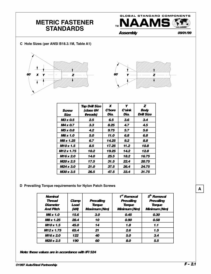
C Hole Sizes (per ANSI B18.3.1M, Table A1)
M3 x 0.5 2.5 6.5 3.6 3.4
M4 x 0.7 3.3 8.25 4.7 4.5
M5 x 0.8 4.2 9.75 5.7 5.6
M6 x 1.0 5.0 11.0 6.8 6.8
M8 x 1.25 6.7 14.25 9.2 8.8
M10 x 1.5 8.5 17.25 11.2 10.8
M12 x 1.75 10.2 19.25 14.2 12.8
M16 x 2.0 14.0 25.5 18.2 16.75
M20 x 2.5 17.5 31.5 22.4 20.75
M24 x 3.0 21.0 37.5 26.4 24.75
M30 x 3.5 26.5 47.5 33.4 31.75
Screw
Size
Tap Drill Size
(class 6H
threads)
X
C'bore
Dia.
Y
C'sink
Dia.
Z
Body
Drill Size
X Y Z60° 60° Y Z
AD Prevailing Torque requirements for Nylon Patch Screws
Note: these values are in accordance with IFI 524
M6 x 1.0 15.6 3.0 0.45 0.30
M8 x 1.25 28.4 10 0.90 0.58
M10 x 1.5 45.0 14 1.8 1.1
M12 x 1.75 65.4 21 2.6 1.5
M16 x 2.0 122 40 5.0 3.4
M20 x 2.5 190 60 8.0 5.5
Nominal
Thread
Diameter
And Pitch
Clamp
Load
(kN)
Prevailing
Torque
Maximum (Nm)
1st Removal
Prevailing
Torque
Minimum (Nm)
5th Removal
Prevailing
Torque
Minimum (Nm)

F – 2.2
Assembly
TM
©1997 Auto/Steel Partnership
GLOBAL STANDARD COMPONENTS
PREFERRED METRICFASTENER SIZES
09/01/99
SOCKET HEAD CAP AND HEX HEAD SCREWS
DOWELS (M6) PULL TYPE
*Socket head cap screws only
**Hex head, leveling screw only
DIAMETER16 20 24 28 32 40 50 60 80
6 X X X
8 X X X X
10 X X X X
12 X X X X
16 X X X
20 X X X
PREFERRED LENGTHS
THREAD CLEARANCESIZE & HOLEPITCH Ø 16 20 30 40 50 60 70 80 150M6 X 1* 6.6 X X X
M8 X 1.25* 9.0 X X X
M10 X 1.5* 11.0 X X X X
M12 X 1.75 13.5 X X X X
M16 X 2 17.5 X X X X
M20 X 2.5 22.0 X X X X
M24 X 2** X
PREFERRED LENGTHS
A

04/18/07
F-2.3
Assembly
TM
FASTENER INSTALLATIONAND TORQUING PROCEDURE
(EXCLUDING SHOULDER SCREWS)
GENERAL• This standard applies only to Property Class 10.9 hex head and 12.9 hex and socket head cap
screws when used in steel, unlubed and where the head bears against a metal surface. Where the
bearing surface is not a metal (e.g. UHMW plastic), the tightening specification for any fastener
shall be “snug fit then 1/4 turn”.
• For purposes of uniformity in clamp loading, the K factor for all metric screws with blue
identification shall be in the range 0.13 to 0.17. Calculations for this standard are based on an
average k value of 0.15.
• Testing by reputable fastener manufacturers has proven that the use of split lockwashers under
heads of hardened screws may prevent achieving or retaining the desired preload in bolted joints.
NominalDiameter
and ThreadPitch
Property Class10.9
M6 x 1.0
M8 x 1.25
M10 x 1.5
M12 x 1.75
M16 x 2.0
M20 x 2.5
M24 x 3.0
12
29
58
100
250
485
840
M30 x 3.5 1670
A
INSTALLATION PROCEDURE1.Use only new fasteners for first-time assembly.
2.Before installing the fastener, be sure that it is free of flaws and it is the correct property class.
Fasteners with flaws shall be marked with a white line drawn across the threads and discarded.
3.Fasteners may be tightened with any appropriate fastening device. Final torquing shall be done
with a calibrated torque wrench to the required value as follows:
Property Class12.9
14
34
68
120
290
570
985
1960
Recommended Installation Torque
4. After torquing is completed, draw a straight line (match mark) from the wall of the fastener head
onto the seating surface using a white steel paint pen. Ensure that the line is easily visible for
periodic inspection.
5. A fastener suspected of being over-torqued shall be marked as described in item 2 and discarded.
6. Do not torque fasteners at machine break points until final installation.
7. Where safety wiring is specified, do not safety wire any screws until they have passed the torque audit.
8. If fasteners are in a position that a torque wrench cannot be used, the following steps shall be used:
a) Tighten the fastener until the joint surfaces have established a snug fit.
b) Mark the position of the fastener to the surface with a white steel paint pen.
c) Tighten the fastener 1/3 of a turn (120).
d) After torquing is completed, draw a straight line (match mark) from the wall of the fastener head
onto the seating surface using a white steel paint pen. Ensure that the line is easily visible for
periodic inspection.
©1997 Auto/Steel Partnership www.naamsstandards.org This document is Uncontrolled when printed.
B
(Nm) For Blue Coated Fasteners
C

F – 2.4
Assembly
TM
G L O B A L S TA N D A R D C O M P O N E N T S
1. Audit samples shall be a random selection consisting of thirty (30) fasteners from each type/size
property class fastener used. Where a sample of thirty is not obtainable, a 100% audit of that
type/size/property class fastener is required.
2. Do not audit at machine break points.
3. Record the applicable torque values from each of the samples on the NAAMS Torque Data Sheet.
4. A fastener shall be deemed to have passed the audit if the torque is within the following limits.
High and low auditing torque limits are ±10% of the recommended installation torque.
TORQUE AUDIT
PROCEDURE04/18/07
5. When a fastener fails the audit:
a. Due to over-torquing: it shall be marked with a white line drawn across the threads and discarded.
b. Due to under-torquing:
i) If the fastener is free of flaws it is suitable for re-use.
ii) When the fastener is flawed, it shall be marked with a white line drawn across the
threads and discarded.
6. When the fastener passes the audit, a straight line (match mark) shall be drawn from the wall of
the fastener head onto the seating surface using a green steel paint pen. Ensure that the line is
easily visible for periodic inspection.
7. When all of the fasteners in the sample pass the audit, the data sheet shall be marked to so indicate.
8. If one of the fasteners in the audit fails the audit:
a. All fasteners of that type/size/property class shall be re-tightened. (Fasteners that passed the
audit may be excluded.)
b. A new sample shall be selected for re-auditing using the criteria in No. 1. However, fasteners
that passed a previous audit shall not be included in the sample for a subsequent audit.
9. Fastener Torque Quality Audit Steps
a. Bench Build Audit: Every unit shall pass the audit before it may leave the bench. Multiple
units may be combined to achieve the sample size of thirty fasteners.
b. Unit-to-Base Audit: Audits shall be performed at periodic stages of the assembly process to
ensure that any possible failures are corrected and passing audits are achieved while
ensuring accessibility to all fasteners.
c. Final Audit: The final audit shall be performed after all engineering changes have been made
and all adjustments are complete.
M6 x 1.0 10.8-13.2 12.6-15.4
M8 x 1.25 26-32 31-38
M10 x 1.5 52-64 61-74
M12 x 1.75 90-110 106-130
M16 x 2.0 225-275 260-320
M20 x 2.5 435-535 515-630
M24 x 3.0 760-930 890-1090
M30 x 3.5 1500-1840 1760-2160
Property Class 10.9
Torque Audit Range (Nm)
Property Class 12.9
Nominal Diameter
and Thread Pitch
• Applies only to screws installed per the NAAMS Fastener Installation and Torquing Procedure.
• The method for checking the fastener torque is the Static Torque Method, which is defined as the
torque required to start a previously tightened fastener into motion in the direction of tightening.
©1997 Auto/Steel Partnership www.naamsstandards.org This document is Uncontrolled when printed.
For Blue Coated Fasteners
B
A

NAAMS FASTENER INSTALLATION AND TORQUING PROCEDURE(EXCLUDING SHOULDER SCREWS)
Torque Data SheetAudit Method: Static
Auditor’s name______________________________________________Date ______________________
Assembly Plant_____________________________Program/System______________________________
Builder/Leader________________________________________Tool # ___________________________
Unit/Station__________________________________________Job # ____________________________
Audit Type: Bench ______ Unit-to-Base ________ Final __________
1 16
2 17
3 18
4 19
5 20
6 21
7 22
8 23
9 24
10 25
11 26
12 27
13 28
14 29
15 30
Pass Fail
10.9 12.9 M____ sh hh
Samp.
#
Torque
Nm
Samp.
#
Torque
Nm
1 16
2 17
3 18
4 19
5 20
6 21
7 22
8 23
9 24
10 25
11 26
12 27
13 28
14 29
15 30
Pass Fail
10.9 12.9 M____ sh hh
Samp.
#
Torque
Nm
Samp.
#
Torque
Nm
Form Date: 09/01/99

Assembly
TM
G L O B A L S TA N D A R D C O M P O N E N T S
F – 2.6
FASTENERS IN NON-
FERROUS MATERIALS 04/18/07
©1997 Auto/Steel Partnership www.naamsstandards.org This document is Uncontrolled when printed.
Thread Torque (Nm) Tapped Material Size Material
F 62 Washer Installation Audit Range
C11000 Yes 31 28 – 34 M8 Steel Wire Yes 37 33 – 41 C11000 Yes 47 42 – 52
Copper C11000 M10 Steel Wire Yes 56 50 – 62
C18000 No 34 31 – 37 M8 C18000 Yes 37 33 – 41 C18000 No 54 49 – 59
Copper C18000 M10 C18000 Yes 56 50 – 62
S304 No 39 35 – 43 M8 S304 Yes 37 33 – 41 S304 No 66 59 – 73
Stainless Steel S304 M10 S304 Yes 56 50 – 62
6060-T6 Yes 37 33 – 41 M8 Steel Wire Yes 37 33 – 41 6060-T6 Yes 56 50 – 62
Aluminum 6061-T6 M10 Steel Wire Yes 56 50 – 62
Installation procedure (page F-2.3) and audit procedure (page F-2.4) are applicable.Data was developed using blue coated fasteners.
Assembly
TM
GLOBAL STANDARD COMPONENTS
F – 3©1997 Auto/Steel Partnership
A
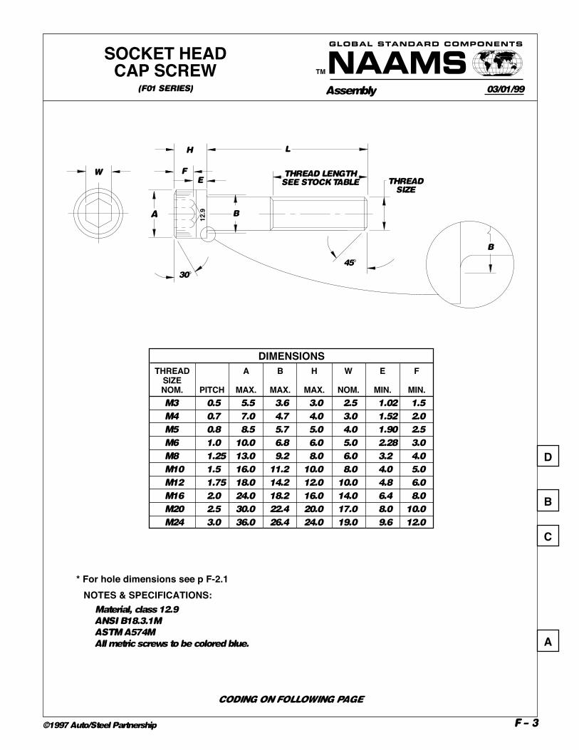
45°
30°
B
L
EF
H
A B
12.9
THREAD LENGTHSEE STOCK TABLE
WTHREAD
SIZE
NOTES & SPECIFICATIONS:Material, class 12.9
ANSI B18.3.1M
ASTM A574M
All metric screws to be colored blue.
SOCKET HEADCAP SCREW
(F01 SERIES)
CODING ON FOLLOWING PAGE
03/01/99
B
C
* For hole dimensions see p F-2.1
DIMENSIONSTHREAD A B H W E F
SIZENOM. PITCH MAX. MAX. MAX. NOM. MIN. MIN.M3 0.5 5.5 3.6 3.0 2.5 1.02 1.5
M4 0.7 7.0 4.7 4.0 3.0 1.52 2.0
M5 0.8 8.5 5.7 5.0 4.0 1.90 2.5
M6 1.0 10.0 6.8 6.0 5.0 2.28 3.0
M8 1.25 13.0 9.2 8.0 6.0 3.2 4.0
M10 1.5 16.0 11.2 10.0 8.0 4.0 5.0
M12 1.75 18.0 14.2 12.0 10.0 4.8 6.0
M16 2.0 24.0 18.2 16.0 14.0 6.4 8.0
M20 2.5 30.0 22.4 20.0 17.0 8.0 10.0
M24 3.0 36.0 26.4 24.0 19.0 9.6 12.0
D

Assembly
TM
GLOBAL STANDARD COMPONENTS
F – 4©1997 Auto/Steel Partnership
THREADSIZENOM.
M3M4M5M6M8
M10M12M16M20M24
5 6 8 10 12 16 20 25 30 35 40 45 50 55 60 65 70 75 80 90 100
110
120
130
140
150
160
170
180
190
200
STOCK SIZES
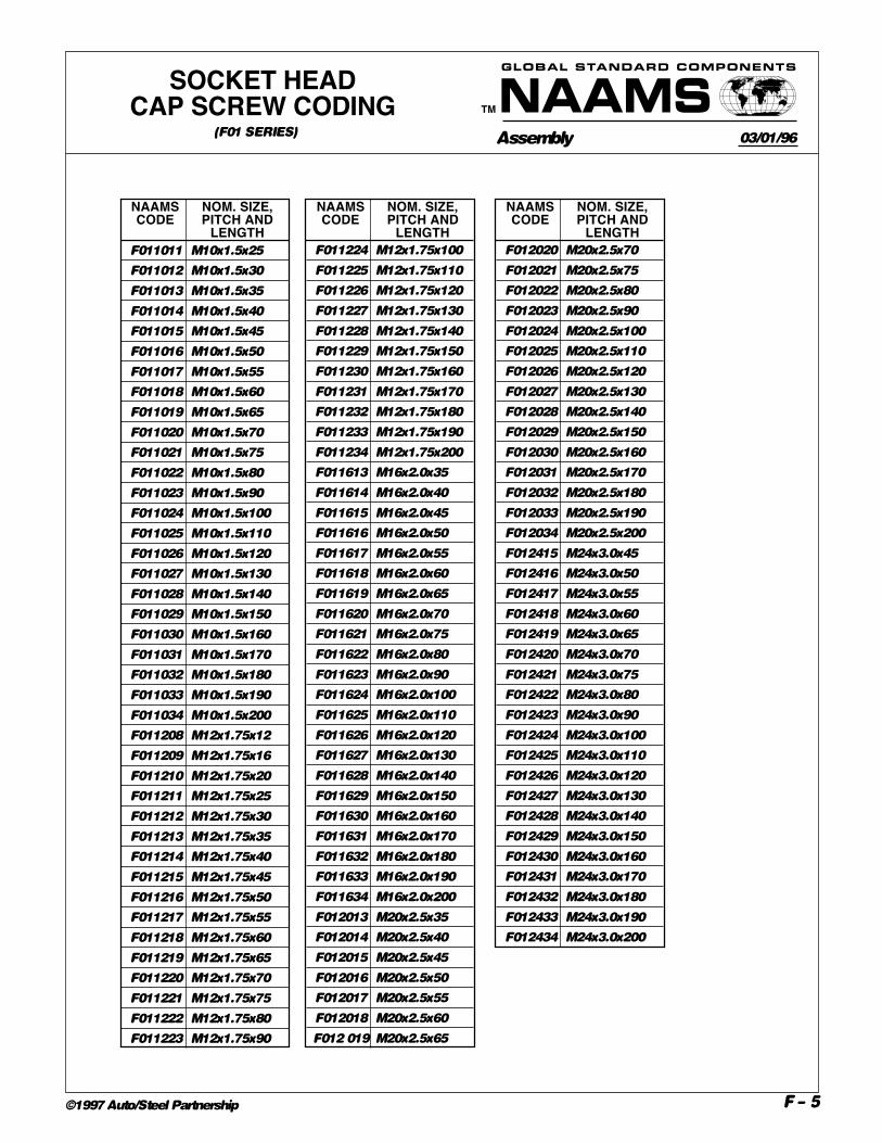
F010304 M3x0.5x5
F010305 M3x0.5x6
F010306 M3x0.5x8
F010307 M3x0.5x10
F010308 M3x0.5x12
F010309 M3x0.5x16
F010310 M3x0.5x20
F010311 M3x0.5x25
F010312 M3x0.5x30
F010313 M3x0.5x35
F010404 M4x0.7x5
F010405 M4x0.7x6
F010406 M4x0.7x8
F010407 M4x0.7x10
F010408 M4x0.7x12
F010409 M4x0.7x16
F010410 M4x0.7x20
F010411 M4x0.7x25
F010412 M4x0.7x30
F010413 M4x0.7x35
F010414 M4x0.7x40
F010415 M4x0.7x45
F010416 M4x0.7x50
NAAMS NOM. SIZE,CODE PITCH AND
LENGTHF010816 M8x1.25x50
F010817 M8x1.25x55
F010818 M8x1.25x60
F010819 M8x1.25x65
F010820 M8x1.25x70
F010821 M8x1.25x75
F010822 M8x1.25x80
F010823 M8x1.25x90
F010824 M8x1.25x100
F010825 M8x1.25x110
F010826 M8x1.25x120
F010827 M8x1.25x130
F010828 M8x1.25x140
F010829 M8x1.25x150
F010830 M8x1.25x160
F010831 M8x1.25x170
F010832 M8x1.25x180
F010833 M8x1.25x190
F010834 M8x1.25x200
F011007 M10x1.5x10
F011008 M10x1.5x12
F011009 M10x1.5x16
F011010 M10x1.5x20
F010505 M5x0.8x6
F010506 M5x0.8x8
F010507 M5x0.8x10
F010508 M5x0.8x12
F010509 M5x0.8x16
F010510 M5x0.8x20
F010511 M5x0.8x25
F010512 M5x0.8x30
F010513 M5x0.8x35
F010514 M5x0.8x40
F010515 M5x0.8x45
F010516 M5x0.8x50
F010517 M5x0.8x55
F010518 M5x0.8x60
F010519 M5x0.8x65
F010520 M5x0.8x70
F010606 M6x1.0x8
F010607 M6x1.0x10
F010608 M6x1.0x12
F010609 M6x1.0x16
F010610 M6x1.0x20
F010611 M6x1.0x25
F010612 M6x1.0x30
NAAMS NOM. SIZE,CODE PITCH AND
LENGTH
NAAMS NOM. SIZE,CODE PITCH AND
LENGTHF010613 M6x1.0x35
F010614 M6x1.0x40
F010615 M6x1.0x45
F010616 M6x1.0x50
F010617 M6x1.0x55
F010618 M6x1.0x60
F010619 M6x1.0x65
F010620 M6x1.0x70
F010621 M6x1.0x75
F010622 M6x1.0x80
F010623 M6x1.0x90
F010624 M6x1.0x100
F010625 M6x1.0x110
F010626 M6x1.0x120
F010807 M8x1.25x10
F010808 M8x1.25x12
F010809 M8x1.25x16
F010810 M8x1.25x20
F010811 M8x1.25x25
F010812 M8x1.25x30
F010813 M8x1.25x35
F010814 M8x1.25x40
F010815 M8x1.25x45
NAAMS NOM. SIZE,CODE PITCH AND
LENGTH
• Lengths to the left of heavy line ( ) threaded to head.
• Lengths to the right of heavy line ( ) have standard minimum thread lengths of two times the nominal
thread diameter plus 12 mm.
(F01 SERIES)
SOCKET HEADCAP SCREW CODING
CODING CONTINUED ON FOLLOWING PAGE
08/07/96
A
Assembly
TM
GLOBAL STANDARD COMPONENTS
F – 5©1997 Auto/Steel Partnership
NAAMS NOM. SIZE,CODE PITCH AND
LENGTHF011011 M10x1.5x25
F011012 M10x1.5x30
F011013 M10x1.5x35
F011014 M10x1.5x40
F011015 M10x1.5x45
F011016 M10x1.5x50
F011017 M10x1.5x55
F011018 M10x1.5x60
F011019 M10x1.5x65
F011020 M10x1.5x70
F011021 M10x1.5x75
F011022 M10x1.5x80
F011023 M10x1.5x90
F011024 M10x1.5x100
F011025 M10x1.5x110
F011026 M10x1.5x120
F011027 M10x1.5x130
F011028 M10x1.5x140
F011029 M10x1.5x150
F011030 M10x1.5x160
F011031 M10x1.5x170
F011032 M10x1.5x180
F011033 M10x1.5x190
F011034 M10x1.5x200
F011208 M12x1.75x12
F011209 M12x1.75x16
F011210 M12x1.75x20
F011211 M12x1.75x25
F011212 M12x1.75x30
F011213 M12x1.75x35
F011214 M12x1.75x40
F011215 M12x1.75x45
F011216 M12x1.75x50
F011217 M12x1.75x55
F011218 M12x1.75x60
F011219 M12x1.75x65
F011220 M12x1.75x70
F011221 M12x1.75x75
F011222 M12x1.75x80
F011223 M12x1.75x90
NAAMS NOM. SIZE,CODE PITCH AND
LENGTHF011224 M12x1.75x100
F011225 M12x1.75x110
F011226 M12x1.75x120
F011227 M12x1.75x130
F011228 M12x1.75x140
F011229 M12x1.75x150
F011230 M12x1.75x160
F011231 M12x1.75x170
F011232 M12x1.75x180
F011233 M12x1.75x190
F011234 M12x1.75x200
F011613 M16x2.0x35
F011614 M16x2.0x40
F011615 M16x2.0x45
F011616 M16x2.0x50
F011617 M16x2.0x55
F011618 M16x2.0x60
F011619 M16x2.0x65
F011620 M16x2.0x70
F011621 M16x2.0x75
F011622 M16x2.0x80
F011623 M16x2.0x90
F011624 M16x2.0x100
F011625 M16x2.0x110
F011626 M16x2.0x120
F011627 M16x2.0x130
F011628 M16x2.0x140
F011629 M16x2.0x150
F011630 M16x2.0x160
F011631 M16x2.0x170
F011632 M16x2.0x180
F011633 M16x2.0x190
F011634 M16x2.0x200
F012013 M20x2.5x35
F012014 M20x2.5x40
F012015 M20x2.5x45
F012016 M20x2.5x50
F012017 M20x2.5x55
F012018 M20x2.5x60
F012 019 M20x2.5x65
NAAMS NOM. SIZE,CODE PITCH AND
LENGTHF012020 M20x2.5x70
F012021 M20x2.5x75
F012022 M20x2.5x80
F012023 M20x2.5x90
F012024 M20x2.5x100
F012025 M20x2.5x110
F012026 M20x2.5x120
F012027 M20x2.5x130
F012028 M20x2.5x140
F012029 M20x2.5x150
F012030 M20x2.5x160
F012031 M20x2.5x170
F012032 M20x2.5x180
F012033 M20x2.5x190
F012034 M20x2.5x200
F012415 M24x3.0x45
F012416 M24x3.0x50
F012417 M24x3.0x55
F012418 M24x3.0x60
F012419 M24x3.0x65
F012420 M24x3.0x70
F012421 M24x3.0x75
F012422 M24x3.0x80
F012423 M24x3.0x90
F012424 M24x3.0x100
F012425 M24x3.0x110
F012426 M24x3.0x120
F012427 M24x3.0x130
F012428 M24x3.0x140
F012429 M24x3.0x150
F012430 M24x3.0x160
F012431 M24x3.0x170
F012432 M24x3.0x180
F012433 M24x3.0x190
F012434 M24x3.0x200
SOCKET HEADCAP SCREW CODING
(F01 SERIES) 03/01/96

Assembly
TM
GLOBAL STANDARD COMPONENTS
F – 6©1997 Auto/Steel Partnership
A
W
B
T
THREADSIZE
45°
LH
C
D
10.9
THREADSIZENOM.
M4M5M6M8M10M12M16M20
STOCK SIZES (L)
8 10 12 16 20 25 30 35 40 45 50 55 60 70 80 90 100
110
120
NOM. A B C D H T WTHREAD
SIZE PITCH MAX MAX MIN MIN MAX MIN NOMM4 0.7 7.0 4 1.06 1.48 2.8 20 3
M5 0.8 8.5 5 1.39 1.85 3.5 22 4
M6 1.0 10.0 6 1.65 2.09 4.0 24 5
M8 1.25 13.0 8 2.24 2.48 5.0 28 6
M10 1.5 16.0 10 2.86 3.36 6.5 32 8
M12 1.75 18.0 12 3.46 4.26 8.0 36 10
M16 2.0 24.0 16 4.91 4.76 10.0 44 12
M20 2.5 30.0 20 6.10 6.07 12.5 52 14
DIMENSIONS
• Lengths to the left of heavy line ( ) threaded to head.
• Lengths to the right of heavy line ( ) have standard minimum thread lengths of two times the nominal
thread diameter plus 12 mm.
NOTES & SPECIFICATIONS:Material, class 10.9
All metric screws to be colored blue.
LOW PROFILE SOCKETHEAD CAP SCREW
(F02 SERIES)
CODING ON FOLLOWING PAGE
A
03/01/99
B
C

Assembly
TM
GLOBAL STANDARD COMPONENTS
F – 7©1997 Auto/Steel Partnership
NAAMS NOM. SIZE,CODE PITCH AND
LENGTHF020406 M4x0.7x8
F020407 M4x0.7x10
F020408 M4x0.7x12
F020409 M4x0.7x16
F020410 M4x0.7x20
F020411 M4x0.7x25
F020412 M4x0.7x30
F020506 M5x0.8x8
F020507 M5x0.8x10
F020508 M5x0.8x12
F020509 M5x0.8x16
F020510 M5x0.8x20
F020511 M5x0.8x25
F020512 M5x0.8x30
F020513 M5x0.8x35
F020514 M5x0.8x40
F020606 M6x1.0x8
F020607 M6x1.0x10
F020608 M6x1.0x12
F020609 M6x1.0x16
F020610 M6x1.0x20
F020611 M6x1.0x25
F020612 M6x1.0x30
F020613 M6x1.0x35
F020614 M6x1.0x40
F020615 M6x1.0x45
F020616 M6x1.0x50
F020617 M6x1.0.55
F020618 M6x1.0x60
F020808 M8x1.25x12
F020809 M8x1.25x16
NAAMS NOM. SIZE,CODE PITCH AND
LENGTHF020810 M8x1.25x20
F020811 M8x1.25x25
F020812 M8x1.25x30
F020813 M8x1.25x35
F020814 M8x1.25x40
F020815 M8x1.25x45
F020816 M8x1.25x50
F020817 M8x1.25.55
F020818 M8x1.25x60
F020820 M8x1.25x70
F021009 M10x1.5x16
F021010 M10x1.5x20
F021011 M10x1.5x25
F021012 M10x1.5x30
F021013 M10x1.5x35
F021014 M10x1.5x40
F021015 M10x1.5x45
F021016 M10x1.5x50
F021017 M10x1.5x55
F021018 M10x1.5x60
F021020 M10x1.5x70
F021022 M10x1.5x80
F021023 M10x1.5x90
F021024 M10x1.5x100
F021210 M12x1.75x20
F021211 M12x1.75x25
F021212 M12x1.75x30
F021213 M12x1.75x35
F021214 M12x1.75x40
F021215 M12x1.75x45
F021216 M12x1.75x50
NAAMS NOM. SIZE,CODE PITCH AND
LENGTHF021217 M12x1.75x55
F021218 M12x1.75x60
F021220 M12x1.75x70
F021222 M12x1.75x80
F021223 M12x1.75x90
F021224 M12x1.75x100
F021612 M16x2.0x30
F021613 M16x2.0x35
F021614 M16x2.0x40
F021615 M16x2.0x45
F021616 M16x2.0x50
F021617 M16x2.0x55
F021618 M16x2.0x60
F021620 M16x2.0x70
F021622 M16x2.0x80
F021623 M16x2.0x90
F021624 M16x2.0x100
F021625 M16x2.0x110
F021626 M16x2.0x120
F022014 M20x2.5x40
F022015 M20x2.5x45
F022016 M20x2.5x50
F022017 M20x2.5x55
F022018 M20x2.5x60
F022020 M20x2.5x70
F022022 M20x2.5x80
F022023 M20x2.5x90
F022024 M20x2.5x100
F022025 M20x2.5x110
F022026 M20x2.5x120
LOW PROFILE SOCKETHEAD CAP SCREW CODING
(F02 SERIES) 03/01/96

Assembly
TM
GLOBAL STANDARD COMPONENTS
F – 8©1997 Auto/Steel Partnership
X Y Z SCREW BODY C'SINK C'SINK
SIZE NOM. DRILL SIZE DEPTH (REF) DIA MINM3 3.4 1.61 6.72
M4 4.5 2.18 8.96
M5 5.6 2.60 11.20
M6 6.8 3.22 13.44
M8 8.8 4.46 17.92
M10 10.8 5.45 22.40
M12 12.8 6.69 26.88
M16 16.75 7.80 33.60
M20 20.75 8.96 40.32
6 8 10 12 16 20 25 30 35 40 45 50 55 60 70 80 90 100
• Lengths to the left of heavy line ( ) threaded to head.
• Lengths to the right of heavy line ( ) have standard minimum thread lengths of two times the nominal
thread diameter plus 12 mm.
NOTES & SPECIFICATIONS:Material, Class 12.9
ANSI B18.3.5M
ASTM F835M
All metric screws to be colored blue.
M3 x 0.5 3.00 2.86 6.72 5.35 1.86 0.30 2.0 1.1 0.25 0.25 0.3
M4 x 0.7 4.00 3.82 8.96 7.80 2.48 0.30 2.5 1.5 0.45 0.35 0.4
M5 x 0.8 5.00 4.82 11.20 9.75 3.10 0.35 3.0 1.9 0.66 0.40 0.5
M6 x 1 6.00 5.82 13.44 11.70 3.72 0.35 4.0 2.2 0.70 0.50 0.6
M8 x 1.25 8.00 7.78 17.92 15.65 4.96 0.40 5.0 3.0 1.16 0.60 0.8
M10 x 1.5 10.00 9.78 22.40 19.50 6.20 0.50 6.0 3.6 1.62 0.80 0.9
M12 x 1.75 12.00 11.73 26.88 23.40 7.44 0.60 8.0 4.3 1.80 0.90 1.2
M16 x 2 16.00 15.73 33.60 23.76 8.80 0.80 10.0 4.8 2.20 1.00 1.5
M20 x 2.5 20.00 19.67 40.32 34.60 10.16 1.00 12.0 5.6 2.20 1.20 1.5
BODYDIAMETER
MAX MIN
HEAD HGT. FILLETEXT.
ABOVE D
DRILLALLOW-
ANCETHEO.SHARP
MAXABS.MIN REF
FLUSH-NESSTOL.
HEX.SOC.SIZE
KEYENGAGE-
MENTWALLTHK.
NOM MIN MIN MAX MAX
D A H J T G F MNOM. SCR.DIA. ANDTHREAD
PITCH
HEAD DIA.
SOCKET FLATHEADCAP SCREW
(F03 SERIES)
CODING CONTINUED ON FOLLOWING PAGE
THREADSIZENOM.
M3M4M5M6M8M10M12M16M20
STOCK SIZES (L)
05/14/97
A
B
C
D
A
A
THEOR. SHARPABSOLUTE MIN.
ROUND ORFLAT
T
MG
HL
DF
THREAD LENGTHSEE STOCK
TABLE
90
+2°- 0°
Y REF
90° Z X
J
ENLARGED VIEW OF HEAD

Assembly
TM
GLOBAL STANDARD COMPONENTS
F – 9©1997 Auto/Steel Partnership
NAAMS NOM. SIZE,CODE PITCH AND
LENGTHF030305 M3x0.5x6
F030306 M3x0.5x8
F030307 M3x0.5x10
F030308 M3x0.5x12
F030309 M3x0.5x16
F030310 M3x0.5x20
F030311 M3x0.5x25
F030312 M3x0.5x30
F030406 M4x0.7x8
F030407 M4x0.7x10
F030408 M4x0.7x12
F030409 M4x0.7x16
F030410 M4x0.7x20
F030411 M4x0.7x25
F030412 M4x0.7x30
F030413 M4x0.7x35
F030414 M4x0.7x40
F030506 M5x0.8x8
F030507 M5x0.8x10
F030508 M5x0.8x12
F030509 M5x0.8x16
F030510 M5x0.8x20
F030511 M5x0.8x25
F030512 M5x0.8x30
F030513 M5x0.8x35
F030514 M5x0.8x40
F030515 M5x0.8x45
F030516 M5x0.8x50
F030606 M6x1.0x8
F030607 M6x1.0x10
F030608 M6x1.0x12
F030609 M6x1.0x16
F030610 M6x1.0x20
F030611 M6x1.0x25
NAAMS NOM. SIZE,CODE PITCH AND
LENGTHF030612 M6x1.0x30
F030613 M6x1.0x35
F030614 M6x1.0x40
F030615 M6x1.0x45
F030616 M6x1.0x50
F030807 M8x1.25x10
F030808 M8x1.25x12
F030809 M8x1.25x16
F030810 M8x1.25x20
F030811 M8x1.25x25
F030812 M8x1.25x30
F030813 M8x1.25x35
F030814 M8x1.25x40
F030815 M8x1.25x45
F030816 M8x1.25x50
F030817 M8x1.25x55
F030818 M8x1.25x60
F030820 M8x1.25x70
F031008 M10x1.5x12
F031009 M10x1.5x16
F031010 M10x1.5x20
F031011 M10x1.5X25
F031012 M10x1.5x30
F031013 M10x1.5x35
F031014 M10x.5x40
F031015 M10x1.5x45
F031016 M10x1.5x50
F031017 M10x1.5x55
F031018 M10x1.5x60
F031020 M10x1.5x70
F031022 M10x1.5x80
F031023 M10x1.5x90
F031024 M10x1.5x100
F031210 M12x1.75x20
NAAMS NOM. SIZE,CODE PITCH AND
LENGTHF031211 M12x1.75x25
F031212 M12x1.75x30
F031213 M12x1.75x35
F031214 M12x1.75x40
F031215 M12x1.75x45
F031216 M12x1.75x50
F031217 M12x1.75x55
F031218 M12x1.75x60
F031220 M12x1.75x70
F031222 M12x1.75x80
F031223 M12x1.75x90
F031224 M12x1.75x100
F031612 M16x2.0x30
F031613 M16x2.0x35
F031614 M16x2.0x40
F031615 M16x2.0x45
F031616 M16x2.0x50
F031617 M16x2.0x55
F031618 M16x2.0x60
F031620 M16x2.0x70
F031622 M16x2.0x80
F031623 M16x2.0x90
F031624 M16x2.0x100
F032013 M20x2.5x35
F032014 M20x2.5x40
F032015 M20x2.5x45
F032016 M20x2.5x50
F032017 M20x2.5x55
F032018 M20x2.5x60
F032020 M20x2.5x70
F032022 M20x2.5x80
F032023 M20x2.5x90
F032024 M20x2.5x100
SOCKET FLATHEADCAP SCREW CODING
(F03 SERIES) 06/10/98
A

Assembly
TM
GLOBAL STANDARD COMPONENTS
F – 10©1997 Auto/Steel Partnership
CODING ON FOLLOWING PAGE
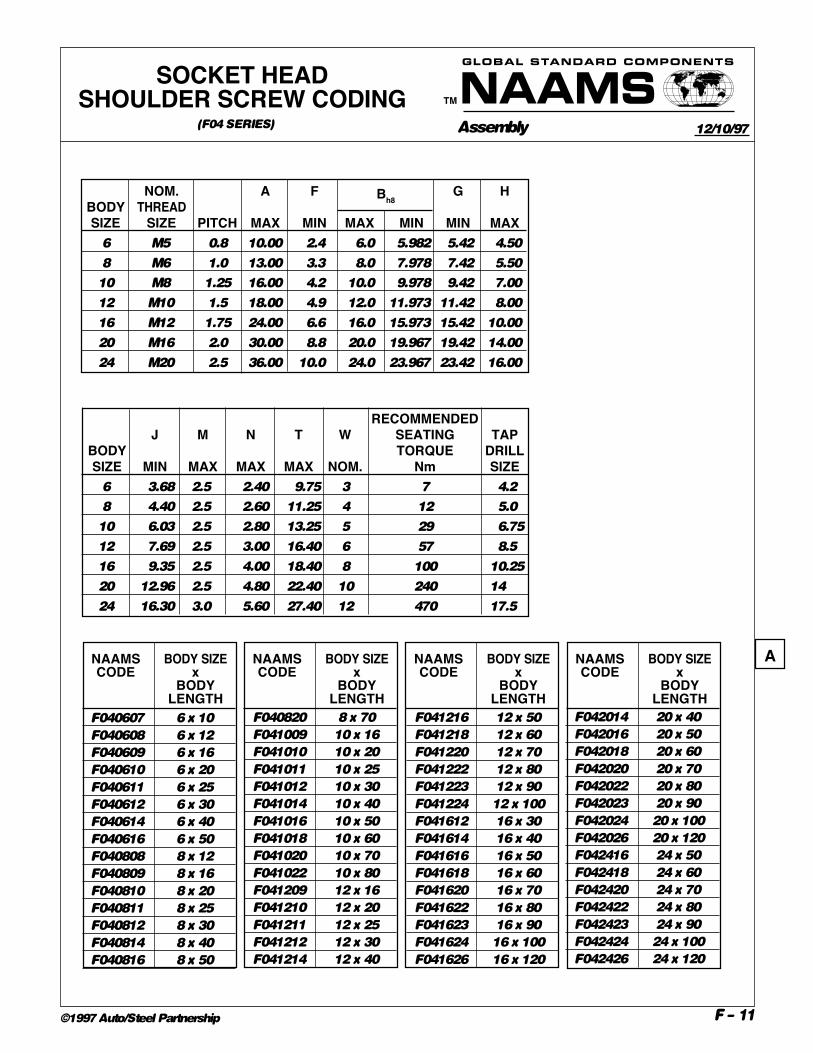
NOTES & SPECIFICATIONS:Material, heat treated alloy steel. Ultimate min. tensile 1100MPa, single shear strength 660MPa.
ANSI B18.3.3M
Screw head only to be colored blue
SOCKET HEADSHOULDER SCREW
(F04 SERIES)
H
F
A
W
30°
G B J
45°
BODYSIZE
T
N
M
HEAD COLORED BLUE
BODYLENGTH
30°
45°
0.8
+0.25- 0.00
THREADSIZE
12/10/97
A
B
STOCK SIZESNOM. BODY LENGTHS
BODY SIZE 10 12 16 20 25 30 40 50 60 70 80 90 100120681012162024 C
Assembly
TM
GLOBAL STANDARD COMPONENTS
F – 11©1997 Auto/Steel Partnership
NOM. A F G HBODY THREADSIZE SIZE PITCH MAX MIN MAX MIN MIN MAX
6 M5 0.8 10.00 2.4 6.0 5.982 5.42 4.50
8 M6 1.0 13.00 3.3 8.0 7.978 7.42 5.50
10 M8 1.25 16.00 4.2 10.0 9.978 9.42 7.00
12 M10 1.5 18.00 4.9 12.0 11.973 11.42 8.00
16 M12 1.75 24.00 6.6 16.0 15.973 15.42 10.00
20 M16 2.0 30.00 8.8 20.0 19.967 19.42 14.00
24 M20 2.5 36.00 10.0 24.0 23.967 23.42 16.00
RECOMMENDEDJ M N T W SEATING TAP
BODY TORQUE DRILLSIZE MIN MAX MAX MAX NOM. Nm SIZE
6 3.68 2.5 2.40 9.75 3 7 4.2
8 4.40 2.5 2.60 11.25 4 12 5.0
10 6.03 2.5 2.80 13.25 5 29 6.75
12 7.69 2.5 3.00 16.40 6 57 8.5
16 9.35 2.5 4.00 18.40 8 100 10.25
20 12.96 2.5 4.80 22.40 10 240 14
24 16.30 3.0 5.60 27.40 12 470 17.5
Bh8
SOCKET HEADSHOULDER SCREW CODING
(F04 SERIES) 12/10/97
F042014 20 x 40
F042016 20 x 50
F042018 20 x 60
F042020 20 x 70
F042022 20 x 80
F042023 20 x 90
F042024 20 x 100
F042026 20 x 120
F042416 24 x 50
F042418 24 x 60
F042420 24 x 70
F042422 24 x 80
F042423 24 x 90
F042424 24 x 100
F042426 24 x 120
F040607 6 x 10
F040608 6 x 12
F040609 6 x 16
F040610 6 x 20
F040611 6 x 25
F040612 6 x 30
F040614 6 x 40
F040616 6 x 50
F040808 8 x 12
F040809 8 x 16
F040810 8 x 20
F040811 8 x 25
F040812 8 x 30
F040814 8 x 40
F040816 8 x 50
F040820 8 x 70
F041009 10 x 16
F041010 10 x 20
F041011 10 x 25
F041012 10 x 30
F041014 10 x 40
F041016 10 x 50
F041018 10 x 60
F041020 10 x 70
F041022 10 x 80
F041209 12 x 16
F041210 12 x 20
F041211 12 x 25
F041212 12 x 30
F041214 12 x 40
F041216 12 x 50
F041218 12 x 60
F041220 12 x 70
F041222 12 x 80
F041223 12 x 90
F041224 12 x 100
F041612 16 x 30
F041614 16 x 40
F041616 16 x 50
F041618 16 x 60
F041620 16 x 70
F041622 16 x 80
F041623 16 x 90
F041624 16 x 100
F041626 16 x 120
NAAMS BODY SIZECODE x
BODYLENGTH
NAAMS BODY SIZECODE x
BODYLENGTH
NAAMS BODY SIZECODE x
BODYLENGTH
NAAMS BODY SIZECODE x
BODYLENGTH
A
GLOBAL STANDARD COMPONENTS
F – 11.1
Assembly
TM
©1997 Auto/Steel Partnership
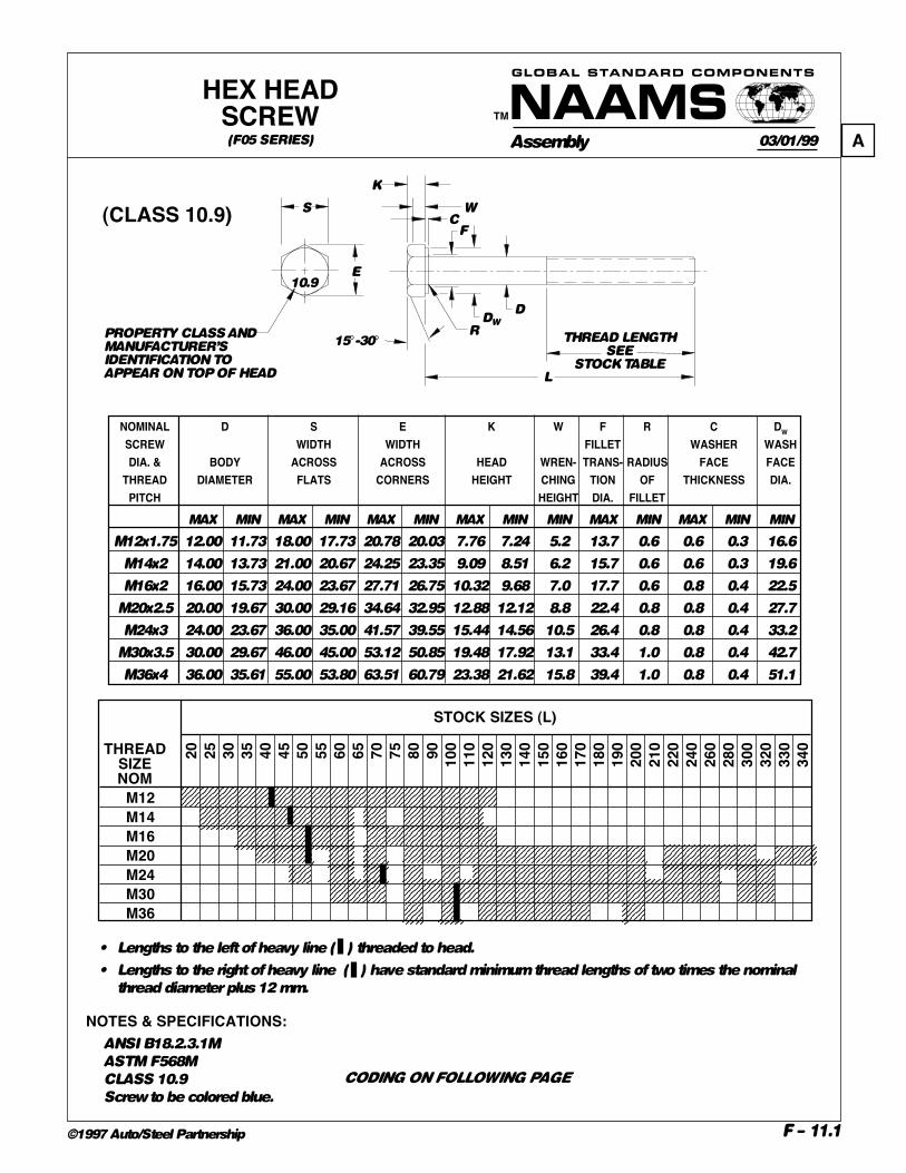
HEX HEADSCREW
03/01/99
(CLASS 10.9)
CODING ON FOLLOWING PAGE
(F05 SERIES)
NOTES & SPECIFICATIONS:ANSI B18.2.3.1M
ASTM F568M
CLASS 10.9
Screw to be colored blue.
• Lengths to the left of heavy line ( ) threaded to head.
• Lengths to the right of heavy line ( ) have standard minimum thread lengths of two times the nominal
thread diameter plus 12 mm.
NOMINAL D S E K W F R C DW
SCREW WIDTH WIDTH FILLET WASHER WASHDIA. & BODY ACROSS ACROSS HEAD WREN- TRANS- RADIUS FACE FACE
THREAD DIAMETER FLATS CORNERS HEIGHT CHING TION OF THICKNESS DIA.PITCH HEIGHT DIA. FILLET
MAX MIN MAX MIN MAX MIN MAX MIN MIN MAX MIN MAX MIN MIN
M12x1.75 12.00 11.73 18.00 17.73 20.78 20.03 7.76 7.24 5.2 13.7 0.6 0.6 0.3 16.6
M14x2 14.00 13.73 21.00 20.67 24.25 23.35 9.09 8.51 6.2 15.7 0.6 0.6 0.3 19.6
M16x2 16.00 15.73 24.00 23.67 27.71 26.75 10.32 9.68 7.0 17.7 0.6 0.8 0.4 22.5
M20x2.5 20.00 19.67 30.00 29.16 34.64 32.95 12.88 12.12 8.8 22.4 0.8 0.8 0.4 27.7
M24x3 24.00 23.67 36.00 35.00 41.57 39.55 15.44 14.56 10.5 26.4 0.8 0.8 0.4 33.2
M30x3.5 30.00 29.67 46.00 45.00 53.12 50.85 19.48 17.92 13.1 33.4 1.0 0.8 0.4 42.7
M36x4 36.00 35.61 55.00 53.80 63.51 60.79 23.38 21.62 15.8 39.4 1.0 0.8 0.4 51.1
20 25 30 35 40 45 50 55 60 65 70 75 80 90 100
110
120
130
140
150
160
170
180
190
200
210
220
240
260
280
300
320
330
340
STOCK SIZES (L)
THREADSIZENOM
M12M14M16M20M24M30M36
F
R
D
THREAD LENGTHSEE
STOCK TABLEL
15°-30°
S
10.9E
PROPERTY CLASS ANDMANUFACTURER’SIDENTIFICATION TOAPPEAR ON TOP OF HEAD
K
W
DW
C
A

GLOBAL STANDARD COMPONENTS
F – 11.2
Assembly
TM
©1997 Auto/Steel Partnership
HEX HEADSCREW CODING
03/01/99
(CLASS 10.9)NAAMS NOM. SIZE,CODE PITCH AND
LENGTHF051210 M12-1.75 x 20
F051211 M12-1.75 x 25
F051212 M12-1.75 x 30
F051213 M12-1.75 x 35
F051214 M12-1.75 x 40
F051215 M12-1.75 x 45
F051216 M12-1.75 x 50
F051217 M12-1.75 x 55
F051218 M12-1.75 x 60
F051219 M12-1.75 x 65
F051220 M12-1.75 x 70
F051221 M12-1.75 x 75
F051222 M12-1.75 x 80
F051223 M12-1.75 x 90
F051224 M12-1.75 x 100
F051225 M12-1.75 x 110
F051226 M12-1.75 x 120
F051411 M14-2.0 x 25
F051412 M14-2.0 x 30
F051413 M14-2.0 x 35
F051414 M14-2.0 x 40
F051415 M14-2.0 x 45
F051416 M14-2.0 x 50
F051417 M14-2.0 x 55
F051418 M14-2.0 x 60
F051420 M14-2.0 x 70
F051422 M14-2.0 x 80
F051423 M14-2.0 x 90
F051424 M14-2.0 x 100
F051425 M14-2.0 x 110
F051613 M16-2.0 x 35
F051614 M16-2.0 x 40
F051615 M16-2.0 x 45
F051616 M16-2.0 x 50
F051617 M16-2.0 x 55
F051618 M16-2.0 x 60
F051620 M16-2.0 x 70
F051621 M16-2.0 x 75
F051622 M16-2.0 x 80
F051623 M16-2.0 x 90
F051624 M16-2.0 x 100
NAAMS NOM. SIZE,CODE PITCH AND
LENGTHF051625 M16-2.0 x 110
F051626 M16-2.0 x 120
F052014 M20-2.5 x 40
F052015 M20-2.5 x 45
F052016 M20-2.5 x 50
F052018 M20-2.5 x 60
F052020 M20-2.5 x 70
F052022 M20-2.5 x 80
F052023 M20-2.5 x 90
F052024 M20-2.5 x 100
F052025 M20-2.5 x 110
F052026 M20-2.5x 120
F052027 M20-2.5 x 130
F052028 M20-2.5 x 140
F052029 M20-2.5 x 150
F052030 M20-2.5 x 160
F052031 M20-2.5 x 170
F052032 M20-2.5 x 180
F052033 M20-2.5 x 190
F052034 M20-2.5 x 200
F052036 M20-2.5 x 220
F052037 M20-2.5x 240
F052038 M20-2.5 x 260
F052039 M20-2.5 x 280
F052040 M20-2.5 x 300
F052043 M20-2.5x 340
F052416 M24-3.0 x 50
F052418 M24-3.0 x 60
F052420 M24-3.0 x 70
F052422 M24-3.0 x 80
F052424 M24-3.0 x 100
F052425 M24-3.0 x 110
F052426 M24-3.0x 120
F052427 M24-3.0 x 130
F052428 M24-3.0 x 140
F052429 M24-3.0x 150
F052430 M24-3.0 x 160
F052431 M24-3.0 x 170
F052432 M24-3.0 x 180
F052433 M24-3.0 x 190
F052434 M24-3.0 x 200
NAAMS NOM. SIZE,CODE PITCH AND
LENGTHF052436 M24-3.0 x 220
F052437 M24-3.0 x 240
F052438 M24-3.0 x 260
F052439 M24-3.0 x 280
F052440 M24-3.0 x 300
F052442 M24-2.0 x 330
F052443 M24-3.0 x 340
F053018 M30-3.5 x 60
F053019 M30-3.5 x 65
F053020 M30-3.5 x 70
F053022 M30-3.5 x 80
F053023 M30-3.5 x 90
F053024 M30-3.5 x 100
F053025 M30-3.5 x 110
F053026 M30-3.5x 120
F053027 M30-3.5 x 130
F053028 M30-3.5x 140
F053029 M30-3.5x 150
F053030 M30-3.5 x 160
F053031 M30-3.5 x 170
F053032 M30-3.5 x 180
F053033 M30-3.5 x 190
F053034 M30-3.5 x 200
F053035 M30-3.5 x 210
F053036 M30-3.5 x 220
F053037 M30-3.5 x 240
F053038 M30-3.5 x 260
F053040 M30-3.5 x 300
F053041 M30-3.5 x 320
F053622 M36-4.0 x 80
F053623 M36-4.0 x 90
F053624 M36-4.0 x 100
F053626 M36-4.0 x 120
F053627 M36-4.0 x 130
F053628 M36-4.0 x 140
F053629 M36-4.0 x 150
F053630 M36-4.0 x 160
F053631 M36-4.0 x 170
F053634 M36-4.0 x 200
(F05 SERIES) A

Assembly
TM
GLOBAL STANDARD COMPONENTS
F – 12©1997 Auto/Steel Partnership
(CLASS 12.9)F
R
D
THREAD LENGTHSEE
STOCK TABLEL
15°-30°
S
12.9E
PROPERTY CLASS ANDMANUFACTURER’SIDENTIFICATION TOAPPEAR ON TOP OF HEAD
K
W
DW
C
HEX HEADSCREW(F06 SERIES) 09/18/98
B
C
E
NOMINAL D S E K W F R C DW
SCREW WIDTH WIDTH FILLET WASHER WASHDIA. & BODY ACROSS ACROSS HEAD WREN- TRANS- RADIUS FACE FACE
THREAD DIAMETER FLATS CORNERS HEIGHT CHING TION OF THICKNESS DIA.PITCH HEIGHT DIA. FILLET
MAX MIN MAX MIN MAX MIN MAX MIN MIN MAX MIN MAX MIN MIN
M6x1 6.00 5.82 10.00 9.78 11.55 11.05 4.15 3.85 2.8 6.8 0.3 0.5 0.2 8.9
M8x1.25 8.00 7.78 13.00 12.73 15.01 14.38 5.50 5.10 3.7 9.2 0.4 0.6 0.3 11.6
M10x1.5 10.00 9.78 16.00 15.73 18.48 17.77 6.63 6.17 4.5 11.2 0.4 0.6 0.3 14.6
M12x1.75 12.00 11.73 18.00 17.73 20.78 20.03 7.76 7.24 5.2 13.7 0.6 0.6 0.3 16.6
M14x2 14.00 13.73 21.00 20.67 24.25 23.35 9.09 8.51 6.2 15.7 0.6 0.6 0.3 19.6
M16x2 16.00 15.73 24.00 23.67 27.71 26.75 10.32 9.68 7.0 17.7 0.6 0.8 0.4 22.5
M20x2.5 20.00 19.67 30.00 29.16 34.64 32.95 12.88 12.12 8.8 22.4 0.8 0.8 0.4 27.7
M24x3 24.00 23.67 36.00 35.00 41.57 39.55 15.44 14.56 10.5 26.4 0.8 0.8 0.4 33.2
M30x3.5 30.00 29.67 46.00 45.00 53.12 50.85 19.48 17.92 13.1 33.4 1.0 0.8 0.4 42.7
M36x4 36.00 35.61 55.00 53.80 63.51 60.79 23.38 21.62 15.8 39.4 1.0 0.8 0.4 51.1
CONTINUED ON FOLLOWING PAGE

GLOBAL STANDARD COMPONENTS
Assembly
TM
©1997 Auto/Steel Partnership
NOTES & SPECIFICATIONS:ANSI B18.2.3.1M
ASTM F568M
CLASS 12.9
Screw to be colored blue.
HEX HEADSCREW
(F06 SERIES CONTINUED)
• Lengths to the left of heavy line ( ) threaded to head.
• Lengths to the right of heavy line ( ) have standard minimum thread lengths of two times the nominal
thread diameter plus 12 mm.
CODING ON FOLLOWING PAGE
A
D
20 25 30 35 40 45 50 55 60 65 70 75 80 90 100
110
120
130
140
150
160
170
180
190
200
210
220
240
260
280
300
320
330
340
STOCK SIZES
THREADSIZENOM
M12M14M16M20M24M30M36
09/18/98
(CLASS 12.9 CONTINUED)
STOCK SIZES
THREADSIZENOM
M6M8M10
10 12 16 20 25 30 35 40 45 50 55 60 65 70 75 80 85 90 100
110
120
130
140
150
160
180
200
E
F - 12.1

Assembly
TM
GLOBAL STANDARD COMPONENTS
F – 13©1997 Auto/Steel Partnership
(CLASS 12.9)
HEX HEADSCREW CODING
(F06 SERIES) 09/18/98
NAAMS NOM. SIZE,CODE PITCH AND
LENGTHF061010 M10-1.5 x 20
F061011 M10-1.5 x 25
F061012 M10-1.5 x 30
F061013 M10-1.5 x 35
F061014 M10-1.5 x 40
F061015 M10-1.5 x 45
F061016 M10-1.5 x 50
F061017 M10-1.5 x 55
F061018 M10-1.5 x 60
F061019 M10-1.5 x 65
F061020 M10-1.5 x 70
F061021 M10-1.5 x 75
F061022 M10-1.5 x 80
F061023 M10-1.5 x 85
F061024 M10-1.5 x 90
F061025 M10-1.5 x 100
F061026 M10-1.5 x 110
F061027 M10-1.5 x 120
F061028 M10-1.5 x 130
F061029 M10-1.5 x 140
F061030 M10-1.5 x 150
F061031 M10-1.5 x 160
F061032 M10-1.5 x 180
F061033 M10-1.5 x 200
NAAMS NOM. SIZE,CODE PITCH AND
LENGTHF060610 M6-1 x 10
F060611 M6-1 x 12
F060612 M6-1 x 16
F060613 M6-1 x 20
F060614 M6-1 x 25
F060615 M6-1 x 30
F060616 M6-1 x 35
F060617 M6-1 x 40
F060618 M6-1 x 45
F060619 M6-1 x 50
F060620 M6-1 x 55
F060621 M6-1 x 60
F060622 M6-1 x 65
F060623 M6-1 x 70
F060624 M6-1 x 75
F060625 M6-1 x 80
F060810 M8-1.25 x 12
F060811 M8-1.25 x 16
F060812 M8-1.25 x 20
F060813 M8-1.25 x 25
F060814 M8-1.25 x 30
F060815 M8-1.25 x 35
F060816 M8-1.25 x 40
F060817 M8-1.25 x 45
F060818 M8-1.25 x 50
F060819 M8-1.25 x 55
F060820 M8-1.25 x 60
F060821 M8-1.25 x 65
F060822 M8-1.25 x 70
F060823 M8-1.25 x 75
F060824 M8-1.25 x 80
CONTINUED ON FOLLOWING PAGE
B

GLOBAL STANDARD COMPONENTS
Assembly
TM
©1997 Auto/Steel Partnership F - 13.1
(CLASS 12.9 CONTINUED)NAAMS NOM. SIZE,CODE PITCH AND
LENGTHF061210 M12-1.75 x 20
F061211 M12-1.75 x 25
F061212 M12-1.75 x 30
F061213 M12-1.75 x 35
F061214 M12-1.75 x 40
F061215 M12-1.75 x 45
F061216 M12-1.75 x 50
F061217 M12-1.75 x 55
F061218 M12-1.75 x 60
F061219 M12-1.75 x 65
F061220 M12-1.75 x 70
F061221 M12-1.75 x 75
F061222 M12-1.75 x 80
F061223 M12-1.75 x 90
F061224 M12-1.75 x 100
F061225 M12-1.75 x 110
F061226 M12-1.75 x 120
F061411 M14-2.0 x 25
F061412 M14-2.0 x 30
F061413 M14-2.0 x 35
F061414 M14-2.0 x 40
F061415 M14-2.0 x 45
F061416 M14-2.0 x 50
F061417 M14-2.0 x 55
F061418 M14-2.0 x 60
F061420 M14-2.0 x 70
F061422 M14-2.0 x 80
F061423 M14-2.0 x 90
F061424 M14-2.0 x 100
F061425 M14-2.0 x 110
F061613 M16-2.0 x 35
F061614 M16-2.0 x 40
F061615 M16-2.0 x 45
F061616 M16-2.0 x 50
F061617 M16-2.0 x 55
F061618 M16-2.0 x 60
F061620 M16-2.0 x 70
F061621 M16-2.0 x 75
F061622 M16-2.0 x 80
F061623 M16-2.0 x 90
F061624 M16-2.0 x 100
NAAMS NOM. SIZE,CODE PITCH AND
LENGTHF061625 M16-2.0 x 110
F061626 M16-2.0 x 120
F062014 M20-2.5 x 40
F062015 M20-2.5 x 45
F062016 M20-2.5 x 50
F062018 M20-2.5 x 60
F062020 M20-2.5 x 70
F062022 M20-2.5 x 80
F062023 M20-2.5 x 90
F062024 M20-2.5 x 100
F062025 M20-2.5 x 110
F062026 M20-2.5x 120
F062027 M20-2.5 x 130
F062028 M20-2.5 x 140
F062029 M20-2.5 x 150
F062030 M20-2.5 x 160
F062031 M20-2.5 x 170
F062032 M20-2.5 x 180
F062033 M20-2.5 x 190
F062034 M20-2.5 x 200
F062036 M20-2.5 x 220
F062037 M20-2.5x 240
F062038 M20-2.5 x 260
F062039 M20-2.5 x 280
F062040 M20-2.5 x 300
F062043 M20-2.5x 340
F062416 M24-3.0 x 50
F062418 M24-3.0 x 60
F062420 M24-3.0 x 70
F062422 M24-3.0 x 80
F062424 M24-3.0 x 100
F062425 M24-3.0 x 110
F062426 M24-3.0x 120
F062427 M24-3.0 x 130
F062428 M24-3.0 x 140
F062429 M24-3.0x 150
F062430 M24-3.0 x 160
F062431 M24-3.0 x 170
F062432 M24-3.0 x 180
F062433 M24-3.0 x 190
F062434 M24-3.0 x 200
NAAMS NOM. SIZE,CODE PITCH AND
LENGTHF062436 M24-3.0 x 220
F062437 M24-3.0 x 240
F062438 M24-3.0 x 260
F062439 M24-3.0 x 280
F062440 M24-3.0 x 300
F062442 M24-2.0 x 330
F062443 M24-3.0 x 340
F063018 M30-3.5 x 60
F063019 M30-3.5 x 65
F063020 M30-3.5 x 70
F063022 M30-3.5 x 80
F063023 M30-3.5 x 90
F063024 M30-3.5 x 100
F063025 M30-3.5 x 110
F063026 M30-3.5x 120
F063027 M30-3.5 x 130
F063028 M30-3.5x 140
F063029 M30-3.5x 150
F063030 M30-3.5 x 160
F063031 M30-3.5 x 170
F063032 M30-3.5 x 180
F063033 M30-3.5 x 190
F063034 M30-3.5 x 200
F063035 M30-3.5 x 210
F063036 M30-3.5 x 220
F063037 M30-3.5 x 240
F063038 M30-3.5 x 260
F063040 M30-3.5 x 300
F063041 M30-3.5 x 320
F063622 M36-4.0 x 80
F063623 M36-4.0 x 90
F063624 M36-4.0 x 100
F063626 M36-4.0 x 120
F063627 M36-4.0 x 130
F063628 M36-4.0 x 140
F063629 M36-4.0 x 150
F063630 M36-4.0 x 160
F063631 M36-4.0 x 170
F063634 M36-4.0 x 200
HEX HEADSCREW CODING
(F06 SERIES CONTINUED) 09/18/98
A
B

Assembly
TM
GLOBAL STANDARD COMPONENTS
F – 14©1997 Auto/Steel Partnership
35°MAX
T T
LD
J
NAAMS NAAMS NAAMS D J L TCODE CODE CODE NOMINAL HEXAGON NOMINAL FOR CUP
SIZE OF SOCKET SCREW AND FLATFLAT POINT CONE POINT CUP POINT BASIC SIZE LENGTHS POINTS
STYLE STYLE (TYPE 1) SCREW øSTYLE x PITCH NOM. MIN
F210503 F220503 F230503 3 1.2
F210504 F220504 F230504 4 2.0
F210505 F220505 F230505 5 x 0.8 2.5 5 2.7
F210506 F220506 F230506 6 2.7
F210508 F220508 F230508 8 2.7
F210604 F220604 F230604 4 1.8
F210605 F220605 F230605 6 x 1 3 5 2.5
F210606 F220606 F230606 6 3.0
F210608 F220608 F230608 8 3.0
F210805 F220805 F230805 5 1.8
F210806 F220806 F230806 8 x 1.25 4 6 2.5
F210808 F220808 F230808 8 4.0
F210810 F220810 F230810 10 4.0
F211006 F221006 F231006 6 2.0
F211008 F221008 F231008 10 x 1.5 5 8 3.6
F211010 F221010 F231010 10 5.0
F211012 F221012 F231012 12 5.0
F211208 F221208 F231208 8 3.0
F211210 F221210 F231210 12 x 1.75 6 10 4.5
F211212 F221212 F231212 12 6.0
F211216 F221216 F231216 16 6.0
F211610 F221610 F231610 10 3.0
F211612 F221612 F231612 16 x 2 8 12 4.8
F211616 F221616 F231616 16 8.0
F211620 F221620 F231620 20 8.0
F212012 F222012 F232012 12 –
F212016 F222016 F232016 20 x 2.5 10 16 6.0
F212020 F222020 F232020 20 9.0
F212025 F222025 F232025 25 10.0
F212416 F222416 F232416 16 5.0
F212420 F222420 F232420 24 x 3 12 20 8.0
F212425 F222425 F232425 25 12.0
F212430 F222430 F232430 30 12.0
24 x 3 12
SOCKET SETSCREW
(F21, F22 & F23 SERIES)
NOTES & SPECIFICATIONS:
ANSI B18.3.6M
CLASS 45H
See individual point styles
for applicable DIN and ISO
specifications
(See next page)
05/14/97
A
B

Assembly
TM
GLOBAL STANDARD COMPONENTS
F – 15©1997 Auto/Steel Partnership
CONE POINT(F22)
FLAT POINT(F21)
CUP POINTTYPE 1 (F23)
50°MAX
C1 Y ± 2°
L L L
118° ± 5°
C
50°MAX
D C C1 YNOMINAL CUP FLAT CONE POINTSIZE OF POINT POINT ANGLE 90° FORBASIC ø ø THESE LENGTHS
SCREW TYPE 1 AND OVER; 118°ø FOR SHORTER
LENGTHSMAX MIN MAX MIN
5 2.50 2.25 3.50 3.20 6
6 3.00 2.75 4.00 3.70 8
8 5.00 4.70 5.50 5.20 10
10 6.00 5.70 7.00 6.64 12
12 8.00 7.64 8.50 8.14 16
16 10.00 9.64 12.00 11.57 20
20 14.00 13.57 15.00 14.57 25
24 16.00 15.57 18.00 17.57 30
SOCKET SETSCREW POINT STYLES
(F21, F22 & F23 SERIES)
NOTES & SPECIFICATIONS:Material hardness 45H
Must conform to:
ANSI B18.3.6M
Thread class 4g 6g
05/14/97
Cup Point - DIN 916, ISO 4029, ANSI B18.3.6M
Flat Point - DIN 913, ISO 4026, ANSI B18.3.6M
Cone Point - DIN 914, ISO 4027, ANSI B18.3.6M
A
B
C
Assembly
TM
GLOBAL STANDARD COMPONENTS
F – 16©1997 Auto/Steel Partnership
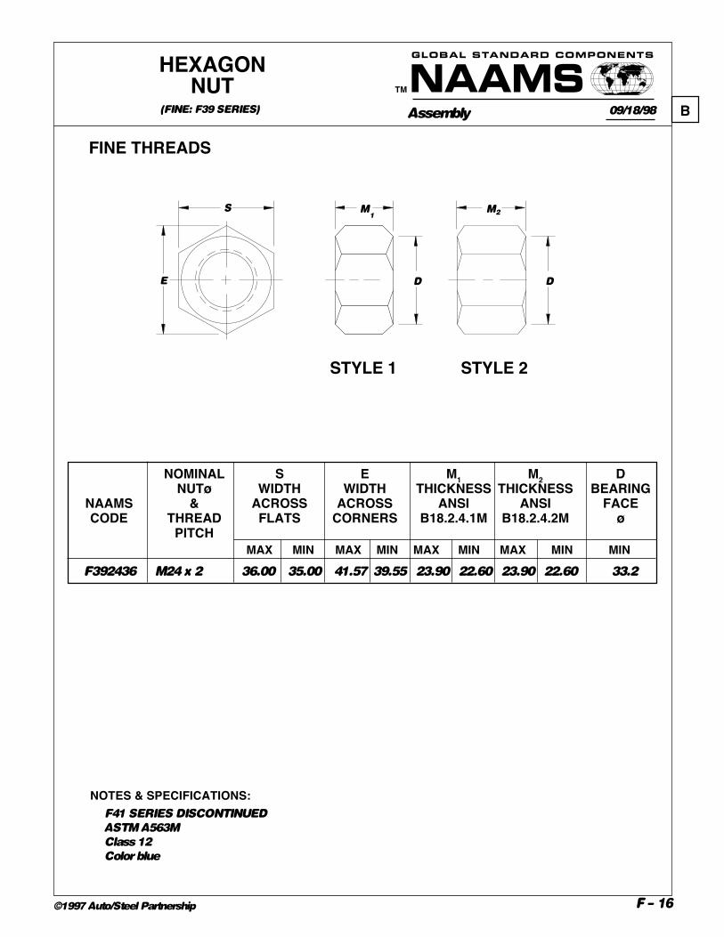
F392436 M24 x 2 36.00 35.00 41.57 39.55 23.90 22.60 23.90 22.60 33.2
NOMINAL S E M1 M2 DNUTø WIDTH WIDTH THICKNESS THICKNESS BEARING
NAAMS & ACROSS ACROSS ANSI ANSI FACECODE THREAD FLATS CORNERS B18.2.4.1M B18.2.4.2M ø
PITCH
FINE THREADS
NOTES & SPECIFICATIONS:F41 SERIES DISCONTINUED
ASTM A563M
Class 12
Color blue
HEXAGONNUT
(FINE: F39 SERIES) 09/18/98 B
E
S M
D
2M
D
1
STYLE 2STYLE 1
MAX MIN MAX MIN MAX MIN MAX MIN MIN
Assembly
TM
GLOBAL STANDARD COMPONENTS
F – 17©1997 Auto/Steel Partnership
E
S M
DW
C
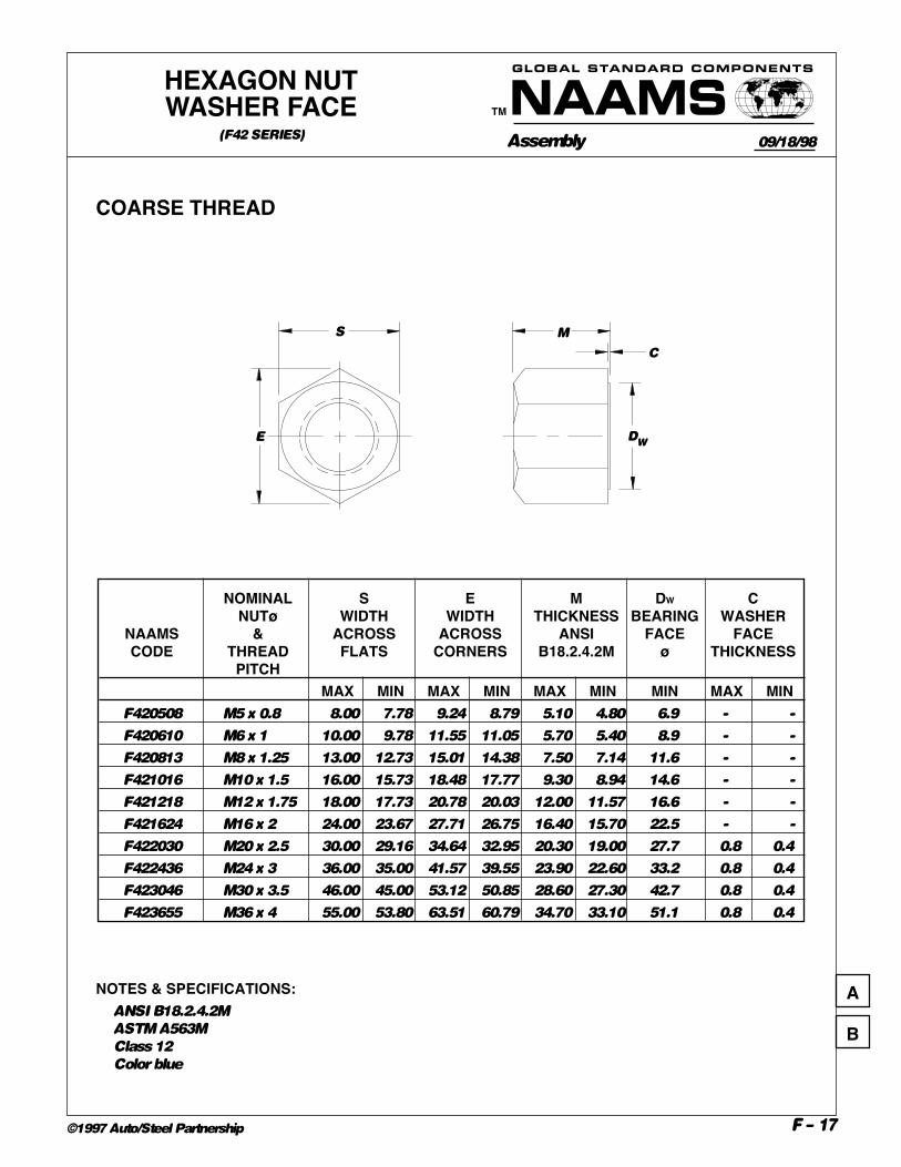
COARSE THREAD
NOMINAL S E M DW CNUTø WIDTH WIDTH THICKNESS BEARING WASHER
NAAMS & ACROSS ACROSS ANSI FACE FACECODE THREAD FLATS CORNERS B18.2.4.2M ø THICKNESS
PITCHMAX MIN MAX MIN MAX MIN MIN MAX MIN
F420508 M5 x 0.8 8.00 7.78 9.24 8.79 5.10 4.80 6.9 - -
F420610 M6 x 1 10.00 9.78 11.55 11.05 5.70 5.40 8.9 - -
F420813 M8 x 1.25 13.00 12.73 15.01 14.38 7.50 7.14 11.6 - -
F421016 M10 x 1.5 16.00 15.73 18.48 17.77 9.30 8.94 14.6 - -
F421218 M12 x 1.75 18.00 17.73 20.78 20.03 12.00 11.57 16.6 - -
F421624 M16 x 2 24.00 23.67 27.71 26.75 16.40 15.70 22.5 - -
F422030 M20 x 2.5 30.00 29.16 34.64 32.95 20.30 19.00 27.7 0.8 0.4
F422436 M24 x 3 36.00 35.00 41.57 39.55 23.90 22.60 33.2 0.8 0.4
F423046 M30 x 3.5 46.00 45.00 53.12 50.85 28.60 27.30 42.7 0.8 0.4
F423655 M36 x 4 55.00 53.80 63.51 60.79 34.70 33.10 51.1 0.8 0.4
NOTES & SPECIFICATIONS:ANSI B18.2.4.2M
ASTM A563M
Class 12
Color blue
HEXAGON NUTWASHER FACE
(F42 SERIES)09/18/98
A
B

Assembly
TM
GLOBAL STANDARD COMPONENTS
F – 18©1997 Auto/Steel Partnership
COARSE & FINE THREADS
NOMINAL S E M DNUT ø WIDTH WIDTH BEARING
NAAMS & ACROSS ACROSS THICKNESS FACECODE THREAD FLATS CORNERS ø
PITCHMAX MIN MAX MIN MAX MIN MIN
F451017 M10 x 1.25 17 - - - 5 - -
F451219 M12 x 1.25 19 - - - 6 - -
F451624 M16 x 1.5 24 - - - 8 - -
F452030 M20 x 1.5 30 - - - 10 - -
F452436 M24 x 2 36 - - - 13.5 - -
F452741 M27 x 2 41 - - - 13.5 - -
F453650 M36 x 2 50 - - - 16 - -
F470508 M5 x 0.8 8.00 7.78 9.24 8.79 2.70 2.45 6.9
F470610 M6 x 1 10.00 9.78 11.55 11.05 3.20 2.90 8.9
F470813 M8 x 1.25 13.00 12.73 15.01 14.38 4.00 3.70 11.6
F471016 M10 x 1.5 16.00 15.73 18.48 17.77 5.00 4.70 14.6
F471218 M12 x 1.75 18.00 17.73 20.78 20.03 6.00 5.70 16.6
F471624 M16 x 2 24.00 23.67 27.71 26.75 8.00 7.42 22.5
F472030 M20 x 2.5 30.00 29.16 34.64 32.95 10.00 9.10 27.7
F472436 M24 x 3 36.00 35.00 41.57 39.55 12.00 10.90 33.2
F473046 M30 x 3.5 46.00 45.00 53.12 50.85 15.00 13.90 42.7
F473655 M36 x 4 55.00 53.80 63.51 60.79 18.00 16.90 51.1
HEXAGONJAM NUT
(FINE: F45 SERIES, COARSE: F47 SERIES)
D
MS
E
11/12/97
NOTES & SPECIFICATIONS:ANSI B18.2.4.5M
ASTM A563M
CLASS 04
Color blue
C
B
A
D

Assembly
TM
GLOBAL STANDARD COMPONENTS
F – 19©1997 Auto/Steel Partnership
COARSE & FINE THREADS
NOMINAL S E M D CNUT ø WIDTH WIDTH BEARING WASHER
NAAMS & ACROSS ACROSS THICKNESS FACE FACECODE THREAD FLATS CORNERS ø THICKNESS
PITCHMAX MIN MAX MIN MAX MIN MIN MAX MIN
F480508 M5 x 0.8 8.00 7.78 9.24 8.79 2.70 2.45 6.9 - -
F480610 M6 x 1 10.00 9.78 11.55 11.05 3.20 2.90 8.9 - -
F480813 M8 x 1.25 13.00 12.73 15.01 14.38 4.00 3.70 11.6 - -
F461017 *M10 x 1.25 17 - - - 5 - - - -
F481016 M10 x 1.5 16.00 15.73 18.48 17.77 5.00 4.70 14.6 - -
F461219 *M12 x 1.25 19 - - - 6 - - - -
F481218 M12 x 1.75 18.00 17.73 20.78 20.03 6.00 5.70 16.6 - -
F461624 *M16 x 1.5 24 - - - 8 - - - -
F481624 M16 x 2 24.00 23.67 27.71 26.75 8.00 7.42 22.5 - -
F462030 *M20 x 1.5 30 - - - 10 - - - -
F482030 M20 x 2.5 30.00 29.16 34.64 32.95 10.00 9.10 27.7 0.8 0.4
F482436 M24 x 3 36.00 35.00 41.57 39.55 12.00 10.90 33.2 0.8 0.4
F462741 *M27 x 2 41 - - - 13.5 - - - -
F483046 M30 x 3.5 46.00 45.00 53.12 50.85 15.00 13.90 42.7 0.8 0.4
F463650 *M36 x 2 50 - - - 16 - - - -
F483655 M36 x 4 55.00 53.80 63.51 60.79 18.00 16.90 51.1 0.8 0.4
NOTES & SPECIFICATIONS:ANSI B18.2.4.5M
ASTM A563M
Class 04
Color blue
HEXAGON JAM NUTWITH WASHER FACE(FINE: F46 SERIES COARSE: F48 SERIES)
D
MS
E
C
05/14/97
* Fine thread series (F46 Series)
A
B

Assembly
TM
GLOBAL STANDARD COMPONENTS
F – 20©1997 Auto/Steel Partnership
BA
C
NOTES & SPECIFICATIONS:M6-M10 – Rc 38-45 through hardened (except as noted)
M12 & larger – ASTM F436M
Color blue
HARDENEDWASHER
(F62 SERIES)
(ASTM F436M)
09/10/97
A
B
C
NAAMS NOMINAL A B CCODE WASHER INSIDE ø OUTSIDE ø THICKNESS
MAX MIN MAX MIN MAX MINF620614 6 7.3 7.0 13.6 12.6 4.0 2.7
F620818 8 9.8 9.0 18.4 17.1 4.0 2.7
F621022 10 11.8 11.0 22.0 20.7 4.0 2.7
F621025* 10 10.8 10.2 25.3 24.7 5.0 4.0
F621227 12 14.4 14.0 27.0 25.7 4.6 3.1
F621634 16 18.4 18.0 34.0 32.4 4.6 3.1
F622042 20 22.5 22.0 42.0 40.4 4.6 3.1
F622244 22 24.5 24.0 44.0 42.4 4.6 3.4
F622450 24 26.5 26.0 50.0 48.4 4.6 3.4
F622756 27 30.5 30.0 56.0 54.1 4.6 3.4
F623060 30 33.6 33.0 60.0 58.1 4.6 3.4
F623672 36 39.6 39.0 72.0 70.1 4.6 3.4
*Special purpose for locating pin retainer assemblies
1020 H.R.S. carb & harden 1.0 deep 38-45 Rc

Assembly
TM
GLOBAL STANDARD COMPONENTS
F – 21©1997 Auto/Steel Partnership
D2
L
D3 D1
B
T
A
C
COLOR THIS END BLUE
m6
D1 Dia. 6 8 10 12 16 20 25C 2.1 2.6 3 3.8 4.6 6 6
D2 MAX. M4 X 0.7 M5 x 0.8 M6 x 1 M6 x 1 M8 x 1.25 M10 x 1.5 M16 x 2
B 6 8 10 12 16 18 24
D3 4.3 5.3 6.4 6.4 8.4 10.5 17
A 1 1.2 1.2 1.2 1.5 1.5 2
T MIN. 10 12 16 20 25 28 35
16 X
20 X X
24 X X X
28 X X X X
32 X X X X X
40 X X X X X X
50 X X X X X X X
60 X X X X X X X
70 X X X X X X
80 X X X X X X
90 X X X X X
100 X X X X X
120 X X X X
NOTES & SPECIFICATIONS:Material, case hardened alloy steel – shear strength: 825 MPa (120ksi)
ANSI B18.8.5M
Precision ground
Provide for air release (e.g., machine a flat, spiral, etc.)
Color non-tapped end blue
L
PULL DOWELPIN
(F91 SERIES)
CODING ON FOLLOWING PAGE
09/18/98
A
B

Assembly
TM
GLOBAL STANDARD COMPONENTS
F – 22©1997 Auto/Steel Partnership
NAAMS NOM. SIZE,CODE AND
LENGTHF910616 6x16
F910620 6x20
F910624 6x24
F910628 6x28
F910632 6x32
F910640 6x40
F910650 6x50
F910660 6x60
F910820 8x20
F910824 8x24
F910828 8x28
F910832 8x32
F910840 8x40
F910850 8x50
F910860 8x60
F910870 8x70
F910880 8x80
F911024 10x24
F911028 10x28
F911032 10x32
F911040 10x40
F911050 10x50
F911060 10x60
F911070 10x70
F911080 10x80
F911090 10x90
F911010 10x100
F911228 12x28
F911232 12x32
F911240 12x40
F911250 12x50
NAAMS NOM. SIZE,CODE AND
LENGTHF911260 12x60
F911270 12x70
F911280 12x80
F911290 12x90
F911210 12x100
F911212 12x120
F911632 16x32
F911640 16x40
F911650 16x50
F911660 16x60
F911670 16x70
F911680 16x80
F911690 16x90
F911610 16x100
F911612 16x120
F912040 20x40
F912050 20x50
F912060 20x60
F912070 20x70
F912080 20x80
F912090 20x90
F912010 20x100
F912012 20x120
F912550 25x50
F912560 25x60
F912570 25x70
F912580 25x80
F912590 25x90
F912510 25x100
F912512 25x120
PULL DOWELPIN CODING
(F91 SERIES)04/09/97
A

Assembly
TM
GLOBAL STANDARD COMPONENTS
F – 23©1997 Auto/Steel Partnership
PREFERRED METRICFASTENER SIZES
03/01/99
CHARTS / TEXT MOVED TO PAGE F - 2.3 C