fast track for autodesk® autocad® mep power users
TRANSCRIPT

Fast Track for Autodesk® AutoCAD® MEP Power
Users David Butts – Gannett Fleming
MP1523-L
Being an Autodesk® AutoCAD® Architecture or Autodesk® AutoCAD® MEP user is like being a younger sibling of an over-achieving brother or sister. However, we've got some tricks up our sleeves and AutoCAD has some tools and features that the Autodesk® Revit® hands-on lab, we cover tips for creating and maximizing projects using AutoCAD Architecture, Revit, or plain AutoCAD for MEP design; key features for AutoCAD MEP users that aren’t available in Revit MEP; using MEP models for energy analysis and other external applications; and creating custom content quickly for 3D projects. Join us for this informationworld, featuring the longest-tenured MEP modeling product in the Autodon some of my tools to help you get started.
Learning Objectives At the end of this class, you will be able to:
• List key components and features to use in a Project Navigator
• Describe key platform-specific featu
• Make full use of MEP models for external analysis applications, such as Autodesk® Green Building Studio®, Project Vasari, and more
• Apply tips for creating and managing custom AutoCAD MEP block
About the Speaker
David is a BIM Specialist for Gannett Fleming, a multi
PA, with 60 offices in the US and overseas. Based in the Raleigh, NC office, he provides BIM
Implementation and training for the firm's engineering design software, including Revit, Navisworks,
AutoCAD MEP/P&ID and more. He has 28 years of experience in both the design and Autodesk VAR
channel, spending 13 years working as an instructor and consultant for the Autodesk building d
product line. David also worked as a training manager while in the channel, and was a member of the
Autodesk ATC Advisory Board for 2009
earned the MEP Implementation Certified Expert ti
was named the Top Speaker for both labs and lectures at AU 2011. As an author, he also contributes to
4D Technology's CADLearning training programs and has written several training manuals for Revit
MEP.
Email: [email protected]
Fast Track for Autodesk® AutoCAD® MEP Power
Being an Autodesk® AutoCAD® Architecture or Autodesk® AutoCAD® MEP user is like being a achieving brother or sister. However, we've got some tricks up our sleeves
and AutoCAD has some tools and features that the Autodesk® Revit® world doesn't have yet. In this on lab, we cover tips for creating and maximizing projects using AutoCAD Architecture, Revit, or
plain AutoCAD for MEP design; key features for AutoCAD MEP users that aren’t available in Revit MEP; energy analysis and other external applications; and creating custom content
quickly for 3D projects. Join us for this information-filled class that helps you be competitive in the BIM tenured MEP modeling product in the Autodesk lineup. And get your hands
on some of my tools to help you get started.
At the end of this class, you will be able to:
List key components and features to use in a Project Navigator-based project
specific features and workflows available in AutoCAD MEP
Make full use of MEP models for external analysis applications, such as Autodesk® Green Building Studio®, Project Vasari, and more
Apply tips for creating and managing custom AutoCAD MEP block-based and parametric
David is a BIM Specialist for Gannett Fleming, a multi-discipline engineering firm based in Camp Hill,
PA, with 60 offices in the US and overseas. Based in the Raleigh, NC office, he provides BIM
the firm's engineering design software, including Revit, Navisworks,
AutoCAD MEP/P&ID and more. He has 28 years of experience in both the design and Autodesk VAR
channel, spending 13 years working as an instructor and consultant for the Autodesk building d
product line. David also worked as a training manager while in the channel, and was a member of the
Autodesk ATC Advisory Board for 2009-10. He is a Revit Architecture Certified Professional, and also
earned the MEP Implementation Certified Expert title. David has spoken at AU for several years, and
was named the Top Speaker for both labs and lectures at AU 2011. As an author, he also contributes to
4D Technology's CADLearning training programs and has written several training manuals for Revit
Fast Track for Autodesk® AutoCAD® MEP Power
Being an Autodesk® AutoCAD® Architecture or Autodesk® AutoCAD® MEP user is like being a achieving brother or sister. However, we've got some tricks up our sleeves
world doesn't have yet. In this on lab, we cover tips for creating and maximizing projects using AutoCAD Architecture, Revit, or
plain AutoCAD for MEP design; key features for AutoCAD MEP users that aren’t available in Revit MEP; energy analysis and other external applications; and creating custom content
filled class that helps you be competitive in the BIM esk lineup. And get your hands
Make full use of MEP models for external analysis applications, such as Autodesk® Green Building
based and parametric content
discipline engineering firm based in Camp Hill,
PA, with 60 offices in the US and overseas. Based in the Raleigh, NC office, he provides BIM
the firm's engineering design software, including Revit, Navisworks,
AutoCAD MEP/P&ID and more. He has 28 years of experience in both the design and Autodesk VAR
channel, spending 13 years working as an instructor and consultant for the Autodesk building design
product line. David also worked as a training manager while in the channel, and was a member of the
10. He is a Revit Architecture Certified Professional, and also
tle. David has spoken at AU for several years, and
was named the Top Speaker for both labs and lectures at AU 2011. As an author, he also contributes to
4D Technology's CADLearning training programs and has written several training manuals for Revit

Fast Track for Autodesk® AutoCAD® MEP Power Users
2
Introduction
I’m a lucky guy...my career runs parallel to the guy who’s dad owns the toy store. I get to try out
and break everything, to see how well it will sell – and how it will make us money. For me, that
means spending a lot of time with a variety of design applications, including AutoCAD MEP and
Revit MEP, among several others. Every project that I’ve worked on for the past three decades
has minor variations in how it’s defined, and how the tools are used.
For engineering firms that use AutoCAD MEP that could be a wide open statement, since the
beauty – and weakness – of AutoCAD is the variety of approaches that can be used. But when
you’re working in a modeling environment versus a drafting exercise, you need to adjust your
workflow and design processes accordingly. In this lab, we’re going to take a look at some of
the more obscure items that can either cause you fits, or really make your life easier when using
this tool. Let’s get rolling…
Getting the Most from Project Navigator in AutoCAD MEP
In our first exercise, we’re going to take a look at getting the most from Project Navigator in the
MEP environment. The example is based on a combined sewer overflow project we designed in
the last year. While this sample is not identical to the original, it should give you an idea of how
this approach will work, if you’re using AutoCAD MEP. One important note – the steps in this
process are similar to how I would setup a multiple structure/building site in Revit.
Bases – UCS’s – Rotated Views – and Levels!
When you are working on a typical building design, there are a couple of different approaches
you can take. The first, and more traditional method, is to create a drawing base file for each
building, with a specific corner of the building at a 0,0 insertion point. This base typically
represents a 3’-4’ cut plane above a specific floor level. When you’re working in a disconnected
environment, where items aren’t connected across a site, this works well. But the majority of
projects we’ve worked on the past few years have included multiple buildings or structures, so
we changed our work process.
For example, a water treatment plant usually contains several smaller structures that are
interconnected by piping, conduit, etc. The invert elevations and connection points between the
buildings are critical, so making sure everything lines up takes precedence. And by the way –
not everything you use in Project Navigator has to be a Project-specific tool. There’s a lot of cool
AutoCAD tricks you can leverage in the project environment.
So how would I define this project?

Fast Track for Autodesk® AutoCAD® MEP Power Users
3
When you’re working on a site-specific project, nothing is ever at true ortho angles, so you have
to know how to put all of this together. Let’s start by looking at our sample project. Instead of
using separate files for each building, where I’ve created the two buildings in the same file.
Exercise 1: Reviewing the Base Plan Setup
To begin this exercise:
1. Make sure the Gannett Fleming WTP Example is the current project.
2. From the Constructs tab, Process category, open the Process Model construct.
3. There are two buildings in this construct. Note that they are NOT co-planar (a $10 word
that means they don’t line up).
This view is designed as an overall representation of buildings that start from the same finish
floor elevation. Drawing orthographic linework is still constrained by the UCS axis and the view
rotation, so let’s fix the chemical building orientation to draw piping at right angles to the
building.
4. From the command line, enter DV for DVIEW. When prompted, select the linked
architectural drawing.
5. Enter TW to twist the view. Enter -5 for the rotation angle (I’ve cheated, and already
determined the angle difference from the XY plane). Press ESC to clear the command,
after the view is rotated.

Fast Track for Autodesk® AutoCAD® MEP Power Users
4
6. The chemical treatment building is now flat, but the XY axis is still set to the original
world coordinates.
7. From the command line, type UCS and press enter.
8. When prompted, type V and press enter. The UCS axis is now oriented to this view, to
allow the correct placement of pipe relative to the building.

Fast Track for Autodesk® AutoCAD® MEP Power Users
5
9. From the Home tab, select the Pipe command from the Build panel.
10. On Properties, set the routing preference to DI Class 250, the size to 12” and the
elevation to 4’. (Note: the elevation is relative to the XY axis elevation in this drawing).
Draw a segment down away from the building 10’:
11. From properties, change the elevation to -4’. Draw another pipe segment to the left
about 70’, and press ENTER when complete.
Fast Track for Autodesk® AutoCAD® MEP Power Users
6
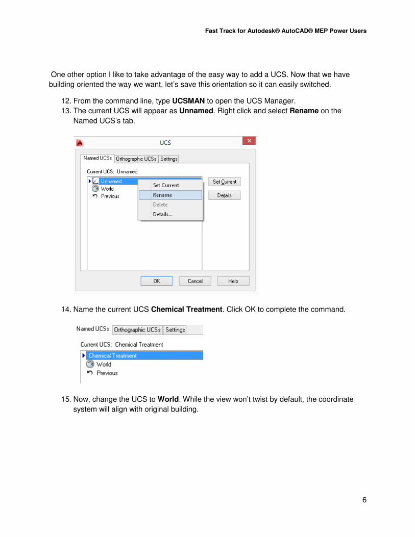
One other option I like to take advantage of the easy way to add a UCS. Now that we have
building oriented the way we want, let’s save this orientation so it can easily switched.
12. From the command line, type UCSMAN to open the UCS Manager.
13. The current UCS will appear as Unnamed. Right click and select Rename on the
Named UCS’s tab.
14. Name the current UCS Chemical Treatment. Click OK to complete the command.
15. Now, change the UCS to World. While the view won’t twist by default, the coordinate
system will align with original building.

Fast Track for Autodesk® AutoCAD® MEP Power Users
7
To make the view rotate when changing UCS’s, open the UCS Manager tool again.
16. Click Settings. Under UCS Settings, select Update View to Plan when UCS is
changed.
17. Click Ok. Alternate the two UCS settings, and note how the views rotate.

Fast Track for Autodesk® AutoCAD® MEP Power Users
8
Chemical Treatment WCS
Here’s another trick. Make sure the Chemical Treatment UCS is the current UCS.
18. On the View Cube, select the UCS drop down. Select New UCS.
19. When prompted to specify the origin, enter 0,0,-4’.
20. When prompted to specify a point on the X axis, make sure Ortho is enabled, and select
a point towards the right. Press Enter twice to complete the command.
21. A new Unnamed UCS appears. Return to the UCS manager, and rename it to
Underground Main Centerline. Click OK to complete the command.

Fast Track for Autodesk® AutoCAD® MEP Power Users
9
22. Let’s add another pipe. Select the last pipe segment drawn, and then click Add
Selected. This will map the same properties used to start the new pipe, but take a look
at the elevation. Instead of 4’ as originally selected, it’s now at 8’.
Why is this important? Simple – if you are routing pipe that needs to be based on a real world
elevation, but you are working with an existing project that was created at a “0” elevation, the
new UCS can be used to correct this. As long as you know the difference in elevation of the
current level, and the real world elevation, you can make this simply change without rebuilding
the model.
Let’s take another approach, and learn how to add levels at varying elevations in a project.
1. From the Project Navigator, select the Project Tab. Click Edit Levels.

Fast Track for Autodesk® AutoCAD® MEP Power Users
10
2. Note the different elevations that are already assigned, and available for use on any
drawing in the project. To add a lower level, start by deselecting the Auto-Adjust
Elevation tool.
3. Select the Grade level, and then right click. Select Add Level Below.
4. The new level will be added, with a number for the name. Change the name to Pump
Pit.
5. Select Auto-Adjust Elevation. A dialog about adjusting existing levels will occur. Select
Adjust existing levels.

Fast Track for Autodesk® AutoCAD® MEP Power Users
11
6. Change the Pump Pit elevation to 50’. Note how all elevations are now adjust upward.
This tool will help you move items in your project up to real world elevations. The advantage of
this method is that it also adjusts the elevation of all objects in a model file to reflect the new
elevation. To test this, click OK to exit the dialog. Select Yes when prompted to regenerate all
views in the project.
While building and corresponding models will be correctly located in a combined model, at the
correct elevation, the UCS settings remain unchanged. Why?
Because the UCS is relative to the current drawing, not to the project’s overall elevations.
Having the different UCS types included in your construct helps smooth model alignments for
piping and other MEP components. You can also repeat this step in a view drawing, and add
your tags, dimensions and text. This will help keep annotations aligned with the view orientation.
But when you want to work at real world elevations, make sure you define the correctly in
Project Navigator first. You’ll find that moving items vertically is really easy in AutoCAD MEP –
even easier than editing levels in Revit!

Fast Track for Autodesk® AutoCAD® MEP Power Users
12
Leveraging AutoCAD MEP to Assist Project Workflows I’ve been a big fan of the schematic drafting tools in AutoCAD MEP for years. I’ve used them on
almost every project I’ve worked on. When I started my current position, I found that we still
depend heavily on CAD customizations and symbology that was focused more on layer control
that improving work process.
This year, we began a sub-implementation of AutoCAD MEP for several reasons. One was
review projects that were still based in plain AutoCAD, and learn how to leverage MEP tools to
improve production on projects where the architecture and structure was still being completed in
2D. The more interesting project was learning how to leverage the schematic tools to get a
better understanding of object based programming, and use it for applications like Revit that
don’t offer these tools. We also were studying how to associate information with a schematic
representation of an electrical or plumbing schematic and associate it with-BIM object data in
Revit. In this exercise, we’ll take a look at these two approaches.
Exercise 2: Leveraging AutoCAD MEP Schematic Tools
To begin this exercise:
1. Make sure the Gannett Fleming WTP Example is the current project.
2. Set the Schematic workspace current.
3. From the View tab in Project Navigator, open the Power Riser Diagram. Review the
basic symbols that have been placed in the drawing.
Schematic symbols and linework have a “symbiotic” relationship with each other. I also refer to
this as the “sibling” relationship. In other words, you can’t do something to one without it having
an effect on another.

Fast Track for Autodesk® AutoCAD® MEP Power Users
13
1. Select the first panel. Click on a grip, and then drag the panel to the left. Note how the
schematic line moves with the panel.
2. Repeat this step with a motor, dragging it down to add a little room on the schematic
line.
3. From the ribbon, Home tab, Build panel, click Schematic Symbol.

Fast Track for Autodesk® AutoCAD® MEP Power Users
14
4. On the properties palette, select the Symbol tool. Locate the Circuit Breaker, and then
click OK.
5. Locate the breaker along the schematic line.
6. Let’s create a few property set definitions that can be used to replace text that normally
would be used to label the circuit. From the Manage tab, click Style Manager.
7. Under Documentation objects in the current drawing, click Property Set Definitions.
8. Click Electrical Schematic Object as the current property set.

Fast Track for Autodesk® AutoCAD® MEP Power Users
15
9. On the Applies tab, note how this is applied to schematic symbols that include the
Electrical Device classification.
10. Click the Definitions tab. Click Add Manual to create a new definition, and name it
Circuit Number, with no spaces in the name. Click OK to add the definition.
11. Click OK to exit the dialog.
12. Select the circuit breaker. On the Properties palette, select the Extended Data tab.
13. For Classification, change this to use the Electrical Device.

Fast Track for Autodesk® AutoCAD® MEP Power Users
16
14. Select the Circuit breaker again. This time, use the Add Property Sets tool on the
Extended Data tab.
15. Make sure the Electrical Schematic Object is selected, and then select OK. The
definition is now available for editing.

Fast Track for Autodesk® AutoCAD® MEP Power Users
17
In this case, we added all of the property sets under one classification, but you can create as
many of these as needed, to correctly sort data associated with objects. The definition can also
be added to a tag, which will leverage the data assigned to this definition to populate it.
So why go to the trouble to do this, and what does it have to do with Revit?
First, we’re using the diagram for more than just a drafting tool. We’re using it to associate data
with symbols that can be associated with other panels, electrical devices, views and other
drawings. The data can be extracted to Excel, where it can be sync’d via links to other
spreadsheets, or databases.
16. From the command line, type ScheduleAdd. In the properties dialog, set the style to
Electrical Panels, and make sure Update Automatically and Add New Objects
Automatically are set to Yes.
17. In the drawing use a window selection to pick the panels. This schedule is defined to
only use objects that have the Electrical Panels classification assigned to the parts, so
don’t worry if you pick other devices by accident.

Fast Track for Autodesk® AutoCAD® MEP Power Users
18
18. Press ENTER after picking the parts, and then place the schedule. The schedule will
contain any information you can associate with the panel.
19. To export the table, simply select it, right click and choose Export. You can save to an
Excel XLS, CSV or TXT file as needed. As you update the table, simply export it again,
and overwrite the data.
Fast Track for Autodesk® AutoCAD® MEP Power Users
19
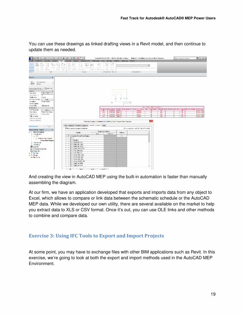
You can use these drawings as linked drafting views in a Revit model, and then continue to
update them as needed.
And creating the view in AutoCAD MEP using the built-in automation is faster than manually
assembling the diagram.
At our firm, we have an application developed that exports and imports data from any object to
Excel, which allows to compare or link data between the schematic schedule or the AutoCAD
MEP data. While we developed our own utility, there are several available on the market to help
you extract data to XLS or CSV format. Once it’s out, you can use OLE links and other methods
to combine and compare data.
Exercise 3: Using IFC Tools to Export and Import Projects
At some point, you may have to exchange files with other BIM applications such as Revit. In this
exercise, we’re going to look at both the export and import methods used in the AutoCAD MEP
Environment.

Fast Track for Autodesk® AutoCAD® MEP Power Users
20
IFC stands for Industry Foundation Class, and it’s a file format that is universally shared
between CAD platforms. The intent is that an object in a program like AutoCAD MEP can be
converted into the same type of object in Revit, or other BIM applications.
Exporting from AutoCAD MEP to Revit
1. Make sure you have the AU 2013 MEP Base Complete.dwg open.
2. In order for an object to be exported to IFC, it has to have an object classification
assigned. To look at the default styles go to ProgramData\Autodesk\MEP
2014\enu\Styles directory and open the IfcPropertySet_Definitions (MEP).dwg file.
3. In the style manager, look at the classification definitions under Multi-purpose objects.
IFC properties can be assigned to these objects:
4. Once the items are selected, the classifications tab lists the information associated with
an MEP object that will be exported:

Fast Track for Autodesk® AutoCAD® MEP Power Users
21
5. To use these in a file, and assign them to MEP objects, you have to copy them into your
current drawing. Use copy and paste in the style manager to add both classification
definitions to the current drawing:

Fast Track for Autodesk® AutoCAD® MEP Power Users
22
6. Select OK to exit the style manager. Now that they’re in the drawing, you can edit the
properties of objects to assign the classification. I’ll grab the ductwork, and then go to the
properties palette:

Fast Track for Autodesk® AutoCAD® MEP Power Users
23
7. Select the Classification, and then expand HVAC objects until you locate duct
segments. This tells Revit and other BIM applications what type of object this 3D solid
represents. For most other parts, IFC Type Classifications are mapped to MvPart
Objects (such as equipment, panels, and devices) automatically. This classification is
added in the Autodesk Catalog Editor by default. You can modify this classification or
add more classifications to the content library in the Autodesk Catalog Editor.
8. Once you’ve added the correct classifications to MEP objects, click OK to exit the dialog.
9. Next, we’ll review the IFC export settings. From the application menu, select the Export
tool, and then select IFC. The options are located on the export dialog:
10. If you don’t want to include the architectural base, you can deselect that option. Next,
select Options. The Objects tab lists all objects that loaded into a drawing – you can
choose to add or remove objects as needed:

Fast Track for Autodesk® AutoCAD® MEP Power Users
24
11. The view tab shows the name of the view that will be created, when imported in other
applications such as Revit:
12. After you review the options, click OK. Now, you can run the export. The IFC file is
created in the project folder. To test this, I’m going to open the file in Revit. Before doing
this, open the IFC Import options on the Application menu, under Open:

Fast Track for Autodesk® AutoCAD® MEP Power Users
25
13. Before importing an IFC file, you need to go through and map IFC class names to
Categories and sub-categories. This tells the MEP object what is used to control its
display in Revit. You can also select the default Revit RTE file to use as a starting point,
so make sure you select this before opening the file.
TIP: I’ve saved a copy of the text file mappings for this class, which should be available
online under the course materials.
Once the IFC file is imported, the duct will appear something like this:

Fast Track for Autodesk® AutoCAD® MEP Power Users
26
The imported objects take on most of the characteristics of the equivalent objects in Revit. You
may need to check IFC mappings in both the AutoCAD MEP file and the Revit file during this
process, but this represents the level of detail that can be obtained when moving from
AutoCAD MEP to Revit.
Be aware that imported objects may not completely take on the behavior of a normal duct. For
example, the duct is treat like a duct with properties assigned, but it does not include the
connection, system or sizing behavior. You have to add a connector to attach duct to it.
Exporting from Revit to AutoCAD MEP
Next, let’s review how to import an IFC file into AutoCAD MEP, and create a project. To save
some type, I’ve already created the IFC file to use in this exercise, so we don’t need to work in
Revit at this time.
1. Make sure that you close any open drawings, and then create a new drawing using one
of the AECB model templates (you need at least one drawing open to open an IFC file).
From the Application Menu, click Open. Select the IFC file type.

Fast Track for Autodesk® AutoCAD® MEP Power Users
27
2. In the Import dialog, select the browse button to locate the CENTRAL_All.IFC file
3. Select the option to create a project.
4. Use the Browse button to locate the project in the class folder (MP1523-L).
5. Make sure the AECB Model (US Imperial CTB).dwt file is the current template file.

Fast Track for Autodesk® AutoCAD® MEP Power Users
28
6. Click Options. Make sure that all object element types are selected, and use the Create
New Style with unique name option is selected. Click OK.
7. Click Create to complete the command
It may take a few minutes to process the entire project. You may also get a warning about
mismatched units. This occurs when the Revit units, measure as Feet, and not the same as the
selected template, where the default units are in inches.
8. Select Use Selected Drawing Template when prompted.
9.

Fast Track for Autodesk® AutoCAD® MEP Power Users
29
While this is processing, let’s go ahead and review what the outcome will be. AutoCAD MEP will
create constructs at every level that is defined in the project. You may wind up with more
constructs that you would typically create in an AutoCAD MEP project.
10. When finished, the program will create a project in same location as the IFC file. The
Project Name in Revit will be used as the name for the AutoCAD MEP Project. The
project will be set current, so open the Project Navigator.
11. Open the view drawing, Long Term Control Plan Phase II Set the view to a southwest
isometric view.
You can now select different components by selecting one of the reference files, and
opening the file to review how the objects are defined.
In regards to using IFC imports in AutoCAD MEP, there are pros and cons. For basic
Architectural imports, you can get a pretty good model representation, with most objects easily
recognized as walls, doors and windows. Other objects are converted as multi-view blocks.
The image below is from a full MEP export of the same project. Due to the amount of time it can
take to create the file, I’m just adding an image, so you can get a look at how an exported Revit
MEP model would appear.

Fast Track for Autodesk® AutoCAD® MEP Power Users
30
The export to AutoCAD MEP from Revit is even more limited for MEP objects, with multi-views
blocks used to define equipment, duct, pipes, fittings and more. The best functional use is for
coordination purposes with other designers that are using Revit or other MEP engineering
applications that can export MEP models.
In summary, there are a couple of critical items in regards to workflow that you need to keep in
mind when IFC use becomes an issue:
- Exporting from AutoCAD MEP to Revit gives you correctly identifiable pipes, duct,
equipment and more based on classifications, but no system integration
- Exporting from Revit to AutoCAD MEP gives you limited AutoCAD Architecture
capabilities, but only block-based components for MEP objects.
- Best use is for coordination between components when different firms are engaged in a
project, and using different software packages.
Leveraging AutoCAD MEP Models in External Analysis Applications One of the features I’ve liked about AutoCAD MEP for a long time has been its ability to work
with external applications, including Green Building Studio, IES Virtual Environment, Vasari and
others. One of the reasons why this works so well is due to the behavior of architectural objects
such as walls, doors and windows, and space and zone objects for engineering. In this lesson,
we’ll learn how to make sure our model is optimized for these applications, and then load them
up on BIM 360 to use with the Autodesk online solutions.
Exercise 4 – Reviewing and Uploading an AutoCAD MEP Model for Analysis
Fast Track for Autodesk® AutoCAD® MEP Power Users
31
In this exercise, we’re going to start with the process model, and add spaces and zones. Once
these are defined, we’ll review the settings for both objects.
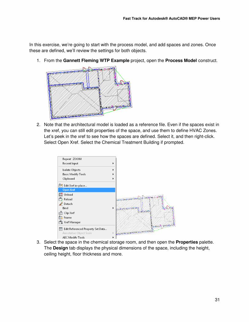
1. From the Gannett Fleming WTP Example project, open the Process Model construct.
2. Note that the architectural model is loaded as a reference file. Even if the spaces exist in
the xref, you can still edit properties of the space, and use them to define HVAC Zones.
Let’s peek in the xref to see how the spaces are defined. Select it, and then right-click.
Select Open Xref. Select the Chemical Treatment Building if prompted.
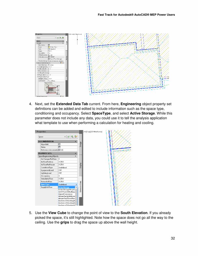
3. Select the space in the chemical storage room, and then open the Properties palette.
The Design tab displays the physical dimensions of the space, including the height,
ceiling height, floor thickness and more.
Fast Track for Autodesk® AutoCAD® MEP Power Users
32
4. Next, set the Extended Data Tab current. From here, Engineering object property set
definitions can be added and edited to include information such as the space type,
conditioning and occupancy. Select SpaceType, and select Active Storage. While this
parameter does not include any data, you could use it to tell the analysis application
what template to use when performing a calculation for heating and cooling.
5. Use the View Cube to change the point of view to the South Elevation. If you already
picked the space, it’s still highlighted. Note how the space does not go all the way to the
ceiling. Use the grips to drag the space up above the wall height.

Fast Track for Autodesk® AutoCAD® MEP Power Users
33
6. While in the view, and with the space selected, right-click. Select the Select Similar tool
to add the rest of the spaces. Set the Ceiling Height to 13’ 8” for all examples.
7. Save the drawing, and then close it. You’ll be returned to the Process Model, and update
the reference file.
8. Now let’s add some HVAC data. Make sure the HVAC workspace is the current
workspace.
9. From the Analyze tab, select the Zone tool. Place a zone object next to the building.
10. Once the zone is placed, pick it. Use the plus sign grip to select the spaces in the
architectural model – yes, you can pick spaces in referenced files – something Revit
can’t do.

Fast Track for Autodesk® AutoCAD® MEP Power Users
34
11. After selecting all of the spaces, press enter to complete the command.
12. While the zone is still selected, right click. Select the Space/Zone Manager tool. You
can also select this from the ribbon, Zone tab.

Fast Track for Autodesk® AutoCAD® MEP Power Users
35
13. When the dialog opens, select both options at the bottom of the dialog for Show All
Zones and Spaces, and Show Space Surfaces.
14. Expand the Zone. Under one of the spaces, select one of the wall surfaces. AutoCAD
MEP will recognize the style used to define the wall. The openings in the wall are also
indicated, along with their size. This occurs because the spaces are set to be associative
when placed. If you disable this feature, you can add or remove openings, or change the
style associated with the surface as needed.
Having the associative capability means that as the architect changes their model, the space is
automatically updated. Initially, it’s rare to get detailed architectural object information at the
start of a project. Having a generic object works, since it gives us the geometry to export to the
analysis application. Many of these applications include templates (including Trace and IES VE
Pro), that allow you to apply constructions based on assumptions. The model saves the time of
having to recreate the surfaces in the analysis application.
One important note – most external applications require zones to be defined, and associate
spaces place in occupied areas, prior to using the model for a gbXML import. But they don’t
require the architectural objects. You can place spaces without the arch model, and use them to
create an analytical model as needed. It’s just a bit more work later…
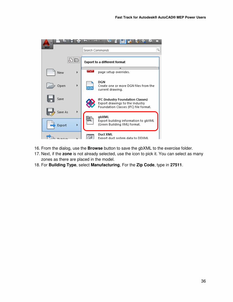
15. Save the file. From the Application menu, click Export. Select the gbXML option.
Fast Track for Autodesk® AutoCAD® MEP Power Users
36
16. From the dialog, use the Browse button to save the gbXML to the exercise folder.
17. Next, if the zone is not already selected, use the icon to pick it. You can select as many
zones as there are placed in the model.
18. For Building Type, select Manufacturing, For the Zip Code, type in 27511.

Fast Track for Autodesk® AutoCAD® MEP Power Users
37
19. Click Start. If the application returns an error, review the list. While you can still create
the gbXML file, you’ll need to make these adjustments once the model is opened in the
analysis tool. Click Close.
The file is now ready to use for analysis.
Since using Autodesk 360 in a lab may be a little time consuming, the next part will be
“demonstration only”, so sit back and relax…
Uploading Files to Autodesk 360
In order to use Autodesk 360 tools such as Green Building Studio for analysis, you have to
have an Autodesk product such as AutoCAD MEP covered by subscription. While anyone can
access Autodesk 360 to store and share files, analysis tools are only included with a
subscription.
Once you are logged in, select the Autodesk 360 tab on the ribbon. Click Open folder.

Fast Track for Autodesk® AutoCAD® MEP Power Users
38
When AutoCAD MEP is installed with the Autodesk 360 option, a holding folder is created on
your hard drive. If you copy files to this folder, they are automatically uploaded to the Autodesk
360 cloud.
So all I have to do is copy and paste my exported XML file to this location.
Next, I’ll return to AutoCAD MEP, and select the Launch Website – make sure you’re signed in
first. (Note: in some cases, you may have to restart AutoCAD MEP to launch the website after
copying files to the holding folder).

Fast Track for Autodesk® AutoCAD® MEP Power Users
39
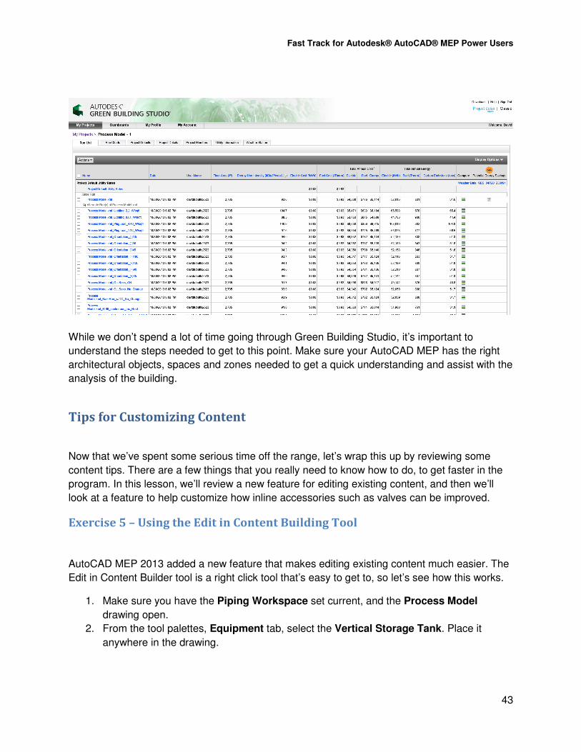
Once the website is open, the tools available with show up under Your 360 Benefits.
1. Click Autodesk Green Building Studio. From the webpage, select the Create New
Project tool.
2. Name the project as needed. Set the building type and schedule for occupancy. If you
are using a run for testing purposes, select the Test Project option. Otherwise, select
Actual Project. Select Continue.

Fast Track for Autodesk® AutoCAD® MEP Power Users
40
3. On the next screen, select the location for the project. You can enter an address, or just
select a point on the map.

Fast Track for Autodesk® AutoCAD® MEP Power Users
41
4. Once the address is entered, check and correct the time zone as needed. Set the
currency to US dollars, or select a different currency. Click Continue.
5. On the preferences page, you can control data access, contact preferences, and
approve the terms of use. Select the options you want and click Create Project to
finish.

Fast Track for Autodesk® AutoCAD® MEP Power Users
42
6. Once the project is defined, the Run List Page appears. You are prompted to set the
project defaults and utility information. Once these are reviewing, select the Actions pull
down. Click Upload gbXML file. Pick Browse.
7. If you want to use the file on the 360 account, a shortcut to your Autodesk 360 account
will appear. Click it. You can now select the gbXML and use it to produce a run.
Fast Track for Autodesk® AutoCAD® MEP Power Users
43
While we don’t spend a lot of time going through Green Building Studio, it’s important to
understand the steps needed to get to this point. Make sure your AutoCAD MEP has the right
architectural objects, spaces and zones needed to get a quick understanding and assist with the
analysis of the building.
Tips for Customizing Content
Now that we’ve spent some serious time off the range, let’s wrap this up by reviewing some
content tips. There are a few things that you really need to know how to do, to get faster in the
program. In this lesson, we’ll review a new feature for editing existing content, and then we’ll
look at a feature to help customize how inline accessories such as valves can be improved.
Exercise 5 – Using the Edit in Content Building Tool
AutoCAD MEP 2013 added a new feature that makes editing existing content much easier. The
Edit in Content Builder tool is a right click tool that’s easy to get to, so let’s see how this works.
1. Make sure you have the Piping Workspace set current, and the Process Model
drawing open.
2. From the tool palettes, Equipment tab, select the Vertical Storage Tank. Place it
anywhere in the drawing.

Fast Track for Autodesk® AutoCAD® MEP Power Users
44
3. Once the tank is placed, select it, and right click. Click Edit in Content Builder.

Fast Track for Autodesk® AutoCAD® MEP Power Users
45
4. This skips the steps of having to open the Manage tab, locate the Content Builder tool,
browse to find your part, and then choosing the Modify Part tool.
5. Select the Connectors tab. Expand the 120 Gallon tank, and pick Connector 6. Right
click and choose Edit Placement.

Fast Track for Autodesk® AutoCAD® MEP Power Users
46
6. The connection editor will appear. Connector 6 is highlighted in the model. The current
size is 2”. Under Connection Diameter, enter 1 1/2”.
7. Click OK to close the Connection editor.
8. Click OK to close the Modify Part dialog. When you return to the drawing, place another
tank. The connection is now set to 1 ½”.
Now that was easy.

Fast Track for Autodesk® AutoCAD® MEP Power Users
47
Exercise 6 – Converting a Manufacturer Part to an MVPart
In this exercise, we’ll take a 3D DWG that was converted from an SAT file using Fusion 360,
and turn it into an MVPart.
1. From the JWC Screenings Washer drawing, select the solid. Right Click, and choose
Convert > Multi-View Part.

Fast Track for Autodesk® AutoCAD® MEP Power Users
48
2. For the name, enter Screenings Washer. Set the type to Screen, and enter
Screenings Washer for the subtype. You can edit the subtype, but not the type. Set the
layer key to EQUIP. Select the Delete the Original Object option.
3. Click Next. On the Connectors page, right click on the part and choose Add Pipe
Connector.

Fast Track for Autodesk® AutoCAD® MEP Power Users
49
4. For the properties, name the connector Input. Click OK to continue.
5. Right click on the connector and choose Edit Placement.
6. Rotate the part to see the washdown connection. Note – some surfaces may get lost in
translation. Items created as weldments, or mesh surfaces, sometimes can’t be
converted….but fixing that is for another day in Inventor.

Fast Track for Autodesk® AutoCAD® MEP Power Users
50
7. Select the placement icon, and pick the center of the connector. Next, change the
normal so it reads 0,0,1 and points up. Set the size to 1.5”.
8. Press OK to close the connection editor.
9. Click Finish to close the dialog, and then take a look at the part. You now have an
MVPart that can be scheduled, and follow the display configuration rules. Nice!

Fast Track for Autodesk® AutoCAD® MEP Power Users
51
Exercise 7 - Adding and Editing Symbols and Annotation Planes to Valves
Working in 3D gives you the advantage of seeing your design from different viewpoints. IT also
helps to create section and elevation views automatically. AutoCAD MEP includes a feature
that makes the engineering models provide clearer detail levels for specific parts. This feature is
the ability to add front and left side working planes, and create custom 2D schematic symbols.
Let’s take a look at how this works.
1. Start a new drawing from the AECB Model template.
2. On the ribbon, Manage Tab, MEP Content Panel, select the Content Builder tool.
We’re going to edit an existing valve, and add the graphic symbol to the front view of the
model.
3. When the dialog opens, make sure the Part Domain is set to Multi-View Part. Under
the Mechanical Equipment section, browse to valves; expand the section, and then
select Gate Valves. One note: look for the symbol that has three arrows pointing to a
box. This indicates that the part is a block-based part.

Fast Track for Autodesk® AutoCAD® MEP Power Users
52
4. Select the Gate Valve-Butt-Welded-Class 150 part. Click the Modify Part Size icon to
continue.
5. The file will be opened, and the Content Builder dialog will appear. The default view is
for a plan view, so let’s take a look at how the current plan symbol is displayed. On the
dialog, expand the Modeling section, and then expand the Symbol and Annotation
Plane section.

Fast Track for Autodesk® AutoCAD® MEP Power Users
53
6. Expand the Top Symbol Plane. You’ll see two categories:
• Parametric Graphics allows you to create your own 2D symbol, and leverage
the existing model to define your part.
• Design Blocks allows you to import a 2D Symbol block and lets it be used to
represent the part in the plan, or in the front or left view planes.
7. To add our own symbol, the first important step is to turn on the workplane. Right-click
on Top Symbol Plane, and click Visible.
8. This will show the working plane. Use the view cube see where the plane is located in
the model:

Fast Track for Autodesk® AutoCAD® MEP Power Users
54
9. As an example, let’s check out the existing 2D geometry. Expand the Geometry section
and then right-click on the first Line 2D. Click Visible to turn this on.
10. To see the rest of the parts, repeat the steps for all of the lines and points. Note how the
icon becomes bold as the line or point is made visible:

Fast Track for Autodesk® AutoCAD® MEP Power Users
55
11. This displays the linework that is used when the view is set to the top plane, which is
where plan views are displayed. Our next step would be to turn on the Front Symbol
plane and use it to define a symbol for that point of view.
12. Right-click on the Symbol and Annotation Plane. Click Add Front Symbol Plane:
13. Once the plane is created, right-click on the new plane, and then click Visible to turn it
on.

Fast Track for Autodesk® AutoCAD® MEP Power Users
56
14. Once it’s visible, you can change to the front view.
15. Zoom into the view so you can see what you’re adding.
16. In order to link the geometry from the model to the symbol, you need to create
Coincident Points. These points link the symbol lines you create to the size of the
model. The quick way to create the reference points needed to link the new linework to
the model is to use the Projected Geometry tool. Right-click on Parametric Graphics,
and then click Add Geometry. Once the section expands, select the Project
Geometry… tool:

Fast Track for Autodesk® AutoCAD® MEP Power Users
57
17. You’ll be prompted to select a modifier – this is the body of the valve. Pick the shape; as
you move your mouse around the body, you’ll see a green preview line, which indicates
which edge is being used to create the line and points. Select the bottom of the body:
18. The line and points will be created.
19. Repeat this tool by right-clicking in the view, and selecting the Repeat
ADDCOLPROJGEOM tool.

Fast Track for Autodesk® AutoCAD® MEP Power Users
58
20. Select the two lines on either side of the top of the valve body, as shown here. Once
you’ve added all three lines, you’ll have the points you need; and they are automatically
constrained to the 3D model.

Fast Track for Autodesk® AutoCAD® MEP Power Users
59
21. Next, right-click on Parametric Graphics under the Front symbol Plane, and then click
Add Geometry. Select the Line… tool. Using the points as snap points, draw the four
lines as shown to create the symbol.
22. Make sure you have the Ortho tool turned off. The linework will be created similar to a
polyline. When finished, press ENTER to complete the command.

Fast Track for Autodesk® AutoCAD® MEP Power Users
60
23. You can delete any lines or points that aren’t needed to create the symbol, so delete the
highlighted below. Pick each segment or point and then use the DEL key to remove
them.
24. The remaining points that constrain the lines to the model can be turned off. By the way,
don’t delete these; the symbol will not work correctly if you remove them from the model.
To hide them, expand the Geometry section and then right-click on each point. Deselect
the Visible option, and the point will be turned off. Notice that these are fixed, which
means they are properly constrained to the model.

Fast Track for Autodesk® AutoCAD® MEP Power Users
61
25. The symbol is ready to use, but you aren’t finished yet. On the Content Builder dialog,
select the Validate tool.
26. If there are any errors in the model, they will show up here. Make sure the check mark is
green, and your model is correctly defined. Select the Options tool.
Make sure the following options are checked:
• Migrate-able Part Flag – so you can upgrade this to new releases;
• Custom Sizing Flag – so you can add custom sizes
27. AutoCAD MEP lets you assign the layer key from this dialog. Previously, you had to edit
this setting with the Catalog Editor. Make sure the Display symbol in Plan View is
deselected, so the new symbol does not appear from the top view.

Fast Track for Autodesk® AutoCAD® MEP Power Users
62
You’ve finished the task now and properly defined the symbol. Close the Content Builder
dialog, saving the changes when prompted. You can now load the valve into a drawing, and test
it to make sure it works. Use this tool to get the construction documents looking the way you
want!
Conclusion
Hopefully you’ve had a chance to look at some non-traditional procedures and tools that can
help refine your projects, and provide more detail. If you wind up working in a multiplatform
environment, the steps we’ve covered should make them run much smoother. For more help
down the road, keep up with my blog at mepd-cad.blogspot.com, or 4D Technologies
CADLearning series on AutoCAD MEP, which I’ve authored for the past few years.
Happy BIM’ing!

Fast Track for Autodesk® AutoCAD® MEP Power Users
63