fall arrestor connector subsystems (facss) · hinged closure for a falltech vll, a secondary safety...
TRANSCRIPT
User Instruction Manual
Single Anchor Fall Arrestor Connector Subsystems (FACSS)
This manual is intended to meet the Manufacturer's Instructions as required by ANSI Z359 and should be used as part of an employee training program as required by OSHA. This manual assumes the user has been trained in the use of this equipment.
WARNING
This product is part of a personal fall arrest, restraint, work positioning, suspension, or rescue system. A Personal Fall Arrest System (PFAS) is typically composed of an anchorage and a Full Body Harness (FBH), with a connecting device, i.e., a Shock Absorbing Lanyard (SAL), or a Self‐Retracting Device (SRD), attached to the dorsal D‐ring of the FBH. These instructions must be provided to the user of this equipment. The user must read and understand the manufacturer's instructions for each component or part of the complete system. Manufacturer's instructions must be followed for proper use, care, and maintenance of this product. These instructions must be retained and be kept available for the user’s reference at all times. Alterations or misuse of this product, or failure to follow instructions, may result in serious injury or death. A Fall Protection Plan must be on file and available for review by all users. It is the responsibility of the user and the purchaser of this equipment to assure that users of this equipment are properly trained in its use, maintenance, and storage. Training must be repeated at regular intervals. Training must not subject the trainee to fall hazards. When this equipment is in use the employer must have a rescue plan and the means at hand to implement it and communicate that plan to users, authorized persons, and rescuers. Consult a doctor if there is reason to doubt your fitness to safely absorb the shock of a fall event. Age and fitness seriously affect a worker’s ability to withstand falls. Pregnant women or minors must not use this equipment. NOTE: For further information, see ANSI Z359.
FallTech 1306 South Alameda Street Compton, CA 90221, USA
1‐800‐719‐4619 1‐323‐752‐0066
www.falltech.com ©2013
1
TABLE OF CONTENTS 1. DESCRIPTION 1.1 Vertical Lifelines (VLL) 1.2 Rope Grabs and Rope Grab Lanyard Sets (RGLS) 2. APPLICATION 2.1 Purpose 2.2 Personal Fall Arrest System 2.3 Fall Restraint 2.4 Rescue, Positioning, Riding, Climbing 2.5 Application Limits 3. SYSTEM REQUIREMENTS 3.1 Capacity 3.2 Compatibility of Connectors 3.3 Compatibility of Components 3.4 Making Connections 3.5 Personal Fall Arrest System
3.5.1 PFAS Anchorage Strength 3.6 Restraint System
3.6.1 Restraint Anchorage Strength 3.7 Rescue 3.8 Definitions
4. INSTALLATION AND OPERATION 4.1 Anchorage Location 4.2 Fall Clearance Distance 4.3 Swing Fall 4.4 Installation and Use of VLL, Rope Grabs and RGLS
4.4.1 VLL Type A – F 4.4.2 Rope Grabs Type G – H, and RGLS, Type J – N
5. SPECIFICATIONS 6. MAINTENANCE AND STORAGE 6.1 Cleaning 6.2 User Equipment 6.3 Storage 6.4 Remove from Service 7. INSPECTION 7.1 Inspection Procedure 8. LABELS APPENDIX A Table 1, List of Acronyms, Figures 1‐10, Inspection Record
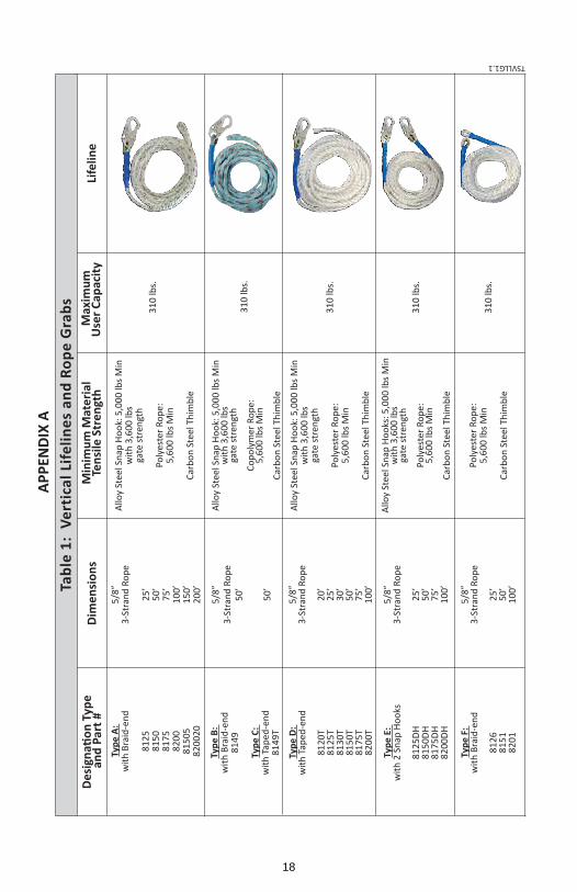
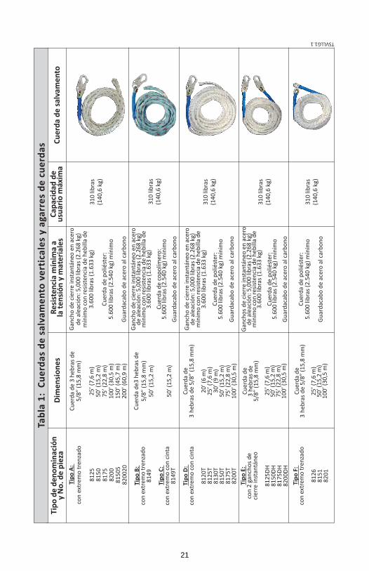
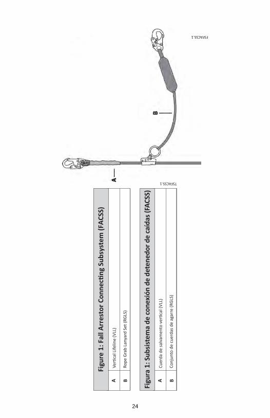
1. DESCRIPTION FallTech® single‐anchor Vertical Lifelines (VLL) are typically composed of a rope of various materials, lengths and end terminations. When a VLL is combined with connectors, a Shock Absorbing Lanyard (SAL), fall arrestors, (rope grabs) and a counter weight, it becomes a Fall Arrestor Connector Subsystem (FACSS). See Figure 1. A FACSS, combined with an anchorage and a Full Body Harness (FBH), form a Personal Fall Arrest System (PFAS). A PFAS is an assembly of components and subsystems used to arrest a person during a fall event. See Figure 2. For the purposes of this manual, the system may be referred to as the equipment, the unit or the device. All systems discussed in this manual are ANSI Z359.1‐2007 compliant and meet all OSHA regulations for fall protection. 1.1 Vertical Lifelines (VLL): VLLs are the vertical rope lifeline portion of a fall arrest or restraint system. VLL are available in many configurations, lengths and materials. All VLLs are 0.625 in. synthetic rope. VLLs are designated as Types, depending on construction, material and end configuration. When so equipped, VLL anchorage snap hooks are pre‐installed in plated steel thimbles. See Table 1 in Appendix A (all table and figure references are hereafter to Appendix A). A list of acronyms used in fall protection and fall arrest is provided in Appendix A.
Type A is polyester rope, with a snap hook and a braided end termination
Type B is a copolymer rope, with a snap hook and braided end termination.
Type C is a copolymer rope, with a snap hook and taped end termination.
Type D is polyester rope, with a snap hook and a taped end termination.
Type E is polyester rope with two snap hooks.
Type F is polyester rope with a plated steel thimble for use of a carabiner, and a braided end termination.
1.2 Rope Grabs and Rope Grab Lanyard Sets (RGLS): Rope grabs are steel mechanisms designed to allow worker mobility along the lifeline as the worker moves about. A spring‐loaded internal cam locks onto the VLL during a fall event, arresting the fall. Some grabs are sold separately.
2
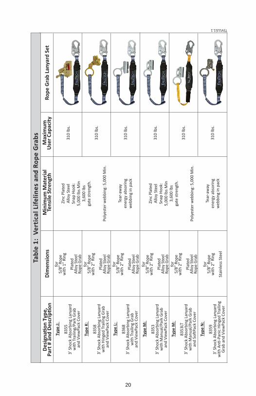
RGLS are composed of a rope grab attached to a SAL, which is permanently attached to a snap hook, configured to connect to an FBH. See Table 1. Rope grabs and RGLS are designated as Types.
Type G is a hinged grab without a lanyard. The grab consists of a large steel ring for attachment of a SAL, designed to function with a FallTech VLL. The Type G grab is a trailing type, (the grab will travel up and down the VLL hands‐free) and features a secondary safety latch.
Type H is a trailing grab without a lanyard. The grab has a large steel ring, with a hinged closure for a FallTech VLL, a secondary safety latch, a line guide and an anti‐panic locking cam.
Type J is an RGLS, comprised of a SAL, permanently attached to a trailing rope grab with safety lock, parking function and a two‐step hinged closure for a FallTech VLL.
Type K is an RGLS, comprised of a SAL permanently attached to a trailing rope grab with a safety lock, and a hinged closure for a FallTech VLL.
Type L is an RGLS, comprised of a SAL permanently attached to a non‐opening trailing rope grab.
Type M is an RGLSs, comprised of a SAL, permanently attached to a non‐opening, non‐trailing (manual) grab.
Type N is an RGLSs, comprised of a SAL, permanently attached to an anti‐panic trailing grab and a hinged closure for a FallTech VLL.
2. APPLICATION 2.1 Purpose: The systems and equipment discussed in this manual are intended for use as part of a PFAS or restraint system. 2.2 Personal Fall Arrest System: A VLL, combined with a fall arrestor (grab), and a SAL, forms a Fall Arrestor Connector Subsystem (FACSS). The FACSS, combined with an anchorage and an FBH, forms a PFAS, used to arrest the user during a fall event. Maximum permissible free fall is six feet. 2.3 Fall Restraint: The VLL, when used with a non‐trailing (manual) grab and designed and installed by a Competent Person, may be configured as a restraint system used in fall restraint, to prevent the user from reaching a fall hazard. No free fall is permitted. 2.4 Rescue, Positioning, Riding, Climbing: The VLL is not suited for rescue, positioning, riding or climbing applications. See ANSI Z359.4‐2007. 2.5 Application Limits: Take action to avoid sharp edges, abrasive surfaces, and thermal, electrical and chemical hazards.
3. SYSTEM REQUIREMENTS 3.1 Capacity: The rope grabs, connectors, VLLs, and SALs covered in this manual, which collectively comprise a PFAS, are ANSI Z359 compliant, with a listed total capacity, including clothing, tools, etc., of no more than 310 lbs., (140.6 kg), No more than one VLL may be connected to one anchorage device at one time. 3.2 Compatibility of Connectors: Connectors are considered to be compatible with connecting elements when they have been designed to work together in such a way that their sizes and shapes do not cause their gate mechanisms to inadvertently open regardless of how they become oriented. Contact FallTech if you have any questions about compatibility. Connectors must be compatible with the anchorage or other system components. Do not use equipment that is not compatible. Non‐compatible connectors may unintentionally disengage. Connectors must be compatible in size, shape, and strength. Self‐closing, self‐locking snap hooks and carabiners are specified by OSHA and ANSI.
3
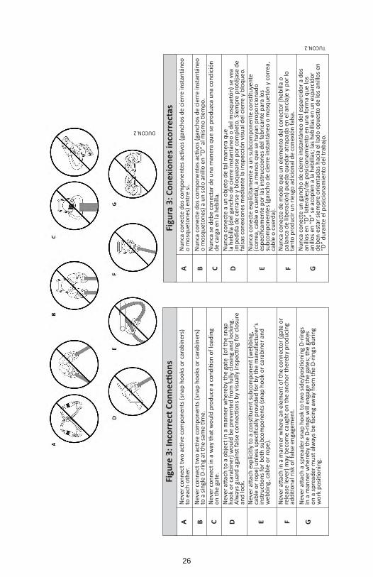
3.3 Compatibility of Components: Equipment is designed for use with approved components and subsystems only. Substitutions or replacements made with non‐approved components or subsystems may jeopardize compatibility of equipment and may affect the safety and reliability of the complete system. 3.4 Making Connections: Only use self‐locking snap hooks and carabiners with this equipment. Only use connectors that are suitable to each application. Ensure all connections are compatible in size, shape and strength. Do not use equipment that is not compatible. Visually ensure all connectors are fully closed and locked. Connectors (snap hooks and carabiners) are designed to be used only as specified in this manual. See Figure 3. DO NOT:
A. attach multiple snap hooks or carabiners to an anchorage. B. attach snap hooks or carabiners in a manner that may result in the gate being loaded. C. allow a false engagement, where features that protrude from the snap hook or
carabiner catch on the anchor. D. attach snap hooks or carabiners to each other. E. attach snap hooks or carabiners to webbing or rope lanyard or tie‐back (unless the
manufacturer’s instructions for both the lanyard and connector specifically allows such a connection).
F. attach snap hooks or carabiners to any object which is shaped or dimensioned such that the snap hook or carabiner will not close and lock, or that roll‐out could occur.
3.5 Personal Fall Arrest System: A PFAS is an assembly of components and subsystems used to arrest a person in a free fall. A PFAS is typically composed of an anchorage and an FBH, with a connecting device, i.e., a SAL, an SRD, or a FACSS attached to the dorsal D‐ring of the FBH. PFAS components used with this equipment must meet applicable ANSI Z359 requirements and OSHA regulations. OSHA requires a personal fall arrest system be able to arrest the user’s fall with a maximum arresting force of 1,800 lbs., and limit the free fall to 6 feet or less. If the maximum free fall distance must be exceeded, the employer must document, based on test data, that the maximum arresting force will not be exceeded, and the personal fall arrest system will function properly. 3.5.1 PFAS Anchorage Strength: An anchorage selected for PFAS must have a strength able to sustain a static load applied in the direction permitted by the PFAS of at least:
a) Two times the maximum arrest force permitted when certification exists, or b) 5,000 lbs. (22.2 kN) in the absence of certification.
3.6 Restraint System: Restraint systems are typically utilized to prevent the user from reaching a fall hazard area, and must meet OSHA regulations and ANSI standards. 3.6.1 Restraint Anchorage Strength: Anchorages selected for restraint, and travel restraint systems, shall have a strength able to sustain static loads applied in the directions permitted by the system of at least:
a) 3,000 lbs. (13.3 kN) for non‐certified anchorages, or b) two times the foreseeable force for certified anchorages.
3.7 Rescue: Rescue applications require specialized equipment and is beyond the scope of this manual. See ANSI Z359.4‐2007 3.8 Definitions: The following are definitions of terms. Authorized Person: A person assigned by the employer to perform duties at a location where the person will be exposed to a fall hazard (otherwise referred to as “user” for the purpose of these instructions). Certified Anchorage: An anchorage for fall arrest, positioning, restraint, or rescue systems that a Qualified Person certifies to be capable of supporting the potential fall forces that could be encountered during a fall or that meet the criteria for a certified anchorage prescribed in this standard.
4

Competent Person: One who is capable of identifying existing and predictable hazards in the surroundings or working conditions which are unsanitary, hazardous, or dangerous to employees, and who has authorization to take prompt corrective measures to eliminate them. Qualified Person: A person with a recognized degree or professional certificate and with extensive knowledge, training, and experience in the fall protection and rescue field who is capable of designing, analyzing, evaluating and specifying fall protection and rescue systems to the extent required by this standard. Rescuer: Person or persons other than the rescue subject acting to perform an assisted rescue by operation of a rescue system.
4. INSTALLATION AND OPERATION Installation of this FACSS must be under the supervision of a Competent Person trained in its design and use. DO NOT use any FACSS discussed in this manual until the system has been completely installed, inspected, and approved for use by a Competent Person. 4.1 Anchorage Location: Select a suitable anchorage point that will support the strength requirement and minimize free fall and swing hazards. Do not work above the anchorage point. 4.2 Fall Clearance Distance: When working at heights and using a PFAS, it is important to consider the distance between the walking/working level and the next lower level, or obstruction, to ensure there is sufficient room for the PFAS to arrest a fall. Fall Clearance Distance is the distance that is required to safely arrest the fall of a user. The Distance may be calculated by adding together the Length of the Lanyard, the Deceleration Distance, the Height of the Worker, plus a Safety Factor of 1 1/2’. Synthetic rope is subject to elongation, or stretch. As the distance between the anchorage and the grab increases, the portion of the VLL that is subjected to loads increases, thereby increasing the effects of elongation. Elongation can be as much as ten percent for rope in wet conditions. Consideration of elongation must be considered when estimating fall clearance distances. See Figure 4. 4.3 Swing Fall: Swing falls occur when the anchorage point is not directly above the point where a fall occurs. The force of striking an object in a swing fall may cause serious injury. In a swing fall, the total vertical fall distance will be greater than if the user had fallen directly below the anchorage point, thus increasing the total free fall distance and the area required to safely arrest the user. Minimize swing falls by working as directly below the anchorage point as possible. Move the anchorage as required. Never permit a swing fall if injury could occur. If a swing fall situation exists in your application consult a Competent Person before proceeding. See Figure 5. 4.4 Installation and Use of VLL, Rope Grabs and RGLS. This manual assumes the anchorage and the FBH is in compliance and has been previously installed and inspected by a Competent Person. VLLs, rope grabs and RGLS’ are components in a FACSS, but installation and use will be discussed separately. 4.4.1 VLL Type A – F: All VLLs are similar, but materials and end terminations will vary. The basic function is to provide a length of lifeline for the rope grab to travel on and grip to arrest fall events. All VLLs have a self‐closing and self‐locking snap hook pre‐installed in a thimbled eye at the anchorage end, with one exception, the Type F, which is without a snap hook and is configured for a carabiner. Attach the self‐closing self‐locking snap hook or carabiner to the anchorage. Attach a minimum five‐pound counter weight to the non‐anchorage end to maintain a taut line. Let the non‐anchorage end hang freely. If the rope passes over an edge of any kind, or any type of rough or uneven surface, provide abrasion protection. See Table 1.
5

4.4.2 Rope Grabs Type G – H, and RGLS, Type J – N NOTE: All rope grabs discussed herein have an UP arrow stamped in a prominent location. When installing a grab onto a VLL, visually ensure the UP arrow is pointed at the anchor end of the VLL. The grab must be right‐side up to fully close. Hinged opening grabs employ an anti‐inversion cam to prevent closure if installed upside down, with one exception. The grab in RGLS Type J does NOT employ an anti‐inversion device.
WARNING The grabs must be installed with the arrow pointing upward. If the grab is installed upside down
it WILL NOT LOCK during a fall event, which could result in injury or death. Rope Grab Type G
1. Locate the UP arrow indicator. See Figure 6. 2. To open the grab depress the safety latch and unscrew the knurled locking knob. 3. Lift the ring and cam assembly to retract the cam. Place the VLL in the channel,
opposite the cam. 4. Close the grab. 5. Depress the safety latch and tighten the knurled locking knob. 6. Connect the shock‐absorbing end of the lanyard to the FBH. Connect the non‐shock absorbing
end of the lanyard to the large ring of the grab. 7. Pull down on the ring and cam lever to ensure the grab locks onto the VLL. Rope Grab
Type G is a trailing type. If a fall event occurs, the grab will lock onto the VLL and arrest the fall.
Rope Grab Type H 1. Locate the UP arrow. See Figure 7. 2. Rotate the safety latch all the way up. Unscrew the knurled locking knob. Open the
hinged gate. 3. Lift the ring to retract the cam assembly. Place the VLL in the rope channel. Close the
gate. The grab utilizes an anti‐inversion cam in the hinge to prevent the grab from closing if incorrectly oriented. The grab must be right‐side up to close.
4. Screw the lock knob back in until tight. Rotate the safety latch all the way down. 5. Connect the non‐shock absorbing end of a SAL to the grab, and the shock‐absorbing
end to the FBH. See Section 3. 6. Rope Grab Type H is trailing type. In case of a fall, the lever will be pulled down, the
grab will lock onto the VLL, arresting the fall. RGLS Type J The Type J provides extensive operational and safety features. See Figure 8. Locate the Up Arrow, Cam Lever, Connector Stirrup, D‐Ring, Rope Channel, Locking Bolt Actuator, and Safety Latch, and on the opposite side, the Parking Lever.
1. Ensure the Up Arrow is pointed up, toward the VLL anchorage. 2. To open the hinged grab, hold it in your left hand. Raise the Safety Latch. 3. Hold the cam lever up, and push in and down on the Locking Bolt Actuator. The
Locking Bolt disengages from the bolt receiver. At the bottom of its travel, allow the actuator to rotate back slightly to engage the lock‐open tab in the lock‐open slot.
4. Place the VLL in the rope channel, close the hinge and press the bolt actuator in to release the lock‐open feature and allow the locking bolt to engage the lock receiver. Lower the safety latch.
5. The Type J grab is equipped with a parking feature. With the parking feature is engaged, the grab is prevented from traveling down the VLL rope but will still travel up toward the anchorage. When the parking feature is disengaged, the grab functions as a trailing grab. To engage the park feature, press the lever down and out. A spring
6
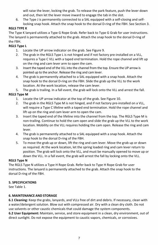
will raise the lever, locking the grab. To release the park feature, push the lever down and out, then let the lever move inward to engage the tab in the slot.
6. The Type J is permanently connected to a SAL equipped with a self‐closing and self‐locking snap hook. Attach the snap hook to the dorsal D‐ring of the FBH. See Section 3.
RGLS TYPE K The Type K lanyard utilizes a Type G Rope Grab. Refer back to Type G Grab for user instructions. The lanyard is permanently attached to the grab. Attach the snap hook to the dorsal D‐ring of the FBH. RGLS Type L
1. Locate the UP arrow indicator on the grab. See Figure 9. 2. The grab in the RGLS Type L is not hinged and if not factory pre‐installed on a VLL,
requires a Type C VLL with a taped end termination. Hold the rope channel and lift up on the ring and cam lever arm to open the cam.
3. Insert the taped end of the VLL into the channel from the top. Ensure the UP arrow is pointed up to the anchor. Release the ring and cam lever.
4. The grab is permanently attached to a SAL equipped with a snap hook. Attach the snap hook to the dorsal D‐ring on the FBH. Slide the grab up the VLL to the work location. At the work location, release the cam lever.
5. The grab is trailing. In a fall event, the grab will lock onto the VLL and arrest the fall. RGLS Type M
1. Locate the UP arrow indicator at the top of the grab. See Figure 10. 2. The grab in the RGLS Type M is not hinged, and if not factory pre‐installed on a VLL,
will require a Type C lifeline with a taped end termination. Hold the rope channel and lift up on the ring and cam lever arm to open the cam.
3. Insert the taped end of the lifeline into the channel from the top. The RGLS Type M is non‐trailing. Continue to hold the cam open and slide the grab up the VLL to the work location. Mobility on the VLL requires holding the cam open. Release the ring and cam lever.
4. The grab is permanently attached to a SAL equipped with a snap hook. Attach the snap hook to the dorsal D‐ring of the FBH.
5. To move the grab up or down, lift the ring and cam lever. Move the grab up or down as required. At the work location, let the spring loaded ring and cam lever return to position. The grab will lock onto the VLL, and must be manually opened to move up or down the VLL. In a fall event, the grab will arrest the fall by locking onto the VLL.
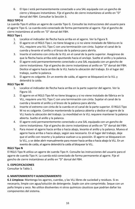
RGLS Type N The RGLS Type N utilizes a Type H Rope Grab. Refer back to Type H Rope Grab for user instructions. The lanyard is permanently attached to the grab. Attach the snap hook to the dorsal D‐ring of the FBH. 5. SPECIFICATIONS See Table 1. 6. MAINTENANCE AND STORAGE 6.1 Cleaning: Keep the grabs, lanyards, and VLLs free of dirt and debris. If necessary, clean with a water/detergent solution. Blow out with compressed air. Dry with a clean dry cloth. Do not use solvents or other caustic chemicals that could damage the system components. 6.2 User Equipment: Maintain, service, and store equipment in a clean, dry environment, out of direct sunlight. Do not expose the equipment to caustic vapors, chemicals, or corrosives.
7
6.3 Storage: Store in a clean, dry area. Avoid direct sunlight and contact with heat sources. Avoid exposure to environmental elements. Do not place other gear or objects on top of the equipment. 6.4 Remove From Service: Remove the equipment from service if it has been subjected to fall arrest forces or fails inspection. 7. INSPECTION Prior to each use, the user must inspect the system for any physical damage, wear, corrosion or missing parts. 7.1 Inspection Procedure: Check for the following:
1. Distortion of the rope, such as kinking, crushing, bird‐caging, strand displacement, etc. 2. Areas of weld strike or melting 3. General fraying 4. Reduction of the outer diameter of the rope due to wear or pinching 5. Evidence of any heat damage from any cause 6. Cut strands 7. Loosening of the tucks at the carabiner end splice
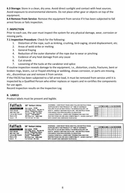
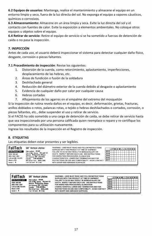
If routine inspection reveals damage to the equipment, i.e., distortion, cracks, fractures, bent or broken rings, levers, cut or frayed stitching or webbing, shows corrosion, or parts are missing, etc., discontinue use and remove it from service. If the FACSS has been subjected to a fall arrest load, it must be removed from service until it is inspected by a Qualified Person who either replaces or repairs and re‐certifies the components for use again. Record inspection results on the Inspection Log. 8. LABELS Product labels must be present and legible.
8
Manual de instrucciones para el usuario
Subsistemas de conexión de detenedor de caídas con un anclaje (FACSS).
Este manual está destinado a cumplir con las instrucciones del fabricante, según lo requerido por ANSI Z359 y debe utilizarse como parte de un programa de capacitación para empleados según se requiere por la OSHA. Este manual asume que el usuario ha sido capacitado en el uso de este equipo.
ADVERTENCIA Este producto es parte de un sistema personal de detención de caídas, de restricción, posicionamiento del trabajo, suspensión o de rescate. Un Sistema personal de detención de caídas (PFAS, por sus siglas en inglés) por lo general está compuesto de un anclaje y un Arnés de cuerpo completo (FBH, por sus siglas en inglés), con un dispositivo de conexión, es decir, una Cuerda de salvamento con amortiguación (SAL, por sus siglas en inglés), o un Dispositivo autorretráctil (SRD, por sus siglas en inglés), conectado al anillo en "D" dorsal del FBH. Estas instrucciones se deben proporcionar al usuario de este equipo. El usuario debe leer y comprender las instrucciones del fabricante para cada componente o parte del sistema completo. Las instrucciones del fabricante deben seguirse para el uso, cuidado y mantenimiento correctos de este producto. Estas instrucciones deben conservarse y mantenerse disponibles para consulta del usuario en todo momento. Las alteraciones o el uso indebido de este producto o no seguir las instrucciones pueden causar lesiones graves o la muerte. Un Plan de protección contra caídas debe estar archivado y disponible para su revisión por parte de todos los usuarios. El usuario y el comprador de este equipo tienen la responsabilidad de asegurarse de que los usuarios de este equipo están debidamente capacitados sobre su uso, mantenimiento y almacenamiento. La capacitación se debe repetir a intervalos regulares. La capacitación no debe someter a los usuarios a peligros de caídas. Cuando este equipo está en uso, el empleador debe tener un plan de rescate y los medios a la mano para implementarlo, y debe comunicar el plan a los usuarios, las personas autorizadas y al personal de rescate. Consulte a un médico si hay razones para dudar de su aptitud para absorber con seguridad el impacto de un evento de caída. La edad y el estado físico afectan gravemente a la capacidad de los trabajadores para soportar caídas. Las mujeres embarazadas y los menores de edad no deben utilizar este equipo. NOTA: Para obtener más información, consulte ANSI Z359.
FallTech 1306 South Alameda Street Compton, CA 90221, USA
1‐800‐719‐4619 1‐323‐752‐0066
www.falltech.com ©2013
9

ÍNDICE 1. DESCRIPCIÓN 1.1 Cuerdas de salvamento verticales (VLL) 1.2 Agarres de cuerda y Equipo de agarre de cordón/cuerda (RGLS) 2. APLICACIÓN 2.1 Objetivo 2.2 Sistema personal de detención de caídas 2.3 Restricción contra caídas 2.4 Rescate, posicionamiento, montaje, escalada 2.5 Límites de la aplicación 3. REQUISITOS DEL SISTEMA 3.1 Capacidad 3.2 Compatibilidad de conectores 3.3 Compatibilidad de componentes 3.4 Realizar las conexiones 3.5 Sistema personal de detención de caídas 3.5.1 Resistencia del anclaje del PFAS 3.6 Sistema de restricción 3.6.1 Resistencia del anclaje de restricción
3.7 Rescate 3.8 Definiciones 4. INSTALACIÓN Y OPERACIÓN 4.1 Ubicación del anclaje 4.2 Distancia de caída despejada 4.3 Caída con balanceo 4.4 Instalación y uso de VLL, agarres de cuerdas y RGLS
4.4.1 VLL Tipo A ‐ F 4.4.2 Agarres de cuerdas Tipo G ‐ H, y RGLS, Tipo J ‐ N
5. ESPECIFICACIONES 6. MANTENIMIENTO Y ALMACENAMIENTO 6.1 Limpieza 6.2 Equipos de usuarios 6.3 Almacenamiento 6.4 Retirar de servicio 7. INSPECCIÓN 7.7 Procedimiento de inspección 8. ETIQUETAS APÉNDICE A Tabla 1, Lista de siglas, Figuras 1‐10, Registro de inspección
1. DESCRIPCIÓN Las Cuerdas de salvamento verticales (VLL) de un anclaje de FallTech® por lo general están compuestas por una cuerda de diversos materiales, longitudes y terminaciones finales. Cuando se combina una VLL con los conectores, una Cuerda de salvamento con amortiguación (SAL), detenedores de caídas, (agarres de cuerdas) y un contrapeso, se convierte en un Subsistemas de conexión de detenedor de caídas (FACSS, por sus siglas en inglés). Ver la Figura 1. Un FACSS, combinado con un anclaje y un arnés de cuerpo completo (FBH, por sus siglas en inglés), forman un Sistema personal de detención de caídas (PFAS, por sus siglas en inglés). El PFAS es un conjunto de componentes y subsistemas utilizados para detener a una persona durante un evento de caída. Ver la Figura 2. Para los efectos de este manual, el sistema se puede denominar como el equipo, la unidad o el dispositivo. Todos los sistemas descritos en este manual son compatibles con ANSI Z359.1‐2007 y cumplen con todos los reglamentos sobre protección contra caídas de la OSHA. 1.1 Cuerdas de salvamento verticales (VLL): Las VLL son la parte de la cuerda de salvamento vertical de un sistema de detención de caídas o sistema de restricción. Las VLL están disponibles en muchas configuraciones, longitudes y materiales. Todas las VLL son una cuerda sintética de 0,625 pulgadas (1,6 cm). Las VLL están designadas por tipos, en función de la construcción, materiales y configuración de los extremos. Cuando están equipados con éstas, los ganchos de cierre instantáneo del anclaje de la VLL están pre‐instalados en guardacabos en acero chapado. Consulte la Tabla 1 en el Apéndice A (todas las referencias de figuras y tablas se encuentran en el Apéndice A). La lista de siglas utilizadas en protección contra caídas y detención de caídas se proporciona en el Apéndice A.
El Tipo A es una cuerda de poliéster, con un gancho de cierre instantáneo y una terminación trenzada.
10

El Tipo B es una cuerda de copolímero, con un gancho de cierre instantáneo y una terminación trenzada.
El Tipo C es una cuerda de copolímero, con un gancho de cierre instantáneo y una terminación con cinta.
El Tipo D es una cuerda de poliéster, con un gancho de cierre instantáneo y una terminación con cinta.
El Tipo E es cuerda de poliéster con dos ganchos de cierre instantáneo.
El Tipo F es una cuerda de poliéster con un guardacabo en acero chapado para utilizar con un mosquetón, y una terminación trenzada.
1.2 Agarres de cuerda y Equipo de agarre de cordón/cuerda (RGLS): Los agarres de cuerdas son mecanismos de acero diseñados para permitir la movilidad del trabajador a lo largo de la cuerda a medida que el trabajador se mueve. Una palanca interna con resorte se bloquea en la VLL durante un evento de caída, con lo cual se detiene la caída. Algunos agarres se venden por separado. El RGLS está compuesto por un agarre de cuerda conectado a una SAL, la cual está permanentemente conectada a un gancho de cierre instantáneo, configurado para conectarse a un FBH. Consultar la Tabla 1. Los agarres de cuerdas y los RGLS están designados por Tipos.
El Tipo G es un agarre con bisagra sin una cuerda. El agarre consiste en un anillo de acero grande para la conexión de una SAL, diseñado para funcionar con una VLL de FallTech. El agarre de Tipo G es de tipo colgante (el agarre se desplazará hacia arriba y hacia abajo en la VLL con las manos libres) y tiene un pestillo de seguridad secundario.
El Tipo H es un agarre colgante sin una cuerda. El agarre tiene un anillo grande de acero, con un cierre con bisagra para una VLL de FallTech, un pestillo de seguridad secundario, una línea guía y una palanca de bloqueo anti‐pánico.
El Tipo J es un RGLS, el cual consta de una SAL, conectada permanentemente a un agarre de cuerda colgante con un bloqueador de seguridad, una función de detención y un cierre con bisagra de dos pasos para una VLL de FallTech.
El Tipo K es un RGLS, el cual consta de una SAL, conectada permanentemente a un agarre de cuerda colgante con un bloqueador de seguridad y un cierre con bisagra para una VLL de FallTech.
El Tipo L es un RGLS, compuesto de una SAL conectada permanentemente a un agarre de cuerda colgante sin apertura.
El Tipo M es un RGLS, compuesto de una SAL conectada permanentemente a un agarre de cuerda no colgante sin apertura (manual).
El Tipo N es un RGLS, el cual consta de una SAL, conectada permanentemente a un agarre colgante anti‐pánico y un cierre con bisagra para una VLL de FallTech.
2. APLICACIÓN 2.1 Objetivo: Los sistemas y equipos mencionados en este manual están destinados a ser utilizados como parte de un PFAS o un sistema de restricción. 2.2 Sistema personal de detención de caídas: Una VLL, combinada con un detenedor de caídas (agarre), y una SAL, forman un Subsistema de conexión de detenedor de caídas (FACSS, por sus siglas en inglés). El FACSS, combinado con un anclaje y un FBH, forman un PFAS, utilizado para detener al usuario durante un evento de caída. La caída libre máxima permitida es de seis pies (1,8 m). 2.3 Restricción contra caídas: La VLL, cuando se utiliza con un agarre no colgante (manual) y cuando es diseñada e instalada por una persona competente, puede ser configurada como un sistema de restricción contra caídas, para evitar que el usuario llegue a un peligro de caída. No se permite la caída libre.
11

2.4 Rescate, posicionamiento, montaje, escalada: La VLL no es apta para aplicaciones de rescate, posicionamiento, montaje o escalada. Consultar ANSI Z359.4‐2007. 2.5 Límites de la aplicación: Tome medidas para evitar los bordes afilados, superficies abrasivas y peligros térmicos, eléctricos y químicos. 3. REQUISITOS DEL SISTEMA 3.1 Capacidad: Los agarres de las cuerdas, conectores, las VLL y las SAL cubiertos en este manual, los cuales en conjunto componen a un PFAS, cumplen con ANSI Z359, con una capacidad total nominal, incluyendo ropa, herramientas, etc., de no más de 310 libras (140,6 kg). No más de una VLL puede estar conectada a un dispositivo de anclaje a la vez. 3.2 Compatibilidad de conectores: Los conectores son considerados compatibles con elementos de conexión cuando se han diseñado para funcionar en conjunto, de manera que sus formas y tamaños no causen que sus mecanismos de compuerta se abran inadvertidamente, de manera independiente a la forma en que queden orientados. Comuníquese con FallTech si tiene alguna pregunta acerca de la compatibilidad. Los conectores deben ser compatibles con el anclaje u otros componentes del sistema. No utilice el equipo que no sea compatible. Los conectores no compatibles pueden soltarse accidentalmente. Los conectores deben ser compatibles en tamaño, forma y resistencia. Los mosquetones y ganchos de cierre y bloqueo automático son requeridos por ANSI y la OSHA. 3.3 Compatibilidad de componentes: El equipo está diseñado para su uso sólo con componentes y subsistemas aprobados. Las sustituciones o reemplazos realizados con componentes o subsistemas no aprobados pueden poner en peligro la compatibilidad de los equipos y pueden afectar a la seguridad y la fiabilidad del sistema completo. 3.4 Realizar las conexiones: Utilice sólo mosquetones y ganchos de cierre automático con este equipo. Utilice sólo los conectores que son adecuados para cada aplicación. Asegúrese de que todas las conexiones son compatibles en tamaño, forma y resistencia. No utilice el equipo que no sea compatible. Asegúrese visualmente de que todos los conectores están completamente cerrados y bloqueados. Los conectores (mosquetones y ganchos de cierre automático) están diseñados para ser usados sólo como se indica en este manual. Ver la Figura 3. NO:
A. conecte varios mosquetones o ganchos de cierre automático a un anclaje. B. conecte los mosquetones o ganchos de cierre automático de manera que puedan
causar la carga de la compuerta. C. permita una falsa conexión, donde los elementos que sobresalen del mosquetón o gancho de
cierre instantáneo se enganchen en el anclaje. D. conecte los mosquetones o ganchos de cierre automático entre sí. E. conecte los mosquetones o ganchos de cierre automático a la correa, cordón o amarre
posterior (a menos que las instrucciones del fabricante para el cordón y el conector permitan específicamente ese tipo de conexión).
F. fije mosquetones o ganchos de cierre automático a cualquier objeto que tenga una forma o dimensión la cual no permita que el mosquetón o gancho se cierre y bloquee, o que pueda ocurrir un rodamiento.
3.5 Sistema personal de detención de caídas: El PFAS es un conjunto de componentes y subsistemas utilizados para detener a una persona durante una caída libre. Un Sistema personal de detención de caídas (PFAS, por sus siglas en inglés) por lo general está compuesto de un anclaje y un Arnés de cuerpo completo (FBH, por sus siglas en inglés), con un dispositivo de conexión, es decir, una Cuerda de salvamento con amortiguación (SAL, por sus siglas en inglés), o un Dispositivo autorretráctil (SRD, por sus siglas en inglés), o un Subsistema de conexión de detenedor de caídas (FACSS, por sus siglas en inglés), conectado al anillo en "D" dorsal del FBH. Los componentes del PFAS utilizado con este equipo deben cumplir con los requisitos de ANSI Z359 y los reglamentos de la OSHA. La OSHA exige el uso del sistema personal de detención de
12

caídas para detener la caída del usuario con una fuerza máxima de detención de 1.800 libras (816,5 kg), y para limitar la caída libre a 6 pies (1,8 m) o menos. Si se debe exceder la distancia máxima de caída libre, el empleador debe documentar, con base en los datos de prueba, que no se excederá de la fuerza máxima de detención, y que el sistema personal de detención de caídas funcionará correctamente. 3.5.1 Resistencia del anclaje del PFAS: El anclaje seleccionado para el PFAS debe tener una resistencia capaz de sostener una carga estática aplicada en la dirección permitida por el PFAS de al menos:
a) dos veces el máximo de fuerza de detención permitida cuando exista la certificación, o b) 5.000 libras (2.268 kg) (22.2 kN) en ausencia de la certificación.
3.6 Sistema de restricción: Los sistemas de restricción se utilizan por lo general para evitar que el usuario llegue a un área de peligro de caída, y deben cumplir con los reglamentos de OSHA y ANSI. 3.6.1 Resistencia del anclaje de restricción: Los anclajes seleccionados de restricción, y los sistemas de restricción del recorrido, deberán tener una resistencia capaz de sostener cargas estáticas aplicadas en las direcciones permitidas por el sistema de al menos:
a) 3.000 libras (1.360,8 kg) (13.3 kN) para los anclajes que no tengan certificación, o b) dos veces la fuerza previsible para los anclajes certificados.
3.7 Rescate: Las aplicaciones de rescate requieren de equipos especializados que están más allá del alcance de este manual. Consultar ANSI Z359.4‐2007. 3.8 Definiciones: Las siguientes son las definiciones de los términos. Persona autorizada: Una persona asignada por el empleador para realizar sus obligaciones en un lugar donde la persona estará expuesta a un peligro de caída (de lo contrario, se denomina como "usuario" a los efectos de estas instrucciones). Anclaje certificado: Un anclaje para detención de caídas, posicionamiento, restricción, o sistemas de rescate que una persona calificada certifica de que puede soportar las posibles fuerzas de caída, las cuales podrían presentarse durante una caída o que cumplen con los criterios para un anclaje certificado previsto en la norma. Persona competente: Una persona que es capaz de identificar los peligros existentes y predecibles en los alrededores o condiciones de trabajo que son insalubres o peligrosas para los empleados, y quien tiene la autorización para tomar con prontitud medidas correctivas para eliminarlos. Persona calificada: Una persona con un título o certificado profesional reconocido y con amplios conocimientos, capacitación y experiencia en la protección contra caídas y el campo de rescate, quien es capaz de diseñar, analizar, evaluar y especificar los sistemas de protección contra caídas y sistemas de rescate en la medida exigida por la norma. Socorrista: Persona o personas distintas al sujeto que actúa en la realización de un rescate asistido por la operación de un sistema de rescate. 4. INSTALACIÓN Y OPERACIÓN La instalación del FACSS debe estar bajo la supervisión de una Persona competente, capacitada en su diseño y uso. NO utilice cualquier FACSS descrito en este manual hasta que el sistema se haya instalado, inspeccionado, y aprobado por completo para su uso por parte de una Persona competente. 4.1 Ubicación del anclaje: Seleccione un punto de anclaje adecuado para apoyar el requisito de resistencia y minimizar los peligros de caída libre y balanceo. No trabaje por encima del punto de anclaje. 4.2 Distancia de caída despejada: Cuando se trabaja en alturas y utilizando un PFAS, es importante considerar la distancia entre el nivel para caminar/de trabajo y el siguiente nivel inferior, u obstrucción, para asegurar que hay suficiente espacio para que el PFAS detenga la
13

caída. La distancia de caída despejada es la distancia necesaria para detener con seguridad la caída de un usuario. La distancia se puede calcular al sumar la longitud de la cuerda, la distancia de desaceleración, la altura del trabajador más un factor de seguridad de 1 1/2 pies (0,5 m). La cuerda sintética está sujeto a elongación o estiramiento. A medida que aumenta la distancia entre el anclaje y el agarre, la parte de la VLL que está sometida a cargas aumenta, y por lo tanto aumenta los efectos de elongación. La elongación puede ser tanto como diez por ciento para la cuerda en condiciones húmedas. La elongación debe ser considerada cuando se estiman las distancias de caída despejada. Ver la Figura 4. 4.3 Caída con balanceo: La caída con balanceo se produce cuando el punto de anclaje no está directamente por encima del punto donde ocurre la caída. La fuerza de golpear un objeto en una caída con balanceo puede causar lesiones graves. En una caída con balanceo, la distancia total de caída vertical será mayor a cuando el usuario ha caído directamente por debajo del punto de anclaje, lo cual aumenta la distancia total de caída libre y el área necesaria para detener al usuario con seguridad. Minimice las caídas con balanceo al trabajar lo más directamente posible por debajo del punto de anclaje. Mueva el anclaje según sea necesario. Nunca permita una caída con balanceo si puede ocurrir una lesión. Si hay una situación de caída con balanceo en su aplicación consulte a una persona competente antes de continuar. Ver la Figura 5. 4.4 Instalación y uso de VLL, agarres de cuerdas y RGLS Este manual asume que el anclaje y el FBH cumplen con las especificaciones y se han instalado e inspeccionado previamente por parte de una Persona competente. Las VLL, los agarres de cuerda y los RGLS son los componentes de un FACSS, pero la instalación y su uso se analizarán por separado. 4.4.1 VLL Tipo A ‐ F: Todas las VLL son similares, pero los materiales y las terminaciones finales pueden variar. La función básica es proporcionar una longitud de cuerda de salvamento para el agarre de la cuerda para recorrer y brindar agarre para detener los eventos de caídas. Todas las VLL tienen un gancho de cierre y bloqueo instantáneo pre‐instalado en un ojal de guardacabos en el extremo del anclaje, con una excepción, el Tipo F, el cual no tiene el gancho de cierre instantáneo y está configurado para un mosquetón. Conecte el gancho de cierre y bloqueo instantáneo o mosquetón al anclaje. Conecte un mínimo de contrapeso de cinco libras (2,3 kg) al extremo que no tiene anclaje para mantener una línea tensa. Deje que el extremo que no tiene anclaje cuelgue libremente. Si la cuerda pasa por encima de un borde de cualquier tipo, o cualquier tipo de superficie irregular o desigual, proporcione protección contra la abrasión. Consultar la Tabla 1. 4.4.2 Agarres de cuerdas Tipo G ‐ H, y RGLS, Tipo J ‐ N NOTA: Todas las cuerdas analizadas en el presente tienen una flecha con dirección hacia arriba estampada en un lugar destacado. Cuando instala un agarre en una VLL, asegúrese visualmente de que la flecha hacia arriba está señalando al extremo del anclaje de la VLL. El agarre debe estar del lado lateral derecho hasta cerrarse completamente. Los agarres con aberturas y bisagras tienen una palanca anti‐inversión para evitar el cierre si se instala al revés, con una excepción. El agarre en el RGLS Tipo J NO utiliza un dispositivo anti‐inversión.
ADVERTENCIA Los agarres deben ser instalados con la flecha apuntando hacia arriba. Si el agarre está
instalado hacia abajo, NO SE BLOQUEARÁ durante un evento de caída, lo cual podría resultar en lesiones o la muerte.
Agarre de cuerda Tipo G 1. Localice el indicador de la flecha hacia arriba. Ver la Figura 6. 2. Para abrir el agarre, presione el pestillo de seguridad y afloje el pomo de bloqueo.
14
3. Levante el anillo y el ensamblaje de la palanca para retraerla. Coloque la VLL en el canal, del lado opuesto de la palanca.
4. Cierre el agarre. 5. Presione el pestillo de seguridad y apriete el pomo de bloqueo. 6. Conecte el extremo con amortiguación de la cuerda al FBH. Conecte el extremo sin
amortiguación de la cuerda al anillo grande del agarre. 7. Hale hacia abajo del anillo y la palanca para asegurarse de que el agarre se bloquea en la
VLL. La cuerda de agarre Tipo G es del tipo colgante. Si se produce un evento de caída, el agarre se bloqueará en la VLL y detendrá la caída.
Agarre de cuerda Tipo H 1. Localice la flecha hacia arriba. Ver la Figura 7. 2. Gire el pestillo de seguridad completamente hacia arriba. Afloje la perilla de bloqueo.
Abra la compuerta con bisagras. 3. Levante el anillo para retraer el ensamblaje de la palanca. Coloque la VLL en el canal
de la cuerda. Cierre la compuerta. El agarre utiliza una palanca anti‐inversión en la bisagra para evitar que el agarre se cierre si está mal orientado. El agarre debe estar del lado lateral derecho hasta cerrarse.
4. Atornille la perilla de bloqueo hasta que quede apretado. Gire el pestillo de seguridad completamente hacia abajo.
5. Conecte el extremo sin amortiguación de la SAL al agarre, y el extremo con amortiguación al FBH. Consultar la Sección 3.
6. La cuerda de agarre Tipo H es del tipo colgante. En el caso de una caída, la palanca se empujará hacia abajo, y el agarre se bloqueará en la VLL, con lo cual se detendrá la caída.
RGLS Tipo J El Tipo J ofrece funciones amplias de seguridad y operación. Ver la Figura 8. Localice la flecha hacia arriba, la palanca, el estribo del conector, el anillo en "D", el canal de la cuerda, el actuador del perno de bloqueo, y el pestillo de seguridad, y en el lado opuesto, la palanca de detención.
1. Asegúrese de que la flecha hacia arriba esté apuntando hacia arriba, hacia el anclaje de la VLL.
2. Para abrir el agarre con bisagra, sosténgalo en la mano izquierda. Levante el pestillo de seguridad.
3. Mantenga la palanca hacia arriba, y presione hacia adentro y hacia abajo en el actuador del perno de bloqueo. El perno de bloqueo se desconecta del receptor del perno. En la parte inferior de su recorrido, permita que el actuador gire un poco hacia atrás para conectar la pestaña de apertura en la ranura de apertura.
4. Coloque la VLL en el canal en la cuerda, cierre la bisagra y presione el actuador del perno para liberar la función de bloqueo y permitir que el perno de bloqueo se conecte al receptor de bloqueo. Baje el pestillo de seguridad.
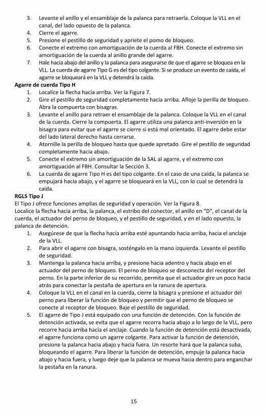
5. El agarre de Tipo J está equipado con una función de detención. Con la función de detención activada, se evita que el agarre recorra hacia abajo a lo largo de la VLL, pero recorre hacia arriba hacia el anclaje. Cuando la función de detención está desactivada, el agarre funciona como un agarre colgante. Para activar la función de detención, presione la palanca hacia abajo y hacia fuera. Un resorte hará que la palanca suba, bloqueando el agarre. Para liberar la función de detención, empuje la palanca hacia abajo y hacia fuera, y luego deje que la palanca se mueva hacia dentro para enganchar la pestaña en la ranura.
15
6. El tipo J está permanentemente conectado a una SAL equipada con un gancho de cierre y bloqueo instantáneo. Fije el gancho de cierre instantáneo al anillo en "D" dorsal del FBH. Consultar la Sección 3.
RGLS TIPO K La cuerda Tipo K utiliza un agarre de cuerda Tipo G. Consulte las instrucciones del usuario para el agarre Tipo G. La cuerda está conectado de forma permanente al agarre. Fije el gancho de cierre instantáneo al anillo en "D" dorsal del FBH. RGLS Tipo L
1. Localice el indicador de flecha hacia arriba en el agarre. Ver la Figura 9. 2. El agarre en el RGLS Tipo L no tiene bisagras y si no viene instalado de fábrica en la
VLL, requiere una VLL Tipo C con una terminación con cinta. Sujetar el canal de la cuerda y levante el anillo y el brazo de la palanca para abrirla.
3. Inserte el extremo con cinta de la VLL en el canal de la parte superior. Asegúrese de que la flecha hacia arriba esté apuntando hacia el anclaje. Suelte el anillo y la palanca.
4. El agarre está permanentemente conectado a una SAL equipada con un gancho de cierre instantáneo. Fije el gancho de cierre instantáneo al anillo en "D" dorsal del FBH. Deslice el agarre hacia arriba de la VLL hasta la ubicación del trabajo. En el lugar del trabajo, suelte la palanca.
5. El agarre es colgante. En un evento de caída, el agarre se bloqueará en la VLL y detendrá la caída.
RGLS Tipo M 1. Localice el indicador de flecha hacia arriba en la parte superior del agarre. Ver la
Figura 10. 2. El agarre en el RGLS Tipo M no tiene bisagras y si no viene instalado de fábrica en la
VLL, requiere una VLL Tipo C con una terminación con cinta. Sujetar el canal de la cuerda y levante el anillo y el brazo de la palanca para abrirla.
3. Inserte el extremo con cinta de la cuerda en el canal de la parte superior. El RGLS Tipo M no es colgante. Continúe manteniendo la palanca abierta y deslice el agarre de la VLL hasta la ubicación del trabajo. La movilidad en la VLL requiere mantener la palanca abierta. Suelte el anillo y la palanca.
4. El agarre está permanentemente conectado a una SAL equipada con un gancho de cierre instantáneo. Fije el gancho de cierre instantáneo al anillo en "D" dorsal del FBH.
5. Para mover el agarre hacia arriba o hacia abajo, levante el anillo y la palanca. Mueva el agarre hacia arriba o hacia abajo, según sea necesario. En el lugar del trabajo, deje que el anillo con resorte y la palanca vuelvan a su posición. El agarre se bloqueará en la VLL, y se debe abrir manualmente para mover hacia arriba o hacia abajo la VLL. En un evento de caída, el agarre detendrá la caída al bloquear la VLL.
RGLS Tipo N El RGLS Tipo N utiliza un agarre de cuerda Tipo H. Consulte las instrucciones del usuario para el agarre de cuerda Tipo H. La cuerda está conectado de forma permanente al agarre. Fije el gancho de cierre instantáneo al anillo en "D" dorsal del FBH.
5. ESPECIFICACIONES Consultar la Tabla 1. 6. MANTENIMIENTO Y ALMACENAMIENTO 6.1 Limpieza: Mantenga los agarres, cuerdas, y las VLL libres de suciedad y residuos. Si es necesario, limpie con agua/solución de detergente. Sople con aire comprimido. Seque con un paño limpio y seco. No utilice disolventes ni otros químicos cáusticos que podrían dañar los componentes del sistema.
16
6.2 Equipos de usuarios: Mantenga, realice el mantenimiento y almacene el equipo en un entorno limpio y seco, fuera de la luz directa del sol. No exponga el equipo a vapores cáusticos, químicos o corrosivos. 6.3 Almacenamiento: Almacene en un área limpia y seca. Evite la luz directa del sol y el contacto con fuentes de calor. Evite la exposición a elementos ambientales. No coloque otros equipos u objetos sobre el equipo. 6.4 Retirar de servicio: Retire el equipo de servicio si se ha sometido a fuerzas de detención de caída o no pasa la inspección. 7. INSPECCIÓN Antes de cada uso, el usuario deberá inspeccionar el sistema para detectar cualquier daño físico, desgaste, corrosión o piezas faltantes. 7.1 Procedimiento de inspección: Revise los siguientes:
1. Distorsión de la cuerda, como retorcimiento, aplastamiento, imperfecciones, desplazamiento de las hebras, etc.
2. Áreas de fundición o fusión de la soldadura 3. Deshilachado general 4. Reducción del diámetro exterior de la cuerda debido al desgaste o aplastamiento 5. Evidencia de cualquier daño por calor por cualquier causa 6. Hebras cortadas 7. Aflojamiento de los agarres en el empalme del extremo del mosquetón
Si la inspección de rutina revela daños en el equipo, es decir, deformación, grietas, fracturas, anillos doblados o rotos, palancas rotas, o tejido o hebras deshilachados o cortados, corrosión, o piezas faltantes, etc., debe suspender el uso y retirar de servicio. Si el FACSS ha sido sometido a una carga de detención de caída, se debe retirar de servicio hasta que sea inspeccionado por una persona calificada quien reemplace o repare y re‐certifique los componentes para su utilización nuevamente. Ingrese los resultados de la inspección en el Registro de inspección. 8. ETIQUETAS Las etiquetas deben estar presentes y ser legibles.
17
APPE
NDI
X A
TSVLLG1.1
Type
A:
with
Bra
id-e
nd
8125
8150
8175
8200
8150
582
0020
Type
D:
with
Tap
ed-e
nd
8120
T81
25T
8130
T81
50T
8175
T 82
00T
Type
E:
with
2 S
nap
Hook
s
8125
DH81
50DH
8175
DH82
00DH
Type
F:
with
Bra
id-e
nd
8126
8151
8201
Type
B:
with
Bra
id-e
nd81
49
Type
C:
with
Tap
ed-e
nd81
49T
5/8”
3-
Stra
nd R
ope
25’
50’
75’
100’
150’
200’
5/8”
3-
Stra
nd R
ope
20’
25’
30’
50’
75’
100’
5/8”
3-
Stra
nd R
ope
25’
50’
75’
100’
5/8”
3-
Stra
nd R
ope
25’
50’
100’
5/8”
3-
Stra
nd R
ope
50’
50’
Allo
y St
eel S
nap
Hook
: 5,0
00 lb
s Min
w
ith 3
,600
lbs
gate
stre
ngth
Poly
este
r Rop
e:5,
600
lbs M
in
Carb
on S
teel
Thi
mbl
e
Allo
y St
eel S
nap
Hook
: 5,0
00 lb
s Min
w
ith 3
,600
lbs
gate
stre
ngth
Poly
este
r Rop
e:5,
600
lbs M
in
Carb
on S
teel
Thi
mbl
e
Allo
y St
eel S
nap
Hook
s: 5
,000
lbs M
in
with
3,6
00 lb
s ga
te st
reng
th
Poly
este
r Rop
e:5,
600
lbs M
in
Carb
on S
teel
Thi
mbl
e
Poly
este
r Rop
e:
5,60
0 lb
s Min
Carb
on S
teel
Thi
mbl
e
Allo
y St
eel S
nap
Hook
: 5,0
00 lb
s Min
w
ith 3
,600
lbs
gate
stre
ngth
Copo
lym
er R
ope:
5,60
0 lb
s Min
Carb
on S
teel
Thi
mbl
e
Life
line
Desi
gnati
on T
ype
and
Par
t #
Dim
ensi
ons
Min
imum
Mat
eria
l Te
nsile
Str
engt
h M
axim
umU
ser C
apac
ity
310
lbs.
310
lbs.
310
lbs.
310
lbs.
310
lbs.
Tabl
e 1:
Ver
tica
l Life
lines
and
Rop
e G
rabs
18

Type
G:
7479
Zinc
Pla
ted
Allo
y St
eel
Type
H:
7491
Stai
nles
s Ste
el
for 5
/8”
Rope
w
ith
2”
con
nec
tio
n r
ing
for 5
/8”
Rope
w
ith
2”
con
nec
tio
n r
ing
Hing
ed T
raili
ng d
esig
nan
d Se
cond
ary
Safe
ty L
atch
An
ti-P
anic
wit
h
Hing
ed T
raili
ng d
esig
n,
and
Seco
ndar
y Sa
fety
Lat
ch
Rope
Gra
bDe
sign
ation
Typ
e,
Part
# a
nd M
ater
ial
Dim
ensi
ons
Desc
riptio
nM
axim
um U
ser
Capa
city
and
M
inim
um T
ensi
le
Stre
ngth
310
lbs.
3,60
0 lb
s
310
lbs.
3,60
0 lb
s
TSVLLG1.1
Tabl
e 1:
Ver
tica
l Life
lines
and
Rop
e G
rabs
19
TSVLLG1.1
Type
J:
8355
3’ S
hock
Abs
orbi
ng L
anya
rdw
ith T
raili
ng/P
ark
Grab
and
View
Pack
Cov
er
Type
M:
8353
3’
Sho
ck A
bsor
bing
Lan
yard
with
Man
ual/P
ark
Grab
and
View
Pack
Cov
er
Type
K:
8358
3’ S
hock
Abs
orbi
ng L
anya
rdw
ith H
inge
d Tr
ailin
g Gr
aban
d Vi
ewPa
ck C
over
Type
M:
8353
LT3’
Sho
ck A
bsor
bing
Lan
yard
with
Man
ual/P
ark
Grab
and
So
ftPa
ck C
ove
r
Type
L:
8368
3’ S
hock
Abs
orbi
ng L
anya
rdw
ith T
raili
ng G
rab
and
View
Pack
Cov
er
Type
N:
8359
3’ S
hock
Abs
orbi
ng L
anya
rdw
ith
An
ti-P
anic
Hin
ged
Tra
ilin
g Gr
ab a
nd V
iew
Pack
Cov
er
for
5/8”
Rop
e w
ith 1
” Ri
ng
Plat
ed
Allo
y St
eel
Rope
Gra
b
for
5/8”
Rop
e w
ith 2
” Ri
ng
Plat
ed
Allo
y St
eel
Rope
Gra
b
for
5/8”
Rop
e w
ith 2
” Ri
ng
Plat
ed
Allo
y St
eel
Rope
Gra
b
for
5/8”
Rop
e w
ith 2
” Ri
ng
Plat
ed
Allo
y St
eel
Rope
Gra
b
for
5/8”
Rop
e w
ith 2
” Ri
ng
Plat
ed
Allo
y St
eel
Rope
Gra
b
for
5/8”
Rop
e w
ith 2
” Ri
ng
Stai
nles
s Ste
el
Rope
Gra
b La
nyar
d Se
tDe
sign
ation
Typ
e,Pa
rt #
and
Des
crip
tion
Dim
ensi
ons
Min
imum
Mat
eria
l Te
nsile
Str
engt
h M
axim
umU
ser C
apac
ity
310
lbs.
310
lbs.
310
lbs.
310
lbs.
310
lbs.
310
lbs.
Tabl
e 1:
Ver
tica
l Life
lines
and
Rop
e G
rabs
Zinc
Pla
ted
Allo
y St
eel
Snap
Hoo
k:
5,00
0 lb
s Min
3,
600
lbs
gate
stre
ngth
.
Poly
este
r web
bing
: 5,0
00 M
in.
Tear
-aw
ay
ener
gy a
bsor
ing
web
bing
in p
ack
Zinc
Pla
ted
Allo
y St
eel
Snap
Hoo
k:
5,00
0 lb
s Min
3,
600
lbs
gate
stre
ngth
.
Poly
este
r web
bing
: 5,0
00 M
in.
Tear
-aw
ay
ener
gy a
bsor
ing
web
bing
in p
ack
20
TSVLLG1.1
Tipo
A:
con
extr
emo
tren
zado
8125
8150
8175
8200
8150
582
0020
Tipo
D:
con
extr
emo
con
cint
a
8120
T81
25T
8130
T81
50T
8175
T 82
00T
Tipo
E:
con
2 ga
ncho
s de
cier
re in
stan
táne
o
8125
DH81
50DH
8175
DH82
00DH
Tipo
F:
con
extr
emo
tren
zado
8126
8151
8201
Tipo
B:
con
extr
emo
tren
zado
8149
Tipo
C:
con
extr
emo
con
cint
a81
49T
Cuer
da d
e 3
hebr
as d
e5/
8” (1
5,8
mm
)
25’ (
7,6
m)
50’ (
15,2
m)
75’ (
22,8
m)
100’
(30,
5 m
)15
0’ (4
5,7
m)
200’
(60,
9 m
)
Cuer
da d
e3
hebr
as d
e 5/
8” (1
5,8
mm
)
20’ (
6 m
)25
’ (7,
6 m
)30
’ (9
m)
50’ (
15,2
m)
75’ (
22,8
m)
100’
(30,
5 m
)
Cuer
da d
e3
hebr
as d
e5/
8” (1
5,8
mm
)
25’ (
7,6
m)
50’ (
15,2
m)
75’ (
22,8
m)
100’
(30,
5 m
)
Cuer
da d
e3
hebr
as d
e 5/
8” (1
5,8
mm
)
25’ (
7,6
m)
50’ (
15,2
m)
100’
(30,
5 m
)
Cuer
da d
e3 h
ebra
s de
5/8”
(15,
8 m
m)
50’ (
15,2
m)
50’ (
15,2
m)
Ganc
ho d
e ci
erre
inst
antá
neo
en a
cero
de
ale
ació
n: 5
,000
libr
as (2
.268
kg)
m
ínim
o co
n re
siste
ncia
de
hebi
lla d
e 3.
600
libra
s (1.
633
kg)
Cuer
da d
e po
liést
er:
5.60
0 lib
ras (
2.54
0 kg
) mín
imo
Guar
daca
bo d
e ac
ero
al c
arbo
no
Ganc
ho d
e ci
erre
inst
antá
neo
en a
cero
de
ale
ació
n: 5
,000
libr
as (2
.268
kg)
m
ínim
o co
n re
siste
ncia
de
hebi
lla d
e 3.
600
libra
s (1.
633
kg)
Cuer
da d
e po
liést
er:
5.60
0 lib
ras (
2.54
0 kg
) mín
imo
Guar
daca
bo d
e ac
ero
al c
arbo
no
Ganc
hos d
e ci
erre
inst
antá
neo
en a
cero
de
ale
ació
n: 5
,000
libr
as (2
.268
kg)
m
ínim
o co
n re
siste
ncia
de
hebi
lla d
e 3.
600
libra
s (1.
633
kg)
Cuer
da d
e po
liést
er:
5.60
0 lib
ras (
2.54
0 kg
) mín
imo
Guar
daca
bo d
e ac
ero
al c
arbo
no
Cuer
da d
e po
liést
er:
5.60
0 lib
ras (
2.54
0 kg
) mín
imo
Guar
daca
bo d
e ac
ero
al c
arbo
no
Ganc
ho d
e ci
erre
inst
antá
neo
en a
cero
de
ale
ació
n: 5
,000
libr
as (2
.268
kg)
m
ínim
o co
n re
siste
ncia
de
hebi
lla d
e 3.
600
libra
s (1.
633
kg)
Cuer
da d
e co
polím
ero:
5.60
0 lib
ras (
2.54
0 kg
) mín
imo
Guar
daca
bo d
e ac
ero
al c
arbo
no
Cuer
da d
e sa
lvam
ento
Tipo
de
deno
min
ació
n y
No.
de
piez
aDi
men
sion
esRe
sist
enci
a m
ínim
a a
la te
nsió
n y
mat
eria
les
Capa
cida
d de
us
uario
máx
ima
310
libra
s(1
40,6
kg)
310
libra
s(1
40,6
kg)
310
libra
s(1
40,6
kg)
310
libra
s(1
40,6
kg)
310
libra
s(1
40,6
kg)
Tabl
a 1:
Cue
rdas
de
salv
amen
to v
erti
cale
s y
agar
res
de c
uerd
as
21

Tipo
G:
7479
Acer
o en
alea
ción
cin
cado
Tipo
H:
7491
Acer
o in
oxid
able
para
cue
rda
de 5
/8”
(15,
8 m
m)
con
anill
o de
con
exió
nde
2”
(50,
8 m
m)
para
cue
rda
de 5
/8”
(15,
8 m
m)
con
anill
o de
con
exió
nde
2”
(50,
8 m
m)
Dise
ño d
e ex
trem
o co
n bi
sagr
ay
pes
tillo
de
segu
rid
ad
secu
ndar
io
Dise
ño d
e ex
trem
o co
n bi
sagr
aco
n a
nti
-pán
ico
y
pes
tillo
de
segu
rid
ad
secu
ndar
io
Agar
re d
e cu
erda
Ti
po d
e de
nom
inac
ión
y N
o. d
e pi
eza
Dim
ensi
ones
Desc
ripci
ón
Capa
cida
d m
áxim
a de
us
uario
y
Resi
sten
cia
mín
ima
a la
te
nsió
n
310
libra
s(1
40,6
kg)
3.60
0 lib
ras
(1.6
33 k
g)
310
libra
s(1
40,6
kg)
3.60
0 lib
ras
(1.6
33 k
g)
TSVLLG1.1
Tabl
a 1:
Cue
rdas
de
salv
amen
to v
erti
cale
s y
agar
res
de c
uerd
as
22

TSVLLG1.1
Tipo
J:
8355
Cu
erd
a co
n a
mo
rtigu
ació
n d
e3’
(0,9
m)
con
extr
emo/
agar
re
y cu
bier
ta V
iew
Pack
Tipo
M:
8353
Cu
erd
a co
n a
mo
rtigu
ació
n d
e3’
(0,9
m)
con
agar
re/m
anua
l y
cubi
erta
Vie
wPa
ck
Tipo
K:
8358
Cu
erd
a co
n a
mo
rtigu
ació
n d
e3’
(0,9
m)
con
agar
re d
e ex
trem
o co
n bi
sagr
a y
cubi
erta
Vie
wPa
ck
Tipo
M:
8353
LTC
uer
da
con
am
orti
guac
ión
de
3’ (0
,9 m
) co
n ag
arre
/man
ual
y cu
bie
rta
Soft
Pack
Tipo
L:
8368
Cu
erd
a co
n a
mo
rtigu
ació
n d
e3’
(0,9
m)
con
agar
re d
e ex
trem
oy
cubi
erta
Vie
wPa
ck
Tipo
N:
8359
Cu
erd
a co
n a
mo
rtigu
ació
n d
e3’
(0,9
m)
con
agar
re d
e ex
trem
o co
n b
isag
ra a
nti
-pán
ico
y cu
bier
ta V
iew
Pack
para
cue
rda
de
5/8”
(15,
8 m
m)
con
anill
o de
1”
(25,
4 m
m)
Agar
re d
e cu
erda
en a
cero
de
alea
ción
chap
ado
para
cue
rda
de
5/8”
(15,
8 m
m)
con
anill
o de
2”
(50,
8 m
m)
Agar
re d
e cu
erda
en a
cero
de
alea
ción
chap
ado
para
cue
rda
de
5/8”
(15,
8 m
m)
con
anill
o de
2”
(50,
8 m
m)
Agar
re d
e cu
erda
en a
cero
de
alea
ción
chap
ado
para
cue
rda
de
5/8”
(15,
8 m
m)
con
anill
o de
2”
(50,
8 m
m)
Agar
re d
e cu
erda
en a
cero
de
alea
ción
chap
ado
para
cue
rda
de
5/8”
(15,
8 m
m)
con
anill
o de
2”
(50,
8 m
m)
Agar
re d
e cu
erda
en a
cero
de
alea
ción
chap
ado
para
cue
rda
de
5/8”
(15,
8 m
m)
con
anill
o de
2”
(50,
8 m
m)
Agar
re d
e cu
erda
en a
cero
inox
idab
le
Equi
po d
e ag
arre
de c
ordó
n/cu
erda
Tipo
de
deno
min
ació
n,
No.
de
piez
ay
desc
ripci
ón D
imen
sion
esRe
sist
enci
amín
ima
a la
tens
ión
y m
ater
iale
sCa
paci
dad
de
usua
rio m
áxim
a
310
libra
s(1
40,6
kg)
310
libra
s(1
40,6
kg)
310
libra
s(1
40,6
kg)
310
libra
s(1
40,6
kg)
310
libra
s(1
40,6
kg)
310
libra
s(1
40,6
kg)
Tabl
a 1:
Cue
rdas
de
salv
amen
to v
erti
cale
s y
agar
res
de c
uerd
as
Ganc
ho d
e ci
erre
inst
antá
neo
en a
cero
de
alea
ción
cin
cado
: 5,
000
libra
s (2.
268
kg) m
ínim
o co
nre
siste
ncia
de
hebi
lla d
e3.
600
libra
s (1.
633
kg)
Red
de p
olié
ster
: 5,0
00 li
bras
(2.2
68 k
g) m
ínim
o
Red
con
amo
rtigu
ació
n d
e en
ergí
aen
paq
uete
Ganc
ho d
e ci
erre
inst
antá
neo
en a
cero
de
alea
ción
cin
cado
: 5,
000
libra
s (2.
268
kg) m
ínim
o co
nre
siste
ncia
de
hebi
lla d
e3.
600
libra
s (1.
633
kg)
Red
de p
olié
ster
: 5,0
00 li
bras
(2.2
68 k
g) m
ínim
o
Red
co
n a
mo
rtigu
ació
n d
een
ergí
a en
paq
uete
23
TSFACSS.1
Figu
re 1
: Fal
l Arr
esto
r Con
necti
ng S
ubsy
stem
(FAC
SS)
Figu
ra 1
: Sub
siste
ma
de co
nexi
ón d
e de
tene
dor d
e ca
ídas
(FAC
SS)
A AB B
Ver
tica
l Lif
elin
e (V
LL)
Cu
erd
a d
e sa
lvam
ento
ver
tica
l (V
LL)
Rope
Gra
b La
nyar
d Se
t (RG
LS)
Conj
unto
de
cuer
das d
e ag
arre
(RGL
S)
FSFACSS.1
24

TSVLL1.1
Figu
re 2
: Fal
l Arr
est A
pplic
ation
with
FACS
S
A B C D E
Anch
orag
e
Anch
orag
e Co
nnec
tor
Fall
Arr
esto
r C
on
nec
tin
g Su
bsy
stem
(FA
CSS
)
Full
Body
Har
ness
(FBH
)
Wal
king
/Wor
king
Sur
face
Figu
ra 2
: Apl
icac
ión
de d
eten
ción
de
caíd
as c
on FA
CSS
A B C D E
Ancl
aje
Cone
ctor
de
ancl
aje
Subs
istem
a de
con
exió
n de
det
ened
or d
e ca
ídas
(FAC
SS)
Arné
s de
cuer
po c
ompl
eto
(FBH
)
Sup
erfi
cie
par
a ca
min
ar/d
e d
esví
o
DSVLL1.2
25
Figu
re 3
: Inc
orre
ct C
onne
ction
sA B C D E F G
Nev
er c
on
nec
t tw
o a
ctive
co
mp
on
ents
(sn
ap h
oo
ks o
r ca
rab
iner
s)
to e
ach
othe
r.N
ever
co
nn
ect
two
acti
ve c
om
po
nen
ts (
snap
ho
oks
or
cara
bin
ers)
to
a s
ingl
e D
-rin
g at
th
e sa
me
tim
e.
Nev
er c
on
nec
t in
a w
ay t
hat
wo
uld
pro
du
ce a
co
nd
itio
n o
f lo
adin
g on
the
gate
.N
ever
att
ach
to
a o
bje
ct in
a m
ann
er w
her
eby
the
gate
(o
f th
e sn
ap
hook
or c
arab
iner
) wou
ld b
e pr
even
ted
from
fully
clo
sing
and
lock
ing.
A
lway
s gu
ard
aga
inst
fal
se c
on
nec
tio
ns
by
visu
ally
insp
ecti
ng
for
clo
sure
an
d lo
ck.
Nev
er a
ttac
h e
xplic
itly
to
a c
on
stitu
ent
sub
com
po
nen
t (w
ebb
ing,
ca
ble
or
rop
e) u
nle
ss s
pec
ifica
lly p
rovi
ded
fo
r b
y th
e m
anu
fact
ure
r’s
inst
ructi
on
s fo
r b
oth
su
bco
mp
on
ents
(sn
ap h
oo
k o
r ca
rab
iner
an
d
web
bing
, cab
le o
r rop
e).
Nev
er a
ttac
h in
a m
ann
er w
her
e an
ele
men
t o
f th
e co
nn
ecto
r (g
ate
or
rele
ase
leve
r) m
ay b
ecom
e ca
ught
on
the
anch
or th
ereb
y pr
oduc
ing
add
itio
nal
ris
k o
f fa
lse
enga
gem
ent.
Nev
er a
ttac
h a
sp
read
er s
nap
ho
ok
to t
wo
sid
e/p
osi
tio
nin
g D
-rin
gs
in a
man
ner w
here
by th
e D-
rings
will
eng
age
the
gate
s; th
e ga
tes
on a
spre
ader
mus
t alw
ays b
e fa
cing
aw
ay fr
om th
e D-
rings
dur
ing
wo
rk p
osi
tio
nin
g.
Figu
ra 3
: Con
exio
nes i
ncor
rect
asA B C D E F G
Nu
nca
co
nec
te d
os
com
po
nen
tes
acti
vos
(gan
cho
s d
e ci
erre
inst
antá
neo
o
mos
quet
ones
) ent
re sí
.N
un
ca c
on
ecte
do
s co
mp
on
ente
s ac
tivo
s (g
anch
os
de
cier
re in
stan
tán
eo
o m
osq
uet
on
es)
a u
n s
olo
an
illo
en
“D
” al
mis
mo
tiem
po
.
Nun
ca se
deb
e co
nect
ar d
e un
a m
aner
a qu
e se
pro
duzc
a un
a co
ndic
ión
de c
arga
en
la h
ebill
a.N
unca
con
ecte
a u
n ob
jeto
de
tal m
aner
a qu
ela
heb
illa
(del
gan
cho
de c
ierr
e in
stan
táne
o o
del m
osqu
etón
) se
vea
impe
dida
de
cerr
arse
y b
loqu
ears
e po
r com
plet
o. S
iem
pre
prot
éjas
e de
fa
lsas c
onex
ione
s med
iant
e la
insp
ecci
ón v
isual
del
cie
rre
y bl
oque
o.N
un
ca c
on
ecte
exp
lícit
amen
te a
un
su
bco
mp
on
ente
co
nsti
tuye
nte
(c
orre
a, c
able
o c
uerd
a), a
men
os q
ue se
hay
an p
ropo
rcio
nado
es
pec
ífica
men
te p
or
las
inst
rucc
ion
es d
el f
abri
can
te p
ara
los
subc
ompo
nent
es (g
anch
o de
cie
rre
inst
antá
neo
o m
osqu
etón
y c
orre
a,
cabl
e o
cuer
da).
Nun
ca c
onec
te d
e m
odo
que
un e
lem
ento
del
con
ecto
r (he
billa
o
pala
nca
de li
bera
ción
) pue
da q
ueda
r atr
apad
a en
el a
ncla
je y
por
lo
tant
o pr
oduc
ir un
ries
go a
dici
onal
de
cone
xión
falsa
. N
unca
con
ecte
un
ganc
ho d
e ci
erre
inst
antá
neo
del e
spar
cido
r a d
os
anill
os e
n “D
” la
tera
les/
de p
osic
iona
mie
nto
en u
na fo
rma
que
los
anill
os e
n “D
” se
aco
plen
a la
heb
illas
; las
heb
illas
en
un e
spar
cido
r de
ben
esta
r sie
mpr
e or
ient
adas
hac
ia e
l lad
o op
uest
o de
los a
nillo
s en
“D”
dura
nte
el p
osic
iona
mie
nto
del t
raba
jo.
TUCON.2
DUCON.2
26

DUCF4C.2
Figu
re 4
: Man
agin
g Ve
rtica
l Life
line
Stre
tch
Min
imum
Cle
ar F
all R
equi
rem
ent:
VLL
Fall
Arre
st S
yste
m
*A B C D E F G
Stre
tch
3 ft
4 ft
1 ft
5 ft
1½ ft
Add
A th
roug
h F
Stre
tch
of V
ertic
al L
ifelin
eSt
retc
h =
len
gth
of
VLL
fro
m A
nch
ora
ge C
on
nec
tor
to R
op
e G
rab
po
siti
on
on
VLL
m
ulti
plie
d b
y 1
0%
Leng
th o
f Sho
ck A
bsor
bing
Lan
yard
O
rigi
nal
wo
rkin
g le
ngt
h b
efo
re a
fal
l eve
nt
occ
urs
/bef
ore
acti
vati
on
of
ener
gy a
bso
rber
Elon
gatio
n/De
cele
ratio
n Di
stan
ce
Max
imu
m a
llow
able
am
ou
nt
of
elo
nga
tio
n t
hat
may
pay
ou
t fr
om
th
e en
ergy
ab
sorb
er
up
on
acti
vati
on
du
rin
g a
fall
even
t
Harn
ess S
tret
ch a
nd D
orsa
l D-r
ing
Shift
C
om
bin
ed a
mo
un
t o
f h
arn
ess
web
bin
g el
on
gati
on
an
d d
ors
al D
-rin
g u
p-s
hift
du
rin
g en
tire
fal
l eve
nt
Heig
ht o
f Dor
sal D
-rin
gAv
erag
e he
ight
of t
he d
orsa
l D-R
ing
on a
use
r’s fu
ll bo
dy h
arne
ss m
easu
red
from
the
wal
king
/wor
king
surf
ace
up
Safe
ty F
acto
rAd
ded
leng
th to
acc
ount
for o
ther
fact
ors s
uch
as a
n im
prop
erly
adj
uste
d ha
rnes
s,
actu
al w
orke
r hei
ght o
r wor
ker w
eigh
t
1. O
verh
ead
An
cho
rage
2
. Wal
kin
g/W
ork
ing
Surf
ace
3
. Nea
rest
Lo
wer
Lev
el o
r O
bst
ructi
on
Tota
l Min
imum
Cle
ar F
all D
ista
nce
Requ
ired
*(m
ust c
alcu
late
for d
istan
ce A
)
TUCF4C.2
Figu
ra 4
: Con
trol
del
esti
ram
ient
o de
la cu
erda
de
salv
amen
to v
ertic
al
Requ
isito
de
dist
anci
a m
ínim
a de
caíd
a lib
re: S
istem
a de
det
enció
nd
e ca
ídas
co
n c
uer
da
de
salv
amen
to v
erti
cal
*A B C D E F G
Estir
a-m
ient
o
3 pi
es
4 pi
es
1 pi
e
5 pi
es
1 ½
pie
s
Agre
gar
A a
F
Estir
amie
nto
de la
cue
rda
de sa
lvam
ento
ver
tical
Esti
ram
ien
to =
larg
o d
e la
VLL
des
de
el c
on
ecto
r d
e an
claj
e a
la p
osi
ció
n d
el a
garr
e d
e cu
erd
a en
la V
LL m
ulti
plic
ado
po
r 1
0 %
Larg
o de
la c
uerd
a am
ortig
uado
raLa
rgo
ori
gin
al d
e tr
abaj
o a
nte
s d
e q
ue
se p
rod
uzc
a u
na
caíd
a/an
tes
de
la a
ctiva
ció
n d
el
amo
rtigu
ado
r d
e en
ergí
a
Elon
gaci
ón/D
istan
cia
de d
esac
eler
ació
n
Can
tid
ad m
áxim
a p
erm
isib
le d
e el
on
gaci
ón
d
esd
e el
am
orti
guad
or
de
ener
gía
al m
om
ento
de
la a
ctiva
ció
n e
n u
na
caíd
a
Estir
amie
nto
del a
rnés
y d
espl
azam
ient
o de
l ani
llo e
n “D
” do
rsal
Can
tid
ad c
om
bin
ada
de
elo
nga
ció
n d
e la
co
rrea
del
arn
és y
des
pla
zam
ien
to
haci
a ar
riba
den
anill
o en
“D”
dor
sal d
uran
te u
na c
aída
com
plet
aAl
tura
del
ani
llo e
n “D
” do
rsal
Altu
ra p
rom
edio
del
ani
llo e
n “D
” do
rsal
en
el a
rnés
de
cuer
po c
ompl
eto
de u
n u
suar
io m
edid
o d
esd
e la
su
per
fici
e p
ara
cam
inar
/de
trab
ajo
hac
ia a
rrib
a
Fact
or d
e se
gurid
adLa
rgo
agre
gado
par
a te
ner e
n cu
enta
otr
os fa
ctor
es c
omo
un a
rnés
mal
aju
stad
o o
la
altu
ra o
el p
eso
real
del
trab
ajad
or
1. A
ncl
aje
aére
o
2. S
up
erfi
cie
par
a ca
min
ar/d
e tr
abaj
o
3. N
ivel
infe
rio
r u
ob
stác
ulo
más
cer
can
o
Dist
anci
a m
ínim
a de
caí
da li
bre
tota
l req
uerid
a**(
debe
hac
erse
el c
álcu
lo p
ara
la d
istan
cia
A)
27
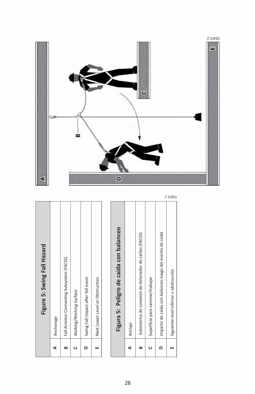
TSSF2.1
Figu
re 5
: Sw
ing
Fall
Haza
rd
A B C D E
Anch
orag
e
Fall
Arr
esto
r C
on
nec
tin
g Su
bsy
stem
(FA
CSS
)
Wal
king
/Wor
king
Sur
face
Swin
g Fa
ll Im
pac
t aft
er f
all e
ven
t
Nex
t Lo
wer
Lev
el o
r O
bst
ructi
on
Figu
ra 5
: Pe
ligro
de
caíd
a co
n ba
lanc
eo
A B C D E
Ancl
aje
Sub
siste
ma
de c
onex
ión
de d
eten
edor
de
caíd
as (F
ACSS
)
Sup
erfi
cie
par
a ca
min
ar/t
rab
ajar
Impa
cto
de c
aída
con
bal
ance
o lu
ego
del e
vent
o de
caí
da
Sigu
ient
e ni
vel i
nfer
ior u
obs
truc
ción
DSSF2.2
28
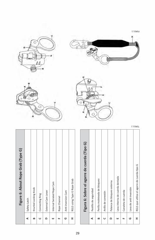
TSRG1.1
FSRG1.1
Figu
re 6
: Abo
ut R
ope
Gra
b (T
ype
G)
Figu
ra 6
: Sob
re e
l aga
rre
de c
uerd
a (T
ipo
G)
A AB BC CF FD DG GE EH H
Safe
ty L
atch
Pesti
llo d
e se
guri
dad
Knur
led
Lock
ing
Knob
Peril
la m
olet
eada
de
bloq
ueo
Co
nn
ecti
ng
Rin
g
Anill
o de
con
exió
n
Rope
Cha
nnel
Cana
leta
de
cuer
da
Exte
rnal
Cam
Lev
er
Pala
nca
de b
loqu
eo e
xter
na
An
ti-i
nve
rsio
n C
am
Leva
de
anti
-in
vers
ión
Inte
rnal
Ser
ated
Rop
e Ca
m
Leva
inte
rna
de c
uerd
a de
ntad
a
RGLS
usin
g Ty
pe G
Rop
e Gr
ab
RG
LS q
ue
uti
liza
el a
garr
e d
e cu
erd
a ti
po
G
29
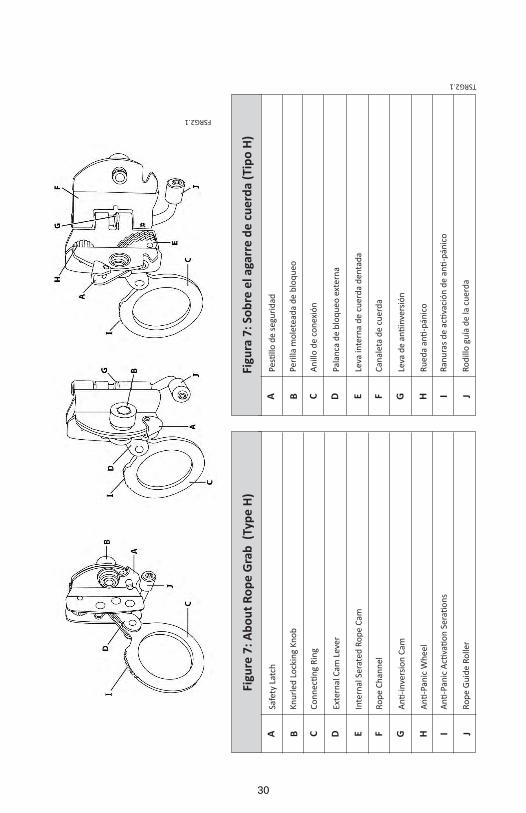
FSRG2.1
Figu
re 7
: Abo
ut R
ope
Gra
b (T
ype
H)
A B C FD G IE H J
Safe
ty L
atch
Knur
led
Lock
ing
Knob
Co
nn
ecti
ng
Rin
g
Rope
Cha
nnel
Exte
rnal
Cam
Lev
er
An
ti-i
nve
rsio
n C
am
An
ti-P
anic
Acti
vati
on
Ser
atio
ns
Inte
rnal
Ser
ated
Rop
e Ca
m
An
ti-P
anic
Wh
eel
Rope
Gui
de R
olle
r
TSRG2.1
Figu
ra 7
: Sob
re e
l aga
rre
de c
uerd
a (T
ipo
H)
A B C FD G IE H J
Pesti
llo d
e se
guri
dad
Peril
la m
olet
eada
de
bloq
ueo
Anill
o de
con
exió
n
Cana
leta
de
cuer
da
Pala
nca
de b
loqu
eo e
xter
na
Leva
de
anti
inve
rsió
n
Ran
ura
s d
e ac
tiva
ció
n d
e an
ti-p
ánic
o
Leva
inte
rna
de c
uerd
a de
ntad
a
Ru
eda
anti
-pán
ico
Rodi
llo g
uía
de la
cue
rda
30
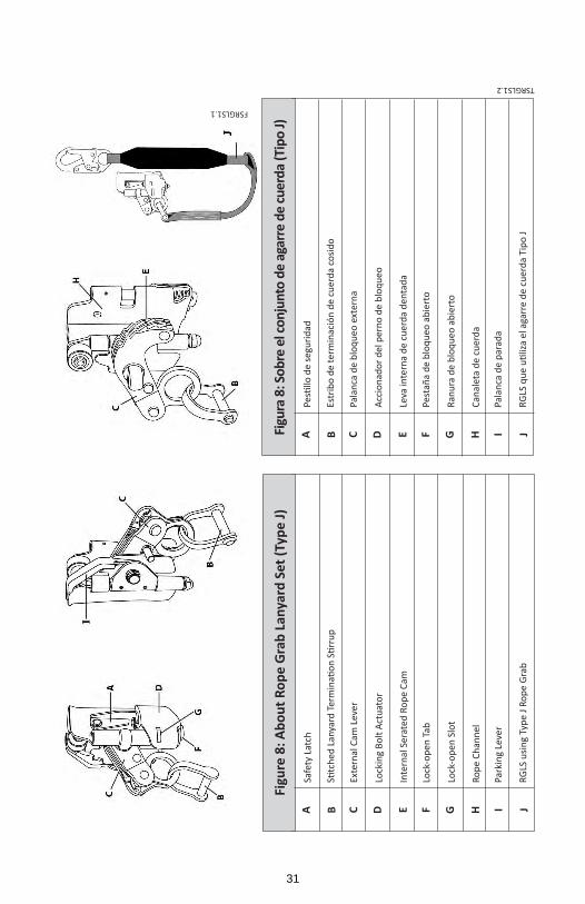
FSRGLS1.1
Figu
re 8
: Abo
ut R
ope
Gra
b La
nyar
d Se
t (Ty
pe J)
A B C FD G IE H J
Safe
ty L
atch
Stitc
hed
Lan
yard
Ter
min
atio
n S
tirr
up
Exte
rnal
Cam
Lev
er
Lock
-ope
n Ta
b
Lock
ing
Bolt
Actu
ator
Lock
-ope
n Sl
ot
Park
ing
Leve
r
Inte
rnal
Ser
ated
Rop
e Ca
m
Rope
Cha
nnel
RGLS
usin
g Ty
pe J
Rope
Gra
b
TSRGLS1.2
Figu
ra 8
: Sob
re e
l con
junt
o de
aga
rre
de cu
erda
(Tip
o J)
A B C FD G IE H J
Pesti
llo d
e se
guri
dad
Estr
ibo
de te
rmin
ació
n de
cue
rda
cosid
o
Pala
nca
de b
loqu
eo e
xter
na
Pest
aña
de b
loqu
eo a
bier
to
Acci
onad
or d
el p
erno
de
bloq
ueo
Ranu
ra d
e bl
oque
o ab
iert
o
Pala
nca
de p
arad
a
Leva
inte
rna
de c
uerd
a de
ntad
a
Cana
leta
de
cuer
da
RG
LS q
ue
uti
liza
el a
garr
e d
e cu
erd
a Ti
po
J
31
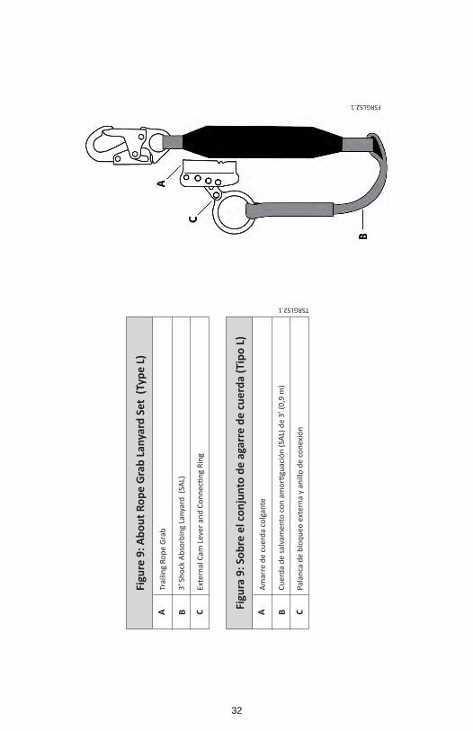
TSRGLS2.1
Figu
re 9
: Abo
ut R
ope
Gra
b La
nyar
d Se
t (T
ype
L)
Figu
ra 9
: Sob
re e
l con
junt
o de
aga
rre
de c
uerd
a (T
ipo
L)
A AB BC C
Trai
ling
Rope
Gra
b
Amar
re d
e cu
erda
col
gant
e
3’ S
hock
Abs
orbi
ng L
anya
rd (
SAL)
Cu
erd
a d
e sa
lvam
ento
co
n a
mo
rtigu
ació
n (
SAL)
de
3’ (
0,9
m)
Exte
rnal
Cam
Lev
er a
nd
Co
nn
ecti
ng
Rin
g
Pala
nca
de b
loqu
eo e
xter
na y
ani
llo d
e co
nexi
ón
FSRGLS2.1
32

TSRGLS3.1
Figu
re 1
0: A
bout
Rop
e G
rab
Lany
ard
Set (
Type
M)
Figu
ra 1
0: S
obre
el c
onju
nto
de a
mar
re d
e cu
erda
(Tip
o M
)
A AB BC C
Man
ual R
ope
Grab
Amar
re d
e cu
erda
man
ual
3’ S
hock
Abs
orbi
ng L
anya
rd (
SAL)
Cu
erd
a d
e sa
lvam
ento
co
n a
mo
rtigu
ació
n (
SAL)
de
3’ (
0,9
m)
Exte
rnal
Cam
Lev
er a
nd
Co
nn
ecti
ng
Rin
g
Pala
nca
de b
loqu
eo e
xter
na y
ani
llo d
e co
nexi
ón
FSRGLS3.1
33
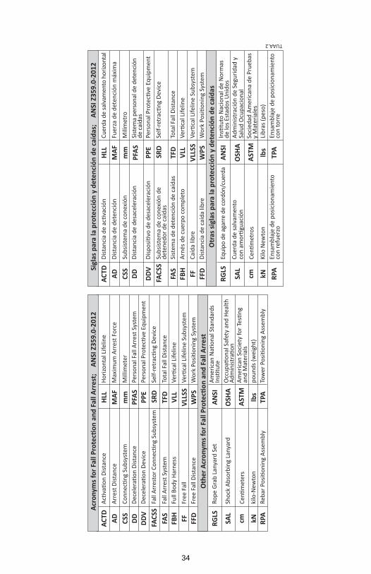
Acr
onym
s for
Fal
l Pro
tecti
on a
nd F
all A
rres
t;
ANSI
Z35
9.0-
2012
Sig
las p
ara
la p
rote
cció
n y
dete
nció
n de
caí
das;
A
NSI
Z35
9.0-
2012
Oth
er A
cron
yms f
or F
all P
rote
ction
and
Fal
l Arr
est
Otr
as si
glas
par
a la
pro
tecc
ión
y de
tenc
ión
de c
aída
s
ACTD
ACTD
RGLS
RGLS
HLL
HLL
ANSI
ANSI
DDV
DDV
RPA
RPA
PPE
PPE
TPA
TPA
ADAD
SAL
SAL
MAF
MAF
OSH
AO
SHA
FACS
SFA
CSS
SRD
SRD
CSS
CSS
cmcm
mm
mm
ASTM
ASTM
FAS
FAS
TFD
TFD
FFFF
VLLS
SVL
LSS
DDDD
kNkN
PFAS
PFAS
lbs
lbs
FBH
FBH
VLL
VLL
FFD
FFD
WPS
WPS
Acti
vati
on
Dis
tan
ceD
ista
nci
a d
e ac
tiva
ció
n
Rope
Gra
b La
nyar
d Se
tEq
uipo
de
agar
re d
e co
rdón
/cue
rda
Horiz
onta
l Life
line
Cuer
da d
e sa
lvam
ento
hor
izont
al
Am
eric
an N
atio
nal
Sta
nd
ard
s In
stitu
teIn
stitu
to N
acio
nal
de
No
rmas
de
los E
stad
os U
nido
s
Dec
eler
atio
n D
evic
eD
isp
osi
tivo
de
des
acel
erac
ión
Reb
ar P
osi
tio
nin
g A
ssem
bly
Ensa
mbl
aje
de p
osic
iona
mie
nto
con
refu
erzo
Pers
on
al P
rote
ctive
Eq
uip
men
tPe
rso
nal
Pro
tecti
ve E
qu
ipm
ent
Tow
er P
osi
tio
nin
g A
ssem
bly
Ensa
mbl
aje
de p
osic
iona
mie
nto
con
torr
e
Arre
st D
istan
ceDi
stan
cia
de d
eten
ción
Shoc
k Ab
sorb
ing
Lany
ard
Cuer
da d
e sa
lvam
ento
co
n a
mo
rtigu
ació
n
Max
imum
Arr
est F
orce
Fuer
za d
e de
tenc
ión
máx
ima
Occ
up
atio
nal
Saf
ety
and
Hea
lth
A
dm
inis
trati
on
Adm
inist
raci
ón d
e Se
gurid
ad y
Sa
lud
Ocu
paci
onal
Fall
Arr
esto
r C
on
nec
tin
g Su
bsy
stem
Subs
istem
a de
con
exió
n de
de
tene
dor d
e ca
ídas
Self
-ret
racti
ng
Dev
ice
Self
-ret
racti
ng
Dev
ice
Co
nn
ecti
ng
Sub
syst
emSu
bsist
ema
de c
onex
ión
Cen
tim
eter
s
Cen
tím
etro
s
Mill
imet
erM
ilím
etro
Am
eric
an S
oci
ety
for
Testi
ng
and
Mat
eria
lsSo
cied
ad A
mer
ican
a de
Pru
ebas
y
Mat
eria
les
Fall
Arre
st S
yste
mSi
stem
a de
det
enci
ón d
e ca
ídas
Tota
l Fal
l Dist
ance
Tota
l Fal
l Dist
ance
Free
Fal
lCa
ída
libre
V
erti
cal L
ifel
ine
Sub
syst
em
Ver
tica
l Lif
elin
e Su
bsy
stem
Dec
eler
atio
n D
ista
nce
Dist
anci
a de
des
acel
erac
ión
kilo
-New
ton
Kilo
New
ton
Pers
onal
Fal
l Arr
est S
yste
mSi
stem
a pe
rson
al d
e de
tenc
ión
de ca
ídas
poun
ds (w
eigh
t)Li
bras
(pes
o)
Full
Body
Har
ness
Arné
s de
cuer
po c
ompl
eto
Ver
tica
l Lif
elin
e
Ver
tica
l Lif
elin
e
Free
Fal
l Dist
ance
Dist
anci
a de
caí
da li
bre
Wo
rk P
osi
tio
nin
g Sy
stem
Wo
rk P
osi
tio
nin
g Sy
stem
TUAA.2
34
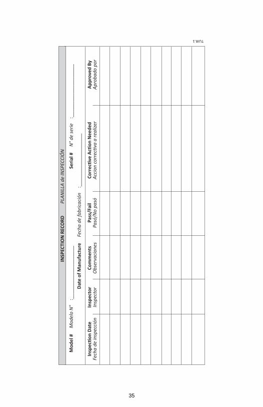
INSP
ECTI
ON
REC
ORD
P
LAN
ILLA
de
INSP
ECCI
ÓN
Mod
el #
M
odel
o N
° :
____
____
____
____
____
Da
te o
f Man
ufac
ture
F
echa
de
fabr
icac
ión
:_
____
____
____
____
___
Se
rial #
N
° de
serie
:_
____
____
____
____
___
Insp
ectio
n Da
teFe
cha
de in
spec
ción
In
spec
tor
Insp
ecto
r Co
mm
ents
O
bser
vaci
ones
Pa
ss/F
ail
Pasó
/No
pasó
Co
rrec
tive
Actio
n N
eede
d
Acci
on c
orre
ctiva
a re
alize
r Ap
prov
ed B
y
Apro
bado
por
TUIR.1
35