fall 2013 volume 27, issue 4 | issn 1069-2010 shot peener · pdf filepatent pending for...
TRANSCRIPT

Fall 2013Volume 27, Issue 4 | ISSN 1069-2010
Shot PeenerThe
Sharing Information and Expanding Global Markets for Shot Peening and Blast Cleaning Industries
Power Puzzle:The Mystery of the
GE Transfer-Gearbox Failures
Wheelabrator Plus: Optimizing Your Peening Process
Air or Wheel
Peening?
How the Shot Stream Force Affects Thin
Components
The New Non-Ferrous Media MagnaValve®
700-24 MagnaValve● Flows Ceramic
Media, Glass Bead and Plastic Media
● CE Compliant
● Closed-Loop Control

Fall 2013 | The Shot Peener 3
Fall 2013 | CONTENT
8Power Puzzle: GE’s transfer-gearbox failures are a mystery but shot peening is recognized as part of the solution
10Wheelabrator Plus: Optimizing your peening process
12Benefits of Nadcap Accreditation and Meetings In this interview from Nadcap’s June 2013 newsletter, Dale Harmon with Cincinnati Thermal Spray shares his thoughts on his company’s relationship with Nadcap.
14Achieving Cost Savings by Reforming Surfaces of Die-Casting DieThrough innovative methods, Sintokogio has observed an increase to the fatigue life of die-casting die. Under typical conditions, die-casting die life can be extended two to three times.
18Air or Wheel Peening?An application-based analysis by Kumar Balan.
24Shot Stream Force Affects Thin ComponentsDr. David Kirk’s article will present how the effects of shot stream force can be quantified and identifying whether or not these effects will significantly affect shot peening parameters.
34New Application and Measurement Fixture for the Toyo Seiko Coverage Checker™
40Rutten Long Life Blast Turbines by Rösler
44Industry News
THE SHOT PEENERSharing Information and Expanding Global Markets for Shot Peening and Blast Cleaning Industries
6Electronics Inc. introduces their new non-ferrous media MagnaValve
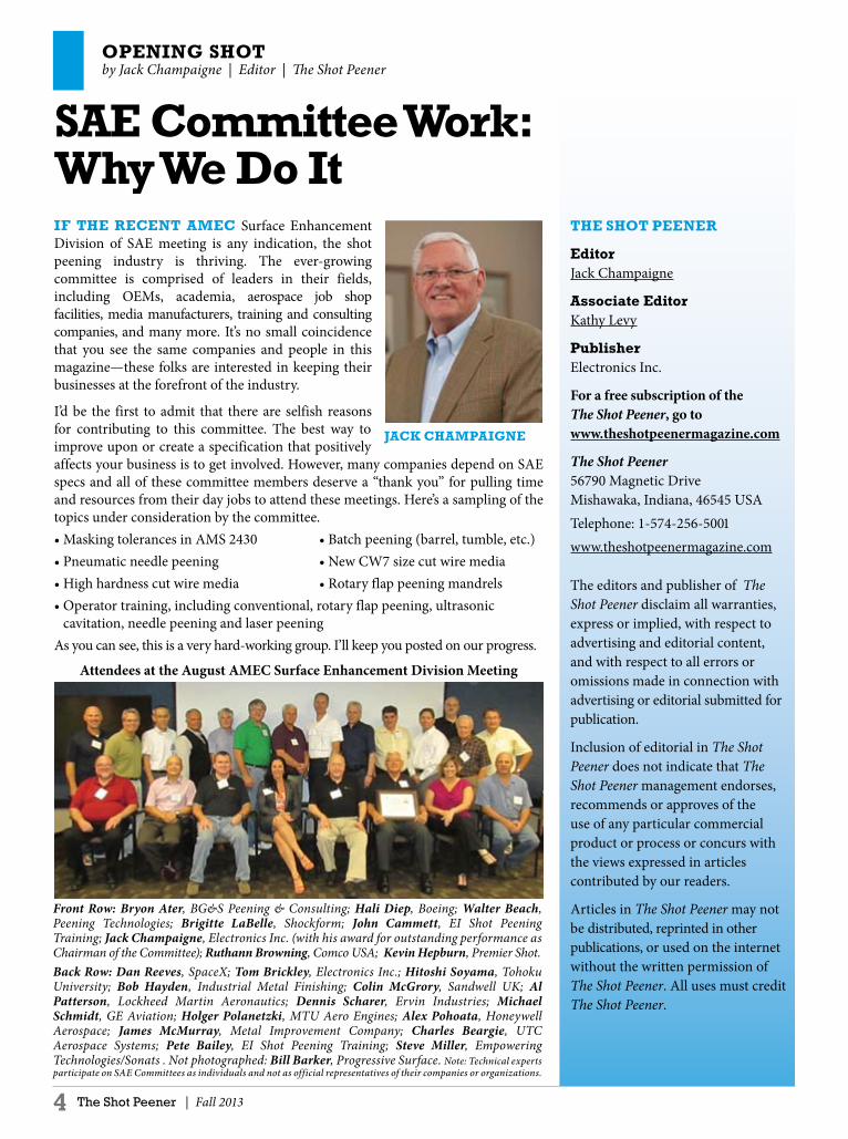
OPENING SHOTby Jack Champaigne | Editor | The Shot Peener
4 The Shot Peener | Fall 2013
THE SHOT PEENER
EditorJack Champaigne
Associate EditorKathy Levy
PublisherElectronics Inc.
For a free subscription of the The Shot Peener, go to www.theshotpeenermagazine.com
The Shot Peener56790 Magnetic Drive Mishawaka, Indiana, 46545 USA Telephone: 1-574-256-5001 www.theshotpeenermagazine.com
The editors and publisher of The Shot Peener disclaim all warranties, express or implied, with respect to advertising and editorial content, and with respect to all errors or omissions made in connection with advertising or editorial submitted for publication.
Inclusion of editorial in The Shot Peener does not indicate that The Shot Peener management endorses, recommends or approves of the use of any particular commercial product or process or concurs with the views expressed in articles contributed by our readers.
Articles in The Shot Peener may not be distributed, reprinted in other publications, or used on the internet without the written permission of The Shot Peener. All uses must credit The Shot Peener.
SAE Committee Work: Why We Do ItIF THE RECENT AMEC Surface Enhancement Division of SAE meeting is any indication, the shot peening industry is thriving. The ever-growing committee is comprised of leaders in their fields, including OEMs, academia, aerospace job shop facilities, media manufacturers, training and consulting companies, and many more. It’s no small coincidence that you see the same companies and people in this magazine—these folks are interested in keeping their businesses at the forefront of the industry.
I’d be the first to admit that there are selfish reasons for contributing to this committee. The best way to improve upon or create a specification that positively affects your business is to get involved. However, many companies depend on SAE specs and all of these committee members deserve a “thank you” for pulling time and resources from their day jobs to attend these meetings. Here’s a sampling of the topics under consideration by the committee.• Masking tolerances in AMS 2430 • Batch peening (barrel, tumble, etc.)• Pneumatic needle peening • New CW7 size cut wire media• High hardness cut wire media • Rotary flap peening mandrels• Operator training, including conventional, rotary flap peening, ultrasonic
cavitation, needle peening and laser peeningAs you can see, this is a very hard-working group. I’ll keep you posted on our progress.
Attendees at the August AMEC Surface Enhancement Division Meeting
JACk CHAMPAIGNE
Front Row: Bryon Ater, BG&S Peening & Consulting; Hali Diep, Boeing; Walter Beach, Peening Technologies; Brigitte LaBelle, Shockform; John Cammett, EI Shot Peening Training; Jack Champaigne, Electronics Inc. (with his award for outstanding performance as Chairman of the Committee); Ruthann Browning, Comco USA; Kevin Hepburn, Premier Shot. Back Row: Dan Reeves, SpaceX; Tom Brickley, Electronics Inc.; Hitoshi Soyama, Tohoku University; Bob Hayden, Industrial Metal Finishing; Colin McGrory, Sandwell UK; Al Patterson, Lockheed Martin Aeronautics; Dennis Scharer, Ervin Industries; Michael Schmidt, GE Aviation; Holger Polanetzki, MTU Aero Engines; Alex Pohoata, Honeywell Aerospace; James McMurray, Metal Improvement Company; Charles Beargie, UTC Aerospace Systems; Pete Bailey, EI Shot Peening Training; Steve Miller, Empowering Technologies/Sonats . Not photographed: Bill Barker, Progressive Surface. Note: Technical experts participate on SAE Committees as individuals and not as official representatives of their companies or organizations.


PRODuCT ANNOuNCEMENTElectronics Inc. | (574) 256-5001 | www.electronics-inc.com
6 The Shot Peener | Fall 2013
Introducing the MagnaValvefor Non-Ferrous MediaThe Model 700-24 for Air Blast Machines THE NEW 700-24 has much in common with the rest of the MagnaValve family: 1) It has a unique design that machine operators love because it’s easy to use and maintain; 2) The 700-24 makes a closed-loop system when used with a standard EI controller and together they provide accurate and repeatable flow rates in shot peening and blast cleaning operations; 3) It uses the same controller as other MagnaValves so its control panel is familiar to machine operators and 4) Like every MagnaValve, the 700-24 provides such a high level of control that it reduces energy and media consumption. The big difference, of course, is in the media. The new valve will flow ceramic media, glass bead, and plastic media on suction- and pressure-type air-blast machines.
How It WorksThe Model 700-24 incorporates an electromagnetically controlled plunger for media flow control. The plunger rests in an orifice. With power applied, an electromagnet raises the plunger to allow media to flow through the valve. The media falls past the plunger and drops onto a blade, bending it according to the media’s flow rate and thereby producing an accurate flow rate signal. When no power is applied to the MagnaValve, the plunger returns to its rest position and stops all media flow. If the power is interrupted for any reason, the plunger returns to the rest position and securely holds the media.
Each Valve Is Custom CalibratedThe Model 700-24 is factory calibrated to the customer’s media. EI maintains a large inventory of many types and sizes of non-ferrous media. In the event that the customer wants a new media flow rate or wants to use a different type or size of media, field calibrations are simple and step-by-step directions are in the valve’s instruction manual.
In Stock and Ready to ShipThe 700-24 MagnaValve has been lab and field tested and is ready to ship. For more information or to order, call EI’s Customer Service staff at (574)256-5001 or 1-800-832-5653 (U.S. and Canada). ●
FEATuRES
Flows Ceramic Media, Glass Bead, and Plastic Media
•±5% Full-Scale Accuracy
•Normally Closed
•Meets SAE AMS 2430 and
2432 Specifications•
24 Vdc Operation•
CE Compliant•
Closed-Loop System Control•
Patented Sensor: US Patent 8,388,047Patent Pending for Magnetic Engine
The Model 700-24 has been the most requested product we’ve ever launched. One customer said they have a backlog of ceramic bead customers that want the valve. Another will use it to “blend” their mixes of glass bead. If you are peening to AMS 2432 or AMS S-13165 and using glass bead or ceramic bead, there is a requirement to measure/record flow rate. Now it’s possible with the Model 700 MagnaValve.
— Jack ChampaigneElectronics Inc.

Fall 2013 | The Shot Peener 7
Prepared for performance
High precision peening solutions
www.wheelabratorgroup.comNorican Group is the parent company of DISA and Wheelabrator.
Whether you are peening large areas with centrifugal wheels or targeting specifi c areas with CNC automated airblast nozzles,
Wheelabrator will deliver the right solution to meet your needs.
Contact us to fi nd out how.
US: 800-544-4144 • Canada: 800-845-8508 • [email protected]
New_ad_8.25x11_Fall_2009_V2.indd 1 18.09.2009 09:29:03

8 The Shot Peener | Fall 2013
SHOT PEENING AND SAFETyGuy Norris | Aviation Week & Space Technology
Power Puzzle
COuLD THERE BE any connection between the end of the summer vacation period in Italy last year and the unexpected diversion of a Korean Air Boeing 777-300ER on July 2 to a remote airport in Russia? This might sound like the unlikely plot line of a modern-day detective story, but it is one line of inquiry General Electric is pursuing as it investigates a puzzling string of transfer-gearbox failures this year on its otherwise reliable GE90-115B engine. The latest incident, which occurred as the Korean Air aircraft was flying from Chicago to Incheon, followed virtually identical failures on other 777s earlier this year. Made by GE’s Italian-based supplier Avio, the affected part is the transfer gearbox, which transmits energy from the engine core to drive the accessory gearbox. When the problems first occurred, GE and Avio originally suspected a material “anomaly” as the source of the issue, which was manifested in cracking and separation in the radial gear. Detailed examination of the gears involved led the manufacturers to believe the issue was isolated to a specific batch of gearboxes made between September 2012 and March 2013. However, the engine in the Korean Air incident involved a brand-new 777 and GE90s that incorporated gears assembled as recently as June, catching GE offguard and forcing it to reconsider other causes. When the material anomaly was originally suspected earlier this year, GE employed an enhanced Eddy Current Inspection (ECI) process to check for possible gear separationwithin the transfer gearbox. However, although the ECI did reveal two more cases of cracking, it did not pinpoint material issues as the cause. The manufacturers therefore switched the investigation to the heat transfer process used in the making of the gearbox housing as the possible cause of surface stress on the gear that, in turn, led to radial cracking and the separation. The puzzle remains, though, as to what changed in the process that until last September had produced problem-free gearbox assemblies. “It’s been mysterious,” says GE, which adds that it has looked into any changes that may have been
made in the Avio equipment. The timing of the first faulty gear assembly also coincides with the period when Italian industry traditionally ramps up after the summer break. To counter the separation issue, since mid-June Avio has been treating all transfer-gearbox housings with a cold working process called shot peening, which entails impactingthe surface with a high-velocity shot that plastically deforms the metal, producing a surface more resistant to fatigue. The Korean Air aircraft involved in the July 2 diversion is the only one of the airline’s fleet of 15 777-300ERs that was fitted with transfer gearboxes from the suspect population of 132 engines. Both gearboxes were replaced and the aircraft has returned to service, GE notes. The Korean Air inflight shutdown triggered the FAA to issue an emergency airworthiness directive (AD) on July 12 mandating “de-twinning” of 20 more 777-300ERs by replacing the transfer-gearbox assembly with an earlier model or with a modified version. The action was essentially a repeat of the AD issued in May in the wake of an inflight shutdown in February on an Aeroflot 777-300ER en route to Moscow from Bangkok, and a similar event on May 9, when an Air China flight from Beijing to Paris diverted to Stockholm after the left engine had to be shut down in flight. GE says that as of July 18, the suspect fleet of engines still flying had been reduced to 29. “With the ones completed, either the entire gearbox was replaced or a couple of the suspect gears in the transfer gearbox were replaced with ones that were shot-peened,” says the engine maker. The extent of the refurbishment task remains large, as there are now many other engines to replenish on the production line and in maintenance and repair shops. GE is also expected to issue a service bulletin shortly, requiring all suspect transfer gearboxes to be removed from service by late September. The Korea Aviation and Railway Accident Investigation Board delegated the investigation of the July 2 inflight shutdown to the U.S. NTSB, which is working with GE and the FAA to determine the root cause. GE says the “final probable cause” for the July 2 event will be determined by the NTSB. ●
Used with permission of Aviation Week & Space Technology Copyright© 2013. All rights reserved.
GE Probes mystery of 777 engine transfer-gearbox failures after third inflight shut down


10 The Shot Peener | Fall 2013
From automotive gears and engine components to wing spars and landing gear, a Wheelabrator Automated Peening system can be configured in the EMP process to comply with the necessary requirements. Typical benefits from EMP include:• Improved productivity, throughput and cycle
time reductions• Reduced maintenance downtime• Improved reliability• Specification compliance• Expanded capacity to support product offering• Reduced abrasive consumption• EHS and environmental complianceWheelabrator Group’s thousands of customer
equipment solutions, comprehensive process knowledge and dedicated technical teams provide the confidence to tackle the most challenging equipment upgrade opportunities. Whether new equipment to meet your growth requirements or productivity improvements to an existing asset, contact Wheelabrator Group to optimize your peening and cleaning operations at [email protected]. ●
INNOVATIONS IN AFTERMARkET by Marty Magill | Senior Vice President | Wheelabrator Plus North America
Wheelabrator Plus – Optimizing your Peening Process
WITH OVER 50,000 MACHINES supplied to 15,000 active customers worldwide, Wheelabrator Plus maintains the largest installed base in the industry. Although most well known for shotblast applications, Peening has been an integral part of the Wheelabrator offering since the earliest days. “Wheelapeening” was introduced in the 1940’s for automotive applications and Wheelabrator became the industry leader in peening of aircraft landing gear in the 1960’s. The legacy continues today with peening leadership in diverse industries including automotive, aerospace, defense and medical applications. In 2005, the Wheelabrator Group solidified their formidable aftermarket services with the formation of Wheelabrator Plus. This dedicated business unit is focused on the critical needs of equipment owners to continually reduce cost and increase productivity. Wheelabrator Plus’ range of services is supported by regionally located sales and service teams offering the latest OEM technology. The most unique offering is their pioneering Equipment Modernization Program or EMP. “We work with customers to understand performance objectives and optimize our equipment to meet customized surface preparation requirements as they change over time,” said Martin Magill, Sr. Vice President Wheelabrator Plus N.A. “Our job is to make sure that equipment continues to reliably deliver effective performance despite changes in product or process from the original commissioning.” The Equipment Modernization Program optimizes productivity and maintains specification compliance of an existing asset through technology upgrades. The EMP process is applied to peening applications to meet evolving original equipment manufacturers speci-fications for peening reliability and compliance as well as accommodating changes in part configuration, specifications or media. In many cases this means modernizing the existing centrifugal blast wheels and nozzle/lance style technology. Project process scope may include automated monitoring as well as reporting of critical process control parameters such as media flow rate and velocity, media size and shape control, real-time process display and required audit compliance.
Marty Magill Senior Vice President
Wheelabrator Plus North America
Wheelabrator Plus will help you upgrade your existing centrifugal blast wheels or nozzle/lance-style
technology for peening applications.

Fall 2013 | The Shot Peener 11
Innovative Peening Systems IPS....
Fanuc CNC Controlled
S SeriesFive Axis CNC
Computer Controlled Shot Peening Machine
Part Capacity 24” dia x 36” high
L SeriesSix Axis CNC Computer Controlled Shot Peening Machine
Part Capacity 48” dia x 48” high
Rotary Lance
CNC is no longer exclusive to the Fortune 500Our affordable CNC machines allows every shot peener to eliminate manual nozzle setups. CNC offers exceptional part processing speeds, accuracy of peening and consistent quality of parts.
Innovative Peening Systems 2825 Simpson Circle Norcross, GA 30071
770-246-9883

NADCAP COMMuNICATIONS
12 The Shot Peener | Fall 2013
Benefits of Nadcap Accreditation and Meetings
In this interview from Nadcap’s June 2013 newsletter, Dale Harmon with Cincinnati Thermal Spray shares his thoughts on his company’s relationship with Nadcap
What is your current Nadcap status? We have merit for chemical processing and coatings. Three of our four sites are Nadcap accredited.
Why did your company decide to attain Nadcap accreditation in the first place? It was a customer requirement – simple as that!
What challenges have you faced in gaining and keeping Nadcap accreditation? Well, I was in Engineering when we first got involved in Nadcap. Although I wasn’t in a leadership role, I wrote about a third of our procedures that we needed in order to get accredited. That was a big challenge, and it’s an ongoing one, because we have to make sure all our systems and procedures are kept up-to-date; it’s not a one-off activity. It’s tough and time-consuming but I have to tell you, going to the Nadcap meetings is a big help. One of the main benefits of attending the meetings, as far as I’m concerned, is that I get to hear what’s going to change in the checklists ahead of time. I bring that information back to my company so we can make any adjustments as necessary to our procedures or practices in good time before our next audit. More than that, by being at the meetings, I actually get a voice in any proposed changes, which is invaluable, as they have a real impact on my company.
What benefits have you seen from being Nadcap accredited? Accreditation initially allowed us to maintain our aerospace customer base and, later, to expand in the industry. Our third facility, which did no aerospace work initially, achieved Nadcap accreditation to improve processes and then experienced business expansion to include aerospace customers. Being involved in Nadcap also helps because I know where the information is, and whom to ask if I have questions. For example, if we are investigating bringing a new process on board, one of the first things I do is download the Nadcap checklist and use it to ensure our process controls are in place. Even if the new work is not for a Nadcap subscriber, or even for an aerospace company, the discipline required to pass a Nadcap audit is a best practice I like to follow. The work has been done – and by industry experts who have collectively more years’ experience in the field than I will ever have – so
why not use their insights to improve quality at my company? That’s what Nadcap is about, after all. I briefly mentioned the Nadcap meetings already but I want to highlight again why they are so good and such a benefit of being involved in Nadcap. As well as keeping abreast of new developments and getting to input into the audit checklists, which I already talked about, the meetings are a great way to network with customers and other companies in your field, which is incredibly useful. The people who make the decisions on new approvals for my company are at the meeting – that’s a very powerful thing. Also, I think the fact that they see that my company supports Nadcap to the extent that I now attend every meeting speaks volumes to them regarding our commitment to quality and supporting global industry improvement.
Why did you want to get involved with the Nadcap Supplier Support Committee? Back in 2004, the Coatings Task Group Supplier Lead, who’d been involved since the very beginning, retired and I was selected by the Task Group as his replacement. At that time, Arne Logan of The Boeing Company was Nadcap Management Council Chairperson and a really strong supporter of the SSC. Although I am involved with SSC activities, my priority is the Task Group work. That’s why my company pays for me to attend the meetings. Now, I’m actually Secretary of the Coatings Task Group.
What SSC achievement are you most proud of? We started the Supplier Help Desk, or Supplier Support Center, about three years ago and I’m now the leading that effort. The purpose is to help suppliers at the Nadcap meetings by providing them with information about the meeting as a whole and the SSC activities that take place there that could be of benefit to them. We are inundated with queries at the meetings. The first two days, when lots of people are arriving, is when we are most busy. New attendees especially don’t know what meeting to attend, which Task Group they should go to, where everything is… it can definitely be a bit overwhelming for first-timers and I’m pleased to be able to help. There are PRI staff there to help too, of course, but sometimes it’s nice to interact with your peers. ●Copyright @ 2013 Performance Review Institute. All Rights Reserved.
12 The Shot Peener | Fall 2013

Fall 2013 | The Shot Peener 131Spring 2006 The Shot Peener
Premier ShotPremier ShotA cut above
The advantages of Premier Cut Wire ShotThe advantages of Premier Cut Wire Shot● Highest Durability - Due to its wrought internal structure with almost no internal defects (cracks, porosity, shrinkage, etc.) the durability of Premier Cut Wire Shot can be many
times that of other commonly used peening media.
● Improved Consistency - Highest consistency from particle to particle in size, shape, hardness and density compared to commonly used metallic media.
● Highest Resistance to Fracture - Cut Wire Shot media tends to wear down and become smaller in size rather than fracture into sharp-edge broken particles which may cause
damage to the surface of the part being peened.
● Lower Dust Generation - Highest durability equals lowest dust levels. ● Lower Surface Contamination - Cut Wire Shot doesn’t have an Iron Oxide coating or leave Iron Oxide residue - parts are cleaner and brighter.
● Improved Part Life - Parts exhibit higher and more consistent life than those peened with equivalent size and hardness cast steel shot.
● Substantial Cost Savings - The increase in useful life of Premier Cut Wire Shot results in savings in media consumption and reclamation, dust removal and containment, surface contamination and equipment maintenance.
(330)405-0583www.premiershot.com
Premier Shot proudly manufactures shot to meet today's high quality shot peening standards and is used in automotive, medical
and aerospace applications worldwide.Premier Shot Company: 1666 Enterprise Parkway, Twinsburg, Ohio 44087
Special ConditioningNormal ConditioningAs-cut

Fig.1 Surface property before and after D-CHECK
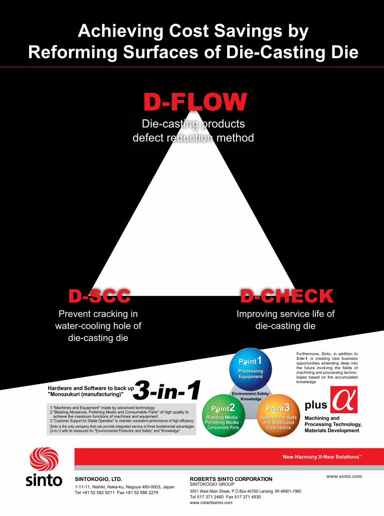
D-SCC: Prevent cracking in water-cooling hole of die-casting dieWater-cooling holes are drilled increasingly closer to the cavity to obtain quicker cooling, but die-cast users report defects due to water that seeps through cracks from the water cooling hole. (Fig.2) The D-SCC uses shot peening to protect water-cooling holes from stress corrosion cracking (SCC). With D-SCC, the peening is done specifically in the water-cooling hole of the die-casting die and can be performed on holes with a diameter as small as 4 mm and a depth of up to 200 mm by special nozzle. (Fig.3) In actual mass production lines, fatigue life of die expanded three to four times compared with non-peened die. The benefits of heat check prevention and stress corrosion cracking reduction are achieved through the increase of residual stress as a result of the shot peening. The surface residual stress is increased from -250 MPa for untreated to -1500MPa for surfaces that have been treated by peening.
Fig.2 The stress corrosion cracking that appeared in the water-cooling hole
14 The Shot Peener | Fall 2013
PROCESS INNOVATIONSSintokogio, Ltd. | www.sinto.co.jp
Achieving Cost Savings by Reforming Surfaces
of Die-Casting DieThrough these innovative methods, Sintokogio has observed an increase to the fatigue life of die casting die.
Under typical conditions, die-casting die life can be extended two to three times.
READERS OF THE SHOT PEENER are well aware of the many benefits of shot peening in increasing surface residual stress. In this article we will show how increased surface residual stress can lead to improvements in production and in fatigue life in die-casting die. We will discuss two methods for improving die-casting die life through shot peening called D-CHECK and D-SCC. We will also present one method for improving the products quality called D-FLOW. By using these methods, die-casters can reduce the number of defects and increase the fatigue life of the die-casting die. These improvements directly translate to cost and energy savings for manufacturers.
Die CastingReaders will be familiar with die-casting, but we include a very short explanation of the process for clarity. Die casting is a metal casting process that is characterized by forcing molten metal under high pressure into a mold cavity. The mold cavity is created using two hardened tool steel dies, which have been machined into shape and work similarly to an injection mold during the process. Die castings are known for high production efficiency and high strength.
D-CHECk: Improving service life of die-casting dieThe primary factor that effects die-casting die service life is heat checking. (Heat checking is the fine cracks on the surface of a die which produce corresponding raised veins on die castings. Heat checking is caused by repeated heating of the die surface by injected molten alloys.) The D-CHECK process uses shot peening to prevent heat checking and extend the life of die-casting die by two to three times. The obvious benefit of extending service life is productivity improvements and cost reductions. Cost reductions are achieved by maintenance reduction and by reducing cost associated with creating new die. Surface property of after D-CHECK is shown in Fig.1
Before D-CHECK After D-CHECK
Fall 2013 | The Shot Peener 15
www.sinto.com
Achieving Cost Savings byReforming Surfaces of Die-Casting Die
D-FLOWDie-casting products
defect reduction method
D-SCCPrevent cracking in
water-cooling hole ofdie-casting die
D-CHECKImproving service life of
die-casting die
1."Machines and Equipment" made by advanced technology2."Blasting Abrasives, Polishing Media and Consumable Parts" of high quality to achieve the maximum functions of machines and equipment3."Customer Support for Stable Operation" to maintain consistent performance of high efficiency
Sinto is the only company that can provide integrated service of three fundamental advantages (3-in-1) with its measures for "Environmental Protection and Safety" and "Knowledge".
Hardware and Software to back up "Monozukuri (manufacturing)"
ProcessingEquipmentProcessingEquipment
Point1Point1
Blasting Media ・Polishing Media ・
Consumable Parts
Blasting Media ・Polishing Media ・
Consumable Parts
Point2Point2Support for Safe
and StabilizedOperations
Support for Safeand Stabilized
Operations
Point3Point3
Environment-Safety・Knowledge
Furthermore, Sinto, in addition to 3-in-1, is creating new business opportunities extending deep into the future involving the fields of machining and processing techno-logies based on the accumulated knowledge.
plusMachining and Processing Technology,Materials Development
3-in-1
1-11-11, Nishiki, Naka-ku, Nagoya 460-0003, JapanTel +81 52 582 9211 Fax +81 52 586 2279
SINTOKOGIO, LTD. SINTOKOGIO GROUP
3001 West Main Street, P.O.Box 40760 Lansing, MI 48901-7960Tel 517 371 2460 Fax 517 371 4930www.robertssinto.com
ROBERTS SINTO CORPORATION

PROCESS INNOVATIONS Continued
16 The Shot Peener | Fall 2013
Fig.3 Nozzle for internal surface
D-FLOW: Die-casting products defect reduction methodThe D-FLOW process greatly reduces casting defects by modifying the die casting mold surfaces. This surface processing method contributes to improved quality, increased energy savings, reduced carbon footprint, and increased cost savings by reducing products defect. After implementing the D-FLOW process, we saw eddy flows caused by dimpling return the colder surface molten material to the inside and help to maintain the molten material temperature by providing the heat of the internal material to the surface. The dimpling also controls reduction in molten material temperature by decreasing the contact surface. Though results depend on conditions, we observed a 50% reduction to the defect occurrence rate. Reductions were seen in peeling, flow lines, blowholes, and soldering. (Fig.4)
Fig.4 The soldering which occurred on the product surface.
Before D-FLOW After D-FLOW


Air or Wheel Peening?An Application-Based Analysis
MANy ENGINEERING PROBLEMS have more than one solution. Application Engineers, however, are asked to find the one optimal solution given a list of variables and possibilities. In our industry, we are often called upon to recommend and validate our choice for the best media propulsion system—airblast or wheelblast—for the customer’s application. Very often, either type will work for their application, and each has its own inherent advantages and shortcomings. While I’ve had the luxury of being able to offer both airblast and wheelblast solutions since the company I represented manufactured both systems, I still needed to recommend one or the other to my customers. In this article, I’ll review the basics of each option, categorize the applications, and define and validate the criteria that leads to the best solution.
THE BASICSWheelblast machines use a centrifugal blast wheel to propel media and airblast machines use compressed air. All other factors being equal, the productivity of the blast operation is directly proportional to the amount of abrasive propelled onto the part. In quantifiable terms, an airblast nozzle (3/8" or 9.5 mm diameter at 60 PSI or 4.1 bar) propelling metallic abrasive typically discharges only 10% of the blast media that can be propelled by a centrifugal blast wheel (15" or 381 mm diameter wheel powered by a 20 HP or 15 KW motor). To get an even clearer perspective on operating efficiency, a single centrifugal wheel provides the same cleaning efficiency as eight (8) ½" or 12.7 mm diameter blast nozzles. Centrifugal blast wheels are either direct driven or belt driven through a bearing system. The resulting line speed of the associated blast machine is directly proportional to the total connected wheel horsepower. Applications in wheelblast are wide and varied, and given that the first blast wheel was patented over a hundred years ago, wheelblast machines are prevalent in most automated cleaning applications. The blast nozzle in an airblast system is powered by compressed air. The peening intensity is directly proportional to the air pressure level. There are two types of airblast systems—suction and pressure.
SHOT PEENING EquIPMENTby Kumar Balan | B. Eng., MBA
18 The Shot Peener | Fall 2013
Suction-style propulsion systems are used for relatively lower intensity peening requirements with small ferrous and non-ferrous abrasives of all sizes. Pressurization of the blast media takes place inside the blast gun, eliminating the need for a separate blast tank. A suction gun is identified by two hoses, a red hose for compressed air and a black hose for the abrasive. A venturi or airjet inside the suction gun creates the suction and mixes compressed air and media prior to discharge from the gun. Direct pressure systems are more commonly used than suction systems. As a rule of thumb, pressure blast systems are about two to three times as efficient as suction systems. Pressurization of the blast media takes place in a separate pressure vessel called the blast tank or blast pot. A single hose, carrying pressurized abrasive, is connected to the blast nozzle. Nozzles can be straight bore or venturi style, as suited to the application. Suction blast uses less compressed air than direct pressure. A 3/8" or 9.5 mm suction nozzle with a 3/16" or 4.5 mm diameter air jet will consume 40 CFM or 68 cubic meter per hour at 80 PSI or 5.4 Bar. In comparison, a 3/8" direct pressure nozzle at 80 PSI will consume 175 CFM or 300 cubic meter per hour of compressed air.
CRITERIA FOR CHOOSING BETWEEN WHEELBLAST OR AIRBLAST EquIPMENTCriteria for Choosing Wheelblast Equipment• Large production volumes with large runs of physically
similar components• Component needs to be completely treated with abrasive
and there is no need for masking• Treatment area is large• User has several wheelblast machines and has an acceptable
process for similar components• Process specification calls for high-intensity values on
large surface areas with large-size abrasive (common in automotive and railway applications)
Typical contenders for wheelblast peening are auto transmission components such as gears and shafts, connecting rods, coil and leaf springs and axle beams. In the

Winter 2013 | The Shot Peener 19
The FLAPSPEED® Controllerfor Rotary Flapper Peening
Repeatability, Quality, Productivity.
BECAUSE SPEED IS NOTHING WITHOUT CONTROL
www.shockform.com(450) 430-8000

SHOT PEENING EquIPMENT Continued
20 The Shot Peener | Fall 2013
aerospace industry, landing gear, aircraft wheels and brakes are peened in a wheelblast machine.
Criteria for Choosing Airblast Equipment• Only specific areas of the component need to be peened,
with the other areas requiring protection from the abrasive • Component is to be treated with non-ferrous abrasive• Areas such as main bore, slots and other intricacies are to
be peened• Application requires significant manipulation of the blast
stream in order to provide proper coverage• Availability of compressed airTo recap, the same automotive and aerospace components that were good candidates for wheelblast should be peened in an airblast machine when only specific areas need to be peened and/or if the process requires non-ferrous media.
Wheelblast versus Airblast for Automotive TransmissionGears and shafts can be peened in either machine type. In both cases, the machines are rotary indexing tables with multiple satellite fixtures on top that expose individual stacks of gears or a single shaft to the blast wheel, multiple blast wheels or reciprocating nozzles. Wheelblast machines are used in high production environments and when the gear tooth geometry permits unimpeded access to the abrasive. The root section of the gear is the most critical area to be shot peened since this is where cracks tend to originate. Therefore, blast wheel location and part fixturing are important design parameters in this machine type. Using a more sophisticated arrangement, some wheelblast machine types also offer vertical wheel movement/oscillation to ensure proper coverage is achieved when peening a tall stack of gears or a shaft. Arguments can be made about the efficacy of air-type machines over wheel, and there are clear lines of demarcation. Though production specifics will depend on several other factors, the production rate of airblast peening machines for gears is lower than its wheelblast counterpart. However, airblast provides precision or targeted blasting, resulting in lower abrasive consumption and breakdown. The direct tangible benefit is a more efficient use of available power and the elimination of unnecessary wear on machine components.
Wheelblast versus Airblast for Landing GearWhen the entire landing gear needs to be peened, as is typical in new gear manufacturing, a spinner hanger wheelblast machine provides efficient coverage. The blast chamber is fitted with multiple wheels in strategic locations to access all areas of the landing gear. When the specification calls for spot peening, typically in MRO and refurbishing operations, the applications are best addressed with an airblast machine. Also, an airblast lance is the only means of peening the ID of the gear, whether in specific areas or along the entire length.
PROCESS PARAMETERS FOR BOTH WHEEL AND AIR MACHINES• Media flow rate monitored with a MagnaValve, or comparable
valve, and validated through drop tests. • Media classification (size and shape) using a vibratory
classifier to maintain a consistent size and spiral separator to separate rounds from non-rounds. Due to high flow rates in a wheelblast machine, it is acceptable to sample the flow by diverting a percentage (usually 20%) of the total flow through a vibratory classifier on a continuous basis.
• Exposure time monitoring by controlling the speed of work handling arrangement such as rotary table, inline conveyor or speed of nozzle movement in an airblast machine.
• Consistent pressure delivery in airblast machines. The air pressure in an airblast machine determines the peening intensity so it is critical to monitor and maintain consistent pressure delivery in order to get consistent peening intensity results.
• The wheel speed, if all other parameters are stable, determines the intensity in a wheelblast machine. Blast wheels in a wheelblast peening machine are fitted with a variable frequency drive in order to monitor and alter the wheel speed as required.
A NOTE ON HyBRID BLAST MACHINESA hybrid blast machine capitalizes on the advantage of the wheelblast propulsion technique to peen the majority of the part surface and relies on blast nozzles to complete the process by targeting specific areas insufficiently covered by the blast wheels —all in a common enclosure and sharing reclaim and control system components. The decision between airblast and wheelblast takes a different dimension with hybrid machines. These machines offer distinct advantages over dedicated air or wheel machines:• Cycle time savings due to reduced handling• Commonality of fixtures• Labor savings (operator required for one machine only)• Machine certification simplified because only one machine
needs to be certified
Hybrid machines are ideally suited to ‘complete’ the process in a high-production environment with the majority of the area already processed by a single or multiple blast wheels.(For more information on hybrids, download “Hybrid Cleaning/Peening Machines” by Mr. Balan, The Shot Peener, Fall 2007 from the Library at www.shotpeener.com.)
CONCLuSIONAs we have read, there are multiple equipment solutions for applications such as transmission components and landing gear. Application engineers must assess each individual process and the site constraints, keeping in view that the final goal remains unaltered—an accurate and repeatable peening operation. ●

Fall 2013 | The Shot Peener 21
NATIONAL PEENINGSINTOKOGIO GROUPTel 800-325-7336www.nationalpeening.com
Brand Design Guidelinesブランドデザインガイドライン
New Harmony >> New Solutions
www.sinto.com
TM
Brand Design Guidelinesブランドデザインガイドライン
Peening Solutions ForAEROSPACE AUTOMOTIVE MEDICAL
POWER GENERATION
Now with Contract Peening Resources!
Visit us at Shot Peening Workshop
October 15-17, 2013Scottsdale, Arizona
ONE GLOBAL SINTO

ACADEMIC STuDyby Prof. Dr. David Kirk | Coventry University, U.K.
22 The Shot Peener | Fall 2013
INTRODUCTIONThe force exerted by a shot stream must always generate some degree of component bending. This bending may be so small as to be insignificant—as is the case with ‘thick’ components. With ‘thin’ components, however, component bending always induces an element of stress peening. The degree of bending depends on three factors:
Magnitude of applied force, F, Thickness of component, t, and Distance between supports, L.
Fig.1 illustrates the three controlling factors applied to, for example, a machined computer case. Sample calculations indicate that: for a force of 10 N applied centrally to an aluminum case 1mm thick, 200 mm wide by 300 mm long (.04" x 8" x 12"), the deflection would be 5 mm (.2"). At 0.78 mm (.03") thick the deflection would be 10 mm (.4").
Fig.1 Schematic representation of factors affecting shot stream bending of a component.
It was shown, in the previous article in this series, that the magnitude of the shot stream force can be both predicted and measured. The force that an air-blast shot stream applies (to reasonably-flat surfaces) is in the region of tens of Newtons. Wheel-blast machines can impose hundreds of Newtons of force. Force is generated by a combination of the air stream and the high-velocity shot particles. Very large forces can be exerted when water is used, either on its own or as the accelerating fluid for shot particles. The thickness of a component determines its rigidity (resistance to bending) and the distance between supports determines the amount of ‘bending moment’ that a given force generates. Component bending generates a stress distribution in the component with maximum stresses being at the surface.
For the previous example, a surface stress of ±23 MPa can be predicted at 45% of the yield strength of pure aluminum. This article is concerned with showing (a) how the effects of shot stream force can be quantified and (b) identifying whether or not these effects will significantly affect shot peening parameters—such as peening intensity, coverage and residual stress profile. Simple component shapes are used to minimize the mathematical complexities involved. As shot peening evolves there is an increasing interaction with other engineering disciplines. Several basic mechanical engineering principles are invoked in this article.
INDUCED BENDINGRigidityThe amount of bending depends upon the component’s rigidity. A simple demonstration is to press one finger on the center of Almen strips whilst they are mounted on an Almen gage. N strips will show a significant dial reading with even a gentle pressure. C strips, on the other hand, will not show a significant deflection - even with a high finger pressure.
For rectangular components the rigidity, I, is given by: I = w*t3/12 (1) where w is strip width and t is strip thickness.
Equation (1) shows that the rigidity is proportional to the cube of the thickness. For N, A and C strips, w is constant but the strip thickness t, varies. The ratios of thickness cubed are: 1 to 4.5 to 28 for N, A and C strips respectively. Hence, C strips are 28 times as rigid as are N strips and A strips are 4.5 times as rigid as are N strips.
DeflectionDeflection, d, of a rectangular beam of length, L, with a centrally-applied load, F, is given by the ‘textbook’ equation:
d = F*L3/(48*E*I) (2)
where E is the elastic modulus of the component material.
Substituting the value for I given in equation (1) gives that:
d = F*L3/(4*E*w*t3) (3) Equation (3) gives us a quantitative ‘feel’ for the magnitude of deflection. Doubling the force doubles the deflection whereas doubling either the modulus or the width halves the deflection.
Shot Stream ForceAffects Thin Components
Continued on page 26

Fall 2013 | The Shot Peener 23
Materials Testing Services
www.TECstress.com865.966.5856
Materials Testing Division • 10737 Lexington Drive • Knoxville, TN 37932 USA
When you use TEC’s accredited laboratory, you can be sure
that you will receive superior analysis and technical support.
We meet today’s strictest quality standards by maintaining A2LA
accreditation and ISO-9001 registration. Scheduled turnaround
of analysis results is always rapid, however, we can also adapt to
meet critical deadlines when you need immediate results.
Residual StressBy managing residual stresses during the manufacturing process, you and your customers can reduce failures caused by phenomenon such as fatigue and stress corrosion cracking.
Retained AusteniteWe calculate retained austenite using the four-peak method of measuring two austenite and two martensite peaks - recommended by both ASTM and SAE for obtaining accurate results.
In-House or Field ServicesUtilizing the portability of our own X-Ray Diffraction System, TEC lab personnel can perform measurements on parts ranging from a fraction of an inch to several hundred feet with guaranteed rapid and precise results.
At TEC, our customers are our partners. Our expert staff is
dedicated to helping you meet your own quality control demands.
Contact us today for more information.
ISOREGISTERED
9001
24 The Shot Peener | Fall 2013
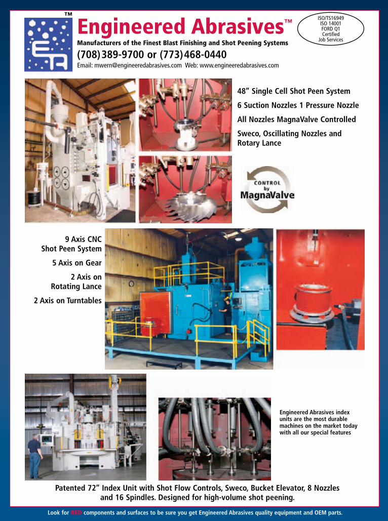
Engineered Abrasives™
Manufacturers of the Finest Blast Finishing and Shot Peening Systems
(708)389-9700 or (773)468-0440Email: [email protected] Web: www.engineeredabrasives.com
ISO/TS16949ISO 14001FORD Q1Certified
Job Services
Engineered Abrasives index units are the most durable machines on the market today with all our special features
48’’ Single Cell Shot Peen System
6 Suction Nozzles 1 Pressure Nozzle
All Nozzles MagnaValve Controlled
Sweco, Oscillating Nozzles and Rotary Lance
9 Axis CNC Shot Peen System
5 Axis on Gear
2 Axis on Rotating Lance
2 Axis on Turntables
Patented 72’’ Index Unit with Shot Flow Controls, Sweco, Bucket Elevator, 8 Nozzles and 16 Spindles. Designed for high-volume shot peening.
™
Look for RED components and surfaces to be sure you get Engineered Abrasives quality equipment and OEM parts.

Fall 2013 | The Shot Peener 25
The largest 5-Axis CNC 96" Shot Peening Index Table made. Two-media capacity with MagnaValves for large rings and pinions up to 33" O.D. Designed for higher volumes. (GE 31-i Series Controller)
Large 84" Index Unit for
high volume
12 Pressure Nozzles with MagnaValves
Automatic load/unload1,000 gears per hour
Single Cell Unit, 5 Pressure Nozzles Large 84" Index Unit, 12 Pressure Nozzles
Bucket Elevator Sweco System MagnaValves
6 Spindles each station for high
volume
Dual Swing Doors for higher volume
▲▲
▲▲
ENGINEERED ABRASIVES, EA, the stylized EA logo, and the RED components and surfaces are trademarks of Engineered Abrasives, Inc. © 2013 Engineered Abrasives, Inc. All rights reserved.
ACADEMIC STuDy Continued
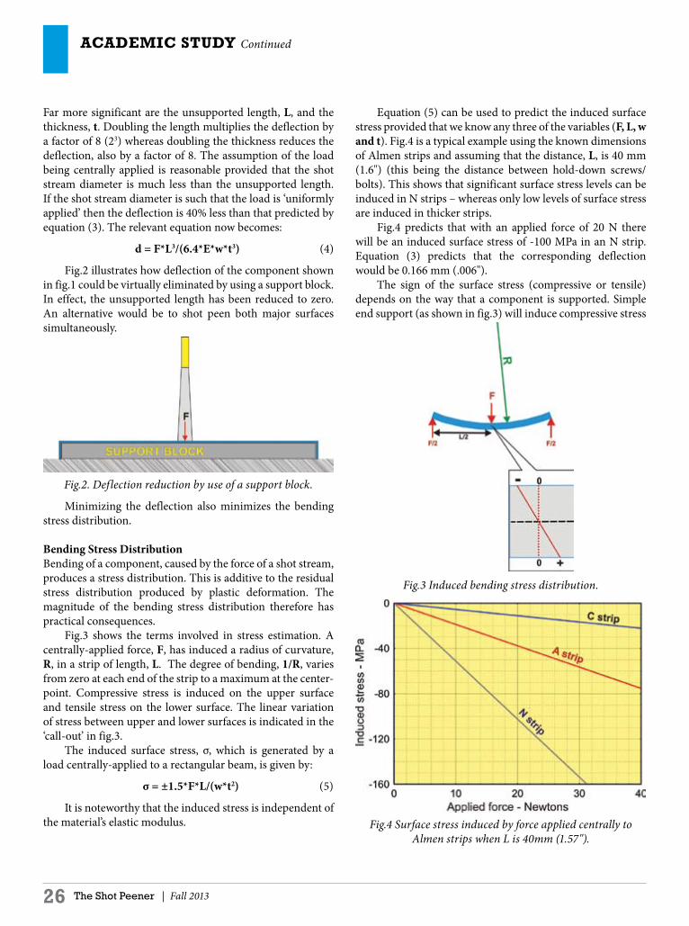
Far more significant are the unsupported length, L, and the thickness, t. Doubling the length multiplies the deflection by a factor of 8 (23) whereas doubling the thickness reduces the deflection, also by a factor of 8. The assumption of the load being centrally applied is reasonable provided that the shot stream diameter is much less than the unsupported length. If the shot stream diameter is such that the load is ‘uniformly applied’ then the deflection is 40% less than that predicted by equation (3). The relevant equation now becomes:
d = F*L3/(6.4*E*w*t3) (4)
Fig.2 illustrates how deflection of the component shown in fig.1 could be virtually eliminated by using a support block. In effect, the unsupported length has been reduced to zero. An alternative would be to shot peen both major surfaces simultaneously.
Fig.2. Deflection reduction by use of a support block.
Minimizing the deflection also minimizes the bending stress distribution.
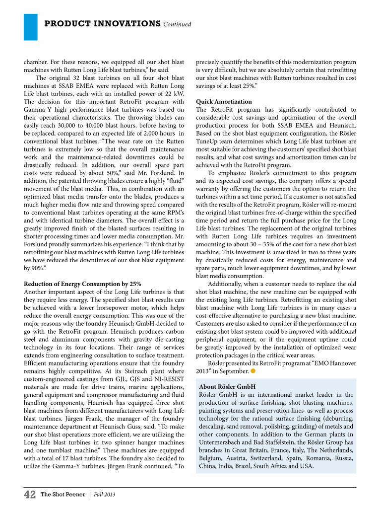
Bending Stress DistributionBending of a component, caused by the force of a shot stream, produces a stress distribution. This is additive to the residual stress distribution produced by plastic deformation. The magnitude of the bending stress distribution therefore has practical consequences. Fig.3 shows the terms involved in stress estimation. A centrally-applied force, F, has induced a radius of curvature, R, in a strip of length, L. The degree of bending, 1/R, varies from zero at each end of the strip to a maximum at the center-point. Compressive stress is induced on the upper surface and tensile stress on the lower surface. The linear variation of stress between upper and lower surfaces is indicated in the ‘call-out’ in fig.3. The induced surface stress, σ, which is generated by a load centrally-applied to a rectangular beam, is given by:
σ = ±1.5*F*L/(w*t2) (5)
It is noteworthy that the induced stress is independent of the material’s elastic modulus.
Equation (5) can be used to predict the induced surface stress provided that we know any three of the variables (F, L, w and t). Fig.4 is a typical example using the known dimensions of Almen strips and assuming that the distance, L, is 40 mm (1.6") (this being the distance between hold-down screws/bolts). This shows that significant surface stress levels can be induced in N strips – whereas only low levels of surface stress are induced in thicker strips. Fig.4 predicts that with an applied force of 20 N there will be an induced surface stress of -100 MPa in an N strip. Equation (3) predicts that the corresponding deflection would be 0.166 mm (.006"). The sign of the surface stress (compressive or tensile) depends on the way that a component is supported. Simple end support (as shown in fig.3) will induce compressive stress
Fig.3 Induced bending stress distribution.
Fig.4 Surface stress induced by force applied centrally to Almen strips when L is 40mm (1.57").
26 The Shot Peener | Fall 2013

Fall 2013 | The Shot Peener 27
4Customizable vertical structure includes up to 12 wheels for consistent, even coverage
4Optional fittings include PLC controlled VFD, magna-valves and rust inhibitor applications
4Cleans all surfaces in one pass through 36”x84” cleaning envelope
4Monorail fitted with up to 37 fixtures accommodating 2-8 parts each
Send us your challenge...Rosler can find a better way.
Rosler Metal Finishing USA, LLC is the leader in mass finishing, shot blasting, automated processes and media - made in the USA.
JVS - Vertical Structure Monorail System
Visit www.rosler.us or call 269-441-3000.
RMT - Multi-Tumbler Machine
RMBD - Tumble Belt Machines
4Batch sizes from 3 to 35 cubic feet
4No machine pinch points to trap or damage small parts
4Easily automated into process lines
4Highly successful applications include shot peening springs, fasteners, and chain compon- ents
4Unequaled flow through tum- bling action
4Many machine configura- tions to suit varied intensity and coverage requirements
4Ideal for shot peening con- necting rods, gears and other components where high vo- lumes and gentle processing are required.
Visit www.rosler.us or call 269-441-3000.

28 The Shot Peener | Fall 2013
ACADEMIC STuDy Continued
bending stress component, bs. Hence the stress system is now given by:
-i = Y + q + rs - bs (8)
Fig.8 illustrates the stress system incorporating all three compressive stress components. The relevant stress system determines both the size of the consequent indentation and the reigning level of ductility. Indent diameter, for an individual impact, will be smaller with increased residual- and bending-stress components and with increasing yield strength. Component ductility, on the other hand, will increase with greater residual- and bending-stress components.
CASE STUDY – ALMEN STRIP PEENING One type of thin component that is familiar to all shot peeners is the Almen strip. For that reason, peening of Almen strips provides an appropriate subject for a case study. This case study starts with a qualitative analysis of what happens to
in the surface being peened. If, however, we have just one end being clamped then the bending will induce tensile surface stresses in the surface being peened. This is illustrated in fig.5.
Fig.5. Shot stream applying a force, F, to an end-clamped strip.
COMBINATIONS OF RESISTANCE, BENDING AND RESIDUAL STRESSESThe first shot particles that indent a surface only have to contend with resistance stresses around each indent, see fig.6. These resisting stresses, - q, are compressive and account for very high component ductility (as discussed in a previous article in this series). For plastic deformation to occur, the shot particle has to exert a compressive stress, - i, that equals the yield strength of the component plus the resistance stress. Hence the stress system is given by:
- i = Y + q (6)
Fig.6. Stress system for initial shot peening indentations.
The stress that has to be imparted by subsequent impacts also depends on whether or not there is a bending stress element. With no bending, subsequent impacts have to overcome a combination of yield strength, resistance stress and the developing surface compressive residual stress, - rs. Hence we have the stress system:
i = Y + q + rs (7) This stress system is illustrated in fig.7. When there is also a compressive bending component, subsequent impacts then have to overcome the quadruple combination of yield strength, resistance stress, the developing surface compressive residual stress, - rs, and the
Fig.7. Stress system with residual stress component added.
Fig.8. Stress system with both residual stress and bending stress components.

Fall 2013 | The Shot Peener 29
THE NEXT GENERATION OF ALMEN STRIPS
Electronics Inc. Almen Strips
p Proven in the field
p Consistent quality
p Repeatable performance
p Trusted worldwide
Electronics Inc. manufactures and maintains the world’s largest Almen strip inventory for worldwidedistribution. EI can provide strips to any specification, from standard MIL specifications to rigid aerospacespecifications. Almen A, N or C strips in GradesSM 3, 2, 1 and I-S are ready-to-use and pre-qualified.
Saturation curves are only as dependable as the strips used to perform the test. If your strips aren’t consistent in hardness and thick-ness, your tests won’t be accurate. Call or email us for our Almen strip consistency performance data—our strips are consistent in hardness and thickness from lot to lot, from year to year.
The EI Numbered Almen Strips with Coverage Check FinishNUMBERING SYSTEM
• Provides a tracking method for meeting specifications and first-in, first-out, ISO and Nadcap requirements
• Allows lot-to-lot comparison for process consistency
• Part of Electronics Inc.’s comprehensive traceability and audit program
• Denotes genuine EI product
COVERAGE CHECK FINISH (U.S. Patent No. 6,568,239)
• Lapses in coverage are easy to check visually
• Contributes to a proper flapper peening technique
• Enhances capabilities of coverage checker tools
The Almen Strip Experts Since 1987
1-800-832-5653 or 1-574-256-5001 | www.electronics-inc.com 56790 Magnetic Drive, Mishawaka, Indiana 46545 USA

30 The Shot Peener | Fall 2013
ACADEMIC STuDy Continued
stream will only partially flatten the N strip. The strip will then be suffering a compressive surface stress throughout further peening. This will reach a maximum of some 50 MPa as indicated by fig.4. When A strips are being peened it is reasonable to suppose that the shot stream will be exerting a greater force than that used for N strips. The maximum as-clamped deflection for a (larger) 20 Newton shot stream is 0.03 mm (.001") with an induced compressive surface bending stress of 40 MPa. With C strips and a 30 N shot stream the values would be 0.007 mm (.0003") and 17MPa. Equation (8) predicts that it becomes progressively more difficult to generate indents as shot peening progresses. The effect would be greater for N strips than for A and C strips. This should be reflected in it taking longer to achieve a given level of coverage. Verification can be obtained by comparing the time, T, which it takes to reach the peening intensity point on a saturation curve – using a fixed intensity of shot stream. Figs. 11 and 12 are examples of saturation curves produced using such fixed shot stream conditions. The ‘fixed conditions’ used in producing the data for figs.10 and 11
an Almen strip during peening and is followed by quantitative illustrations.
Qualitative AnalysisWhen peening of a flat Almen strip begins, the strip cannot bend regardless of the shot stream force. That is because the strip is being supported all along its length. Equation (6) then governs the relevant stress system. After further peening, the strip begins to adopt a convex curvature (see fig.9). Curvature occurs even though the strip is being restrained by four screws/bolts. The strip also develops surface compressive residual stress. During peening, this curvature will be opposed by the bending force being applied by the shot stream, inducing compressive bending stress in the surface being peened. For relatively low levels of coverage, the convex curvature will be completely overcome by the force of the shot stream. Equation (8) now defines the relevant stress system. Further peening may generate a curvature greater than that which can be overcome by the flattening-effect of the shot stream.
Fig.9. Complex curvature adopted by clamped, peened, Almen strip.
This qualitative analysis indicates that indentation becomes increasingly difficult as peening progresses. That means that coverage rates would be expected to decrease to a corresponding degree. The actual extent of this decrease can only be determined experimentally.
Quantitative AnalysisThe deflection of a clamped Almen strip can be estimated using a combination of equations (3) and (4). A combination is needed because the shot stream can no longer be regarded as applying a load at one particular point. The divisor parameter lies somewhere between 4 and 6.4. Fig.10 shows the estimated flattening that can be predicted for three thicknesses of Almen strip and assuming a divisor value of 5.2 (average of 4 and 6.4). Note that the deflection developed during peening of clamped Almen strips is about one-third of the deflection on release from the holding bolts. Consider first an N strip being peened by a shot stream exerting a force of 10 Newtons. The shot stream will fully flatten the N strip against its block until the as-clamped deflection reaches 0.06 mm (.002"). (The prediction is given in fig.10.) With greater as-clamped deflections, the shot
Fig.10. Estimated as-clamped deflection of Almen strips as a function of applied force.
Fig.11. Analyzed Saturation curve for N strips using fixed peening conditions.

Summer 2013 | The Shot Peener 31
MagnaValve®
COLORS
BLACK PANTONE 130
WM 3000-24 The most powerful wheel blast machine media valve on the market
p Flow rate up to 3,000 lb/min (1,361 kg/min) for steel shot
p Flow control for wheels up to 125 Hp
p Remote valve driver for high-temperature environments
p No moving parts for maintenance-free operation
www.electronics-inc.com 1-800-832-5653 or 1-574-256-5001
AC-24Controller
Regulated Media Flow
Control Signal
Desired Motor Current
Motor Current Ammeter Media Accelerated
Media Hopper
MagnaValve
Wheel
The WM 3000-24 and Electronics Inc. AC-24 Controller provide motor
amperage control
Closed loop system
ideal for foundries and other high-volume applications

32 The Shot Peener | Fall 2013
ACADEMIC STuDy Continued
were: S70 shot, 10 lb/min feed rate, 25 psi air pressure, 0.36" nozzle 12" above strips, 90˚ blast angle. For N strips the time, T, was 50% longer than when using A strips - 0.47 cf 0.31. This finding is in agreement with the proposed bending stress effect.
DISCUSSIONIt has been shown that shot stream force can induce
Fig.12. Analyzed Saturation curve for A strips using same peening conditions as for fig.10.
significant deflections and surface stress during peening. The magnitude of these effects depends primarily on the component thickness and on the distance between supports. If the induced surface stress is substantial, then the primary effect will be on the size of the peening indents. Inducing a compressive surface bending stress will reduce the size of a given indent. An induced tensile surface bending stress will have the opposite effect. If the size of peening indents has been significantly affected, then there will be corresponding effects on the measured peening intensity, coverage rate and residual stress profile. Real components will require the application of more complicated equations than those used in this article. Such analysis lies in the province of mechanical engineers for whom mechanics of bending is a core interest. Nevertheless the equations used here do allow estimates to be made for a range of components. Finally, the effects of shot stream force should not be ignored if peeners are confronted with components that are only a few millimeters thick. ●

Fall 2013 | The Shot Peener 33
2101 W. Cabot Boulevard, Langhorne, PA 19047, USA • 215.752.8800 • Fax 215.752.9373 [email protected] • www.empire-airblast.com
Are You Prepared for a NADCAP Audit?
Empire robotic blast systems ensure your parts are processed in compliance with the strictest quality standards.
Empire Has It All!Automated Blast Systems
Blast CabinetsBlast Rooms
Portable Blasters
Supplying spare parts for shot blast machines and shot peening accessories for the automotiveand aerospace industriessince1991
Av. De las Granjas No. 61 - 3 Col. Jardín Azpeítia, Azcapotzalco
C.P. 02530 México, D.F., Tel. 011-52-55-5355-0947, Fax 011-52-55-5355-6391
E-mail: [email protected]
SHOT BLAST PARTSCHAIN LINKSCUT WIRE SHOT
BLAST WHEELS
CAST NUTS
WHEEL LINERS
CONVEYOR FLIGHTS
MANGANESE
PLATE 11-14%
ALMEN STRIPS
SHOT PEENING
PRODUCTS
STRIP
HOLDERS
MAGNAVALVES
ALMEN GAGES
ALMEN MINI STRIPS3M FLAPPS SHOT PEENING
WORKSHOPSFLAPPER PEENING
KITS

PRODuCT DEVELOPMENTToyo Seiko | www.toyoseiko.co.jp
34 The Shot Peener | Fall 2013
New Application and Measurement Fixture for the Coverage Checker™
TOyO SEIkO is introducing two new applications and a new fixture for measuring small samples for their handheld coverage measurement device, the Coverage Checker™.
The New Applications1.1 Surface texture before weldingAutomobile suppliers are continually required to decrease costs. For example, due to its high costs, the cutting process is destined to be replaced with press or cold forging. If welding is done after the press process, this provides an opportunity to use shot peening, since welding quality can be improved by putting shot-peened dents on the surface of the part. When shot peening (or shot blasting) is applied to this process, its quality verification can only be done by visual inspection. Therefore, Coverage Checker™ is an ideal tool to inspect the coverage. It will help prevent poor welds and also enable the shot peener to use the minimum amount of shot to obtain the desired results. Coverage has a strong correlation with welding quality, and therefore, we can monitor the welding quality with the Coverage Checker™. See Fig.1.
Fig.1 Images captured by Coverage Checker™
1.2 Shot blasting before powder coatingShot blasting is used to remove oxidized scale after heat treatment and also to make a roughened surface for powder
coating. Shot blasting has a positive affect on coating quality, but visual inspection was the only way to evaluate its results before the development of the Coverage Checker™. Now Coverage Checker™ makes it possible to verify the quality of shot blasting. Since the surface to be measured will be covered with black oxidized scale after heat treatment, the blasted area is captured as white area in the Coverage Checker™ image. Please see Fig 2 for an image captured by Coverage Checker™. It is able to judge the subtle difference easily by quantifying the pixel count of white area.
Acceptable Unacceptable
Fig.2 Quantifying blasted area by Coverage Checker™
New Measurement System2.1 Fixture for measuringSince the purpose of the Coverage Checker™ is to measure coverage onsite, it is designed to press the attachment nozzle against the object to be measured. However, it was difficult to use when the object was very small, so Toyo Seiko developed a fixture to measure small samples. (See Fig.3 on page 36.) The sample and Coverage Checker™ are not touching each other in the fixture. Before this new system, we had to adjust the angle and distance of the sample with a nozzle. Now, if you are measuring parts with the same dimension and shape, you only need to set the adjust handle in advance and then
100% Coverage 95% Coverage (Marginal)
88% Coverage (Unacceptable)

Fall 2013 | The Shot Peener 35 Winter 2013 | The Shot Peener 35
AutomatedPeen Forming
Solutions
KSA Kugelstrahlzentrum Aachen GmbH · Weststraße 22-24 · 52074 Aachen · Germany
Automated Peen Forming Solutionswww.ksa.de.com
KSA_Anz_8-2012_end.indd 1 07.09.12 12:17

PRODuCT DEVELOPMENT Cont.
36 The Shot Peener | Fall 2013
a subsequent adjustment isn’t required. The LED light source provides enough light to shut out the outside light. The fixture enables a fast and stable measurement.
2.2 Checking KitA coverage sample piece (100~42%) made of an aluminum Almen strip is attached to each Coverage Checker™ as a standard sample. This standard sample is for checking if Coverage Checker™ shows the correct result for this sample every time. However, since there is coverage distribution depending on sample’s measuring point, it might not always be the same result, and its reliability was not enough for a daily check. We then developed a standard sample fixture (Fig.4). Using this fixture, you can fix the measuring point of the standard sample and it guarantees that you can check the coverage by the same measuring point every time. This fixture improves the reliability of Coverage Checker™. ●
Fixture Almen strip applied
Fig.4 Standard sample fixture
Take Control of Your MediaWITH PROFILE SPIRAL SEPARATORS
REMOVE broken media, leaving predominatelyround media for a controlled, effective shot peening process
SEPARATE round from non-roundmetal abrasives, metal shot, ceramic beads, glass beads and more
SAVE money on media—recycle it for a cost savings
PROTECT expensive parts from damage by broken media
LIMIT wear to machine parts from broken media
EXCEED SAE AMS 2430 requirements
Call 1-763-428-5858 today
1-763-428-5858 www.profile-ind.com | [email protected] 13251 George Weber Drive, Rogers, Minnesota USA 55374
Fig 3 Measurement system for small samples
Coverage Checker
HandleAdjustment
Sample
Slot for Sample
Precision shot peen masks and fixtures for the aerospace and commercial sectors
Timely quoting • Competitive lead times An ISO 9001:2000 Certified Company
Quality Engineering Inc. Tel: 203-269-5054 Fax: 203-269-9277 Web: www.qes1.com
122 North Plains Industrial Road, Wallingford, CT 06492
For Quotations: [email protected]


38 The Shot Peener | Fall 2013
2013USA Shot Peening and Blast Cleaning Seminar, Workshop and Tradeshow
Scottsdale, ArizonaOctober 15–17 • The Chaparral Suites
• Innovative shot peening training since 1991• Classroom instruction by industry experts• Ideal for engineers, machine operators, foremen, and supervisors• Achievement exams for Shot Peening Levels 1, 2 and 3, and
Rotary Flap Peening• Opportunity to meet peers from around the world• Trade show with world-class products and services
Receive recognition for achieving a higher level of shot peening education. Seminar, workshop and on-site training attendees areeligble to take our FAA-accepted shot peening and rotary-flap peening achievement exams.
More information and online registration at www.shotpeeningtraining.com or call (574)256-5001 or 1-800-832-5653
Improve your skills,reach your professional goals
Learn the mechanics of the shot peening process, how to do it correctly and how to
inspect the completed process
Audit prepration training, FAA-accepted courses,
Nadcap Partner in Education
On-site training programs are also availableTrain on your equipment • Can be customized • Includes facility and equipment review
Training can be held any time of year • Ideal for five or more employees

Fall 2013 | The Shot Peener 39
CeramicsTungsten Carbide
Silicon CarbideBoron Carbide
Sylacon
We export our quality products
worldwide
INSERTS NOZZLES
Toll Free: 1-877-382-5278 (USA & Canada) Toll: 815-788-8660 Fax: 815-788-8662
Web: www.everblast.com • Email: [email protected] Inc. • 125 Erick Street, #A112 • Crystal Lake, Illinois 60014 USA
Visit our website

PRODuCT INNOVATIONSRösler Oberflächentechnik GmbH | www.rosler.com
40 The Shot Peener | Fall 2013
Rutten Long Life Blast Turbines by RöslerTo stay competitive in today’s global markets, companies must continually optimize their manufacturing operations. Retrofitting Rösler shot blast machines with Rutten Long Life blast turbines will improve the cost efficiency of virtually any shot blast operation. Due to their unique design, these patented high performance turbines yield energy savings of over 25%. The 30,000 to 40,000 hours of service life of the throwing blades results in significantly higher equipment uptimes and drastically reduces maintenance and spare parts costs. Many companies like Swedish steel producer SSAB or the German foundry Heunisch GmbH have taken advantage of the Rösler RetroFit program to increase the productivity and efficiency of their shot blast operations. Surface treatment machines are subject to wear rates. This is especially true for shot blast equipment that runs in multiple shifts, often resulting in long equipment downtimes with a loss of production and high maintenance and operating costs. Another cost factor is the high energy consumption of these machines. In many cases, a systematic equipment modernization will not only provide state-of-the art technology, but will also greatly improve the overall cost efficiency. The “TuneUp” program, developed by Rösler Oberflächentechnik GmbH, deals exclusively with the optimization and the technical overhaul of existing shot blast machinery irrespective of make or model. This program also includes the retrofitting of blast machines with Rutten Long Life turbines for which Rösler is not only holding the respective patents, but is also the manufacturer and exclusive supplier of spare and wear parts. These highly unique high performance turbines are available with Curved-C and Gamma-Y throwing blades. The latter have two working surfaces arranged in a “Y” shape allowing shot blasting in both rotational directions of the turbine.
Downtime Reduced 90% and Spare Part Costs Reduced 50%The Swedish SSAB AB, one of the world’s leading suppliers of high-strength steel, decided to modernize the shot blast equipment at its SSAB EMEA plant in Oxelösund. The company has approximately 8,100 employees in 45 countries. It produced about5,500 thousand metric tons of crude steel in 2012. The Oxelösund plant is considered one of the most important producers of tempered steel in the world. One of SSAB AB’s production lines manufactures wear-resistant Hardox steel plates and sheets. Prior to tempering, the raw material undergoes a blast cleaning process for which the line is equipped with two shot blast machines. Two additional shot blast machines are integrated into the painting line. Five maintenance and repair teams work seven days a week around the clock to ensure the line runs smoothly with a minimum of downtime. Kent Forslund is the maintenance manager for this production line and is responsible for the job scheduling and the cost efficiency of the equipment. “Our four blast machines are from three different suppliers and the original blast turbines were generally wearing very fast. This required a lot of maintenance work, which frequently resulted in long equipment downtimes and very high spare part costs. In addition, it was possible that a blast turbine could completely disintegrate, causing damage to the other blast turbines and the blast
The Rutten Long Life Blast Turbine
The Rutten’s patented Curved-C turbine throwing blade produces a significantly
higher operational efficiency
Gamma-Y® blades have a service life of 30,000 to 40,000 blast hours compared
to an average of 2,000 hours for conventional turbines

Fall 2013 | The Shot Peener 41
Shot & Grit Stainless Shot
AMASTEELFROM ERVIN INDUSTRIES
(800) 748-0055
AMACASTFROM ERVIN INDUSTRIES
(800) 748-0055
T H E B E S T Q U A L I T Y I N T H E I N D U S T R Y
www.cwst.com
World Leaders in Surface Engineering
Technologies
METAL IMPROVEMENT COMPANY
• Large network of controlled
shot peening facilities
• On-site shot peening, laser peening
• All major industry & OEM accreditations
• 50 job shop locations worldwide
IMR TEST LABS
• Metallurgical services
• Failure analysis
• Fatigue/corrosion/mechanical testing
• 5 locations in 3 countries
E/M COATING SERVICES
• Dry film lubricants
• Corrosion/chemical resistant coatings
• Phospate, Chem-Film, Ti anodize,
Microseal®
• 12 locations in 5 countries
FW GARTNER / CWST THERMAL SPRAY
• Thermal spray & laser PTA/cladding
• Precision machining & surface finishing
• Protect & reclaim functional surfaces
• 6 locations
[email protected] 262-893-3875
PRODuCT INNOVATIONS Continued
42 The Shot Peener | Fall 2013
precisely quantify the benefits of this modernization program is very difficult, but we are absolutely certain that retrofitting our shot blast machines with Rutten turbines resulted in cost savings of at least 25%.”
Quick AmortizationThe RetroFit program has significantly contributed to considerable cost savings and optimization of the overall production process for both SSAB EMEA and Heunisch. Based on the shot blast equipment configuration, the Rösler TuneUp team determines which Long Life blast turbines are most suitable for achieving the customers’ specified shot blast results, and what cost savings and amortization times can be achieved with the RetroFit program. To emphasize Rösler’s commitment to this program and its expected cost savings, the company offers a special warranty by offering the customers the option to return the turbines within a set time period. If a customer is not satisfied with the results of the RetroFit program, Rösler will re-mount the original blast turbines free-of-charge within the specified time period and return the full purchase price for the Long Life blast turbines. The replacement of the original turbines with Rutten Long Life turbines requires an investment amounting to about 30 – 35% of the cost for a new shot blast machine. This investment is amortized in two to three years by drastically reduced costs for energy, maintenance and spare parts, much lower equipment downtimes, and by lower blast media consumption. Additionally, when a customer needs to replace the old shot blast machine, the new machine can be equipped with the existing long Life turbines. Retrofitting an existing shot blast machine with Long Life turbines is in many cases a cost-effective alternative to purchasing a new blast machine. Customers are also asked to consider if the performance of an existing shot blast system could be improved with additional peripheral equipment, or if the equipment uptime could be greatly improved by the installation of optimized wear protection packages in the critical wear areas. Rösler presented its RetroFit program at “EMO Hannover 2013” in September. ●
chamber. For these reasons, we equipped all our shot blast machines with Rutten Long Life blast turbines,” he said. The original 32 blast turbines on all four shot blast machines at SSAB EMEA were replaced with Rutten Long Life blast turbines, each with an installed power of 22 kW. The decision for this important RetroFit program with Gamma-Y high performance blast turbines was based on their operational characteristics. The throwing blades can easily reach 30,000 to 40,000 blast hours, before having to be replaced, compared to an expected life of 2,000 hours in conventional blast turbines. “The wear rate on the Rutten turbines is extremely low so that the overall maintenance work and the maintenance-related downtimes could be drastically reduced. In addition, our overall spare part costs were reduced by about 50%,” said Mr. Forslund. In addition, the patented throwing blades ensure a highly “fluid” movement of the blast media. This, in combination with an optimized blast media transfer onto the blades, produces a much higher media flow rate and throwing speed compared to conventional blast turbines operating at the same RPM’s and with identical turbine diameters. The overall effect is a greatly improved finish of the blasted surfaces resulting in shorter processing times and lower media consumption. Mr. Forslund proudly summarizes his experience: “I think that by retrofitting our blast machines with Rutten Long Life turbines we have reduced the downtimes of our shot blast equipment by 90%.”
Reduction of Energy Consumption by 25%Another important aspect of the Long Life turbines is that they require less energy. The specified shot blast results can be achieved with a lower horsepower motor, which helps reduce the overall energy consumption. This was one of the major reasons why the foundry Heunisch GmbH decided to go with the RetroFit program. Heunisch produces carbon steel and aluminum components with gravity die-casting technology in its four locations. Their range of services extends from engineering consultation to surface treatment. Efficient manufacturing operations ensure that the foundry remains highly competitive. At its Steinach plant where custom-engineered castings from GJL, GJS and NI-RESIST materials are made for drive trains, marine applications, general equipment and compressor manufacturing and fluid handling components, Heunisch has equipped three shot blast machines from different manufacturers with Long Life blast turbines. Jürgen Frank, the manager of the foundry maintenance department at Heunisch Guss, said, “To make our shot blast operations more efficient, we are utilizing the Long Life blast turbines in two spinner hanger machines and one tumblast machine.” These machines are equipped with a total of 17 blast turbines. The foundry also decided to utilize the Gamma-Y turbines. Jürgen Frank continued, “To
About Rösler GmbH Rösler GmbH is an international market leader in the production of surface finishing, shot blasting machines, painting systems and preservation lines as well as process technology for the rational surface finishing (deburring, descaling, sand removal, polishing, grinding) of metals and other components. In addition to the German plants in Untermerzbach and Bad Staffelstein, the Rösler Group has branches in Great Britain, France, Italy, The Netherlands, Belgium, Austria, Switzerland, Spain, Romania, Russia, China, India, Brazil, South Africa and USA.
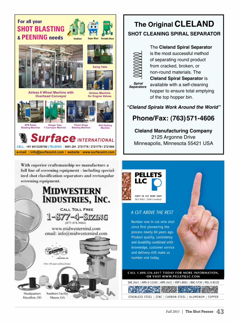
Fall 2013 | The Shot Peener 43
The Original CLELANDSHOT CLEANING SPIRAL SEPARATOR
SpiralSeparators
“Cleland Spirals Work Around the World”
Phone/Fax: (763)571-4606
Cleland Manufacturing Company2125 Argonne Drive
Minneapolis, Minnesota 55421 USA
The Cleland Spiral Separator is the most successful method of separating round product from cracked, broken, or non-round materials. The Cleland Spiral Separator is available with a self-cleaning hopper to ensure total emptying of the top hopper bin.
Number one in cut wire shot since first pioneering the process nearly 60 years ago. Product quality, consistency and durability combined with knowledge, customer service and delivery still make us number one today.
SAE J441 | AMS-S-13165 | AMS 2431 | VDF1-8001 | BAC-5730 | MIL-S-851D
STAINLESS STEEL | ZINC | CARBON STEEL | ALUMINUM | COPPER
A CUT ABOVE THE REST
ISO 9001: 2000 Certified
PELLETS_QTR_PAGE.indd 1 5/7/06 4:24:26 PM

44 The Shot Peener | Fall 2013
INDuSTRy NEWS
Airblast AFC Is On the
Right TrackAIRBLAST AFC has completed work on a $1.4 million project for a large rail group in Ohio, USA, which repairs, sells, manages, and leases a fleet of almost 23,000 various types of railcars and locomotives. Airblast AFC is a joint venture between Airblast Ltd and AFC Finishing Systems (AFC) who has been manufacturing paint spray booths, air make-up units, powder coating equipment and related equipment throughout North America since 1967. The new facility includes a blast booth, paint booth and drying booth for the maintenance of the railcars. The three booths are all approximately the same size at 25 ft. wide by 90 ft. long, allowing plenty of space for the larger railcars. The new facility features four blast machines which allow up to four operators to work on a job and personnel lifts to ensure the safety and comfort of the workers. Without a doubt, the most exciting feature of this installation is its innovative Airflex Recovery Floor for the automatic recovery of abrasive materials throughout blast booths. The Airflex Floor is made of modular “flexible” scraper corridors of six standard widths that can be produced to practically any length, giving enormous flexibility to recover from virtually any floor area. Unlike many other abrasive recovery systems where civil engineering costs and/or power consumption often dictate only partial floor coverage, the Airflex Recovery Floor utilizes 100 percent of the floor space meaning that operators do not have to waste any time manually recovering abrasive. The system, regularly deployed at existing factory floor level when a short step into the booth is acceptable, requires less than 6" deep ground works to achieve a full recovery floor flush to the existing factory floor. Its other great advantage is minimal power consumption. In this case, the entire floor measuring 25 ft. wide x 90 ft. long with four blasters working at up to 150 psi, ran on only 12 hp. The project began in February 2013 amid freezing temperatures and heavy snow fall. The Airblast AFC team began work on the booths, even though it meant working outside in sub-zero temperatures, and the project was completed within 11 weeks. With the success of this project, Airblast AFC has high hopes that they will be able to provide more services for the rail industry in the future. To find out how Airblast AFC could fulfil all your blasting and painting needs, give us a call at (800) 331-7744 or visit our website at www.airblastafc.com
About Airblast AFCAirblast AFC is a joint venture between AFC Finishing Systems (AFC) and Airblast Ltd (Airblast) in the United Kingdom. Airblast has been providing blast booths and related equipment throughout Europe for over 30 years. Their customer list is wide and varied from many diverse industries, including aerospace, automotive, rail and wind power. They have a proven track record in the engineering and design of quality blast equipment utilizing the latest available technology. AFC has been manufacturing paint spray booths, air make-up units, powder coating equipment, etc. since 1967. AFC and Airblast are proud to partner together in order to provide the manufacturing, sales, installation and support of Airblast engineered equipment throughout North America.
The Airflex Blast Room Media Recovery System by Airblast AFC
Internal Shot Peening and Its
ApplicationsTHE MAJOR APPLICATION of shot peening is the improvement of fatigue characteristics, and applications like metal forming, straightening, improving resistance to stress corrosion, and testing the adhesion of plated deposits of silver on steel. Less known, but just as useful, is when shot peening is used to roughen the inside of a pipeline. A good example is a pneumatic conveying system for the transportation of plastic pellets. Pneumatic conveyor tubing is usually made of stainless steel or aluminum alloy. It is used to transport plastic pellets at the facilities of molding companies or at various production, blending and distribution sites. The velocity of the pellets results in friction, heat and lost production. When these granulates get into contact with the smooth pipe wall, the friction pressure and

Summer 2013 | The Shot Peener 451-800-832-5653 or 1-574-256-5001 www.electronics-inc.com 56790 Magnetic Drive, Mishawaka, Indiana 46545
• Patented magnetic grip and end stops (U.S. Patent No. 5,297,418)
• An easy-to-read display
• .0001'' (.001 mm) resolution
• SPC data port
• Convenient battery replacement
• Calibration services or block kit available (U.S. Patent No. 5,780,714)
• Ergonomic design
• One-year warranty
The World’s Finest Almen Gage meets:
SAE J442
AMS 2430
AMS 2432and many more gagerequirements for the aerospace industry
The World’s Finest Almen Gage
The Industry-Standard Tool for Measuring Intensity
Also available: The patentedAlmen Mini-Gage and Mini-Strips
INDuSTRy NEWS Continued
46 The Shot Peener | Fall 2013
the increased temperatures may lead to a partial plastification of the granulates. As a result, there is first the formation of a film and then, subsequently, of fibers called “angel hair” in the pipes and the pipe elbows. The consequences are material loss, impurities and even a complete clogging of the pipelines. Angel hair accounts for millions of pounds of lost and/or contaminated production each year. The aim is therefore to avoid angel’s hair by a specific roughening of the surface. When the inside of pipeline is roughened by shot peening, the polymer pellets bounce or roll instead of sliding along the inside of the pipe. The pellets’ contact with the side of the pipe is shortened and formation of angel hair is prevented. Shot peening of pipes has been found to be superior to other internal treatments of the tubing, and is often more economical. Plus, it can be applied on-site. The shot-peened finish has the added benefit of work hardening (when stainless or aluminum piping is used), thus extending the life of the surface treatment. Table One shows test results from six different internal pipe treatments. A lower value of fines per 100,000 lb conveyed is desirable. Shot peening resulted in one-third less fines than that of the next closest finish. Internal shot peening is a proven application in the dairy/cheese, oil/gas, chemical and plastics industries.
TABLE ONE
Vikas MetalsVikas Metals is a pioneer in the internal shot peening industry. They specialize in internal shot peening for stainless steel, carbon steel and aluminum pipes, bends, tailor-made long radii elbows and pipe pittings, supplied per customer specifications. The Vikas teams are committed to achieve the most cost-effective shot peening job shop services. Their internal shot peened products are mainly supplied to the pneumatic conveying industry engaged in preparing conveying systems for the transportation of plastic pellets.
Shot-Peened PipesVikas Metals’ innovative methods for the internal surface roughening of pipes prevents costly production failures due to angel’s hair. Their plant is equipped with automatically controlled shot peening machines for a wide range of components up to one meter in diameter. The finish is consistent and covers 100% of the internal surface of the pipe.
The overall quality of the pipeline system may be increased by special types of inner surfaces. The quantity and the quality of the granulated material as well as the kind and velocity of the transport require individual depths of roughness. Vikas Metals uses different techniques to achieve the defined degree of roughness of the inner pipe surfaces. Shot-Peened ElbowsElbows with long radii ensure a safe, clean and careful transport of products. An essential aspect of the pneumatic conveying technology is the fact that pipe elbows with long radii are used to reduce the impact of granulates with the pipe elbow, thus avoiding possible damage to both the goods and the pipe walls. This means that the transport becomes safer and cleaner. Moreover, the demixing of the carrying air and of the goods due to the transport will be reduced. The homogenous conveying of the material avoids the formation of clogging and the resulting pressure losses. Vikas Metals can supply elbows of any radii and of all required angles. The usual radius is 5 to 10 times the pipe diameter. Tangents, either at one end or at both ends, can be considered during production. The company offers tailor-made long radii pipe elbows, as per required radius and tangent, with smooth or especially roughened inner surfaces. Long radii elbows are available in stainless steel, carbon steel and aluminium. For more information, call +91-9885977337 (ask for V.C. Chandan) or send email to [email protected].
Treatment Fines (grams/100,000 lb conveyed)
Directional Shot Peened 1,629Smooth Mill Finish 4,886Spiral Groove Pipe 6,518Sandblasted Pipe 7,145
Polyurethane Coated 7,215Medium Scored Pipe 13,887
www.theshotpeenermagazine.com
Download the latest issue Get advertising rates Request a free subscription Read past issues

Fall 2013 | The Shot Peener 47
More efficient parts processing? Procisely!® PRIMS Pro® gives engineersand operators the most advanced and flexibleprocess controller ever. PRIMS Pro® is Windows-based and procisely
customized for your shot peening operations.
Part & program manager• Queue parts before processing, or while others process
• Search by easily sorting through large quantities of parts
• Select and define multiple motion control or surface functions
• Modify or review part programs
Preventive maintenance• Auto-sort based on next item required
• All-in-one maintenance scheduler, historian, and advisor
Multi-level security system• Customize permission levels by user log-in
• Control modifications to process parameters and part data
• Limit who can reset PM items or run alarms
PRIMS Pro automates process control, monitoring, and data-logging for key parameters.
It’s the ideal monitoring software for production, overhaul and repair, and R&D.
Learn more at:
progressivesurface.com
PS-full pg PRIMS Pro ad-ShotPeener.indd 1 3/23/12 8:55 AM
