fairway for propeller design? - sarc · fairway for propeller design? bastiaan veelo, ... modelling...
TRANSCRIPT

454
Fairway for Propeller Design?
Bastiaan Veelo, SARC, Trondheim/Norway, [email protected]
Abstract
This paper reports on a case study of the applicability of Fairway for the modelling and design of propeller blades. Fairway is a geometric modeller, tailored at the computer aided-design of ship hulls and other floating structures, that avoids the limitations of NURBS patches by not using them; instead it defines a surface by transfinitely interpolating a non-regular network of curves. Compared to the modelling of a ship hull, the modelling of a propeller blade differs with higher requirements on accu-racy and curvature continuity, while its geometry is typified by large variations in curvature.
1. Introduction In computer graphics and computer-aided design (CAD), the class of surfaces denoted to be of arbi-trary topology is typically comprised of the surfaces that cannot be covered completely by a regular patchwork of four-sided regions without overlaps, degenerate sides or degenerate corners. Many ship hulls are of this class. The blades of most open propellers fall into this class as well, and because the CAD system Fairway is specifically devised to deal with surfaces of arbitrary topology, it may be well worth asking: “How about using Fairway for propeller design?” In the following, an introduction is given of how propeller blades are usually modelled, accompanied with relevant technical background on geometric modelling. The challenges of this approach will be covered in detail. 1.1 Common methodology The usual way of constructing a CAD model of a propeller blade is the skinning or lofting of a NURBS surface through cylindrical sections of different radii through the propeller blade in axial direction, Nowacki et al. (1995). The radius of each section is defined dimensionless as the ratio 𝑟/𝑅, where 𝑟 is the radius of the section cylinder and 𝑅 equals half the propeller diameter. The section curves are NURBS fitted though points on the propeller blade at given 𝑟/𝑅 that are gen-erated by specialised algorithms. These algorithms typically modify common foil profiles such as the NACA series, Carlton (2012), to specified distributions of pitch angle, chord length, thickness, cam-ber, rake, skew and blends into a specific nose radius, as a function of 𝑟/𝑅. The process of NURBS surface skinning, Piegl and Tiller (1995), involves making the section splines compatible in terms of degree and knot vector by the principles of loss-less degree raising and knot insertion. This can potentially increase the number of control points significantly (by a factor propor-tional to the square of the number of sections) so that it is advisable to fit the data points on each sec-tion with splines of identical degree and parameterisation and that data points are equal in number and proportionally spaced across sections. Care must be taken that under these constraints the fit is suffi-ciently accurate and fair. Then for each control point on a section an interpolating NURBS curve of fixed degree and parameterisation is computed that connects the corresponding control points on all other sections. The resulting set of control points form the control network of the skinned NURBS surface. This process is typically implemented in CAD software and beyond the control of the user. 1.2 Challenges and problems NURBS surfaces are defined on a rectangular bi-parametric domain (𝑢, 𝑣). The original section curves are now isoparametric lines on the skinned surface, meaning that each section curve is de-scribed by the skinned surface for some fixed 𝑢 while 𝑣 varies along the section. The isoparametric lines in the orthogonal parametric direction (fixed 𝑣) run across corresponding positions on successive sections: from the blade root they initially fan out with increasing chord length, then turn towards

455
each other to eventually implode in a singularity at the blade tip. This implies various problems, some of which can be solved in theory but not in practice; for others there exist a practical solution that lacks theoretical perfection. Firstly, the interpolation in 𝑣 direction by the skinning algorithm is typically performed without tak-ing into account, or the possibility to define, any boundary conditions of tangency or curvature. That is that the 𝑣 isoparametric lines tend to converge in a cusp at the blade tip and that there is a sharp discontinuity in the blade outline where the leading edge meets the trailing edge, Fig. 1. By the same principle the thickness of the blade tends to become too thin too quickly.
In theory this can be remedied by constraining the last two control points of the interpolating splines in 𝑣 direction in a common tangent plane. It should even be possible to achieve geometric curvature continuity at the singularity by choosing appropriate weights for the control points of rational splines, in the same way that a single NURBS patch is capable of describing a perfect sphere, Rogers and Adams (1990). However, users are not expected to have this kind of theoretical background, and I know of no skinning implementation that exposes these kinds of internals or provides some kind of interface for defining boundary conditions. The pragmatic approach to preserve the blade outline and thickness as much as possible is to reduce this effect by providing more sections towards the tip at smaller steps of 𝑟/𝑅, Kaplan and MacPher-son (2014). This, together with the ever shorter chord length towards the tip, inherently leads to an-other problem: a very high density of control points, much, much higher than in any other region of the blade – without there being a fundamental difference in local geometry. This imposes very high accuracy requirements on the input data and jeopardises the fairness in the tip region. In any case this rules out manual manipulation of control points and tweaking the tip geometry is thereby out of the question. The third problem is due to the highly skewed mapping between the parametric space of the NURBS patch and Euclidean space: the isoparametric lines in 𝑢 and 𝑣 direction, which are orthogonal in par-ametric space, run almost parallel to each other along the rim in the tip region of the blade. This can easily lead to ripples at the slightest inaccuracy, and it is practically impossible to fair these away by hand. And fourthly, the singularity at the blade tip, together with the tightly spaced sections and rapidly changing chord length, thickness and section shape, produce highly concentrated and severe curvature at the back, Kaplan and MacPherson (2014). Since there is no way to address this with decent model-ling practices due to the infestation of control points and skewed parameterisation, curvature is effec-tively out of control and the problem can only be worked around. The current state of the art, Kaplan
Fig. 1: Isoparametric lines of a skinned propeller blade (grey). Lack of boundary conditions can cause deviation from a curvature continuous (desired) blade outline (black).
456
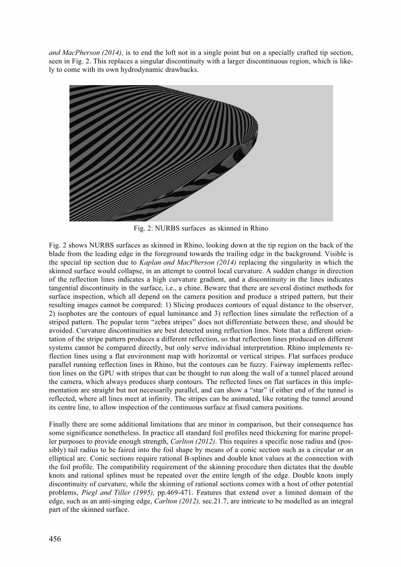
and MacPherson (2014), is to end the loft not in a single point but on a specially crafted tip section, seen in Fig. 2. This replaces a singular discontinuity with a larger discontinuous region, which is like-ly to come with its own hydrodynamic drawbacks.
Fig. 2 shows NURBS surfaces as skinned in Rhino, looking down at the tip region on the back of the blade from the leading edge in the foreground towards the trailing edge in the background. Visible is the special tip section due to Kaplan and MacPherson (2014) replacing the singularity in which the skinned surface would collapse, in an attempt to control local curvature. A sudden change in direction of the reflection lines indicates a high curvature gradient, and a discontinuity in the lines indicates tangential discontinuity in the surface, i.e., a chine. Beware that there are several distinct methods for surface inspection, which all depend on the camera position and produce a striped pattern, but their resulting images cannot be compared: 1) Slicing produces contours of equal distance to the observer, 2) isophotes are the contours of equal luminance and 3) reflection lines simulate the reflection of a striped pattern. The popular term “zebra stripes” does not differentiate between these, and should be avoided. Curvature discontinuities are best detected using reflection lines. Note that a different orien-tation of the stripe pattern produces a different reflection, so that reflection lines produced on different systems cannot be compared directly, but only serve individual interpretation. Rhino implements re-flection lines using a flat environment map with horizontal or vertical stripes. Flat surfaces produce parallel running reflection lines in Rhino, but the contours can be fuzzy. Fairway implements reflec-tion lines on the GPU with stripes that can be thought to run along the wall of a tunnel placed around the camera, which always produces sharp contours. The reflected lines on flat surfaces in this imple-mentation are straight but not necessarily parallel, and can show a “star” if either end of the tunnel is reflected, where all lines meet at infinity. The stripes can be animated, like rotating the tunnel around its centre line, to allow inspection of the continuous surface at fixed camera positions. Finally there are some additional limitations that are minor in comparison, but their consequence has some significance nonetheless. In practice all standard foil profiles need thickening for marine propel-ler purposes to provide enough strength, Carlton (2012). This requires a specific nose radius and (pos-sibly) tail radius to be faired into the foil shape by means of a conic section such as a circular or an elliptical arc. Conic sections require rational B-splines and double knot values at the connection with the foil profile. The compatibility requirement of the skinning procedure then dictates that the double knots and rational splines must be repeated over the entire length of the edge. Double knots imply discontinuity of curvature, while the skinning of rational sections comes with a host of other potential problems, Piegl and Tiller (1995), pp.469-471. Features that extend over a limited domain of the edge, such as an anti-singing edge, Carlton (2012), sec.21.7, are intricate to be modelled as an integral part of the skinned surface.
Fig. 2: NURBS surfaces as skinned in Rhino

457
2. Fairway’s methodology Fairway is a geometric modeller developed by SARC B.V., conceived specifically to circumvent the limitations of NURBS surfaces in the design of curved shapes of arbitrary topology. Although Fair-way deals with solids and their surfaces, its modelling interface is constructed around the manipula-tion of curves, Fig. 3. An essential property of Fairway is its functionality for curve fairing; in fact Fairway is frequently applied to fair ship hull models produced on other systems to make them fit for production. Equally powerful is its ability to derive a surface description from the curves, which pres-ently is primarily used for visualisation, the interpolation of new section curves and the computation of stretch in shell plate expansions.
Fig. 3: Excerpt of the Fairway GUI showing the panes for curve manipulation
Because the manufacturing process for a marine propeller is so very different from the construction of a ship hull, Fairway is not obviously an appropriate tool for propeller modelling. In ship construction the contour of stiffeners and profiles, of plates and of templates is all-important and governed by curves, for which Fairway is the perfect fit. In earlier days, even propeller moulds were carved using flat patterns and templates. But nowadays, high quality surface models are required in support of NC milling and robot grinding and polishing. As we will see, this is not what Fairway excels at, yet. 2.1 Fairway internals The curves that describe the surface of a solid model in Fairway are NURBS curves whose only re-quirement is that they start and end on another curve in the model. Typically, curves run along exten-sive parts of the surface, intersecting many other curves, together forming a smoothly curved network. There is no regularity requirement on the network, and the holes or meshes in it can have any number of sides. The surface description is then formed by filling each mesh in the network by a transfinite interpolation of its bounding curve sections. Unlike a NURBS surface patch, which can only be made to fit a finite number of arbitrary distinct points, a transfinite interpolation exactly matches its bound-ing curves at a non-denumerable (transfinite) number of points, i.e., everywhere. The curves can have arbitrary shape and definition, as long as they are parametric. Most importantly, the curves that bound the same interpolating patch may have a completely independent definition —contrary to NURBS patches where the same number of control points and the same parameterisation applies to the whole surface from one side of the patch to the opposite side, which is the cause of the control point infesta-tion near the tip of a skinned propeller blade. A consequence of transfinite interpolation is that there are no gaps between surface patches, by which Fairway is capable of producing triangulations that are absolutely seamless. (Note the gap in the Rhino model of Fig. 2. Many modellers like Rhino have special tools to check connecting surfaces for gaps, which Fairway conveniently can do without.) Adjacent surface patches in a Fairway model are given the same tangent across their shared bounda-ries by having them interpolate not only the shape of the bounding curves but also continuous cross-boundary tangent information. This information is provided by so-called tangent ribbons that run along the curves, which are derived by interpolating the tangent planes that are defined at each node of the network by the curves that intersect in that node.

458
This is where control of the surface shape ends in the current incarnation of Fairway: The internal shape of the transfinitely interpolating patches cannot be manipulated and there is no absolute curva-ture continuity across patch boundaries. However, the combined surface is implicitly curvature con-tinuous where smooth curves intersect. So by adding curves to the network, control is gained over the shape that was previously internal and the increased number of curve intersections mean that the span of curvature discontinuities are reduced, as well as their magnitude. Due to the high number of frames and stiffeners in typical ship hull structures, finished Fairway models are in general approximately curvature continuous and well within production tolerances.
Fig. 4: Offset tables imported into Fairway
Fig. 5: Poor surface quality when there are few curve intersections
Fig. 6: Additional connecting curves add detail and improve continuity

459
3. Case study Fig. 4 shows the input data in the form of imported offset tables generated by PropCad, courtesy of HydroComp, Inc. These can then be connected to describe smooth curves, and Fairway’s detection algorithm can find the matching boundary representation. Based on the topological information of the boundary representation and the geometric information of the curves, appropriate transfinite interpola-tions can be performed to compute the surface shape. When we connect the cylindrical sections with few curves initially, Fig. 5, we can make a few obser-vations. Remember that the earlier mentioned tangent ribbons interpolate tangential information at curve intersections. In the case of Fig. 5 these are too far apart and their difference is too great, which make the tangent ribbons twist uncontrolled around the curves, which in turn causes the surface to bulge up and down in between the sections and occasionally even protrude the other side of the blade. The sharp cusps in the zebra stripes across the sections indicate the curvature discontinuities there, but they are continuous meaning that there is tangent continuity. More importantly, at the curve intersec-tions there are no sharp cusps, illustrating the implicit curvature continuity at these locations. By connecting all offset points across sections (analogous to the 𝑣 isoparametric curves of the skinned blade of Fig. 1) we achieve better support for the geometry: large-scale bulges are eliminated and curvature continuity is greatly improved, see Fig. 6. Note that Figs. 5 and 6 use the same input data, just the connectivity has been increased. 3.1 Blade tip Since Fairway is not limited to regular networks, there is no need to let all connecting curves extend over their full length and have them all meet in one point as in Fig. 6; this causes the same difficulties in Fairway as does the control point infestation in skinned surfaces. Instead, we can end some curves earlier to maintain a reasonable mesh size, and divert other curves to run along the rim, continuously connecting the leading edge with the trailing edge. We can then also design a natural tip region, Fig. 7, with a continuous transition between the rounded leading edge and the butt trailing edge, replacing the tip section and its continuity complications visible in Fig. 2. This illustrates the available control over local surface features and curvature. However, doing this is not at all an automated process and involves careful surface inspection, precise control in curve manipulation and fairing, as well as mak-ing the right choices in defining the curve network. It is like a craft that you get better at with time.
Fig. 7: Redesigned tip region in Fairway

460
3.2 Leading edge Lets shift our focus to the leading edge of the blade. For reference, Fig. 8 shows that the skinned Rhi-no model is not without issues either: there are two rather large curvature discontinuities along the leading edge, indicated by the cusps in the reflection lines, that border a trip of negative curvature where the 𝑢-isoparametric curve can be observed to briefly bend inward. With the help of Fairway’s fairing capabilities the unintended inflections could be removed; which is normally a smooth operation but was complicated by the fact that the sections should remain cylindri-cal, for which Fairway has no instruments. Nevertheless, undulations along the leading edge are much more severe in Fairway than in Rhino, Fig. 9. This is in fact the same phenomenon as we saw in Fig. 5: tangent information is spaced too far apart relative to its variation, which allows tangent ribbons to sway unintentionally. Another issue is that the section curves intersect the profile at an oblique angle, which could induce twist to tangent ribbons. Fig. 10 shows that adding interpolated curves that are more or less perpendicular to the blade outline can reduce these undulations as they provide more support for the ribbons. Still, the nose of the profile, where curvature is highest, would benefit from additional curves running along the leading edge.
Fig. 8: Close-up of leading edge in Rhino showing undulation and curvature discontinuity
3.3 Shape features The use of Fairway is not limited to fairing. Fig. 11 illustrates that it is possible to add integrated shape features to the model like an anti-singing edge and a winglet. Likewise the root fillet can be designed, not generated. However, due to the lack of a reference system this is not a straightforward exercise.

461
Fig. 9: Undulations along the leading edge in Fairway
Fig. 10: Added support reduces undulations
Fig.11: Study of integrated shape features: anti-singing edge and winglet

462
3.4 Evaluation As we have seen, the common method of modelling propeller blades using NURBS surfaces is largely based on automated algorithms that produce results quickly. These results are not free of issues: some are fundamental and others incidental. Either way, problems can hardly be resolved manually after the fact; the only viable option is to tweak the procedures and generators of the method. Working with Fairway, on the other hand, is a manually operated process characterised by incremen-tal progress. Quality is improved gradually, up to the point where an acceptable accuracy is reached. Without much effort a surface quality is reached over large parts of the blade that is on par with the reference method. But especially where curvatures are high, and curvature gradients are high, Fairway shows deficiencies as a surface modeller, in that it produces results that are not intended by the de-signer. Exercising more control can reduce unintended effects, but they tend to reappear on a smaller scale. Theoretically there is no limit to the possibilities, in practice everything depends on the time of the operator. 3.5 Now what? Let’s not forget the main objective. The main objective for obtaining a CAD model is to support the numerical control of milling machines and robots. Fairway does not generate tool paths and this will remain out of its scope for the foreseeable future. Therefore we need an appropriate interface to other software that does this well. Fairway is capable of exporting the geometry in STL format, which is essentially a large collection of small triangles. Although suitable for 3D printing of prototype models, we may hit practical limits in attempting to describe full-scale propeller blades at sufficiently high accuracy in STL. Another option is the export in IGES format, which is a vendor neutral data format for the exchange of geometric models among CAD systems. However, the data volume will be several orders of magni-tude higher than the single skinned NURBS surface that we are competing with: Fairway exports IGES by matching every mesh in the network of curves with at least one NURBS surface patch; sev-eral patches in the case of 𝑛-sided meshes. Currently this matching happens by approximation to meet a certain tolerance, which works well on ship hulls but could be on the low side for propeller blades. A practical test is outside the scope of this paper. Fairway is capable to run in a special headless mode to act as a hull server, in which external software can request intersection curves at arbitrary positions using a special protocol. Fairway will then gener-ate the curves on the fly and communicate the result back to the client. This method was implemented in support of structural CAD systems, and it could probably be used by tool path generating systems as well. We might need to extend the communication with surface normal information, and possibly means to prevent collision. Nevertheless this option remains hypothetic until an NC partner steps for-ward to collaborate on this. 4. Potential improvements As it stands, Fairway is not a convincing competitor of contemporary methods of propeller modelling. Fortunately, improvements can be made both in surface generation and in the implementation of in-struments tailored for propeller design. 4.1. Advances in transfinite interpolation The algorithms for transfinite interpolation on which Fairway is based, Koelman (1999), date back several decades, most notably Gregory (1982). Although these are still adequate for the typical use case in which Fairway is applied today, some advances in transfinite interpolation have been made recently that can improve Fairway’s applicability to demanding cases such as marine propellers.

463
Traditional methods for the interpolation of tangent ribbons are enhanced and extended by Várady et al. (2011) and Salvi et al. (2014) to minimize shape artefacts and to provide a more natural patch inte-rior for 𝑛-sided patches of irregular shape. Salvi and Várady (2014) achieve transfinite interpolation that is curvature continuous across patch boundaries by the introduction of curvature ribbons. If these developments help patch shapes to better match design intentions, then there will be fewer cases where additional curves are needed for improved control, which results in a sparser network with fewer meshes and thereby fewer exported IGES surfaces. This could be a deciding factor that makes Fairway fit for propeller production. Várady et al. (2012) investigate ways to control the interior shape of patches and consider scaling of ribbons as well as auxiliary internal vertices and curves. Another approach could be to provide addi-tional control of the orientation of tangent ribbons in between network nodes, for example by manipu-lation of tangents at intermediate positions. 4.2 New types of constraints and draggers Apart from spatial curves that can be manipulated in all three dimensions of space, Fairway supports curves that are constrained in a plane. These serve several purposes: Firstly, by rendering curves that are constrained in one of the main planes in distinct colours, the trained naval architect easily inter-prets a three-dimensional projection of a doubly curved shape as he recognises the traditional frames, waterlines and buttocks. Secondly, fairness is easier controlled on planar curves than on spatial curves because they have only curvature in one direction. And thirdly, some curves must adhere to a prede-fined arbitrary plane such as those that define a flat transom stern. But, in propeller design planar sec-tions are of very little value, so that currently all defining curves on a propeller blade are spatial. In Fairway, points on planar curves are manipulated with a dragger that can only be dragged in the plane of definition, or only linear if multiple planes intersect in the point in question. Spatial curves on the other hand are manipulated with a dragger that can be cycled to work in any of the three main planes in succession. This is however not a productive fit for manipulation of blade sections that are supposed to remain on a cylindrical surface of a specific radius. Manipulation of blade sections is relevant in case the imported offset tables contain few points in the nose of the foil profile which cause unwanted inflections, or for fairing away curvature discontinuities in the transition of the lead-ing edge into the back of the propeller. So, for the purpose of propeller design, an additional cylindri-cal constraint and a cylindrical dragger is desirable. To improve control in the manipulation of arbitrary spatial curves it may work well if the user could change the dragger planes from the main Cartesian coordinate system to a local coordinate system with a more appropriate orientation. In the manipulation of control points the orientation can be based on the position of adjacent control points. And in the manipulation of points on the curve the local Frenet frame of the curve could be used: One axis would then run tangential to the curve, the second axis in the direction of curvature and the third axis perpendicular to the former two. Obviously the Frenet frame changes due to the manipulation of the curve and in absolutely straight sections it is undefined, which is a complicating factor. A general alternative would be the ability to configure an arbitrary direction of dragging as the difference between two points in space, but that is more involved for the user. 5. Conclusion In principle, Fairway with its present feature set is able to eliminate the problems that are experienced when CAD models are constructed by skinning or lofting blade sections with a NURBS surface. However, it does not do this with the mere press of a button. Fairway offers local control to any finite level of detail by manually manipulating curves that describe the surface. It is just that the require-ments to detail are so high on a propeller blade and the geometry so challenging in comparison to Fairway’s usual field of application, that in practice the job requires many hours of labour. This case study has identified several potential features that would improve the efficiency of Fairway in propel-

464
ler modelling, as well as improve the quality of the produced surface. These might get implemented in the future, given enough interest from the industry. References CARLTON, J.S. (2012), Marine Propellers and Propulsion, Elsevier GREGORY, J.A. (1982), C1 rectangular and non-rectangular surface patches, Surfaces in Computer Aided Geometric Design, Oberwolfach, pp.25-33 KAPLAN, A.R.; MACPHERSON, D. (2014), Buildable propeller geometries: Answering the unique challenges for design and manufacture, 13th Int. Conf. Computer and IT Appl. Maritime Ind., Red-worth, pp.387-396, http://www.ssi.tu-harburg.de/doc/webseiten_dokumente/compit/dokumente/compit2014_redworth.pdf KOELMAN, H.J. (1999), Computer Support for Design, Engineering and Prototyping of the Shape of Ship Hulls, PhD thesis, TU Delft, http://www.sarc.nl/images/publications/book1999.pdf NOWACKI, H.; BLOOR, M.I.G.; OLEKSIEWICZ, B. (1995), Computational Geometry for Ships, World Scientific PIEGL, L.; TILLER, W. (1995), The NURBS Book, Springer ROGERS, D.F.; ADAMS, J.A. (1990), Mathematical Elements for Computer Graphics, McGraw-Hill SALVI, P.; VÁRADY, T (2014), G2 surface interpolation over general topology curve networks, Computer Graphics Forum 33, pp.151-160, http://dx.doi.org/10.1111/cgf.12483 SALVI, P.; VÁRADY, T.; ROCKWOOD, A. (2014), Ribbon-based transfinite surfaces, Computer Aided Geometric Design 31, pp.613-630, http://dx.doi.org/10.1016/j.cagd.2014.06.006 VÁRADY, T.; ROCKWOOD, A.; SALVI, P. (2011), Transfinite surface interpolation over irregular n-sided domains, Computer-Aided Design 43, pp.1330-1340, http://dx.doi.org/10.1016/j.cad.2011.08.028 VÁRADY, T.; SALVI, P.; ROCKWOOD, A. (2012), Transfinite surface interpolation with interior control, Graphical Models 74, pp.311-32, http://dx.doi.org/10.1016/j.gmod.2012.03.003