fairchild txi7800/txi7850 explosion-proof i/p …fairchildproducts.com/pdf/is-500txi78 rev...
TRANSCRIPT

FAIRCHILD TXI7800/TXI7850
EXPLOSION-PROOF I/P TRANSDUCERS
Installation,Operation and Maintenance Instructions
MAINTENANCE
To clean the Orifice, use the following procedure:
1. Shut off the valve that is supplying air to transducer. It is not necessary to remove the Transducer from the air line.
2. Remove the Orifice Assembly from the unit. For more detailed information see View A.
3. Clean with alcohol and dry with compressed air.
4. Lubricate O-Rings on Orifice Assembly (4) with silicone grease or equivalent lubricant before reassembling.
NOTES:
Parts must be completely dry before reassembling.If the standard maintenance procedure does not correct the trouble, a service
kit containing a replacement diaphragm and orifice assembly is available, see Figure 5.
The Model TXI7800/TXI7850 can be mounted directly onto a flat surface using the two tapped mounting holes in the mounting
face of the housing. For more information, see Figure 2.
TXI7800/TXI7850, Installation with the "N" Option.
NOTE: For Hazardous Location in Potentially Explosive Atmosphere Installations
1. Tapped exhaust required for installation in Class 1, Division 2/Zone 2 (European Union) classified locations with
group D/Group IIA (European Union) gases such as Natural Gas and Methane-Industrial as the pressure supply medium.
2. The explosion-proof pipe nipple seal (N option) supplied with this unit is an integral component of the design safety
of this version and must not be removed. Use caution to avoid marring the threads on the pipe nipple which voids the
explosion-proof integrity of the device.
3. Gases used as the pressure supply medium in hazardous location applications must be compatible with the elas-
tomer indicated in Materials of Construction.
A mounting Kit is available to mount the TXI7800/TXI7850 on a flat surface or on a 2" pipe. For more information, see Figure 3.
INSTALLATION
Figure 2. TXI7800/TXI7850 Outline Dimensions.
Materials of Construction
Body and Housing . Cromate Treated
Aluminum
Orifice . . . . . . . . . . Aluminum
and Sapphire
Trim . . . . . . . . . . . . Stainless Steel, Brass
and Zinc Plated Steel
Sintered Elements . Stainless Steel
Elastomers . . . . . . .Nitrile
Finish . . . . . . . . . . . Epoxy Powder Coating
NOTE: Unused IN and OUT Ports are plugged.
Standard Range Unit
Extended Range Unit
GENERAL INFORMATION
The Model TXI7800/TXI7850 Explosion-Proof I/P Transducer transmits a pneumatic signal which is linearly proportional to a DC
input signal from electronic control devices. The Transducer uses low powered microelectronics and pressure feedback control
to provide a stable, accurate pneumatic output for the operation of valve actuators.
Figure 2. TXI7800/TXI7850 Outline Dimensions
Figure 2
1
22
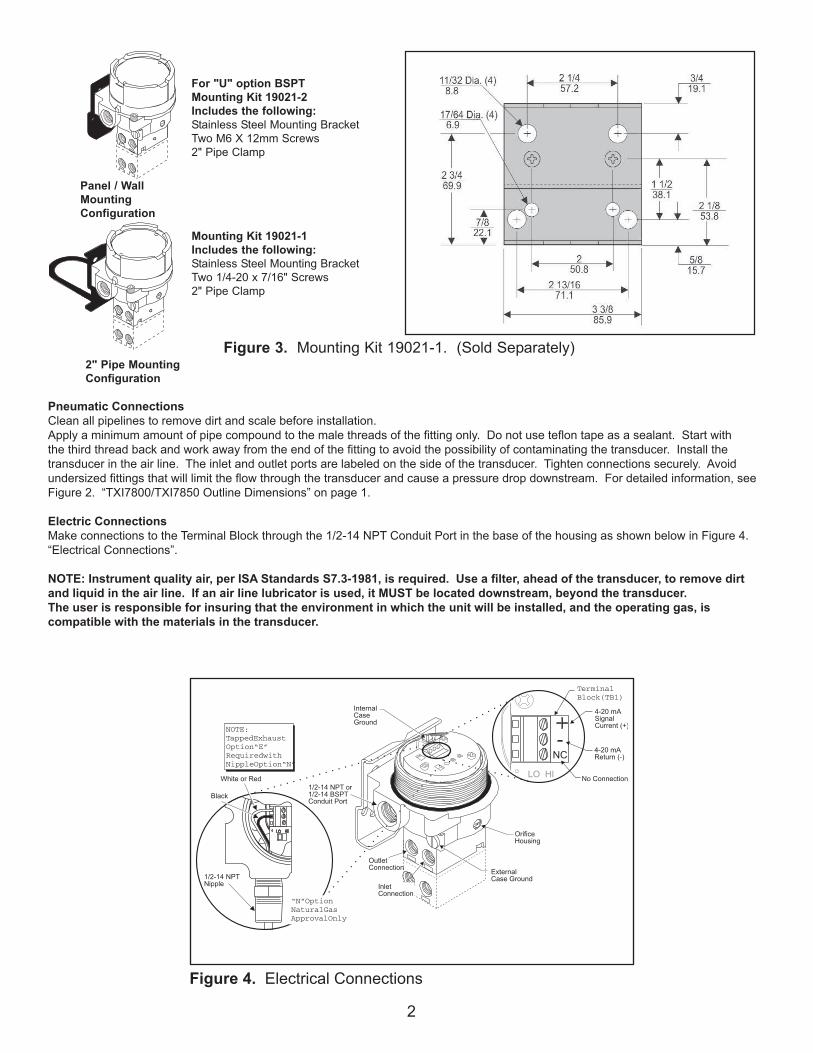
For "U" option BSPT
Mounting Kit 19021-2
Includes the following:
Stainless Steel Mounting Bracket
Two M6 X 12mm Screws
2" Pipe Clamp
Mounting Kit 19021-1
Includes the following:
Stainless Steel Mounting Bracket
Two 1/4-20 x 7/16" Screws
2" Pipe Clamp
Figure 3. Mounting Kit 19021-1. (Sold Separately)
Panel / Wall
Mounting
Configuration
2" Pipe Mounting
Configuration
Pneumatic Connections
Clean all pipelines to remove dirt and scale before installation.
Apply a minimum amount of pipe compound to the male threads of the fitting only. Do not use teflon tape as a sealant. Start with the third
thread back and work away from the end of the fitting to avoid the possibility of contaminating the transducer. Install the transducer in the air
line. The inlet and outlet ports are labeled on the side of the transducer. Tighten connections securely. Avoid undersized fittings that will limit
the flow through the transducer and cause a pressure drop downstream. For detailed information, see Figure 2. “TXI7800/TXI7850 Outline
Dimensions” on page 1.
Electric Connections
Make connections to the Terminal Block through the 1/2-14 NPT Conduit Port in the base of the housing as shown below in Figure 4.
“Electrical Connections”.
Wiring in Hazardous Areas
Wiring in hazardous areas should be performed in
accordance with T_ _able 1. and any local codes
that apply.
NOTE: Instrument quality air, per ISA Standards S7.3-1981, is required. Use a filter, ahead of the transducer, to remove dirt and
liquid in the air line. If an air line lubricator is used, it MUST be located downstream, beyond the transducer.
The user is responsible for insuring that the environment in which the unit will be installed, and the operating gas, is compati-
ble with the materials in the transducer.
Figure 4. Electrical Connections.
“N”Option
NaturalGas
ApprovalOnly
NOTE:
TappedExhaust
Option“E”
Requiredwith
NippleOption“N”
Terminal
Block(TB1)
Table1. Hazardous Location Wiring Practices
Country Agency Code
U.S. FM ANSI/ISA RP 12.6
ANSI/NFPA70
Canada CSA CEC Part1
Europe ATEX EN 50 039, EN 60079-
14, IEC 60079-14
Australia SAA AS/NZS 3000, AS2381.1
Table 2. Intrinsically Safe Connections
Underwriting Group Drawing Number
FM (Factory Mutual) EC- 18970
CSA (Canadian Standards Assoc.) EC- 18971
ATEX EC- 18972
SAA (Standard Australia Assoc.) EC- 19271
Intrinsically Safe Connections
Refer to the latest revision of the indicated drawing.
Pneumatic ConnectionsClean all pipelines to remove dirt and scale before installation.Apply a minimum amount of pipe compound to the male threads of the fitting only. Do not use teflon tape as a sealant. Start with the third thread back and work away from the end of the fitting to avoid the possibility of contaminating the transducer. Install the transducer in the air line. The inlet and outlet ports are labeled on the side of the transducer. Tighten connections securely. Avoid undersized fittings that will limit the flow through the transducer and cause a pressure drop downstream. For detailed information, see Figure 2. “TXI7800/TXI7850 Outline Dimensions” on page 1.
Electric ConnectionsMake connections to the Terminal Block through the 1/2-14 NPT Conduit Port in the base of the housing as shown below in Figure 4. “Electrical Connections”.
NOTE: Instrument quality air, per ISA Standards S7.3-1981, is required. Use a filter, ahead of the transducer, to remove dirt and liquid in the air line. If an air line lubricator is used, it MUST be located downstream, beyond the transducer.The user is responsible for insuring that the environment in which the unit will be installed, and the operating gas, is compatible with the materials in the transducer.
Figure 4. Electrical Connections
“N”OptionNaturalGasApprovalOnly
NOTE:TappedExhaustOption“E”RequiredwithNippleOption“N”
TerminalBlock(TB1)

3
3
CALIBRATIONS / ADJUSTMENTS
Equipment Required for Calibration:
• Pneumatic Supply capable of delivering up to 150 psig.
• Current Supply capable of delivering up to 30 mA.
• Pressure Gage capable of a digital readout up to 50 psig with an accuracy of .1%.
• Digital Volt Meter capable of a readout up to 30 mA with an accuracy of .02%.
FULL RANGE OPERATION
Lo/Hi Span Adjustment
Set the Lo/Hi Span switch to the required position for needed output and supplied MA input. For more detail information, see Figure 6.
“TXI17800/TXI7850 Calibration Configuration”.
Forward Acting Mode Adjustment
Set Fwd/Rev Mode switch to Forward position.
Forward Acting Calibration
1. Apply the minimum input signal to the Terminal Block and adjust the Zero screw for minimum output presure.
2. Apply the maximum input signal to the Terminal Block and adjust the Span screw for maximum output pressure.
3. Repeat steps 1-2 until the desired output range is obtained.
Reverse Acting Mode Adjustment
Set Fwd/Rev Mode switch to the Reverse position
Reverse Acting Calibration
1. Apply the maximum input signal to the Terminal Block and adjust the Zero screw for minimum output pressure.
2. Apply the minimum input signal to the Terminal Block and adjust the Span screw for maximum output pressure.
3.Repeat steps 1-2 until the desired output range is obtained.
SPLIT RANGE OPERATION
Lo/Hi Span Adjustment
Set the Lo/Hi Span switch to the required position for needed output and supplied MA input. For more detail information, see
Figure 6 “TXI7800/TXI7850 Calibration Configuration”.
Forward Acting Mode Adjustment
Set Fwd/Rev Mode switch to Forward position.
Forward Acting Calibration
1. Apply the minimum input signal to the Terminal Block and adjust the Zero screw for minimum output presure.
2. Apply the maximum input signal to the Terminal Block and adjust the Span screw for maximum output pressure.
3. Repeat steps 1-2 until the desired output range is obtained.
Reverse Acting Mode Adjustment
Set Fwd/Rev Mode switch to the Reverse position
Reverse Acting Calibration
1. Apply the maximum input signal to the Terminal Block and adjust the Zero screw for minimum output pressure.
2. Apply the minimum input signal to the Terminal Block and adjust the Span screw for maximum output pressure.
3. Repeat steps 1-2 until the desired output range is obtained.
Additional Adjustments
Damping Adjustment
The Damping Adjustment is used so that the transducer can be tuned for optimum response and stability in a particular application.
For best performance start Damping Adjustment at maximum adjustment (fully clockwise). Gradually turn counterclockwise until
slight oscillation occurs and then turn back clockwise until oscillation is minimized. Turn damping adjustment clockwise to increase damping
function.
ATEX Directive- Special Conditions for Sale
The enclosure is manufactured from aluminum alloy. In rare cases, ignition sources due to impact and friction sparks could occur. This shall
be considered when the equipment is installed in locations that specifically require Group II, category 1G equipment.
“TXI
mA

4
LEGAL NOTICE:
The information set forth in the foregoing Installation, Operation and Maintenance Instructions shall not be modified or amend-
ed in any respect without prior written consent of Fairchild Industrial Products Company. In addition, the information set forth
herein shall be furnished with each product sold incorporating Fairchild's unit as a component thereof.
IS-500TXI78
REV 08/06
Litho in USA
HAZARDOUS AREA SPECIFICATIONS
ATEX Directive Nameplates
Table 1. Trouble-Shooting
Problem Solution (check)
No Output Supply Pressure
Clogged Orifice
Leakage Connections
Low or Improper Zero and Span Adjust
Span Adjust Supply Pressure Low
Output Leakage
Erratic Operation DC Signal
Loose Wires or Connections
Liquid in Air Supply
WARNING:
Failure of Transducer could result in output pressure increasing to supply
pressure possibly causing personal injury or damage to equipment.
Figure 6.
TXI7800/TXI7850 Calibration Configuration
0-30 0-2 0-200 HI
0-60 0-4 0-400 HI
0-120 0-8 0-800 HI
Input Output
psig BAR (kPa)
4-20 mA, 0-5, 1-5,0-10 & 1-9 VDC
SpanPosition
0-15 0-1 0-100 LO15-30 1-2 100-200 LO
0-30 0-2 0-200 LO30-60 2-4 200-400 LO
0-60 0-4 0-400 LO60-120 4-8 400-800 LO
Input Output
4-20 mA, 0-5, 1-5,0-10 & 1-9 VDC
Split Range Output.
psig BAR (kPa)
1
1 1 1
1
1 1
1 1
1
1 1 1
1
1 1
1 1
1
SpanPosition
Extended
Range
Units
Standard
Range
Unit
Standard Range Unit
Extended Range Unit
Service Kits for TXI7800/TXI7850
Series Ranges
TEXI/TAXI 3-15 psig, [0.2-1.0 Bar], (20-100 Kpa)
Kit part no. 19268-1 3-27 psig, [0.2-1.8 Bar], (20-180 Kpa)
6-30 psig, [0.4-2.0 Bar], (40-200 Kpa)
TCXI/TFX 3-15 psig, [0.2-1.0 Bar], (20-100 Kpa)
Kit part no. 19268-2 3-27 psig, [0.2-1.8 Bar], (20-180 Kpa)
6-30 psig, [0.4-2.0 Bar], (40-200 Kpa)
T*XI 0-30 psig, [0.0-2.0 Bar], (0-200 Kpa)
Kit part no. 19268-14
T*XI 0-60 psig, [0.0-4.0 Bar], (0-400 Kpa)
Kit part no. 19268-15
T*XI 0-120 psig, [0.0-8.0 Bar], (0-800 Kpa)
Kit part no. 19268-16
Figure 5.
Service Kits for TXI7800/TXI7850Series RangesTEXI/TAXIKit part no. 19268-1
3-15 psig, [0.2-1.0 Bar], (20-100 Kpa)3-27 psig, [0.2-1-8 Bar], (20-180 Kpa)6-30 psig, [0.4-2.0 Bar], (40-200 Kpa)
TCXI/TFXKit part no. 19268-2
3-15 psig, [0.2-1.0 Bar], (20-100 Kpa)3-27 psig, [0.2-1-8 Bar], (20-180 Kpa)6-30 psig, [0.4-2.0 Bar], (40-200 Kpa)
T*XIKit part no. 19268-14
0-30 psig, [0.0-2.0 Bar], (0-200 Kpa)
T*XIKit part no. 19268-15
0-60 psig, [0.0-4.0 Bar], (0-400 Kpa)
T*XIKit part no. 19268-16
0-120 psig [0.0-8.0 Bar] (0-800 Kpa)
Figure 5

5
LEGAL NOTICE:
The information set forth in the foregoing Installation, Operation and Maintenance Instructions shall not be modified or amend-
ed in any respect without prior written consent of Fairchild Industrial Products Company. In addition, the information set forth
herein shall be furnished with each product sold incorporating Fairchild's unit as a component thereof.
IS-500TXI78
REV 08/06
Litho in USA
HAZARDOUS AREA SPECIFICATIONS
ATEX Directive Nameplates
Table 1. Trouble-Shooting
Problem Solution (check)
No Output Supply Pressure
Clogged Orifice
Leakage Connections
Low or Improper Zero and Span Adjust
Span Adjust Supply Pressure Low
Output Leakage
Erratic Operation DC Signal
Loose Wires or Connections
Liquid in Air Supply
WARNING:
Failure of Transducer could result in output pressure increasing to supply
pressure possibly causing personal injury or damage to equipment.
Figure 6.
TXI7800/TXI7850 Calibration Configuration
0-30 0-2 0-200 HI
0-60 0-4 0-400 HI
0-120 0-8 0-800 HI
Input Output
psig BAR (kPa)
4-20 mA, 0-5, 1-5,0-10 & 1-9 VDC
SpanPosition
0-15 0-1 0-100 LO15-30 1-2 100-200 LO
0-30 0-2 0-200 LO30-60 2-4 200-400 LO
0-60 0-4 0-400 LO60-120 4-8 400-800 LO
Input Output
4-20 mA, 0-5, 1-5,0-10 & 1-9 VDC
Split Range Output.
psig BAR (kPa)
1
1 1 1
1
1 1
1 1
1
1 1 1
1
1 1
1 1
1
SpanPosition
Extended
Range
Units
Standard
Range
Unit
Standard Range Unit
Extended Range Unit
Service Kits for TXI7800/TXI7850
Series Ranges
TEXI/TAXI 3-15 psig, [0.2-1.0 Bar], (20-100 Kpa)
Kit part no. 19268-1 3-27 psig, [0.2-1.8 Bar], (20-180 Kpa)
6-30 psig, [0.4-2.0 Bar], (40-200 Kpa)
TCXI/TFX 3-15 psig, [0.2-1.0 Bar], (20-100 Kpa)
Kit part no. 19268-2 3-27 psig, [0.2-1.8 Bar], (20-180 Kpa)
6-30 psig, [0.4-2.0 Bar], (40-200 Kpa)
T*XI 0-30 psig, [0.0-2.0 Bar], (0-200 Kpa)
Kit part no. 19268-14
T*XI 0-60 psig, [0.0-4.0 Bar], (0-400 Kpa)
Kit part no. 19268-15
T*XI 0-120 psig, [0.0-8.0 Bar], (0-800 Kpa)
Kit part no. 19268-16
Figure 5.
Hazardous Location Installation: Warnings and Special Conditions for Use and InstallationThe enclosure is manufactured from aluminum alloy. In rare cases, ignition sources due to impact and friction sparks could occur. This shallbe considered when the equipment is installed in locations that specifically require Group II, category 1G or Class I, Division 1 equipment.
•Ex ia IIB T4 Ga Ex iaD 20 T90ºC Da SIRA 11ATEX2161X II 1 GD (Ta -40ºC to +80ºC) SYST DWG ED-18972 Ui=28V Ii=100mA Pi=0.7W Ci=0 Li=0
0518
CATALOG NO. TEXI78 -4 INPUT 4-20mAOUTPUTSUPPLY MAX.SUPPLY MIN. OVER MAX. OUTPUTMAXIMUM OPERATING VOLTAGE 30 VDC
Wiring in Hazardous AreasWiring in hazardous areas should be performed inaccordance with Table 3 & 4, and any local codes that apply.
Table 2 - Hazardous Location Wiring PracticesCountry Agency Code
U.S. FM ANSI/ISA RP 12.6ANSI/NFPA70
Canada CSA CEC Part1
Europe ATEX EN 50 0392 EN 60079-14,IEC 60079-14
Global IECEx IEC 60079-14
Table 3 - Intrinsically Safe ConnectionsUnderwriting Group Drawing Number
FM (Factory Mutual) EC-18970
CSA (Canadian Standards Assoc.) EC-18971
ATEX EC-18972
CSA installations for Class I, Division 1 locations with Group D gases as the Supply Pressure media must be installed with either the tapped exhaust option, or the customer must provide adequate purging of the classified area based on the bleed rate and the number of units operating. The bleed rate provided in the table for units is a maximum set point of 30 PSIG output regardless of supply pres-sure up to 125 PSIG maximum.
The information set forth in the foregoing Installation, Operation and Maintenance Instructions shall not be modified or amended in any respect without prior written consent of Fairchild Industrial Products Company. In addition, the information set forth herein shall be furnished with each product sold incorporating Fairchild's unit as a component thereof.
LEGAL NOTICE:
Table 4 - Max Air ConsumptionAir Consumption Set Point Units
30 PSIG[2.0] [BAR](200) (kPa)
SCFH/(m3/Hr) 13.5/(0.38)
6
FAIRCHILD TXI7800/TXI7850
EXPLOSION-PROOF I/P TRANSDUCERS
Installation,Operation and Maintenance Instructions
MAINTENANCE
To clean the Orifice, use the following procedure:
1. Shut off the valve that is supplying air to transducer. It is not necessary to remove the Transducer from the air line.
2. Remove the Orifice Assembly from the unit. For more detailed information see View A.
3. Clean with alcohol and dry with compressed air.
4. Lubricate O-Rings on Orifice Assembly (4) with silicone grease or equivalent lubricant before reassembling.
NOTES:
Parts must be completely dry before reassembling.If the standard maintenance procedure does not correct the trouble, a service
kit containing a replacement diaphragm and orifice assembly is available, see Figure 5.
The Model TXI7800/TXI7850 can be mounted directly onto a flat surface using the two tapped mounting holes in the mounting
face of the housing. For more information, see Figure 2.
TXI7800/TXI7850, Installation with the "N" Option.
NOTE: For Hazardous Location in Potentially Explosive Atmosphere Installations
1. Tapped exhaust required for installation in Class 1, Division 2/Zone 2 (European Union) classified locations with
group D/Group IIA (European Union) gases such as Natural Gas and Methane-Industrial as the pressure supply medium.
2. The explosion-proof pipe nipple seal (N option) supplied with this unit is an integral component of the design safety
of this version and must not be removed. Use caution to avoid marring the threads on the pipe nipple which voids the
explosion-proof integrity of the device.
3. Gases used as the pressure supply medium in hazardous location applications must be compatible with the elas-
tomer indicated in Materials of Construction.
A mounting Kit is available to mount the TXI7800/TXI7850 on a flat surface or on a 2" pipe. For more information, see Figure 3.
INSTALLATION
Figure 2. TXI7800/TXI7850 Outline Dimensions.
Materials of Construction
Body and Housing . Cromate Treated
Aluminum
Orifice . . . . . . . . . . Aluminum
and Sapphire
Trim . . . . . . . . . . . . Stainless Steel, Brass
and Zinc Plated Steel
Sintered Elements . Stainless Steel
Elastomers . . . . . . .Nitrile
Finish . . . . . . . . . . . Epoxy Powder Coating
NOTE: Unused IN and OUT Ports are plugged.
Standard Range Unit
Extended Range Unit
GENERAL INFORMATION
The Model TXI7800/TXI7850 Explosion-Proof I/P Transducer transmits a pneumatic signal which is linearly proportional to a DC
input signal from electronic control devices. The Transducer uses low powered microelectronics and pressure feedback control
to provide a stable, accurate pneumatic output for the operation of valve actuators.
Abbildung 2.
Figure 2.
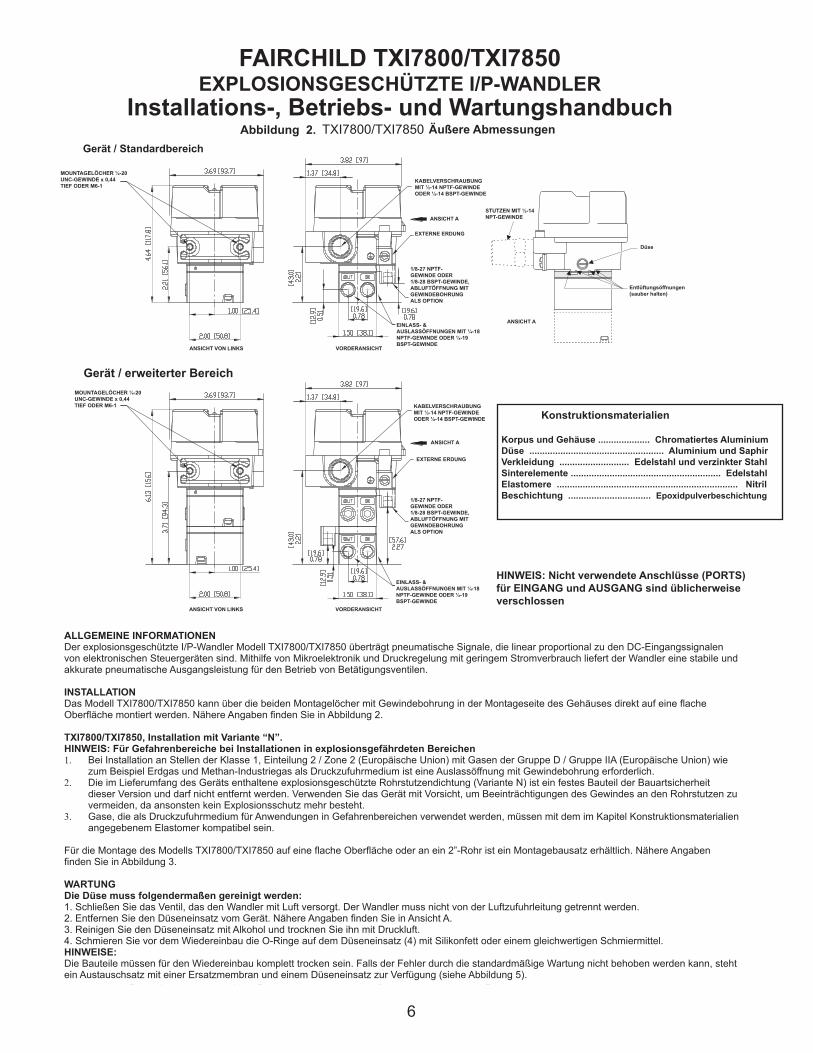
FAIRCHILD TXI7800/TXI7850 EXPLOSIONSGESCHÜTZTE I/P-WANDLER
Installations-, Betriebs- und Wartungshandbuch Äußere Abmessungen
Gerät / Standardbereich
MOUNTAGELÖCHER ¼-20 UNC-GEWINDE x 0,44 TIEF ODER M6-1
ANSICHT VON LINKS
KABELVERSCHRAUBUNG MIT ½-14 NPTF-GEWINDE ODER ½-14 BSPT-GEWINDE
EXTERNE ERDUNG
1/8-27 NPTF-GEWINDE ODER 1/8-28 BSPT-GEWINDE, ABLUFTÖFFNUNG MIT GEWINDEBOHRUNG ALS OPTION
EINLASS- & AUSLASSÖFFNUNGEN MIT ¼-18 NPTF-GEWINDE ODER ¼-19 BSPT-GEWINDE
STUTZEN MIT ½-14 NPT-GEWINDE
Entlüftungsöffnungen (sauber halten)
Gerät / erweiterter Bereich
Korpus und Gehäuse .................... Chromatiertes AluminiumDüse .................................................... Aluminium und SaphirVerkleidung ........................... Edelstahl und verzinkter Stahl Sinterelemente .......................................................... EdelstahlElastomere ...................................................................... NitrilBeschichtung ................................ Epoxidpulverbeschichtung
Konstruktionsmaterialien
HINWEIS: Nicht verwendete Anschlüsse (PORTS) für EINGANG und AUSGANG sind üblicherweise verschlossen
ALLGEMEINE INFORMATIONENDer explosionsgeschützte I/P-Wandler Modell TXI7800/TXI7850 überträgt pneumatische Signale, die linear proportional zu den DC-Eingangssignalen von elektronischen Steuergeräten sind. Mithilfe von Mikroelektronik und Druckregelung mit geringem Stromverbrauch liefert der Wandler eine stabile und akkurate pneumatische Ausgangsleistung für den Betrieb von Betätigungsventilen.
INSTALLATIONDas Modell TXI7800/TXI7850 kann über die beiden Montagelöcher mit Gewindebohrung in der Montageseite des Gehäuses direkt auf eine flache Oberfläche montiert werden. Nähere Angaben finden Sie in Abbildung 2.
TXI7800/TXI7850, Installation mit Variante “N”.HINWEIS: Für Gefahrenbereiche bei Installationen in explosionsgefährdeten Bereichen1. Bei Installation an Stellen der Klasse 1, Einteilung 2 / Zone 2 (Europäische Union) mit Gasen der Gruppe D / Gruppe IIA (Europäische Union) wie
zum Beispiel Erdgas und Methan-Industriegas als Druckzufuhrmedium ist eine Auslassöffnung mit Gewindebohrung erforderlich.2. Die im Lieferumfang des Geräts enthaltene explosionsgeschützte Rohrstutzendichtung (Variante N) ist ein festes Bauteil der Bauartsicherheit
dieser Version und darf nicht entfernt werden. Verwenden Sie das Gerät mit Vorsicht, um Beeinträchtigungen des Gewindes an den Rohrstutzen zu vermeiden, da ansonsten kein Explosionsschutz mehr besteht.
3. Gase, die als Druckzufuhrmedium für Anwendungen in Gefahrenbereichen verwendet werden, müssen mit dem im Kapitel Konstruktionsmaterialien angegebenem Elastomer kompatibel sein.
Für die Montage des Modells TXI7800/TXI7850 auf eine flache Oberfläche oder an ein 2”-Rohr ist ein Montagebausatz erhältlich. Nähere Angaben finden Sie in Abbildung 3.
WARTUNG Die Düse muss folgendermaßen gereinigt werden:1. Schließen Sie das Ventil, das den Wandler mit Luft versorgt. Der Wandler muss nicht von der Luftzufuhrleitung getrennt werden.2. Entfernen Sie den Düseneinsatz vom Gerät. Nähere Angaben finden Sie in Ansicht A.3. Reinigen Sie den Düseneinsatz mit Alkohol und trocknen Sie ihn mit Druckluft.4. Schmieren Sie vor dem Wiedereinbau die O-Ringe auf dem Düseneinsatz (4) mit Silikonfett oder einem gleichwertigen Schmiermittel.HINWEISE: Die Bauteile müssen für den Wiedereinbau komplett trocken sein. Falls der Fehler durch die standardmäßige Wartung nicht behoben werden kann, steht ein Austauschsatz mit einer Ersatzmembran und einem Düseneinsatz zur Verfügung (siehe Abbildung 5).
Düse
VORDERANSICHT
ANSICHT A
ANSICHT A
MOUNTAGELÖCHER ¼-20 UNC-GEWINDE x 0,44 TIEF ODER M6-1
ANSICHT VON LINKS VORDERANSICHT
KABELVERSCHRAUBUNG MIT ½-14 NPTF-GEWINDE ODER ½-14 BSPT-GEWINDE
ANSICHT A
EXTERNE ERDUNG
1/8-27 NPTF-GEWINDE ODER 1/8-28 BSPT-GEWINDE, ABLUFTÖFFNUNG MIT GEWINDEBOHRUNG ALS OPTION
EINLASS- & AUSLASSÖFFNUNGEN MIT ¼-18 NPTF-GEWINDE ODER ¼-19 BSPT-GEWINDE
72
For "U" option BSPT
Mounting Kit 19021-2
Includes the following:
Stainless Steel Mounting Bracket
Two M6 X 12mm Screws
2" Pipe Clamp
Mounting Kit 19021-1
Includes the following:
Stainless Steel Mounting Bracket
Two 1/4-20 x 7/16" Screws
2" Pipe Clamp
Figure 3. Mounting Kit 19021-1. (Sold Separately)
Panel / Wall
Mounting
Configuration
2" Pipe Mounting
Configuration
Pneumatic Connections
Clean all pipelines to remove dirt and scale before installation.
Apply a minimum amount of pipe compound to the male threads of the fitting only. Do not use teflon tape as a sealant. Start with the third
thread back and work away from the end of the fitting to avoid the possibility of contaminating the transducer. Install the transducer in the air
line. The inlet and outlet ports are labeled on the side of the transducer. Tighten connections securely. Avoid undersized fittings that will limit
the flow through the transducer and cause a pressure drop downstream. For detailed information, see Figure 2. “TXI7800/TXI7850 Outline
Dimensions” on page 1.
Electric Connections
Make connections to the Terminal Block through the 1/2-14 NPT Conduit Port in the base of the housing as shown below in Figure 4.
“Electrical Connections”.
Wiring in Hazardous Areas
Wiring in hazardous areas should be performed in
accordance with T_ _able 1. and any local codes
that apply.
NOTE: Instrument quality air, per ISA Standards S7.3-1981, is required. Use a filter, ahead of the transducer, to remove dirt and
liquid in the air line. If an air line lubricator is used, it MUST be located downstream, beyond the transducer.
The user is responsible for insuring that the environment in which the unit will be installed, and the operating gas, is compati-
ble with the materials in the transducer.
Figure 4. Electrical Connections.
“N”Option
NaturalGas
ApprovalOnly
NOTE:
TappedExhaust
Option“E”
Requiredwith
NippleOption“N”
Terminal
Block(TB1)
Table1. Hazardous Location Wiring Practices
Country Agency Code
U.S. FM ANSI/ISA RP 12.6
ANSI/NFPA70
Canada CSA CEC Part1
Europe ATEX EN 50 039, EN 60079-
14, IEC 60079-14
Australia SAA AS/NZS 3000, AS2381.1
Table 2. Intrinsically Safe Connections
Underwriting Group Drawing Number
FM (Factory Mutual) EC- 18970
CSA (Canadian Standards Assoc.) EC- 18971
ATEX EC- 18972
SAA (Standard Australia Assoc.) EC- 19271
Intrinsically Safe Connections
Refer to the latest revision of the indicated drawing.
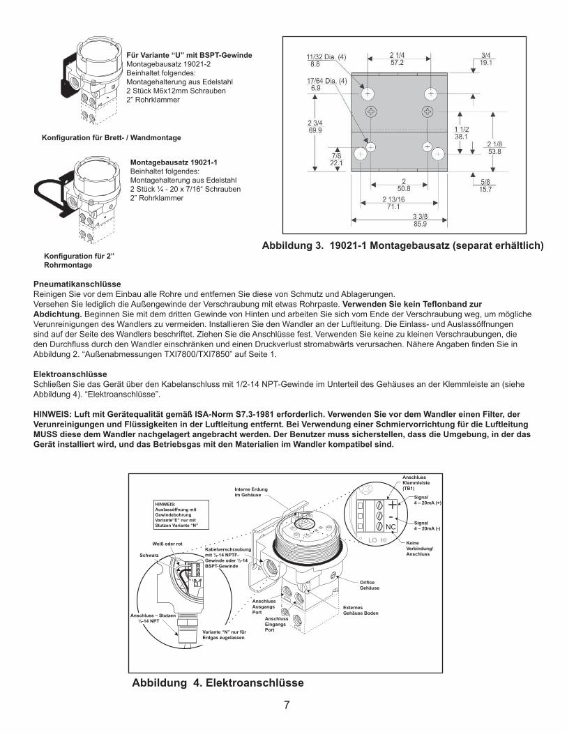
PneumatikanschlüsseReinigen Sie vor dem Einbau alle Rohre und entfernen Sie diese von Schmutz und Ablagerungen.Versehen Sie lediglich die Außengewinde der Verschraubung mit etwas Rohrpaste. Verwenden Sie kein Teflonband zur Abdichtung. Beginnen Sie mit dem dritten Gewinde von Hinten und arbeiten Sie sich vom Ende der Verschraubung weg, um mögliche Verunreinigungen des Wandlers zu vermeiden. Installieren Sie den Wandler an der Luftleitung. Die Einlass- und Auslassöffnungen sind auf der Seite des Wandlers beschriftet. Ziehen Sie die Anschlüsse fest. Verwenden Sie keine zu kleinen Verschraubungen, die den Durchfluss durch den Wandler einschränken und einen Druckverlust stromabwärts verursachen. Nähere Angaben finden Sie in Abbildung 2. “Außenabmessungen TXI7800/TXI7850” auf Seite 1.
ElektroanschlüsseSchließen Sie das Gerät über den Kabelanschluss mit 1/2-14 NPT-Gewinde im Unterteil des Gehäuses an der Klemmleiste an (siehe Abbildung 4). “Elektroanschlüsse”.
HINWEIS: Luft mit Gerätequalität gemäß ISA-Norm S7.3-1981 erforderlich. Verwenden Sie vor dem Wandler einen Filter, der Verunreinigungen und Flüssigkeiten in der Luftleitung entfernt. Bei Verwendung einer Schmiervorrichtung für die Luftleitung MUSS diese dem Wandler nachgelagert angebracht werden. Der Benutzer muss sicherstellen, dass die Umgebung, in der das Gerät installiert wird, und das Betriebsgas mit den Materialien im Wandler kompatibel sind.
Abbildung 4. Elektroanschlüsse
“N”OptionNaturalGasApprovalOnly
NOTE:TappedExhaustOption“E”RequiredwithNippleOption“N”
TerminalBlock(TB1)
Abbildung 3. 19021-1 Montagebausatz (separat erhältlich)
Konfiguration für Brett- / Wandmontage
Für Variante “U” mit BSPT-GewindeMontagebausatz 19021-2Beinhaltet folgendes:Montagehalterung aus Edelstahl2 Stück M6x12mm Schrauben2” Rohrklammer
Montagebausatz 19021-1Beinhaltet folgendes:Montagehalterung aus Edelstahl2 Stück ¼ - 20 x 7/16“ Schrauben2” Rohrklammer
Konfiguration für 2” Rohrmontage
HINWEIS: Auslassöffnung mit Gewindebohrung Variante”E” nur mit Stutzen Variante “N”
Weiß oder rot
Schwarz
Variante “N” nur für Erdgas zugelassen
Interne Erdung im Gehäuse
Anschluss Ausgangs Port
Anschluss Klemmleiste (TB1)
Signal4 – 20mA (+)
Signal4 – 20mA (-)
Keine Verbindung/Anschluss
Orifice Gehäuse
Anschluss – Stutzen ½-14 NPT
Kabelverschraubung mit ½-14 NPTF-Gewinde oder ½-14 BSPT-Gewinde
Anschluss Eingangs Port
ExternesGehäuse Boden

8
KALIBRIERUNG / ANSCHLÜSSE
Für die Kalibrierung erforderliche Ausrüstung:• Pneumatikanschluss, ausgelegt für bis zu 150 psig • Stromanschluss, ausgelegt für bis zu 30 mA.• Druckmessgerät, ausgelegt für die digitale Anzeige von bis zu 50 psig mit einer Genauigkeit von 0,1%.• Digitaler Spannungsmesser, ausgelegt für die digitale Anzeige von bis zu 30 mA mit einer Genauigkeit von 0,02%.
FULLRANGE-BETRIEBEinstellen der niedrigen/hohen SpannweiteStellen Sie den Schalter Niedrige/Hohe SPAN auf die gewünschte Position für die benötigte Ausgangsleistung sowie die dazu gehörigen Eingangsparameter ein. Nähere Angaben finden Sie in Abbildung 6.“Kalibrierkonfiguration TXI7800/TXI7850”.
Einstellen des VorwärtsmodusStellen Sie den Schalter Vorwärts-/Rückwärtsmodus auf Vorwärts.
Vorwärts-Kalibrierung1. Schließen Sie das Mindesteingangssignal an der Klemmleiste an und stellen Sie die Nullpunktschraube auf Mindestausgangsdruck ein.2. Schließen Sie das maximale Eingangssignal an der Klemmleiste an und stellen Sie die Spannweitenschraube auf maximalen
Ausgangsdruck ein.3. Wiederholen Sie die Schritte 1-2, bis der Bereich der gewünschten Ausgangsleistung erreicht ist.
Einstellen des RückwärtsmodusStellen Sie den Schalter Vorwärts-/Rückwärtsmodus auf Rückwärts.
Rückwärts-Kalibrierung1. Schließen Sie das maximale Eingangssignal an der Klemmleiste an und stellen Sie die Nullpunktschraube auf Mindestausgangsdruck ein.2. Schließen Sie das Mindesteingangssignal an der Klemmleiste an und stellen Sie die Spannweitenschraube auf maximalen Ausgangsdruck
ein.3. Wiederholen Sie die Schritte 1-2, bis der Bereich der gewünschten Ausgangsleistung erreicht ist.
SPLITRANGE-BETRIEBEinstellen der niedrigen/hohen SpannweiteStellen Sie den Schalter Niedrige/Hohe SPAN auf die gewünschte Position für die benötigte Ausgangsleistung sowie die dazu gehörigen Eingangsparameter ein. Nähere Angaben finden Sie in Abbildung 6.
Einstellen des VorwärtsmodusStellen Sie den Schalter Vorwärts-/Rückwärtsmodus auf Vorwärts.
Vorwärts-Kalibrierung1. Schließen Sie das Mindesteingangssignal an der Klemmleiste an und stellen Sie die Nullpunktschraube auf Mindestausgangsdruck ein.2. Schließen Sie das maximale Eingangssignal an der Klemmleiste an und stellen Sie die Spannweitenschraube auf maximalen
Ausgangsdruck ein.3. Wiederholen Sie die Schritte 1-2, bis der Bereich der gewünschten Ausgangsleistung erreicht ist.
Einstellen des RückwärtsmodusStellen Sie den Schalter Vorwärts-/Rückwärtsmodus auf Rückwärts.
Rückwärts-Kalibrierung1. Schließen Sie das maximale Eingangssignal an der Klemmleiste an und stellen Sie die Nullpunktschraube auf Mindestausgangsdruck ein.2. Schließen Sie das Mindesteingangssignal an der Klemmleiste an und stellen Sie die Spannweitenschraube auf maximalen Ausgangsdruck
ein.3. Wiederholen Sie die Schritte 1-2, bis der Bereich der gewünschten Ausgangsleistung erreicht ist.
Zusätzliche EinstellungenEinstellen der DämpfungMit dem Einstellen der Dämpfung kann der Wandler auf ein optimales Ansprechverhalten und Stabilität in bestimmten Anwendungen abgestimmt werden.Um maximale Leistung zu erzielen, stellen Sie die Dämpfung zunächst auf das Maximum ein (volle Drehung im Uhrzeigersinn). Drehen Sie den Schalter schrittweise entgegen dem Uhrzeigersinn, bis eine leichte Oszillation auftritt, und drehen Sie den Schalter dann im Uhrzeigersinn wieder zurück, bis die Oszillation auf ein Minimum reduziert ist. Drehen Sie den Schalter zum Einstellen der Dämpfung im Uhrzeigersinn, um die Dämpfungsfunktion zu erhöhen.
9
LEGAL NOTICE:
The information set forth in the foregoing Installation, Operation and Maintenance Instructions shall not be modified or amend-
ed in any respect without prior written consent of Fairchild Industrial Products Company. In addition, the information set forth
herein shall be furnished with each product sold incorporating Fairchild's unit as a component thereof.
IS-500TXI78
REV 08/06
Litho in USA
HAZARDOUS AREA SPECIFICATIONS
ATEX Directive Nameplates
Table 1. Trouble-Shooting
Problem Solution (check)
No Output Supply Pressure
Clogged Orifice
Leakage Connections
Low or Improper Zero and Span Adjust
Span Adjust Supply Pressure Low
Output Leakage
Erratic Operation DC Signal
Loose Wires or Connections
Liquid in Air Supply
WARNING:
Failure of Transducer could result in output pressure increasing to supply
pressure possibly causing personal injury or damage to equipment.
Figure 6.
TXI7800/TXI7850 Calibration Configuration
0-30 0-2 0-200 HI
0-60 0-4 0-400 HI
0-120 0-8 0-800 HI
Input Output
psig BAR (kPa)
4-20 mA, 0-5, 1-5,0-10 & 1-9 VDC
SpanPosition
0-15 0-1 0-100 LO15-30 1-2 100-200 LO
0-30 0-2 0-200 LO30-60 2-4 200-400 LO
0-60 0-4 0-400 LO60-120 4-8 400-800 LO
Input Output
4-20 mA, 0-5, 1-5,0-10 & 1-9 VDC
Split Range Output.
psig BAR (kPa)
1
1 1 1
1
1 1
1 1
1
1 1 1
1
1 1
1 1
1
SpanPosition
Extended
Range
Units
Standard
Range
Unit
Standard Range Unit
Extended Range Unit
Service Kits for TXI7800/TXI7850
Series Ranges
TEXI/TAXI 3-15 psig, [0.2-1.0 Bar], (20-100 Kpa)
Kit part no. 19268-1 3-27 psig, [0.2-1.8 Bar], (20-180 Kpa)
6-30 psig, [0.4-2.0 Bar], (40-200 Kpa)
TCXI/TFX 3-15 psig, [0.2-1.0 Bar], (20-100 Kpa)
Kit part no. 19268-2 3-27 psig, [0.2-1.8 Bar], (20-180 Kpa)
6-30 psig, [0.4-2.0 Bar], (40-200 Kpa)
T*XI 0-30 psig, [0.0-2.0 Bar], (0-200 Kpa)
Kit part no. 19268-14
T*XI 0-60 psig, [0.0-4.0 Bar], (0-400 Kpa)
Kit part no. 19268-15
T*XI 0-120 psig, [0.0-8.0 Bar], (0-800 Kpa)
Kit part no. 19268-16
Figure 5.
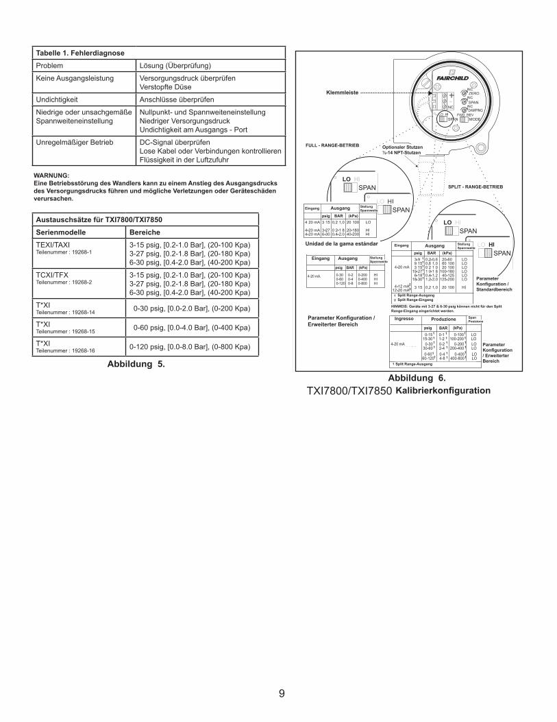
Abbildung 5.Abbildung 6.
Tabelle 1. FehlerdiagnoseProblem Lösung (Überprüfung)
Keine Ausgangsleistung Versorgungsdruck überprüfenVerstopfte Düse
Undichtigkeit Anschlüsse überprüfen
Niedrige oder unsachgemäßeSpannweiteneinstellung
Nullpunkt- und SpannweiteneinstellungNiedriger VersorgungsdruckUndichtigkeit am Ausgangs - Port
Unregelmäßiger Betrieb DC-Signal überprüfenLose Kabel oder Verbindungen kontrollierenFlüssigkeit in der Luftzufuhr
WARNUNG:Eine Betriebsstörung des Wandlers kann zu einem Anstieg des Ausgangsdrucks des Versorgungsdrucks führen und mögliche Verletzungen oder Geräteschäden verursachen.
FULL - RANGE-BETRIEB
SPLIT - RANGE-BETRIEB
Unidad de la gama estándar
Parameter Konfiguration / Standardbereich
Parameter Konfiguration / Erweiterter Bereich
Parameter Konfiguration / Erweiterter Bereich
Kalibrierkonfiguration
Eingang
HINWEIS: Geräte mit 3-27 & 6-30 psig können nicht für den Split Range-Eingang eingerichtet werden.
Klemmleiste
Optionaler Stutzen ½-14 NPT-Stutzen
Eingang Ausgang
Split Range-Ausgang
Split Range-AusgangSplit Range-Eingang
Eingang
Ingresso
Ausgang
Ausgang
Produzione
StellungSpannweite
SpanPosizione
StellungSpannweite
StellungSpannweite
Austauschsätze für TXI7800/TXI7850Serienmodelle BereicheTEXI/TAXITeilenummer : 19268-1
3-15 psig, [0.2-1.0 Bar], (20-100 Kpa)3-27 psig, [0.2-1.8 Bar], (20-180 Kpa)6-30 psig, [0.4-2.0 Bar], (40-200 Kpa)
TCXI/TFXTeilenummer : 19268-2
3-15 psig, [0.2-1.0 Bar], (20-100 Kpa)3-27 psig, [0.2-1.8 Bar], (20-180 Kpa)6-30 psig, [0.4-2.0 Bar], (40-200 Kpa)
T*XITeilenummer : 19268-14 0-30 psig, [0.0-2.0 Bar], (0-200 Kpa)
T*XITeilenummer : 19268-15 0-60 psig, [0.0-4.0 Bar], (0-400 Kpa)
T*XITeilenummer : 19268-16 0-120 psig, [0.0-8.0 Bar], (0-800 Kpa)

10
LEGAL NOTICE:
The information set forth in the foregoing Installation, Operation and Maintenance Instructions shall not be modified or amend-
ed in any respect without prior written consent of Fairchild Industrial Products Company. In addition, the information set forth
herein shall be furnished with each product sold incorporating Fairchild's unit as a component thereof.
IS-500TXI78
REV 08/06
Litho in USA
HAZARDOUS AREA SPECIFICATIONS
ATEX Directive Nameplates
Table 1. Trouble-Shooting
Problem Solution (check)
No Output Supply Pressure
Clogged Orifice
Leakage Connections
Low or Improper Zero and Span Adjust
Span Adjust Supply Pressure Low
Output Leakage
Erratic Operation DC Signal
Loose Wires or Connections
Liquid in Air Supply
WARNING:
Failure of Transducer could result in output pressure increasing to supply
pressure possibly causing personal injury or damage to equipment.
Figure 6.
TXI7800/TXI7850 Calibration Configuration
0-30 0-2 0-200 HI
0-60 0-4 0-400 HI
0-120 0-8 0-800 HI
Input Output
psig BAR (kPa)
4-20 mA, 0-5, 1-5,0-10 & 1-9 VDC
SpanPosition
0-15 0-1 0-100 LO15-30 1-2 100-200 LO
0-30 0-2 0-200 LO30-60 2-4 200-400 LO
0-60 0-4 0-400 LO60-120 4-8 400-800 LO
Input Output
4-20 mA, 0-5, 1-5,0-10 & 1-9 VDC
Split Range Output.
psig BAR (kPa)
1
1 1 1
1
1 1
1 1
1
1 1 1
1
1 1
1 1
1
SpanPosition
Extended
Range
Units
Standard
Range
Unit
Standard Range Unit
Extended Range Unit
Service Kits for TXI7800/TXI7850
Series Ranges
TEXI/TAXI 3-15 psig, [0.2-1.0 Bar], (20-100 Kpa)
Kit part no. 19268-1 3-27 psig, [0.2-1.8 Bar], (20-180 Kpa)
6-30 psig, [0.4-2.0 Bar], (40-200 Kpa)
TCXI/TFX 3-15 psig, [0.2-1.0 Bar], (20-100 Kpa)
Kit part no. 19268-2 3-27 psig, [0.2-1.8 Bar], (20-180 Kpa)
6-30 psig, [0.4-2.0 Bar], (40-200 Kpa)
T*XI 0-30 psig, [0.0-2.0 Bar], (0-200 Kpa)
Kit part no. 19268-14
T*XI 0-60 psig, [0.0-4.0 Bar], (0-400 Kpa)
Kit part no. 19268-15
T*XI 0-120 psig, [0.0-8.0 Bar], (0-800 Kpa)
Kit part no. 19268-16
Figure 5.
•Ex ia IIB T4 Ga Ex iaD 20 T90ºC Da SIRA 11ATEX2161X II 1 GD (Ta -40ºC to +80ºC) SYST DWG ED-18972 Ui=28V Ii=100mA Pi=0.7W Ci=0 Li=0
0518
CATALOG NO. TEXI78 -4 INPUT 4-20mAOUTPUTSUPPLY MAX.SUPPLY MIN. OVER MAX. OUTPUTMAXIMUM OPERATING VOLTAGE 30 VDC
Kabelverlegung in gefährdeten/gefährlichen BereichenDie Kabelverlegung in gefährdeten/gefährlichen Bereichen muss gemäß Tabelle 2 (Kabelverlegung in gefährdeten/gefährlichen Bereichen) & Tabelle 3 (Eigensichere Anschlüsse) sowie gemäß den geltenden örtlichen Gesetzen durchgeführt werden.
Tabelle 3 – Eigensichere AnschlüsseKonsortium Zeichnungsnummer
FM (Factory Mutual) EC-18970
CSA (Canadian Standards Assoc.) EC-18971
ATEX EC-18972
Tabelle 2 – Verkabelung in gefährdeten/gefährlichen BereichenLand Behörde Code
U.S. FM ANSI/ISA RP 12.6ANSI/NFPA70
Kanada CSA CEC Part1
Europa ATEX EN 50 0392 EN 60079-14,IEC 60079-14
Weltweit IECEx IEC 60079-14
Tabelle 4 - Max. LuftverbrauchLuftverbrauch Sollwert/Einstellwert Units
30 PSIG
[2.0] [BAR]
(200) (kPa)
SCFH/(m3/Hr) 13.5/(0.38)
SPEZIFIKATIONEN FÜR GEFAHRENBEREICHETypenschilder für ATEX-Anweisungen
Die im vorangehenden Installations-, Betriebs- und Wartungshandbuch dargelegten Angaben dürfen in keinerlei Hinsicht ohne die vorherige schriftliche Zustimmung der Fairchild Industrial Products Company geändert oder ergänzt werden. Außerdem müssen die hinterlegten Angaben zusammen mit jedem verkauften Produkt, die ein Bauteil von Fairchild enthalten, ausgehändigt werden.
RECHTLICHER HINWEIS:
Spezielle Nutzungs- und Installationsbedingungen der AufsichtsbehördeDas Gehäuse ist aus Aluminiumlegierung gefertigt. In seltenen Fällen können aufgrund von Einwirkungen Zündquellen und Reibfunken auftreten. Das muss berücksichtigt werden, wenn das Gerät in Bereichen installiert wird, für die Ausrüstung der Gruppe II, Kategorie 1G oder der Klasse I, Einteilung 1 erforderlich ist.
CSA-Installationen in Bereichen der Klasse I, Einteilung 1 mit Gasen der Gruppe D als Druckversorgungsmedium müssen entweder mit einer Auslassöffnung mit Gewindebohrung installiert werden, oder der Kunde muss eine ausreichende Entlüftung des klassifizierten Bereichs auf Basis der Entlüftungsrate und der Anzahl an betriebenen Geräten bereitstellen. Die in der Tabelle für die Geräte aufgeführte Entlüftungsrate ist ein maximaler Sollwert von 30 PSIG Ausgangsleistung ohne Berücksichtigung des Versorgungsdruck von bis zu max. 125 PSIG.
11
FAIRCHILD TXI7800/TXI7850
EXPLOSION-PROOF I/P TRANSDUCERS
Installation,Operation and Maintenance Instructions
MAINTENANCE
To clean the Orifice, use the following procedure:
1. Shut off the valve that is supplying air to transducer. It is not necessary to remove the Transducer from the air line.
2. Remove the Orifice Assembly from the unit. For more detailed information see View A.
3. Clean with alcohol and dry with compressed air.
4. Lubricate O-Rings on Orifice Assembly (4) with silicone grease or equivalent lubricant before reassembling.
NOTES:
Parts must be completely dry before reassembling.If the standard maintenance procedure does not correct the trouble, a service
kit containing a replacement diaphragm and orifice assembly is available, see Figure 5.
The Model TXI7800/TXI7850 can be mounted directly onto a flat surface using the two tapped mounting holes in the mounting
face of the housing. For more information, see Figure 2.
TXI7800/TXI7850, Installation with the "N" Option.
NOTE: For Hazardous Location in Potentially Explosive Atmosphere Installations
1. Tapped exhaust required for installation in Class 1, Division 2/Zone 2 (European Union) classified locations with
group D/Group IIA (European Union) gases such as Natural Gas and Methane-Industrial as the pressure supply medium.
2. The explosion-proof pipe nipple seal (N option) supplied with this unit is an integral component of the design safety
of this version and must not be removed. Use caution to avoid marring the threads on the pipe nipple which voids the
explosion-proof integrity of the device.
3. Gases used as the pressure supply medium in hazardous location applications must be compatible with the elas-
tomer indicated in Materials of Construction.
A mounting Kit is available to mount the TXI7800/TXI7850 on a flat surface or on a 2" pipe. For more information, see Figure 3.
INSTALLATION
Figure 2. TXI7800/TXI7850 Outline Dimensions.
Materials of Construction
Body and Housing . Cromate Treated
Aluminum
Orifice . . . . . . . . . . Aluminum
and Sapphire
Trim . . . . . . . . . . . . Stainless Steel, Brass
and Zinc Plated Steel
Sintered Elements . Stainless Steel
Elastomers . . . . . . .Nitrile
Finish . . . . . . . . . . . Epoxy Powder Coating
NOTE: Unused IN and OUT Ports are plugged.
Standard Range Unit
Extended Range Unit
GENERAL INFORMATION
The Model TXI7800/TXI7850 Explosion-Proof I/P Transducer transmits a pneumatic signal which is linearly proportional to a DC
input signal from electronic control devices. The Transducer uses low powered microelectronics and pressure feedback control
to provide a stable, accurate pneumatic output for the operation of valve actuators.
Figura 2.
Figure 2.
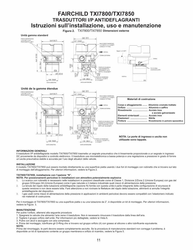
FAIRCHILD TXI7800/TXI7850 TRASDUTTORI I/P ANTIDEFLAGRANTI
Istruzioni sull’installazione, uso e manutenzione Dimensioni esterne
Unità gamma standardFORI DI MONTAGGIO ¼-20 UNC x 0,44 PROFONDITÀ O M6-1
VISTA SINISTRA
RACCORDO INGRESSO ½-14 NPTF O ½-14 BSPTCONDUIT FITTING
VISTA A
TERRA ESTERNA
PORTA DI SCARICO CON RUBINETTO OPZIONALE 1/8-27 NPTF O 1/8-28 BSPT
PORTE DI INGRESSO E USCITA ¼-18 NPTF O ¼-19 BSPT
VISTA ANTERIORE
Nipplo ½-14 NPT
Fori di sfiato(mantenere puliti)
VISTA A
Unité de la gamme étendueFORI DI MONTAGGIO ¼-20 UNC x 0,44 PROFONDITA O M6-1
VISTA SINISTRA
VISTA A
RACCORDO INGRESSO ½-14 NPTF O ½-14 BSPTCONDUIT FITTING
TERRA ESTERNA
PORTA DI SCARICO CON RUBINETTO OPZIONALE (DUE POSIZIONI) 1/8-27 NPTF OR 1/8-28 BSPT
PORTE DI INGRESSO E USCITA ¼-18 NPTF O ¼-19 BSPT
Corpo e alloggiamento ........ Alluminio cromato trattatoOrifizio .................................. Alluminio e zaffiroRivestimento ........................ Acciaio inox e acciaio galvanizzatoElementi sinterizzati ............. Acciaio inoxElastomeri ........................... NitrileFinitura ................................. Rivestimento in polvere epossidica
Materiali di costruzione
NOTA: Le porte di ingresso e uscita non utilizzate sono tappate.
INFORMAZIONI GENERALIIl trasduttore I/P antideflagrante modello TXI7800/TXI7850 trasmette un segnale pneumatico che è linearmente proporzionale a un segnale in ingresso DC proveniente da dispositivi a controllo elettronico. Il trasduttore usa microelettronica a bassa potenza e una regolazione a pressione in grado di fornire un’uscita pneumatica stabile e accurata per l’uso degli attuatori delle valvole.
INSTALLAZIONEIl modello TXI7800/TXI7850 può essere montato direttamente su una superficie piatta usando i due fori di montaggio con rubinetto che si trovano sul lato di montaggio dell’alloggiamento. Per ulteriori informazioni, vedere la Figura 2.
TXI7800/TXI7850, installazione con l’opzione “N”.NOTA: Per posizionamenti pericolosi in installazioni con atmosfera potenzialmente esplosiva1. Lo scarico con rubinetto è necessario nelle installazioni in posizioni classificate come di Classe 1, Divisione 2/Zona 2 (Unione Europea) con gas del
gruppo D/Gruppo IIA (Unione Europea) come il gas naturale e il metano industriale quali mezzi di alimentazione della pressione.2. La tenuta del nipplo della tubazione antideflagrante (opzione N) fornita con questa unità è parte integrante della configurazione di sicurezza di
questa versione e non deve essere tolta. Fare attenzione a non rovinare le filettature del nipplo della tubazione, altrimenti si annulla l’integrità antideflagrante del dispositivo.
3. I gas usati come mezzi di alimentazione della pressione in applicazioni in ambienti pericolosi devono essere compatibili con l’elastomero indicato nei materiali di costruzione.
Per il montaggio di TXI7800/TXI7850 su una superficie piatta o su una tubazione da 2”, è disponibile un kit di montaggio. Per ulteriori informazioni, vedere la Figura 3.
MANUTENZIONE Per pulire l’orifizio, attenersi alla seguente procedura:1. Spegnere la valvola che alimenta l’aria verso il trasduttore. Non è necessario rimuovere il trasduttore dalla linea dell’aria.2. Togliere il gruppo orifizio dall’unità. Per informazioni più dettagliate, vedere la Vista A.3. Pulire con alcol e asciugare con aria compressa.4. Prima del montaggio, lubrificare gli O-Ring che si trovano sul gruppo orifizio (4) con grasso al silicone o altro lubrificante equivalente.NOTE: Prima del rimontaggio, le parti devono essere completamente asciutte. Se la procedura di manutenzione standard non corregge il problema, è disponibile un kit di riparazione contente un gruppo membrana e orifizio di ricambio, vedere la Figura 5.
Orifizio
VISTA ANTERIORE
122
For "U" option BSPT
Mounting Kit 19021-2
Includes the following:
Stainless Steel Mounting Bracket
Two M6 X 12mm Screws
2" Pipe Clamp
Mounting Kit 19021-1
Includes the following:
Stainless Steel Mounting Bracket
Two 1/4-20 x 7/16" Screws
2" Pipe Clamp
Figure 3. Mounting Kit 19021-1. (Sold Separately)
Panel / Wall
Mounting
Configuration
2" Pipe Mounting
Configuration
Pneumatic Connections
Clean all pipelines to remove dirt and scale before installation.
Apply a minimum amount of pipe compound to the male threads of the fitting only. Do not use teflon tape as a sealant. Start with the third
thread back and work away from the end of the fitting to avoid the possibility of contaminating the transducer. Install the transducer in the air
line. The inlet and outlet ports are labeled on the side of the transducer. Tighten connections securely. Avoid undersized fittings that will limit
the flow through the transducer and cause a pressure drop downstream. For detailed information, see Figure 2. “TXI7800/TXI7850 Outline
Dimensions” on page 1.
Electric Connections
Make connections to the Terminal Block through the 1/2-14 NPT Conduit Port in the base of the housing as shown below in Figure 4.
“Electrical Connections”.
Wiring in Hazardous Areas
Wiring in hazardous areas should be performed in
accordance with T_ _able 1. and any local codes
that apply.
NOTE: Instrument quality air, per ISA Standards S7.3-1981, is required. Use a filter, ahead of the transducer, to remove dirt and
liquid in the air line. If an air line lubricator is used, it MUST be located downstream, beyond the transducer.
The user is responsible for insuring that the environment in which the unit will be installed, and the operating gas, is compati-
ble with the materials in the transducer.
Figure 4. Electrical Connections.
“N”Option
NaturalGas
ApprovalOnly
NOTE:
TappedExhaust
Option“E”
Requiredwith
NippleOption“N”
Terminal
Block(TB1)
Table1. Hazardous Location Wiring Practices
Country Agency Code
U.S. FM ANSI/ISA RP 12.6
ANSI/NFPA70
Canada CSA CEC Part1
Europe ATEX EN 50 039, EN 60079-
14, IEC 60079-14
Australia SAA AS/NZS 3000, AS2381.1
Table 2. Intrinsically Safe Connections
Underwriting Group Drawing Number
FM (Factory Mutual) EC- 18970
CSA (Canadian Standards Assoc.) EC- 18971
ATEX EC- 18972
SAA (Standard Australia Assoc.) EC- 19271
Intrinsically Safe Connections
Refer to the latest revision of the indicated drawing.
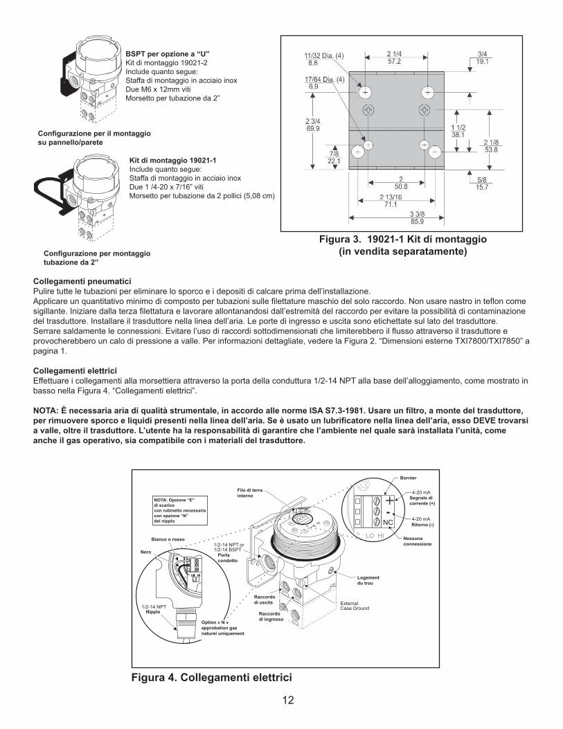
Collegamenti pneumaticiPulire tutte le tubazioni per eliminare lo sporco e i depositi di calcare prima dell’installazione.Applicare un quantitativo minimo di composto per tubazioni sulle filettature maschio del solo raccordo. Non usare nastro in teflon come sigillante. Iniziare dalla terza filettatura e lavorare allontanandosi dall’estremità del raccordo per evitare la possibilità di contaminazione del trasduttore. Installare il trasduttore nella linea dell’aria. Le porte di ingresso e uscita sono etichettate sul lato del trasduttore. Serrare saldamente le connessioni. Evitare l’uso di raccordi sottodimensionati che limiterebbero il flusso attraverso il trasduttore e provocherebbero un calo di pressione a valle. Per informazioni dettagliate, vedere la Figura 2. “Dimensioni esterne TXI7800/TXI7850” a pagina 1.
Collegamenti elettriciEffettuare i collegamenti alla morsettiera attraverso la porta della conduttura 1/2-14 NPT alla base dell’alloggiamento, come mostrato in basso nella Figura 4. “Collegamenti elettrici”.
NOTA: È necessaria aria di qualità strumentale, in accordo alle norme ISA S7.3-1981. Usare un filtro, a monte del trasduttore, per rimuovere sporco e liquidi presenti nella linea dell’aria. Se è usato un lubrificatore nella linea dell’aria, esso DEVE trovarsi a valle, oltre il trasduttore. L’utente ha la responsabilità di garantire che l’ambiente nel quale sarà installata l’unità, come anche il gas operativo, sia compatibile con i materiali del trasduttore.
Figura 4. Collegamenti elettrici
“N”OptionNaturalGasApprovalOnly
NOTE:TappedExhaustOption“E”RequiredwithNippleOption“N”
TerminalBlock(TB1)
Figura 3. 19021-1 Kit di montaggio(in vendita separatamente)
Configurazione per il montaggio su pannello/parete
BSPT per opzione a “U”Kit di montaggio 19021-2Include quanto segue:Staffa di montaggio in acciaio inoxDue M6 x 12mm vitiMorsetto per tubazione da 2”
Kit di montaggio 19021-1Include quanto segue:Staffa di montaggio in acciaio inoxDue 1 /4-20 x 7/16” vitiMorsetto per tubazione da 2 pollici (5,08 cm)
Configurazione per montaggio tubazione da 2”
NOTA: Opzione “E”di scaricocon rubinetto necessaria con opzione “N”del nipplo
Bianco o rosso
Nero
Nipplo
Option « N » approbation gaz naturel uniquement
Filo di terra interno
Portacondotto
Raccordo di uscita
Raccordodi ingresso
Bornier
Segnale di corrente (+)
Ritorno (-)
Nessunaconnessione
Logement du trou
13
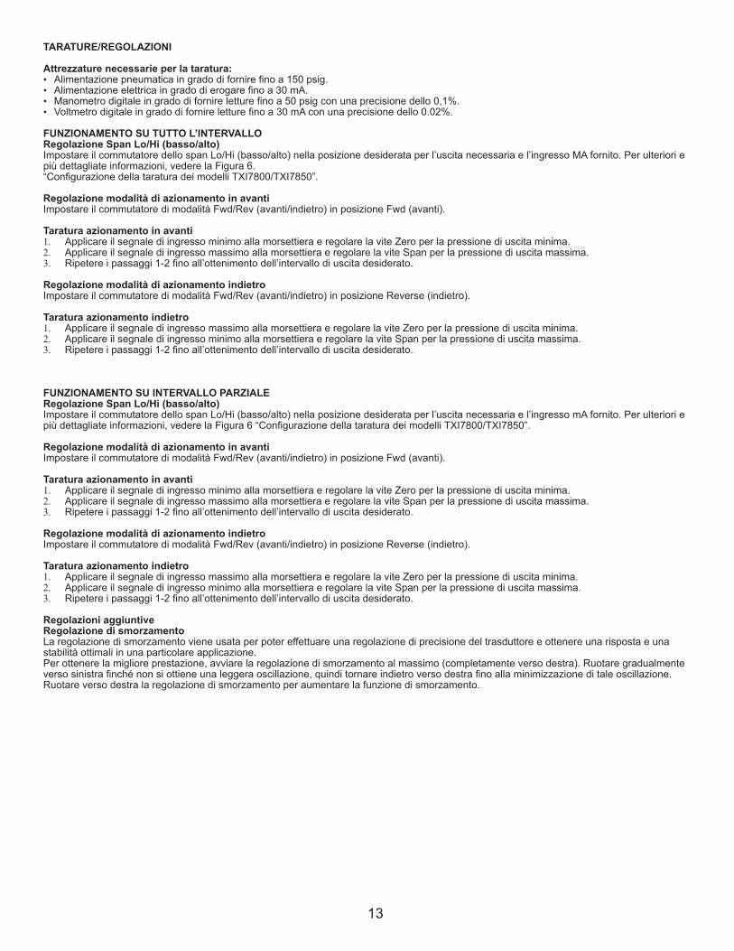
TARATURE/REGOLAZIONI
Attrezzature necessarie per la taratura:• Alimentazione pneumatica in grado di fornire fino a 150 psig.• Alimentazione elettrica in grado di erogare fino a 30 mA.• Manometro digitale in grado di fornire letture fino a 50 psig con una precisione dello 0,1%.• Voltmetro digitale in grado di fornire letture fino a 30 mA con una precisione dello 0.02%.
FUNZIONAMENTO SU TUTTO L’INTERVALLORegolazione Span Lo/Hi (basso/alto)Impostare il commutatore dello span Lo/Hi (basso/alto) nella posizione desiderata per l’uscita necessaria e l’ingresso MA fornito. Per ulteriori e più dettagliate informazioni, vedere la Figura 6.“Configurazione della taratura dei modelli TXI7800/TXI7850”.
Regolazione modalità di azionamento in avantiImpostare il commutatore di modalità Fwd/Rev (avanti/indietro) in posizione Fwd (avanti).
Taratura azionamento in avanti1. Applicare il segnale di ingresso minimo alla morsettiera e regolare la vite Zero per la pressione di uscita minima.2. Applicare il segnale di ingresso massimo alla morsettiera e regolare la vite Span per la pressione di uscita massima.3. Ripetere i passaggi 1-2 fino all’ottenimento dell’intervallo di uscita desiderato.
Regolazione modalità di azionamento indietroImpostare il commutatore di modalità Fwd/Rev (avanti/indietro) in posizione Reverse (indietro).
Taratura azionamento indietro1. Applicare il segnale di ingresso massimo alla morsettiera e regolare la vite Zero per la pressione di uscita minima.2. Applicare il segnale di ingresso minimo alla morsettiera e regolare la vite Span per la pressione di uscita massima.3. Ripetere i passaggi 1-2 fino all’ottenimento dell’intervallo di uscita desiderato.
FUNZIONAMENTO SU INTERVALLO PARZIALERegolazione Span Lo/Hi (basso/alto)Impostare il commutatore dello span Lo/Hi (basso/alto) nella posizione desiderata per l’uscita necessaria e l’ingresso mA fornito. Per ulteriori e più dettagliate informazioni, vedere la Figura 6 “Configurazione della taratura dei modelli TXI7800/TXI7850”.
Regolazione modalità di azionamento in avantiImpostare il commutatore di modalità Fwd/Rev (avanti/indietro) in posizione Fwd (avanti).
Taratura azionamento in avanti1. Applicare il segnale di ingresso minimo alla morsettiera e regolare la vite Zero per la pressione di uscita minima.2. Applicare il segnale di ingresso massimo alla morsettiera e regolare la vite Span per la pressione di uscita massima.3. Ripetere i passaggi 1-2 fino all’ottenimento dell’intervallo di uscita desiderato.
Regolazione modalità di azionamento indietroImpostare il commutatore di modalità Fwd/Rev (avanti/indietro) in posizione Reverse (indietro).
Taratura azionamento indietro1. Applicare il segnale di ingresso massimo alla morsettiera e regolare la vite Zero per la pressione di uscita minima. 2. Applicare il segnale di ingresso minimo alla morsettiera e regolare la vite Span per la pressione di uscita massima.3. Ripetere i passaggi 1-2 fino all’ottenimento dell’intervallo di uscita desiderato.
Regolazioni aggiuntiveRegolazione di smorzamentoLa regolazione di smorzamento viene usata per poter effettuare una regolazione di precisione del trasduttore e ottenere una risposta e una stabilità ottimali in una particolare applicazione.Per ottenere la migliore prestazione, avviare la regolazione di smorzamento al massimo (completamente verso destra). Ruotare gradualmente verso sinistra finché non si ottiene una leggera oscillazione, quindi tornare indietro verso destra fino alla minimizzazione di tale oscillazione. Ruotare verso destra la regolazione di smorzamento per aumentare la funzione di smorzamento.
14
LEGAL NOTICE:
The information set forth in the foregoing Installation, Operation and Maintenance Instructions shall not be modified or amend-
ed in any respect without prior written consent of Fairchild Industrial Products Company. In addition, the information set forth
herein shall be furnished with each product sold incorporating Fairchild's unit as a component thereof.
IS-500TXI78
REV 08/06
Litho in USA
HAZARDOUS AREA SPECIFICATIONS
ATEX Directive Nameplates
Table 1. Trouble-Shooting
Problem Solution (check)
No Output Supply Pressure
Clogged Orifice
Leakage Connections
Low or Improper Zero and Span Adjust
Span Adjust Supply Pressure Low
Output Leakage
Erratic Operation DC Signal
Loose Wires or Connections
Liquid in Air Supply
WARNING:
Failure of Transducer could result in output pressure increasing to supply
pressure possibly causing personal injury or damage to equipment.
Figure 6.
TXI7800/TXI7850 Calibration Configuration
0-30 0-2 0-200 HI
0-60 0-4 0-400 HI
0-120 0-8 0-800 HI
Input Output
psig BAR (kPa)
4-20 mA, 0-5, 1-5,0-10 & 1-9 VDC
SpanPosition
0-15 0-1 0-100 LO15-30 1-2 100-200 LO
0-30 0-2 0-200 LO30-60 2-4 200-400 LO
0-60 0-4 0-400 LO60-120 4-8 400-800 LO
Input Output
4-20 mA, 0-5, 1-5,0-10 & 1-9 VDC
Split Range Output.
psig BAR (kPa)
1
1 1 1
1
1 1
1 1
1
1 1 1
1
1 1
1 1
1
SpanPosition
Extended
Range
Units
Standard
Range
Unit
Standard Range Unit
Extended Range Unit
Service Kits for TXI7800/TXI7850
Series Ranges
TEXI/TAXI 3-15 psig, [0.2-1.0 Bar], (20-100 Kpa)
Kit part no. 19268-1 3-27 psig, [0.2-1.8 Bar], (20-180 Kpa)
6-30 psig, [0.4-2.0 Bar], (40-200 Kpa)
TCXI/TFX 3-15 psig, [0.2-1.0 Bar], (20-100 Kpa)
Kit part no. 19268-2 3-27 psig, [0.2-1.8 Bar], (20-180 Kpa)
6-30 psig, [0.4-2.0 Bar], (40-200 Kpa)
T*XI 0-30 psig, [0.0-2.0 Bar], (0-200 Kpa)
Kit part no. 19268-14
T*XI 0-60 psig, [0.0-4.0 Bar], (0-400 Kpa)
Kit part no. 19268-15
T*XI 0-120 psig, [0.0-8.0 Bar], (0-800 Kpa)
Kit part no. 19268-16
Figure 5.
Kit di riparazione per TXI7800/TXI7850Serie IntervalliTEXI/TAXINumero parte kit 19268-1
3-15 psig, [0.2-1.0 Bar], (20-100 Kpa)3-27 psig, [0.2-1.8 Bar], (20-180 Kpa)6-30 psig, [0.4-2.0 Bar], (40-200 Kpa)
TCXI/TFXNumero parte kit 19268-2
3-15 psig, [0.2-1.0 Bar], (20-100 Kpa)3-27 psig, [0.2-1.8 Bar], (20-180 Kpa)6-30 psig, [0.4-2.0 Bar], (40-200 Kpa)
T*XINumero parte kit 19268-14 0-30 psig, [0.0-2.0 Bar], (0-200 Kpa)
T*XINumero parte kit 19268-15 0-60 psig, [0.0-4.0 Bar], (0-400 Kpa)
T*XINumero parte kit 19268-16 0-120 psig, [0.0-8.0 Bar], (0-800 Kpa)
Figura 5. Figura 6.
Tabella 1. Risoluzione dei problemiProblema Soluzione (controllare)
Nessuna uscita Pressione di alimentazioneOrifizio intasato
Perdita Collegamenti
Bassa o impropriaRegolazione span
Regolazione zero e spanBassa pressione di alimentazionePerdita in uscita
Funzionamento irregolare Segnale DCConnessioni o fili lentiLiquidi nell’aria di alimentazione
AVVISO:Il guasto del trasduttore potrebbe provocare un aumento della pressione in uscita alla pressione di alimentazione e potrebbe provocare infortuni o danni alle attrezzature.
FUNZIONAMENTO SU TUTTO L’INTERVALLO
FUNZIONAMENTO SU INTERVALLO PARZIALE
Unidad de la gama estándar
Unità gamma standard
Unità gamma estesa
Unità gamma estesa
Configurazione della taratura
Ingresso
NOTA Le unità psig 3-27 e 6-30 non possono essere impostate per l’ingresso dell’intervallo parziale.
Morsettiera
Nipplo opzionale ½-14 NPT
Ingresso Produzione SpanPosizione
Sortie de la gamme fractionnée
Uscita intervallo parzialeIngresso intervallo parziale
Ingresso
Ingresso
Produzione
Produzione
Produzione
SpanPosizione
SpanPosizione
SpanPosizione

15
LEGAL NOTICE:
The information set forth in the foregoing Installation, Operation and Maintenance Instructions shall not be modified or amend-
ed in any respect without prior written consent of Fairchild Industrial Products Company. In addition, the information set forth
herein shall be furnished with each product sold incorporating Fairchild's unit as a component thereof.
IS-500TXI78
REV 08/06
Litho in USA
HAZARDOUS AREA SPECIFICATIONS
ATEX Directive Nameplates
Table 1. Trouble-Shooting
Problem Solution (check)
No Output Supply Pressure
Clogged Orifice
Leakage Connections
Low or Improper Zero and Span Adjust
Span Adjust Supply Pressure Low
Output Leakage
Erratic Operation DC Signal
Loose Wires or Connections
Liquid in Air Supply
WARNING:
Failure of Transducer could result in output pressure increasing to supply
pressure possibly causing personal injury or damage to equipment.
Figure 6.
TXI7800/TXI7850 Calibration Configuration
0-30 0-2 0-200 HI
0-60 0-4 0-400 HI
0-120 0-8 0-800 HI
Input Output
psig BAR (kPa)
4-20 mA, 0-5, 1-5,0-10 & 1-9 VDC
SpanPosition
0-15 0-1 0-100 LO15-30 1-2 100-200 LO
0-30 0-2 0-200 LO30-60 2-4 200-400 LO
0-60 0-4 0-400 LO60-120 4-8 400-800 LO
Input Output
4-20 mA, 0-5, 1-5,0-10 & 1-9 VDC
Split Range Output.
psig BAR (kPa)
1
1 1 1
1
1 1
1 1
1
1 1 1
1
1 1
1 1
1
SpanPosition
Extended
Range
Units
Standard
Range
Unit
Standard Range Unit
Extended Range Unit
Service Kits for TXI7800/TXI7850
Series Ranges
TEXI/TAXI 3-15 psig, [0.2-1.0 Bar], (20-100 Kpa)
Kit part no. 19268-1 3-27 psig, [0.2-1.8 Bar], (20-180 Kpa)
6-30 psig, [0.4-2.0 Bar], (40-200 Kpa)
TCXI/TFX 3-15 psig, [0.2-1.0 Bar], (20-100 Kpa)
Kit part no. 19268-2 3-27 psig, [0.2-1.8 Bar], (20-180 Kpa)
6-30 psig, [0.4-2.0 Bar], (40-200 Kpa)
T*XI 0-30 psig, [0.0-2.0 Bar], (0-200 Kpa)
Kit part no. 19268-14
T*XI 0-60 psig, [0.0-4.0 Bar], (0-400 Kpa)
Kit part no. 19268-15
T*XI 0-120 psig, [0.0-8.0 Bar], (0-800 Kpa)
Kit part no. 19268-16
Figure 5.
•Ex ia IIB T4 Ga Ex iaD 20 T90ºC Da SIRA 11ATEX2161X II 1 GD (Ta -40ºC to +80ºC) SYST DWG ED-18972 Ui=28V Ii=100mA Pi=0.7W Ci=0 Li=0
0518
CATALOG NO. TEXI78 -4 INPUT 4-20mAOUTPUTSUPPLY MAX.SUPPLY MIN. OVER MAX. OUTPUTMAXIMUM OPERATING VOLTAGE 30 VDC
Cablaggi in aree pericoloseI cablaggi nelle aree pericolose devono essere gestiti in conformità alle tabelle 2 e 3, e a tutti i codici locali applicabili.
Tabella 3 – Connessioni intrinsecamente sicureGruppo di sottoscrizione Numero disegno
FM (Factory Mutual) EC-18970
CSA (Canadian Standards Assoc.) EC-18971
ATEX EC-18972
Tabella 2 – Pratiche di cablaggio in luoghi pericolosiPaese Agenzia Codice
U.S. FM ANSI/ISA RP 12.6ANSI/NFPA70
Canada CSA CEC Part1
Europa ATEX EN 50 0392 EN 60079-14,IEC 60079-14
Globale IECEx IEC 60079-14
Tablella 4 - Consumo d’aria massimaConsumo d’aria Setpoint Unità
30 PSIG
[2.0] [BAR]
(200) (kPa)
SCFH/(m3/Hr) 13.5/(0.38)
SPECIFICHE AREA PERICOLOSATarghette direttiva ATEX
I termini specifici della agenzia di regolamentazione per l’uso e l’installazioneL’involucro è realizzato in lega di alluminio a base. In rari casi, le fonti di accensione a causa di scintille, possono verificarsi attrito o urto. Ciò deve essere tenuto in considerazione quando l’apparecchiatura è installata in aree che richiedono specificamente Equipment Group II, categoria 1G o Classe I, Divisione 1.
Strutture CSA per aree di Classe I, Divisione 1 Gruppo D con il gas come elementi principali della pressione di alimentazione devono essere installati con una opzione di scarico filettato, o il cliente deve fornire un adeguato spurgo della zona classificata, sulla base del velocità di spurgo e il numero di unità in funzione. La velocità di flusso di spurgo fornita nella tabella per le unità è impostazione massima di uscita 30 PSIG, indipendentemente dalla pressione di alimentazione ad un massimo di 125 PSIG.
Le informazioni contenute in queste istruzioni per l’installazione, il funzionamento e la manutenzione non deve in alcun caso essere modificato o modificato senza la previa autorizzazione scritta della società Fairchild Industrial Products. Inoltre, le informazioni contenute in questo documento dovrebbe essere fornita con ogni prodotto venduto che incorpora un’unità Fairchild.
INFORMATIVA LEGALE

16
FAIRCHILD TXI7800/TXI7850
EXPLOSION-PROOF I/P TRANSDUCERS
Installation,Operation and Maintenance Instructions
MAINTENANCE
To clean the Orifice, use the following procedure:
1. Shut off the valve that is supplying air to transducer. It is not necessary to remove the Transducer from the air line.
2. Remove the Orifice Assembly from the unit. For more detailed information see View A.
3. Clean with alcohol and dry with compressed air.
4. Lubricate O-Rings on Orifice Assembly (4) with silicone grease or equivalent lubricant before reassembling.
NOTES:
Parts must be completely dry before reassembling.If the standard maintenance procedure does not correct the trouble, a service
kit containing a replacement diaphragm and orifice assembly is available, see Figure 5.
The Model TXI7800/TXI7850 can be mounted directly onto a flat surface using the two tapped mounting holes in the mounting
face of the housing. For more information, see Figure 2.
TXI7800/TXI7850, Installation with the "N" Option.
NOTE: For Hazardous Location in Potentially Explosive Atmosphere Installations
1. Tapped exhaust required for installation in Class 1, Division 2/Zone 2 (European Union) classified locations with
group D/Group IIA (European Union) gases such as Natural Gas and Methane-Industrial as the pressure supply medium.
2. The explosion-proof pipe nipple seal (N option) supplied with this unit is an integral component of the design safety
of this version and must not be removed. Use caution to avoid marring the threads on the pipe nipple which voids the
explosion-proof integrity of the device.
3. Gases used as the pressure supply medium in hazardous location applications must be compatible with the elas-
tomer indicated in Materials of Construction.
A mounting Kit is available to mount the TXI7800/TXI7850 on a flat surface or on a 2" pipe. For more information, see Figure 3.
INSTALLATION
Figure 2. TXI7800/TXI7850 Outline Dimensions.
Materials of Construction
Body and Housing . Cromate Treated
Aluminum
Orifice . . . . . . . . . . Aluminum
and Sapphire
Trim . . . . . . . . . . . . Stainless Steel, Brass
and Zinc Plated Steel
Sintered Elements . Stainless Steel
Elastomers . . . . . . .Nitrile
Finish . . . . . . . . . . . Epoxy Powder Coating
NOTE: Unused IN and OUT Ports are plugged.
Standard Range Unit
Extended Range Unit
GENERAL INFORMATION
The Model TXI7800/TXI7850 Explosion-Proof I/P Transducer transmits a pneumatic signal which is linearly proportional to a DC
input signal from electronic control devices. The Transducer uses low powered microelectronics and pressure feedback control
to provide a stable, accurate pneumatic output for the operation of valve actuators.
Figure 2.
Figure 2.
TXI7800/TXI7850 FAIRCHILD TRANSMETTEURS I/P ANTIDÉFLAGRANTS
Instructions d’installation, de fonctionnement et de maintenance Dimensiones
Unité de la gamme standardTROUS DE MONTAGE ¼-20 UNC x 0.44 DE PROFONDEUR OU M6-1
VUE DE GAUCHE
RACCORD DE CONDUIT ½-14 NPTF OU ½-14 BSPT
VUE A
BORNE DE TERRE EXTÉRIEURE
ENTRÉE TARAUDÉE OPTIONNELLE 1/8-27 NPTF OU 1/8-28 BSPT
ORIFICES D’ENTRÉE ET DE SORTIE ¼-18 NPTF OU ¼-19 BSPT
VUE DE FACE
Raccord fileté ½-14 NPT
Évents (garder propre)
VUE A
Unité de la gamme étendueTROUS DE MONTAGE ¼-20 UNC x 0.44 DE PROFONDEUR OU M6-1
VUE DE GAUCHE
VUE A
VUE DE FACE
RACCORD DE CONDUIT ½-14 NPTF OU ½-14 BSPT
BORNE DE TERRE EXTÉRIEURE
ENTRÉE TARAUDÉE OPTIONNELLE (2 POSITIONS) 1/8-27 NPTF OU 1/8-28 BSPT
ORIFICES D’ENTRÉE ET DE SORTIE ¼-18 NPTF OU ¼-19 BSPT
Corps et Boîtier .................... Aluminium chroméOrifice ................................... Aluminium et saphirGarniture .............................. Acier inoxydable et acier zinguéÉléments frittés .................... Acier inoxydableElastomères ........................ NitrileFinition ................................. Revêtement en poudre époxy
Matériaux de construction
NOTE: Les orifices d’entrée et de sortie inutilisés sont bouchés.
INFORMATIONS GÉNÉRALESLe modèle de transmetteur I/P antidéflagrant TXI7800/TXI7850 transmet un signal pneumatique qui est linéairement proportionnel au signal d’entrée CC de dispositifs de contrôle électroniques. Le transmetteur est équipé d’une microélectronique de faible puissance et d’une commande rétroactive de la pression pour offrir une sortie pneumatique stable et précise pour le fonctionnement des motorisations de vannes.
INSTALLATIONLe modèle TXI7800/TXI7850 peut être monté directement sur une surface plane en utilisant les deux trous de montage taraudés situés sur la surface de montage du carter. Pour plus d’informations, voir la figure 2.
TXI7800/TXI7850, Installation avec l’option « N ».NOTE: Pour des installations en zones dangereuses dans des atmosphères potentiellement explosives1. Une entrée taraudée est requise pour une installation dans des lieux classés Classe 1, Division 2/Zone 2 (Union européenne) avec des gaz Groupe
D/Groupe IIA (Union européenne) tels que le gaz naturel et le méthane en tant qu’élément principal de la pression d’alimentation.2. Le joint antidéflagrant du raccord fileté du tuyau (option N) fourni avec cette unité fait partie intégrante de la sécurité de conception de cette version
et ne doit pas être retiré. Veillez à ne pas abîmer les filets du raccord fileté du tuyau, ce qui annulerait l’intégrité antidéflagrante du dispositif. 3. Les gaz utilisés comme éléments principaux de la pression d’alimentation pour les applications en zones dangereuses doivent être compatibles
avec l’élastomère indiqué dans les matériaux de construction.
Un kit de montage est disponible pour monter le TXI7800/TXI7850 sur une surface plane ou sur un tuyau 2”. Pour plus d’informations, voir la figure 3.
MAINTENANCE Pour nettoyer l’orifice, utilisez la procédure suivante : 1. Fermez la vanne qui alimente le transmetteur en air. Il n’est pas nécessaire de retirer le transmetteur du conduit d’air.2. Retirez l’assemblage de l’orifice de l’unité. Pour plus de détails, voir la vue A.3. Nettoyez avec de l’alcool et séchez à l’air comprimé. 4. Avant le réassemblage, lubrifiez les joints toriques sur l’assemblage de l’orifice (4) avec de la graisse de silicone ou un lubrifiant équivalent.NOTES: Les pièces doivent être complètement sèches avant le réassemblage. Si la procédure de maintenance standard ne règle pas le problème, un kit de maintenance comprenant un diaphragme de remplacement et un assemblage d’orifice est disponible. Voir figure 5.
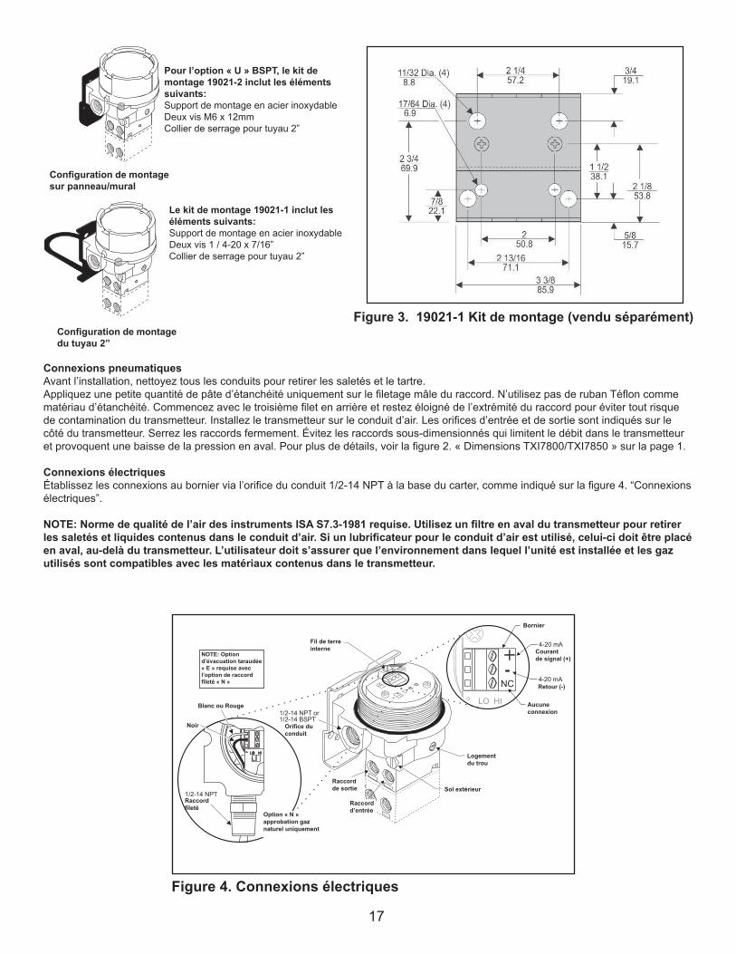
172
For "U" option BSPT
Mounting Kit 19021-2
Includes the following:
Stainless Steel Mounting Bracket
Two M6 X 12mm Screws
2" Pipe Clamp
Mounting Kit 19021-1
Includes the following:
Stainless Steel Mounting Bracket
Two 1/4-20 x 7/16" Screws
2" Pipe Clamp
Figure 3. Mounting Kit 19021-1. (Sold Separately)
Panel / Wall
Mounting
Configuration
2" Pipe Mounting
Configuration
Pneumatic Connections
Clean all pipelines to remove dirt and scale before installation.
Apply a minimum amount of pipe compound to the male threads of the fitting only. Do not use teflon tape as a sealant. Start with the third
thread back and work away from the end of the fitting to avoid the possibility of contaminating the transducer. Install the transducer in the air
line. The inlet and outlet ports are labeled on the side of the transducer. Tighten connections securely. Avoid undersized fittings that will limit
the flow through the transducer and cause a pressure drop downstream. For detailed information, see Figure 2. “TXI7800/TXI7850 Outline
Dimensions” on page 1.
Electric Connections
Make connections to the Terminal Block through the 1/2-14 NPT Conduit Port in the base of the housing as shown below in Figure 4.
“Electrical Connections”.
Wiring in Hazardous Areas
Wiring in hazardous areas should be performed in
accordance with T_ _able 1. and any local codes
that apply.
NOTE: Instrument quality air, per ISA Standards S7.3-1981, is required. Use a filter, ahead of the transducer, to remove dirt and
liquid in the air line. If an air line lubricator is used, it MUST be located downstream, beyond the transducer.
The user is responsible for insuring that the environment in which the unit will be installed, and the operating gas, is compati-
ble with the materials in the transducer.
Figure 4. Electrical Connections.
“N”Option
NaturalGas
ApprovalOnly
NOTE:
TappedExhaust
Option“E”
Requiredwith
NippleOption“N”
Terminal
Block(TB1)
Table1. Hazardous Location Wiring Practices
Country Agency Code
U.S. FM ANSI/ISA RP 12.6
ANSI/NFPA70
Canada CSA CEC Part1
Europe ATEX EN 50 039, EN 60079-
14, IEC 60079-14
Australia SAA AS/NZS 3000, AS2381.1
Table 2. Intrinsically Safe Connections
Underwriting Group Drawing Number
FM (Factory Mutual) EC- 18970
CSA (Canadian Standards Assoc.) EC- 18971
ATEX EC- 18972
SAA (Standard Australia Assoc.) EC- 19271
Intrinsically Safe Connections
Refer to the latest revision of the indicated drawing.
Connexions pneumatiquesAvant l’installation, nettoyez tous les conduits pour retirer les saletés et le tartre.Appliquez une petite quantité de pâte d’étanchéité uniquement sur le filetage mâle du raccord. N’utilisez pas de ruban Téflon comme matériau d’étanchéité. Commencez avec le troisième filet en arrière et restez éloigné de l’extrémité du raccord pour éviter tout risque de contamination du transmetteur. Installez le transmetteur sur le conduit d’air. Les orifices d’entrée et de sortie sont indiqués sur le côté du transmetteur. Serrez les raccords fermement. Évitez les raccords sous-dimensionnés qui limitent le débit dans le transmetteur et provoquent une baisse de la pression en aval. Pour plus de détails, voir la figure 2. « Dimensions TXI7800/TXI7850 » sur la page 1.
Connexions électriquesÉtablissez les connexions au bornier via l’orifice du conduit 1/2-14 NPT à la base du carter, comme indiqué sur la figure 4. “Connexions électriques”.
NOTE: Norme de qualité de l’air des instruments ISA S7.3-1981 requise. Utilisez un filtre en aval du transmetteur pour retirer les saletés et liquides contenus dans le conduit d’air. Si un lubrificateur pour le conduit d’air est utilisé, celui-ci doit être placé en aval, au-delà du transmetteur. L’utilisateur doit s’assurer que l’environnement dans lequel l’unité est installée et les gaz utilisés sont compatibles avec les matériaux contenus dans le transmetteur.
Figure 4. Connexions électriques
“N”OptionNaturalGasApprovalOnly
NOTE:TappedExhaustOption“E”RequiredwithNippleOption“N”
TerminalBlock(TB1)
Figure 3. 19021-1 Kit de montage (vendu séparément)
Configuration de montage sur panneau/mural
Pour l’option « U » BSPT, le kit de montage 19021-2 inclut les éléments suivants:Support de montage en acier inoxydableDeux vis M6 x 12mmCollier de serrage pour tuyau 2”
Le kit de montage 19021-1 inclut les éléments suivants:Support de montage en acier inoxydableDeux vis 1 / 4-20 x 7/16”Collier de serrage pour tuyau 2”
Configuration de montage du tuyau 2”
NOTE: Option d’évacuation taraudée « E » requise avec l’option de raccord fileté « N »
Blanc ou Rouge
Noir
Raccord fileté
Option « N » approbation gaz naturel uniquement
Fil de terre interne
Orifice du conduit
Raccord de sortie
Raccord d’entrée
Bornier
Courantde signal (+)
Retour (-)
Aucuneconnexion
Logement du trou
Sol extérieur
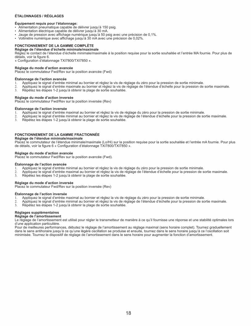
18
ÉTALONNAGES / RÉGLAGES
Équipement requis pour l’étalonnage:• Alimentation pneumatique capable de délivrer jusqu’à 150 psig.• Alimentation électrique capable de délivrer jusqu’à 30 mA.• Jauge de pression avec affichage numérique jusqu’à 50 psig avec une précision de 0,1%.• Voltmètre numérique avec affichage jusqu’à 30 mA avec une précision de 0,02%.
FONCTIONNEMENT DE LA GAMME COMPLÈTERéglage de l’étendue d’échelle minimale/maximaleRéglez le contact de l’étendue d’échelle minimale/maximale à la position requise pour la sortie souhaitée et l’entrée MA fournie. Pour plus de détails, voir la figure 6.« Configuration d’étalonnage TXI7800/TXI7850 ».
Réglage du mode d’action avancéePlacez le commutateur Fwd/Rev sur la position avancée (Fwd)
Étalonnage de l’action avancée1. Appliquez le signal d’entrée minimal au bornier et réglez la vis de réglage du zéro pour la pression de sortie minimale.2. Appliquez le signal d’entrée maximale au bornier et réglez la vis de réglage de l’étendue d’échelle pour la pression de sortie maximale.3. Répétez les étapes 1-2 jusqu’à obtenir la plage de sortie souhaitée.
Réglage du mode d’action inverséePlacez le commutateur Fwd/Rev sur la position inversée (Rev)
Étalonnage de l’action inversée1. Appliquez le signal d’entrée maximal au bornier et réglez la vis de réglage du zéro pour la pression de sortie minimale.2. Appliquez le signal d’entrée minimal au bornier et réglez la vis de réglage de l’étendue d’échelle pour la pression de sortie maximale.3. Répétez les étapes 1-2 jusqu’à obtenir la plage de sortie souhaitée.
FONCTIONNEMENT DE LA GAMME FRACTIONNÉERéglage de l’étendue minimale/maximalePlacez le commutateur de l’étendue minimale/maximale (Lo/Hi) sur la position requise pour la sortie souhaitée et l’entrée mA fournie. Pour plus de détails, voir la figure 6 « Configuration d’étalonnage TXI7800/TXI7850 ».
Réglage du mode d’action avancéePlacez le commutateur Fwd/Rev sur la position avancée (Fwd).
Étalonnage de l’action avancée1. Appliquez le signal d’entrée minimal au bornier et réglez la vis de réglage du zéro pour la pression de sortie minimale.2. Appliquez le signal d’entrée maximal au bornier et réglez la vis de réglage de l’étendue d’échelle pour la pression de sortie maximale.3. Répétez les étapes 1-2 jusqu’à obtenir la plage de sortie souhaitée.
Réglage du mode d’action inverséePlacez le commutateur Fwd/Rev sur la position inversée (Rev)
Étalonnage de l’action inversée1. Appliquez le signal d’entrée maximal au bornier et réglez la vis de réglage du zéro pour la pression de sortie minimale. 2. Appliquez le signal d’entrée minimal au bornier et réglez la vis de réglage de l’étendue d’échelle pour la pression de sortie maximale.3. Répétez les étapes 1-2 jusqu’à obtenir la plage de sortie souhaitée.
Réglages supplémentairesRéglage de l’amortissementLe réglage de l’amortissement est utilisé pour régler le transmetteur de manière à ce qu’il fournisse une réponse et une stabilité optimales lors d’une application particulière.Pour de meilleures performances, débutez le réglage de l’amortissement au réglage maximal (sens horaire complet). Tournez graduellement dans le sens antihoraire jusqu’à ce qu’une légère oscillation se produise et ensuite, tournez dans le sens horaire jusqu’à ce l’oscillation soit minimisée. Tournez le dispositif de réglage de l’amortissement dans le sens horaire pour augmenter la fonction d’amortissement.
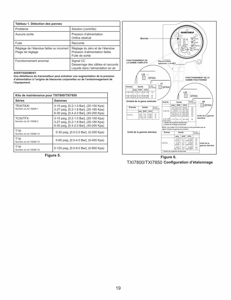
19
LEGAL NOTICE:
The information set forth in the foregoing Installation, Operation and Maintenance Instructions shall not be modified or amend-
ed in any respect without prior written consent of Fairchild Industrial Products Company. In addition, the information set forth
herein shall be furnished with each product sold incorporating Fairchild's unit as a component thereof.
IS-500TXI78
REV 08/06
Litho in USA
HAZARDOUS AREA SPECIFICATIONS
ATEX Directive Nameplates
Table 1. Trouble-Shooting
Problem Solution (check)
No Output Supply Pressure
Clogged Orifice
Leakage Connections
Low or Improper Zero and Span Adjust
Span Adjust Supply Pressure Low
Output Leakage
Erratic Operation DC Signal
Loose Wires or Connections
Liquid in Air Supply
WARNING:
Failure of Transducer could result in output pressure increasing to supply
pressure possibly causing personal injury or damage to equipment.
Figure 6.
TXI7800/TXI7850 Calibration Configuration
0-30 0-2 0-200 HI
0-60 0-4 0-400 HI
0-120 0-8 0-800 HI
Input Output
psig BAR (kPa)
4-20 mA, 0-5, 1-5,0-10 & 1-9 VDC
SpanPosition
0-15 0-1 0-100 LO15-30 1-2 100-200 LO
0-30 0-2 0-200 LO30-60 2-4 200-400 LO
0-60 0-4 0-400 LO60-120 4-8 400-800 LO
Input Output
4-20 mA, 0-5, 1-5,0-10 & 1-9 VDC
Split Range Output.
psig BAR (kPa)
1
1 1 1
1
1 1
1 1
1
1 1 1
1
1 1
1 1
1
SpanPosition
Extended
Range
Units
Standard
Range
Unit
Standard Range Unit
Extended Range Unit
Service Kits for TXI7800/TXI7850
Series Ranges
TEXI/TAXI 3-15 psig, [0.2-1.0 Bar], (20-100 Kpa)
Kit part no. 19268-1 3-27 psig, [0.2-1.8 Bar], (20-180 Kpa)
6-30 psig, [0.4-2.0 Bar], (40-200 Kpa)
TCXI/TFX 3-15 psig, [0.2-1.0 Bar], (20-100 Kpa)
Kit part no. 19268-2 3-27 psig, [0.2-1.8 Bar], (20-180 Kpa)
6-30 psig, [0.4-2.0 Bar], (40-200 Kpa)
T*XI 0-30 psig, [0.0-2.0 Bar], (0-200 Kpa)
Kit part no. 19268-14
T*XI 0-60 psig, [0.0-4.0 Bar], (0-400 Kpa)
Kit part no. 19268-15
T*XI 0-120 psig, [0.0-8.0 Bar], (0-800 Kpa)
Kit part no. 19268-16
Figure 5.
Kits de maintenance pour TXI7800/TXI7850Séries GammesTEXI/TAXINuméro du kit 19268-1
3-15 psig, [0.2-1.0 Bar], (20-100 Kpa)3-27 psig, [0.2-1.8 Bar], (20-180 Kpa)6-30 psig, [0.4-2.0 Bar], (40-200 Kpa)
TCXI/TFXNuméro du kit 19268-2
3-15 psig, [0.2-1.0 Bar], (20-100 Kpa)3-27 psig, [0.2-1.8 Bar], (20-180 Kpa)6-30 psig, [0.4-2.0 Bar], (40-200 Kpa)
T*XINuméro du kit 19268-14 0-30 psig, [0.0-2.0 Bar], (0-200 Kpa)
T*XINuméro du kit 19268-15 0-60 psig, [0.0-4.0 Bar], (0-400 Kpa)
T*XINuméro du kit 19268-16 0-120 psig, [0.0-8.0 Bar], (0-800 Kpa)
Figure 5. Figure 6.
Tableau 1. Détection des pannesProblème Solution (contrôle)
Aucune sortie Pression d’alimentationOrifice obstrué
Fuite Raccords
Réglage de l’étendue faible ou incorrectPlage de réglage
Réglage du zéro et de l’étenduePression d’alimentation faibleFuite de sortie
Fonctionnement anormal Signal CCDesserrage des câbles et raccordsLiquide dans l’alimentation en air
AVERTISSEMENT:Une défaillance du transmetteur peut entraîner une augmentation de la pression d’alimentation à l’origine de blessures corporelles ou de l’endommagement de l’équipement.
FONCTIONNEMENT DE LA GAMME COMPLÈTE
FONCTIONNEMENT DE LA GAMME FRACTIONNÉE
Unidad de la gama estándar
Unité de la gamme standard
Unité de la gamme étendue
Unité de la gamme étendue
Configuration d’étalonnage
Entrada Salida
SortieEntrée
Entrée Sortie
NOTE: Les unités 3-27 et 6-30 psig ne vous permettra pas de régler l’entrée de gamme de scission.
Bornier
Raccord fileté optionnel ½-14 NPT
Entrée Sortie Positionde l’étendue
Positionde l’étendue
Positionde l’étendue
Sortie de la gamme fractionnée
Sortie de la gamme fractionnéeEntrée de la plage fractionnée
Positionde l’étendue
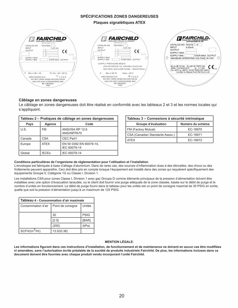
20
LEGAL NOTICE:
The information set forth in the foregoing Installation, Operation and Maintenance Instructions shall not be modified or amend-
ed in any respect without prior written consent of Fairchild Industrial Products Company. In addition, the information set forth
herein shall be furnished with each product sold incorporating Fairchild's unit as a component thereof.
IS-500TXI78
REV 08/06
Litho in USA
HAZARDOUS AREA SPECIFICATIONS
ATEX Directive Nameplates
Table 1. Trouble-Shooting
Problem Solution (check)
No Output Supply Pressure
Clogged Orifice
Leakage Connections
Low or Improper Zero and Span Adjust
Span Adjust Supply Pressure Low
Output Leakage
Erratic Operation DC Signal
Loose Wires or Connections
Liquid in Air Supply
WARNING:
Failure of Transducer could result in output pressure increasing to supply
pressure possibly causing personal injury or damage to equipment.
Figure 6.
TXI7800/TXI7850 Calibration Configuration
0-30 0-2 0-200 HI
0-60 0-4 0-400 HI
0-120 0-8 0-800 HI
Input Output
psig BAR (kPa)
4-20 mA, 0-5, 1-5,0-10 & 1-9 VDC
SpanPosition
0-15 0-1 0-100 LO15-30 1-2 100-200 LO
0-30 0-2 0-200 LO30-60 2-4 200-400 LO
0-60 0-4 0-400 LO60-120 4-8 400-800 LO
Input Output
4-20 mA, 0-5, 1-5,0-10 & 1-9 VDC
Split Range Output.
psig BAR (kPa)
1
1 1 1
1
1 1
1 1
1
1 1 1
1
1 1
1 1
1
SpanPosition
Extended
Range
Units
Standard
Range
Unit
Standard Range Unit
Extended Range Unit
Service Kits for TXI7800/TXI7850
Series Ranges
TEXI/TAXI 3-15 psig, [0.2-1.0 Bar], (20-100 Kpa)
Kit part no. 19268-1 3-27 psig, [0.2-1.8 Bar], (20-180 Kpa)
6-30 psig, [0.4-2.0 Bar], (40-200 Kpa)
TCXI/TFX 3-15 psig, [0.2-1.0 Bar], (20-100 Kpa)
Kit part no. 19268-2 3-27 psig, [0.2-1.8 Bar], (20-180 Kpa)
6-30 psig, [0.4-2.0 Bar], (40-200 Kpa)
T*XI 0-30 psig, [0.0-2.0 Bar], (0-200 Kpa)
Kit part no. 19268-14
T*XI 0-60 psig, [0.0-4.0 Bar], (0-400 Kpa)
Kit part no. 19268-15
T*XI 0-120 psig, [0.0-8.0 Bar], (0-800 Kpa)
Kit part no. 19268-16
Figure 5.
•Ex ia IIB T4 Ga Ex iaD 20 T90ºC Da SIRA 11ATEX2161X II 1 GD (Ta -40ºC to +80ºC) SYST DWG ED-18972 Ui=28V Ii=100mA Pi=0.7W Ci=0 Li=0
0518
CATALOG NO. TEXI78 -4 INPUT 4-20mAOUTPUTSUPPLY MAX.SUPPLY MIN. OVER MAX. OUTPUTMAXIMUM OPERATING VOLTAGE 30 VDC
Câblage en zones dangereusesLe câblage en zones dangereuses doit être réalisé en conformité avec les tableaux 2 et 3 et les normes locales qui s’appliquent.
Tableau 3 – Connexions à sécurité intrinsèqueGroupe d’évaluation Numéro du schéma
FM (Factory Mutual) EC-18970
CSA (Canadian Standards Assoc.) EC-18971
ATEX EC-18972
Tableau 2 – Pratiques de câblage en zones dangereusesPays Agence Code
U.S. FM ANSI/ISA RP 12.6ANSI/NFPA70
Canada CSA CEC Part1
Europe ATEX EN 50 0392 EN 60079-14,IEC 60079-14
Global IECEx IEC 60079-14
Tableau 4 - Consommation d’air maximaleConsommation d’air Point de consigne Unités
30 PSIG
[2.0] [BAR]
(200) (kPa)
SCFH/(m3/Hr) 13.5/(0.38)
SPÉCIFICATIONS ZONES DANGEREUSESPlaques signalétiques ATEX
Conditions particulières de l’organisme de réglementation pour l’utilisation et l’installationL’enveloppe est fabriquée à base d’alliage d’aluminium. Dans de rares cas, des sources d’inflammation dues à des étincelles, des chocs ou des frottements peuvent apparaître. Ceci doit être pris en compte lorsque l’équipement est installé dans des zones qui requièrent spécifiquement des équipements Groupe II, Catégorie 1G ou Classe I, Division 1.
Les installations CSA pour zones Classe I, Division 1 avec gaz Groupe D comme éléments principaux de la pression d’alimentation doivent être installées avec une option d’évacuation taraudée, ou le client doit fournir une purge adéquate de la zone classée, basée sur le débit de purge et le nombre d’unités en fonctionnement. Le débit de purge fourni dans le tableau pour les unités est un point de consigne maximal de 30 PSIG en sortie, quelle que soit la pression d’alimentation jusqu’à un maximum de 125 PSIG.
Les informations figurant dans ces instructions d’installation, de fonctionnement et de maintenance ne doivent en aucun cas être modifiées ni amendées, sans l’autorisation écrite préalable de la société de produits industriels Fairchild. De plus, les informations incluses dans ce document doivent être fournies avec chaque produit vendu incorporant l’unité Fairchild.
MENTION LÉGALE:
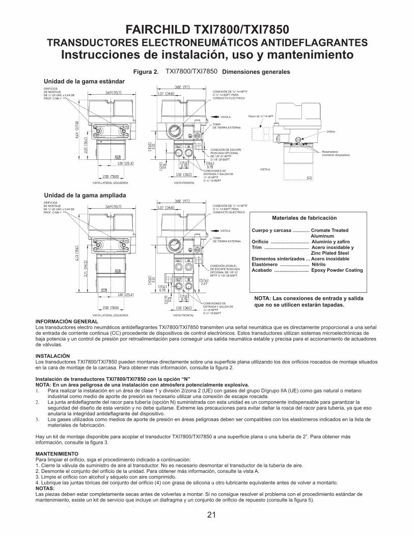
21
FAIRCHILD TXI7800/TXI7850
EXPLOSION-PROOF I/P TRANSDUCERS
Installation,Operation and Maintenance Instructions
MAINTENANCE
To clean the Orifice, use the following procedure:
1. Shut off the valve that is supplying air to transducer. It is not necessary to remove the Transducer from the air line.
2. Remove the Orifice Assembly from the unit. For more detailed information see View A.
3. Clean with alcohol and dry with compressed air.
4. Lubricate O-Rings on Orifice Assembly (4) with silicone grease or equivalent lubricant before reassembling.
NOTES:
Parts must be completely dry before reassembling.If the standard maintenance procedure does not correct the trouble, a service
kit containing a replacement diaphragm and orifice assembly is available, see Figure 5.
The Model TXI7800/TXI7850 can be mounted directly onto a flat surface using the two tapped mounting holes in the mounting
face of the housing. For more information, see Figure 2.
TXI7800/TXI7850, Installation with the "N" Option.
NOTE: For Hazardous Location in Potentially Explosive Atmosphere Installations
1. Tapped exhaust required for installation in Class 1, Division 2/Zone 2 (European Union) classified locations with
group D/Group IIA (European Union) gases such as Natural Gas and Methane-Industrial as the pressure supply medium.
2. The explosion-proof pipe nipple seal (N option) supplied with this unit is an integral component of the design safety
of this version and must not be removed. Use caution to avoid marring the threads on the pipe nipple which voids the
explosion-proof integrity of the device.
3. Gases used as the pressure supply medium in hazardous location applications must be compatible with the elas-
tomer indicated in Materials of Construction.
A mounting Kit is available to mount the TXI7800/TXI7850 on a flat surface or on a 2" pipe. For more information, see Figure 3.
INSTALLATION
Figure 2. TXI7800/TXI7850 Outline Dimensions.
Materials of Construction
Body and Housing . Cromate Treated
Aluminum
Orifice . . . . . . . . . . Aluminum
and Sapphire
Trim . . . . . . . . . . . . Stainless Steel, Brass
and Zinc Plated Steel
Sintered Elements . Stainless Steel
Elastomers . . . . . . .Nitrile
Finish . . . . . . . . . . . Epoxy Powder Coating
NOTE: Unused IN and OUT Ports are plugged.
Standard Range Unit
Extended Range Unit
GENERAL INFORMATION
The Model TXI7800/TXI7850 Explosion-Proof I/P Transducer transmits a pneumatic signal which is linearly proportional to a DC
input signal from electronic control devices. The Transducer uses low powered microelectronics and pressure feedback control
to provide a stable, accurate pneumatic output for the operation of valve actuators.
Figura 2.
Figure 2.
FAIRCHILD TXI7800/TXI7850 TRANSDUCTORES ELECTRONEUMÁTICOS ANTIDEFLAGRANTES
Instrucciones de instalación, uso y mantenimiento Dimensiones generales
Unidad de la gama estándar ORIFICIOSDE MONTAJEDE ¼”-20 UNC x 0,44 DE PROF. O M6-1
VISTA LATERAL IZQUIERDA
CONEXIÓN DE ½”-14 NPTFO ½”-14 BSPT PARA CONDUCTO ELÉCTRICO
VISTA A
TOMADE TIERRA EXTERNA
CONEXIÓN DE ESCAPE ROSCADA OPCIONAL DE 1/8”-27 NPTFO 1/8”-28 BSPT
CONEXIONES DE ENTRADA Y SALIDA DE ¼”-18 NPTFO ¼”-19 BSPT
VISTA FRONTAL
Racor de ½”-14 NPT
Orificio
Respiraderos(mantener despejados)
VISTA A
Unidad de la gama ampliada ORIFICIOSDE MONTAJEDE ¼”-20 UNC x 0,44 DE PROF. O M6-1
VISTA LATERAL IZQUIERDA
VISTA A
VISTA FRONTAL
CONEXIÓN DE ½”-14 NPTFO ½”-14 BSPT PARA CONDUCTO ELÉCTRICO
TOMADE TIERRA EXTERNA
CONEXIÓN (DOBLE) DE ESCAPE ROSCADA OPCIONAL DE 1/8”-27 NPTF O 1/8”-28 BSPT
CONEXIONES DE ENTRADA Y SALIDA DE ¼”-18 NPTFO ¼”-19 BSPT
Cuerpo y carcasa ............. Cromate Treated AluminumOrificio ............................. Aluminio y zafiroTrim .................................. Acero inoxidable y Zinc Plated SteelElementos sinterizados ... Acero inoxidableElastómero ...................... NitriloAcabado .......................... Epoxy Powder Coating
Materiales de fabricación
NOTA: Las conexiones de entrada y salida que no se utilicen estarán tapadas.
INFORMACIÓN GENERALLos transductores electro neumáticos antideflagrantes TXI7800/TXI7850 transmiten una señal neumática que es directamente proporcional a una señal de entrada de corriente continua (CC) procedente de dispositivos de control electrónicos. Estos transductores utilizan sistemas microelectrónicas de baja potencia y un control de presión por retroalimentación para conseguir una salida neumática estable y precisa para el accionamiento de actuadores de válvulas.
INSTALACIÓNLos transductores TXI7800/TXI7850 pueden montarse directamente sobre una superficie plana utilizando los dos orificios roscados de montaje situados en la cara de montaje de la carcasa. Para obtener más información, consulte la figura 2.
Instalación de transductores TXI7800/TXI7850 con la opción “N”NOTA: En un área peligrosa de una instalación con atmósfera potencialmente explosiva.1. Para realizar la instalación en un área de clase 1 y división 2/zona 2 (UE) con gases del grupo D/grupo IIA (UE) como gas natural o metano
industrial como medio de aporte de presión es necesario utilizar una conexión de escape roscada.2. La junta antideflagrante del racor para tubería (opción N) suministrada con esta unidad es un componente indispensable para garantizar la
seguridad del diseño de esta versión y no debe quitarse. Extreme las precauciones para evitar dañar la rosca del racor para tubería, ya que eso anularía la integridad antideflagrante del dispositivo.
3. Los gases utilizados como medios de aporte de presión en áreas peligrosas deben ser compatibles con los elastómeros indicados en la lista de materiales de fabricación.
Hay un kit de montaje disponible para acoplar el transductor TXI7800/TXI7850 a una superficie plana o una tubería de 2”. Para obtener más información, consulte la figura 3.
MANTENIMIENTO Para limpiar el orificio, siga el procedimiento indicado a continuación: 1. Cierre la válvula de suministro de aire al transductor. No es necesario desmontar el transductor de la tubería de aire. 2. Desmonte el conjunto del orificio de la unidad. Para obtener más información, consulte la vista A. 3. Limpie el orificio con alcohol y séquelo con aire comprimido. 4. Lubrique las juntas tóricas del conjunto del orificio (4) con grasa de silicona u otro lubricante equivalente antes de volver a montarlo. NOTAS: Las piezas deben estar completamente secas antes de volverlas a montar. Si no consigue resolver el problema con el procedimiento estándar de mantenimiento, existe un kit de servicio que incluye un diafragma y un conjunto de orificio de repuesto (consulte la figura 5).

222
For "U" option BSPT
Mounting Kit 19021-2
Includes the following:
Stainless Steel Mounting Bracket
Two M6 X 12mm Screws
2" Pipe Clamp
Mounting Kit 19021-1
Includes the following:
Stainless Steel Mounting Bracket
Two 1/4-20 x 7/16" Screws
2" Pipe Clamp
Figure 3. Mounting Kit 19021-1. (Sold Separately)
Panel / Wall
Mounting
Configuration
2" Pipe Mounting
Configuration
Pneumatic Connections
Clean all pipelines to remove dirt and scale before installation.
Apply a minimum amount of pipe compound to the male threads of the fitting only. Do not use teflon tape as a sealant. Start with the third
thread back and work away from the end of the fitting to avoid the possibility of contaminating the transducer. Install the transducer in the air
line. The inlet and outlet ports are labeled on the side of the transducer. Tighten connections securely. Avoid undersized fittings that will limit
the flow through the transducer and cause a pressure drop downstream. For detailed information, see Figure 2. “TXI7800/TXI7850 Outline
Dimensions” on page 1.
Electric Connections
Make connections to the Terminal Block through the 1/2-14 NPT Conduit Port in the base of the housing as shown below in Figure 4.
“Electrical Connections”.
Wiring in Hazardous Areas
Wiring in hazardous areas should be performed in
accordance with T_ _able 1. and any local codes
that apply.
NOTE: Instrument quality air, per ISA Standards S7.3-1981, is required. Use a filter, ahead of the transducer, to remove dirt and
liquid in the air line. If an air line lubricator is used, it MUST be located downstream, beyond the transducer.
The user is responsible for insuring that the environment in which the unit will be installed, and the operating gas, is compati-
ble with the materials in the transducer.
Figure 4. Electrical Connections.
“N”Option
NaturalGas
ApprovalOnly
NOTE:
TappedExhaust
Option“E”
Requiredwith
NippleOption“N”
Terminal
Block(TB1)
Table1. Hazardous Location Wiring Practices
Country Agency Code
U.S. FM ANSI/ISA RP 12.6
ANSI/NFPA70
Canada CSA CEC Part1
Europe ATEX EN 50 039, EN 60079-
14, IEC 60079-14
Australia SAA AS/NZS 3000, AS2381.1
Table 2. Intrinsically Safe Connections
Underwriting Group Drawing Number
FM (Factory Mutual) EC- 18970
CSA (Canadian Standards Assoc.) EC- 18971
ATEX EC- 18972
SAA (Standard Australia Assoc.) EC- 19271
Intrinsically Safe Connections
Refer to the latest revision of the indicated drawing.
Conexiones neumáticasAntes de realizar la instalación, limpie todas las tuberías para eliminar la suciedad y las incrustaciones.Aplique una pequeña cantidad de producto de unión de tuberías solo en la rosca macho del racor. No utilice cinta de teflón como material de sellado. Comience a aplicar el producto desde la tercera vuelta de la rosca y en sentido opuesto al extremo del racor, para evitar una posible contaminación del transductor. Monte el transductor en la tubería de aire. Las conexiones de entrada y de salida están marcadas en la parte lateral del transductor. Apriete las conexiones firmemente. No utilice racores de un tamaño inferior al necesario, ya que limitarían el caudal que atraviesa el transductor y provocarían una caída de presión aguas abajo. Para obtener más información, consulte la figura 2, “Dimensiones generales de los transductores TXI7800/TXI7850”, en la página 1.
Conexiones eléctricasRealice las conexiones al bloque de terminales a través de la conexión para conducto eléctrico de 1/2”-14 NPT situada en la base de la carcasa, tal como se muestra en la figura 4, “Conexiones eléctricas”.
NOTA: Debe utilizar aire para instrumentación que cumpla los requisitos de la norma ISA S7.3-1981. Coloque un filtro antes del transductor para eliminar la suciedad y el líquido que puedan existir en la tubería de aire. Si utiliza un sistema de lubricación para la tubería de aire DEBE situarlo aguas abajo, después del transductor. El usuario es el responsable de garantizar que el entorno en el que se instale la unidad y el gas de trabajo sean compatibles con los materiales del transductor.
Figura 4. Conexiones eléctricas
“N”OptionNaturalGasApprovalOnly
NOTE:TappedExhaustOption“E”RequiredwithNippleOption“N”
TerminalBlock(TB1)
Figure 3. 19021-1Kit de montaje (comercializado por separado).
Configuración de montaje en panel/en pared
Para la opción “U” con rosca BSPTKit de montaje 19021-2Incluye los elementos siguientes:Soporte de montaje de acero inoxidableDos M6 X 12mm tornillosAbrazadera para tubería de 2”
Kit de montaje 19021-1Incluye los elementos siguientes:Soporte de montaje de acero inoxidableDos 1/4-20 X 7/16” tornillosAbrazadera para tubería de 2”
Configuración de montaje en tubería de 2”
NOTA:El racor (opción “N”) exige utilizar un escape roscado (opción “E”)
Blanco o rojo
Negro
Racor
Opción “N”con homologación exclusivamente para gas natural
Toma de tierra interna de la caja
para conductoeléctrico
Conexiónde salida
Conexiónde entrada
Bloquede terminales(TB1)
Corrientede señal (+)
Retorno (-)
Sin conexión
Orificio
Cable a tierra

23
CALIBRACIONES Y AJUSTES
Equipo necesario para la calibración:• Fuente de suministro de aire capaz de alcanzar hasta 150 psig.• Fuente de alimentación eléctrica capaz de alcanzar hasta 30 mA.• Manómetro capaz de ofrecer una lectura digital de hasta 50 psig con una exactitud del 0,1 %.• Voltímetro digital capaz de ofrecer una lectura de hasta 30 mA con una exactitud del 0,02 %.
FUNCIONAMIENTO CON RANGO COMPLETOAjuste de la amplitud (“Lo”/“Hi”)Ajuste el interruptor de la amplitud (“Span”) en la posición correspondiente (“Lo” o “Hi”) en función de la salida necesaria y la entrada recibida (en mA). Para obtener más información, consulte la figura 6.“Configuración de calibración de los transductores TXI7800/TXI7850”.
Ajuste en el modo normalSitúe el interruptor de selección de modo (“Mode”) en la posición del modo normal (“Fwd”).
Calibración en el modo normal1. Aplique la señal de entrada mínima al bloque de terminales y ajuste el tornillo del cero (“Zero”) para obtener la presión de salida
mínima.2. Aplique la señal de entrada máxima al bloque de terminales y ajuste el tornillo de la amplitud (“Span”) para obtener la presión de
salida máxima.3. Repita los pasos 1 y 2 hasta conseguir el rango de salida deseado.
Ajuste en el modo inversoSitúe el interruptor de selección de modo (“Mode”) en la posición del modo inverso (“Rev”).
Calibración en el modo inverso 1. Aplique la señal de entrada máxima al bloque de terminales y ajuste el tornillo del cero (“Zero”) para obtener la presión de salida
mínima. 2. Aplique la señal de entrada mínima al bloque de terminales y ajuste el tornillo de la amplitud (“Span”) para obtener la presión de
salida máxima. 3. Repita los pasos 1 y 2 hasta conseguir el rango de salida deseado.
FUNCIONAMIENTO CON RANGO DIVIDIDO Ajuste de la amplitud (“Lo”/“Hi”) Ajuste el interruptor de la amplitud (“Span”) en la posición correspondiente (“Lo” o “Hi”) en función de la salida necesaria y la entrada recibida (en mA). Para obtener más información, consulte la figura 6, “Configuración de calibración de los transductores TXI7800/TXI7850”.
Ajuste en el modo normal Sitúe el interruptor de selección de modo (“Mode”) en la posición del modo normal (“Fwd”).
Calibración en el modo normal 1. Aplique la señal de entrada mínima al bloque de terminales y ajuste el tornillo del cero (“Zero”) para obtener la presión de salida
mínima.
2. Aplique la señal de entrada máxima al bloque de terminales y ajuste el tornillo de la amplitud (“Span”) para obtener la presión de salida máxima.
3. Repita los pasos 1 y 2 hasta conseguir el rango de salida deseado.
Ajuste en el modo inverso Sitúe el interruptor de selección de modo (“Mode”) en la posición del modo inverso (“Rev”).
Calibración en el modo inverso1. Aplique la señal de entrada máxima al bloque de terminales y ajuste el tornillo del cero (“Zero”) para obtener la presión de salida
mínima. 2. Aplique la señal de entrada mínima al bloque de terminales y ajuste el tornillo de la amplitud (“Span”) para obtener la presión de
salida máxima. 3. Repita los pasos 1 y 2 hasta conseguir el rango de salida deseado.
Ajustes adicionales Ajuste de amortiguación El ajuste de amortiguación se utiliza para regular el transductor de forma que ofrezca una respuesta y una estabilidad óptimas para una aplicación concreta. Para obtener unos resultados óptimos, sitúe el tornillo de ajuste de amortiguación (“Damping”) en la posición correspondiente al valor máximo (es decir, gírelo por completo en sentido horario). Gire progresivamente el tornillo en sentido anti horario hasta que se produzca una ligera oscilación; a continuación, vuelva a girarlo en sentido horario hasta minimizar dicha oscilación. Gire el tornillo de ajuste de amortiguación en sentido horario para aumentar la función de amortiguación.
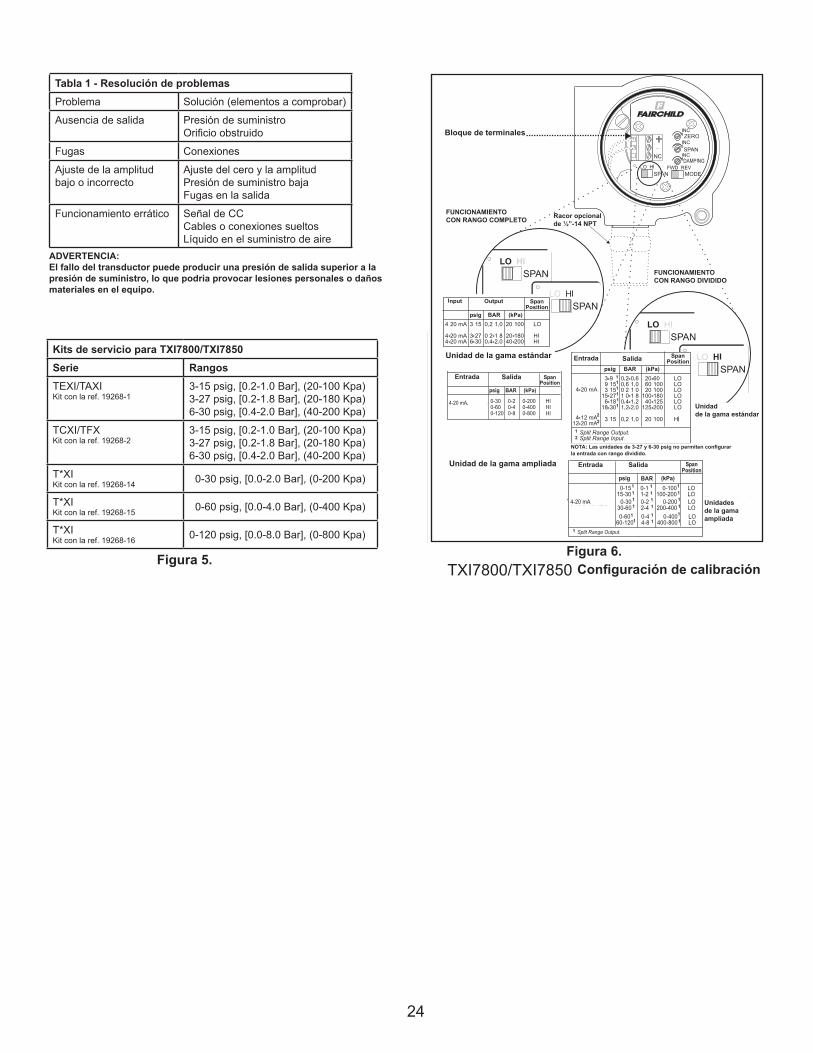
24
LEGAL NOTICE:
The information set forth in the foregoing Installation, Operation and Maintenance Instructions shall not be modified or amend-
ed in any respect without prior written consent of Fairchild Industrial Products Company. In addition, the information set forth
herein shall be furnished with each product sold incorporating Fairchild's unit as a component thereof.
IS-500TXI78
REV 08/06
Litho in USA
HAZARDOUS AREA SPECIFICATIONS
ATEX Directive Nameplates
Table 1. Trouble-Shooting
Problem Solution (check)
No Output Supply Pressure
Clogged Orifice
Leakage Connections
Low or Improper Zero and Span Adjust
Span Adjust Supply Pressure Low
Output Leakage
Erratic Operation DC Signal
Loose Wires or Connections
Liquid in Air Supply
WARNING:
Failure of Transducer could result in output pressure increasing to supply
pressure possibly causing personal injury or damage to equipment.
Figure 6.
TXI7800/TXI7850 Calibration Configuration
0-30 0-2 0-200 HI
0-60 0-4 0-400 HI
0-120 0-8 0-800 HI
Input Output
psig BAR (kPa)
4-20 mA, 0-5, 1-5,0-10 & 1-9 VDC
SpanPosition
0-15 0-1 0-100 LO15-30 1-2 100-200 LO
0-30 0-2 0-200 LO30-60 2-4 200-400 LO
0-60 0-4 0-400 LO60-120 4-8 400-800 LO
Input Output
4-20 mA, 0-5, 1-5,0-10 & 1-9 VDC
Split Range Output.
psig BAR (kPa)
1
1 1 1
1
1 1
1 1
1
1 1 1
1
1 1
1 1
1
SpanPosition
Extended
Range
Units
Standard
Range
Unit
Standard Range Unit
Extended Range Unit
Service Kits for TXI7800/TXI7850
Series Ranges
TEXI/TAXI 3-15 psig, [0.2-1.0 Bar], (20-100 Kpa)
Kit part no. 19268-1 3-27 psig, [0.2-1.8 Bar], (20-180 Kpa)
6-30 psig, [0.4-2.0 Bar], (40-200 Kpa)
TCXI/TFX 3-15 psig, [0.2-1.0 Bar], (20-100 Kpa)
Kit part no. 19268-2 3-27 psig, [0.2-1.8 Bar], (20-180 Kpa)
6-30 psig, [0.4-2.0 Bar], (40-200 Kpa)
T*XI 0-30 psig, [0.0-2.0 Bar], (0-200 Kpa)
Kit part no. 19268-14
T*XI 0-60 psig, [0.0-4.0 Bar], (0-400 Kpa)
Kit part no. 19268-15
T*XI 0-120 psig, [0.0-8.0 Bar], (0-800 Kpa)
Kit part no. 19268-16
Figure 5.
Kits de servicio para TXI7800/TXI7850Serie RangosTEXI/TAXIKit con la ref. 19268-1
3-15 psig, [0.2-1.0 Bar], (20-100 Kpa)3-27 psig, [0.2-1.8 Bar], (20-180 Kpa)6-30 psig, [0.4-2.0 Bar], (40-200 Kpa)
TCXI/TFXKit con la ref. 19268-2
3-15 psig, [0.2-1.0 Bar], (20-100 Kpa)3-27 psig, [0.2-1.8 Bar], (20-180 Kpa)6-30 psig, [0.4-2.0 Bar], (40-200 Kpa)
T*XIKit con la ref. 19268-14 0-30 psig, [0.0-2.0 Bar], (0-200 Kpa)
T*XIKit con la ref. 19268-15 0-60 psig, [0.0-4.0 Bar], (0-400 Kpa)
T*XIKit con la ref. 19268-16 0-120 psig, [0.0-8.0 Bar], (0-800 Kpa)
Figura 5. Figura 6.
Tabla 1 - Resolución de problemasProblema Solución (elementos a comprobar)
Ausencia de salida Presión de suministroOrificio obstruido
Fugas Conexiones
Ajuste de la amplitudbajo o incorrecto
Ajuste del cero y la amplitudPresión de suministro bajaFugas en la salida
Funcionamiento errático Señal de CCCables o conexiones sueltosLíquido en el suministro de aire
ADVERTENCIA:El fallo del transductor puede producir una presión de salida superior a la presión de suministro, lo que podría provocar lesiones personales o daños materiales en el equipo.
Bloque de terminales
FUNCIONAMIENTOCON RANGO COMPLETO Racor opcional
de ½”-14 NPT
FUNCIONAMIENTOCON RANGO DIVIDIDO
Unidad de la gama estándar
Unidadde la gama estándar
Unidad de la gama ampliada
Unidadesde la gamaampliada
Configuración de calibración
Entrada Salida
SalidaEntrada
Entrada Salida
NOTA: Las unidades de 3-27 y 6-30 psig no permiten configurar la entrada con rango dividido.

25
LEGAL NOTICE:
The information set forth in the foregoing Installation, Operation and Maintenance Instructions shall not be modified or amend-
ed in any respect without prior written consent of Fairchild Industrial Products Company. In addition, the information set forth
herein shall be furnished with each product sold incorporating Fairchild's unit as a component thereof.
IS-500TXI78
REV 08/06
Litho in USA
HAZARDOUS AREA SPECIFICATIONS
ATEX Directive Nameplates
Table 1. Trouble-Shooting
Problem Solution (check)
No Output Supply Pressure
Clogged Orifice
Leakage Connections
Low or Improper Zero and Span Adjust
Span Adjust Supply Pressure Low
Output Leakage
Erratic Operation DC Signal
Loose Wires or Connections
Liquid in Air Supply
WARNING:
Failure of Transducer could result in output pressure increasing to supply
pressure possibly causing personal injury or damage to equipment.
Figure 6.
TXI7800/TXI7850 Calibration Configuration
0-30 0-2 0-200 HI
0-60 0-4 0-400 HI
0-120 0-8 0-800 HI
Input Output
psig BAR (kPa)
4-20 mA, 0-5, 1-5,0-10 & 1-9 VDC
SpanPosition
0-15 0-1 0-100 LO15-30 1-2 100-200 LO
0-30 0-2 0-200 LO30-60 2-4 200-400 LO
0-60 0-4 0-400 LO60-120 4-8 400-800 LO
Input Output
4-20 mA, 0-5, 1-5,0-10 & 1-9 VDC
Split Range Output.
psig BAR (kPa)
1
1 1 1
1
1 1
1 1
1
1 1 1
1
1 1
1 1
1
SpanPosition
Extended
Range
Units
Standard
Range
Unit
Standard Range Unit
Extended Range Unit
Service Kits for TXI7800/TXI7850
Series Ranges
TEXI/TAXI 3-15 psig, [0.2-1.0 Bar], (20-100 Kpa)
Kit part no. 19268-1 3-27 psig, [0.2-1.8 Bar], (20-180 Kpa)
6-30 psig, [0.4-2.0 Bar], (40-200 Kpa)
TCXI/TFX 3-15 psig, [0.2-1.0 Bar], (20-100 Kpa)
Kit part no. 19268-2 3-27 psig, [0.2-1.8 Bar], (20-180 Kpa)
6-30 psig, [0.4-2.0 Bar], (40-200 Kpa)
T*XI 0-30 psig, [0.0-2.0 Bar], (0-200 Kpa)
Kit part no. 19268-14
T*XI 0-60 psig, [0.0-4.0 Bar], (0-400 Kpa)
Kit part no. 19268-15
T*XI 0-120 psig, [0.0-8.0 Bar], (0-800 Kpa)
Kit part no. 19268-16
Figure 5.
•Ex ia IIB T4 Ga Ex iaD 20 T90ºC Da SIRA 11ATEX2161X II 1 GD (Ta -40ºC to +80ºC) SYST DWG ED-18972 Ui=28V Ii=100mA Pi=0.7W Ci=0 Li=0
0518
CATALOG NO. TEXI78 -4 INPUT 4-20mAOUTPUTSUPPLY MAX.SUPPLY MIN. OVER MAX. OUTPUTMAXIMUM OPERATING VOLTAGE 30 VDC
Cableado en áreas peligrosasEl cableado en áreas peligrosas debe realizarse según se especifica en las tablas 3 y 4, y de acuerdo con las disposiciones legales vigentes a nivel local.
Tabla 3 - Conexiones intrínsecamente segurasOrganismo de certificación N.º de plano
FM (Factory Mutual) EC-18970
CSA (Canadian Standards Assoc.) EC-18971
ATEX EC-18972
Tabla 2 - Prácticas de cableado en áreas peligrosasPaís Organismo Normas
U.S. FM ANSI/ISA RP 12.6ANSI/NFPA70
Canada CSA CEC Part1
Europe ATEX EN 50 0392 EN 60079-14,IEC 60079-14
Global IECEx IEC 60079-14
Tabla 4 - Consumo de aire máximoConsumo de aire Punto de ajuste Unidades
30 PSIG
[2.0] [BAR]
(200) (kPa)
SCFH/(m3/Hr) 13.5/(0.38)
ESPECIFICACIONES PARA ÁREAS PELIGROSASPlacas de características según la Directiva ATEX
IS-500TXI78REV A 05/16Litho in USA
ISO 9001:2008Certified
Fairchild Industrial Products Company3920 West Point Blvd • Winston-Salem, NC 27103phone: (336) 659-3400 • fax: (336) [email protected] • www.fairchildproducts.com
prec is ion pneumat ic & mot ion contro l
La información contenida en la anterior instalación, instrucciones de operación y mantenimiento no será modificada o enmendada en cualquier sentido sin el previo consentimiento por escrito de la compañía Industrial de productos de Fairchild. Además, se aportará la información establecida con cada producto que vende unidad de Fairchild incorpora como un componente del mismo.
AVISO LEGAL:
Ubicación peligrosa instalación: Advertencias y condiciones especiales de instalación y usoEl gabinete es fabricado de aleación de aluminio. En casos raros, fuentes de ignición por chispas impacto y fricción podrían ocurrir. Esto se considerará cuando el equipo se instala en ubicaciones que específicamente requieren grupo II, categoría 1G o clase I, División 1 equipo.
CSA Instalaciones de la casa para la Clase I, División 1 Grupo D con el gas como elementos principales de la presión de alimentación deben instalarse con una opción de drenaje roscado, o el cliente deberá permitir la evacuación de la zona clasificada, en base a la velocidad de purga y el número de unidades en funcionamiento. La tasa de flujo de purga proporcionada en la tabla para la unidad es el ajuste máximo de 30 PSIG de salida, independientemente de la presión de alimentación a un máximo de 125 PSIG.