fairbanksŠ north pole realignment€¦ · the alaska railroad mainline includes approximately 500...
TRANSCRIPT

FAIRBANKS�NORTH POLE REALIGNMENTPhase III Technical Analysis
May 2007

Alaska Railroad Corporation 327 West Ship Creek Avenue Anchorage, Alaska 99501
FAIRBANKS�NORTH POLE REALIGNMENT
Phase III Technical Analysis
May 2007
Prepared by
Submitted by
Norman K. Gutcher, PE Project Manager
In association with

FAIRBANKS—NORTH POLE REALIGNMENT PHASE III TECHNICAL ANALYSIS
TNH 04071.002 Page i of vii May 2007
TABLE OF CONTENTS
Page
Executive Summary ......................................................................................... iii
1. Introduction............................................................................................. 1
1.1 Background..............................................................................................................1
1.2 Study Purpose ..........................................................................................................3
1.3 Study Objectives ......................................................................................................3
2. Analysis .................................................................................................. 4
2.1 Study Area ...............................................................................................................4
2.2 Alternates .................................................................................................................42.2.1 Parks Highway Alternate .............................................................................4 2.2.2 Chena Pump Alternate .................................................................................5
2.2.2.1 Option 1 .....................................................................................5 2.2.2.2 Option 2 .....................................................................................6 2.2.2.3 Both Options ..............................................................................6
2.2.3 Trainor Gate Alternate .................................................................................6
2.3 Design Criteria.........................................................................................................7 2.3.1 Roadway ......................................................................................................7 2.3.2 Railway ........................................................................................................8 2.3.3 Typical .........................................................................................................9
2.4 Discussion of Alternates ........................................................................................11 2.4.1 Parks Highway Alternate ...........................................................................11 2.4.2 Chena Pump Alternate ...............................................................................23
2.4.2.1 Option 1 ...................................................................................25 2.4.2.2 Option 2 ...................................................................................27
2.4.3 Trainor Gate Alternate ...............................................................................31
2.5 Impacts...................................................................................................................352.5.1 Operational Issues......................................................................................35
2.5.1.1 Railroad....................................................................................35 2.5.1.2 Highway...................................................................................36 2.5.1.3 Airport......................................................................................37 2.5.1.4 Chena River .............................................................................37
2.5.2 Community and Environmental Issues ......................................................38
2.6 Public Process ........................................................................................................39
3 Summary............................................................................................... 40

FAIRBANKS—NORTH POLE REALIGNMENT PHASE III TECHNICAL ANALYSIS
TNH 04071.002 Page ii of vii May 2007
TABLES
Table 1A Roadway Design Criteria – All Alternates ..............................................................8
Table 1B Railway Design Criteria – All Alternates ................................................................9
Table 2A Bridge Summary – Parks Highway .......................................................................18
Table 2Bi Bridge Summary – Chena Pump, Option 1 ...........................................................26
Table 2Bii Bridge Summary – Chena Pump, Option 2 ...........................................................29
Table 2C Bridge Summary – Trainor Gate ...........................................................................34
Table 3A Construction Summary – Parks Highway..............................................................19
Table 3Bi Construction Summary – Chena Pump, Option 1..................................................27
Table 3Bii Construction Summary – Chena Pump, Option 2..................................................30
Table 3C Construction Summary – Trainor Gate..................................................................34
Table 4 Potential Impacts – All Alternates .........................................................................38
APPENDICES
Appendix A Typical Maps
Appendix B Typical Sections
Appendix C Parks Highway
Appendix D Chena Pump
Appendix E Trainor Gate
Appendix F Department of Transportation Letters

FAIRBANKS—NORTH POLE REALIGNMENT PHASE III TECHNICAL ANALYSIS
TNH 04071.002 Page iii of vii May 2007
EXECUTIVE SUMMARY
The Alaska Railroad mainline includes approximately 500 miles of track. The mainline is
currently considered to terminate at the Fairbanks yards. Local freight service in the Fairbanks area
is provided by the Airport Branch serving the airport and the industrial area of South Fairbanks.
Service to Fort Wainwright, Eielson Air Force Base, North Pole and the North Pole Refinery is
provided by the Eielson Branch. According to the report prepared by the Fairbanks North Star
Borough (FNSB) Rail 2100 Task Force, some 45 percent of Alaska Railroad rail traffic moves
through the Fairbanks Terminal.
The Alaska Railroad and the City of Fairbanks have coexisted for over 80 years. During
that time, the City has grown from a trading post into a city that serves as the transportation and
business hub for interior Alaska. The growth of this urban area has brought a corresponding
expansion of the system of streets and highways and significant growth in vehicular traffic. Today,
according to the Alaska Railroad Corporation (ARRC) Track Charts, there are approximately 52
public at-grade road/rail crossings within the most densely populated core area in and around
Fairbanks. As trains move through the urban area there are two significant concerns: 1) the
potential for train/vehicle collisions increasing is a very real safety concern; and 2) traffic
congestion resulting from vehicles waiting for slow moving trains to clear the crossings. This
contributes to considerable delay and to degradation of air quality. The mix of continued rail traffic
and slow but steady growth in vehicle traffic throughout the urban area will only aggravate the
issues of safety and congestion, unless action is taken to address the problem.
ARRC and the Fairbanks community have been working to identify potential solutions to
the train/vehicle conflicts. Since 2000, at least three studies have been done:
¶ Fairbanks Bypass Realignment Reconnaissance, January 2001 prepared by Thomas
Engineering in association with Peratrovich, Nottingham & Drage, Inc. for ARRC.
¶ Fairbanks to North Pole Realignment Project Phasing Report, March 2002 prepared
by Thomas Engineering in association with Peratrovich, Nottingham & Drage, Inc.
for ARRC.

FAIRBANKS—NORTH POLE REALIGNMENT PHASE III TECHNICAL ANALYSIS
TNH 04071.002 Page iv of vii May 2007
¶ Rail Realignment and Extension Planning Report, March 2004 prepared by the FNSB
Rail 2100 Task Force. (Not an adopted document)
The Fairbanks—North Pole Realignment, Phase II Technical Analysis presents a more in-
depth look at the technical aspects of three of the most viable of the alternates presented in the
reports listed above.
Study Purpose—At this time all of the rail traffic moving through the Fairbanks urban
area is in direct conflict with the vehicular traffic using the Fairbanks streets and highways because
of the 52 at-grade crossings, also mentioned above. Many of these involve high volume arterials
and collectors. The mix of rail traffic integrating with vehicular traffic is a very real safety concern
for the community due to the potential for motor vehicle/train collisions. This potential steadily
increases as the greater Fairbanks area continues to grow with the resulting increases in vehicular
traffic. The congestion that comes from the vehicles waiting for trains results in an accumulated
delay that translates to a significant cost to the motoring public.
The purpose of this technical report is to provide information that can be used to assess the
technical feasibility of realigning a portion of the ARRC’s freight line to eliminate many of the at-
grade rail crossings in and around the Fairbanks area as a way to improve traffic safety and reduce
the traffic congestion resulting from rail operations. Of the several alternatives addressed by
Thomas Engineering and the FNSB 2100 Task Force, there are three realignment concepts that
appear to have the most promise. The three alternatives reviewed are:
1. The Parks Highway Alternate
2. The Chena Pump Alternate
3. The Trainor Gate Alternate
The Parks Highway Alternate—The Parks Highway Alternate begins on the mainline
near the Sheep Creek Connector. The alignment quickly diverges southeast away from the
mainline to merge with the Parks Highway. It then passes under realigned west bound (WB) lanes
of the Parks Highway to occupy the Parks Highway median for ± 2.45 miles passing immediately
east of the Fairbanks International Airport and at an elevation that is safely below the obstruction

FAIRBANKS—NORTH POLE REALIGNMENT PHASE III TECHNICAL ANALYSIS
TNH 04071.002 Page v of vii May 2007
free surfaces for the airport. The alignment then leaves the Parks Highway median, passing under
newly reconstructed east bound (EB) lanes and turning south to link east and west with the Airport
Spur and extend on the Tanana River Levee system. Upon reaching the levee, the alignment turns
and travels easterly along the Tanana River levee coincident with the Chena Pump Alternate.
The Parks Highway Alternate clearly meets the goals of the project in that many of the at-
grade crossings in the urban area are eliminated resulting in improved traffic safety and reduced
congestion. The alternate will also have impacts that must be considered, including:
¶ Reconstruction of half of the Parks Highway for ± 2.5 miles
¶ Acquisition of ± 65 parcels
¶ Impact on ± 93.5 acres of wetlands
¶ Snow removal and snow storage concerns for ARRC and ADOT&PF
¶ Incident management concerns for ARRC
¶ Maintenance access concerns for ARRC
The Chena Pump Alternate—The Chena Pump Alternate has two options. Both begin at
the western limit near the Sheep Creek Connector, and through development of a new line change
routing, cross under the Parks Highway moving south through the Chena Pump Road/Chena Ridge
area. The basic difference between options 1 and 2 is that Option 2 moves further southwest along
the toe of Chena Ridge before turning east to rejoin Option 1. Option 2 is 6,300 feet. (1.19 miles)
longer that Option 1. Both options traverse an area currently developing as a relatively new “high
end” residential neighborhood. The alignments have been selected to avoid currently existing
homes; however, development continues in this area. Both alignments cross the Chena River and
require a movable span bridge to accommodate operations of a tourist attraction river boat. The
two options rejoin and follow the Tanana River levee system to near the east end of the south
Fairbanks industrial area, where the alignment turns north to join the Airport Branch and
ultimately crosses the Richardson Highway to rejoin the Eielson Branch near Badger Road. It
should be noted that the Parks Highway Alternate is coincident with the Chena Pump Alternate
from just west of Peger Road to the end.

FAIRBANKS—NORTH POLE REALIGNMENT PHASE III TECHNICAL ANALYSIS
TNH 04071.002 Page vi of vii May 2007
The Chena Pump Alternate clearly meets the goals of the project in that many of the at-
grade crossings in the urban area are eliminated resulting in improved traffic safety and reduced
congestion. The alternate will also have impacts that must be considered including:
¶ Acquisition of ± 102 parcels with Option 1 or ± 115 parcels with Option 2
¶ Impact on ± 93.2 acres of wetlands with Option 1, and ± 129.5 acres of wetlands with
Option 2
¶ This alternate does not have the snow removal and snow storage concerns for ARRC
and ADOT&PF that the Parks Highway Alternate has
¶ This alternate introduces a new major transportation corridor into a developing
neighborhood
The Trainor Gate Alternate—This alternate again begins near the Sheep Creek
connector; however, considerably more of the existing mainline track is included in the Alternate
without reconstruction. The Alaska Department of Transportation and Public Facilities
(ADOT&PF) is currently moving forward with a project to construct a grade separated crossing at
University Avenue that can, in some ways, be considered a first phase of this alternate. The
primary work of this alternate is a change in grade of the ARRC’s Eielson Branch between the
Fairbanks yard and Fort Wainwright. This work is expected to begin approximately 1.1 miles west
of the College Road grade crossing, and will extend to the east along the Railroad’s Eielson
Branch for a distance of ± 3.9 miles, just into Fort Wainwright, where it will connect with the Fort
Wainwright realignment project. A new bridge over Noyes Slough will be required and the profile
will be elevated a sufficient height to provide clearance for installation of grade separation
structures at the site of the following existing railroad/roadway grade crossings.
¶ College Road
¶ A future Farmer’s Loop Connector
¶ Old Steese Highway
¶ Steese Expressway

FAIRBANKS—NORTH POLE REALIGNMENT PHASE III TECHNICAL ANALYSIS
TNH 04071.002 Page vii of vii May 2007
¶ Blair Road
¶ D Street
¶ F Street
¶ A future extension of G Street
The Trainor Gate Alternate clearly meets the goals of the project in that many of the at-
grade crossings in the urban area are eliminated resulting in improved traffic safety and reduced
congestion. This alternate does not require acquisition of additional right-of-way (ROW) nor does
it impact wetlands. It may also have impacts such as:
¶ This alternate does have snow removal and snow storage concerns for ARRC and the
City of Fairbanks, somewhat similar to those associates with the Parks Highway
Alternate.
¶ This alternate has some of the incident management and maintenance concerns that the
Parks Highway alternate has due to the restricted access associated with the elevated
track.
¶ This alternate introduces a 20+ foot high embankment where there currently is none. It
is this embankment; however, that provides the resulting improved vehicular and
pedestrian safety.
Conclusion—Each of the three alternates evaluated in this report meet the stated goals of
improving traffic safety and reducing congestion by eliminating at-grade crossings throughout the
Fairbanks urban area. Each of the alternates also has potential drawbacks in terms of construction
impacts, environmental impacts, operational considerations for the ARRC, ADOT&PF, the
Borough and/or the City.
This report does not include a recommendation as to a preferred alternate. Rather, it is
intended to provide data relative to each of the three alternates that should be useful to the decision
makers in determining how to move forward in addressing the traffic safety and congestion issues
in the Fairbanks urban area.

FAIRBANKS—NORTH POLE REALIGNMENT PHASE III TECHNICAL ANALYSIS
TNH 04071.002 Page 1 of 42 May 2007
1. INTRODUCTION
1.1. Background
The community of Fairbanks began in 1901 with the establishment of a trading post by E.
T. Barnette. Native Alaskans have lived in the Fairbanks area for thousands of years. Miners had
been actively searching for gold in the area for several years, and in 1902, Felix Pedro discovered
it. With this discovery and the resulting frantic activity, a new city grew up around Barnette's
trading post and was incorporated in 1903.
Today, the City of Fairbanks (COF) is the population center of the Fairbanks North Star
Borough (FNSB), and the economic center of interior Alaska. The population of the FNSB,
according to the COF website, is approaching 85,000. Well over half of this population is
concentrated in the 25-plus miles from west of the Fairbanks/Fort Wainwright area to, and
including, North Pole and Eielson Air Force Base (AFB). The primary economic influences
include the University of Alaska Fairbanks (UAF), Fort Wainwright, Eielson AFB, the North Pole
(Flint Hills) refinery, the Fort Knox Gold Mine and the tourism industry.
Fairbanks was a major support center during construction of the Trans-Alaska Pipeline, and
continues as a logistic support center for North Slope exploration and development activities. It is
expected that Fairbanks will again be a major activity center should a major natural gas pipeline
project come to fruition. The continued growth and success of these economic engines translates
into population growth which, in turn, translates to growth in traffic volumes on the FNSB
roadways, and more importantly, growth in vehicle miles traveled across the urban area.
The Alaska Railroad began as two independent, privately owned railroads, the Tanana
Valley Railroad and the Alaska Central Railroad. Federal legislation in 1914 authorized the
construction of up to 1,000 miles of track in Alaska. The Alaska Engineering Commission
subsequently purchased the Alaska Central and Tanana Valley lines and completed the
construction of track, connecting track already constructed by these two lines, to complete the
track from Seward to Fairbanks in 1923.

FAIRBANKS—NORTH POLE REALIGNMENT PHASE III TECHNICAL ANALYSIS
TNH 04071.002 Page 2 of 42 May 2007
The Alaska Railroad mainline includes about 500 miles of track and is currently considered
to terminate at the Fairbanks yards. Local freight service in the Fairbanks area is provided by the
Airport Branch serving the airport and the industrial area of South Fairbanks. Service to Fort
Wainwright, Eielson AFB, North Pole and the North Pole Refinery is provided by the Eielson
Branch. According to the report prepared by the FNSB Rail 2100 Task Force, some 45 percent of
the Alaska Railroad rail traffic moves through the Fairbanks Terminal. According to the ARRC
Track Charts, there are approximately 52 public at-grade road/rail crossings within the most
densely populated core area in and around Fairbanks. As trains move through the urban area there
are two significant concerns: 1) the potential for train/vehicle collisions increasing is a very real
safety concern; and 2) traffic congestion resulting from vehicles waiting for slow moving trains to
clear the crossings. This contributes to considerable delay and to degradation of air quality. The
mix of continued rail traffic and slow but steady growth in vehicle traffic throughout the urban
area will only aggravate the issues of safety and congestion, unless action is taken to address the
problem.
The Alaska Railroad Corporation (ARRC) and the Fairbanks community have been
working to identify potential solutions to the train/vehicle conflicts. Since 2000, at least three
studies have been done:
¶ Fairbanks Bypass Realignment Reconnaissance, January 2001 prepared by Thomas
Engineering in association with Peratrovich, Nottingham & Drage, Inc. for ARRC.
¶ Fairbanks to North Pole Realignment Project Phasing Report, March 2002 prepared by
Thomas Engineering in association with Peratrovich, Nottingham & Drage, Inc for
ARRC.
¶ Rail Realignment and Extension Planning Report, March 2004 prepared by the FNSB
Rail 2100 Task Force.
The analyses below presents a more in-depth look at the technical aspects of three of the
most viable of the alternates presented in the reports listed above.

FAIRBANKS—NORTH POLE REALIGNMENT PHASE III TECHNICAL ANALYSIS
TNH 04071.002 Page 3 of 42 May 2007
1.2. Study Purpose
As stated above, it has been estimated that approximately 45 percent of the freight moved
on the Alaska Railroad moves through the Fairbanks urban area. At this time, all of that rail traffic
is in direct conflict with the vehicular traffic using the Fairbanks streets and highways because of
the 52 at-grade crossings, also mentioned above. Many of the at-grade crossings involve high
volume arterials and collectors. The mix of rail traffic integrating with vehicular traffic is a very
real safety concern for the community, due to the potential for motor vehicle/train collisions at the
crossings. This potential steadily increases as the greater Fairbanks area continues to grow,
resulting in increases in vehicular traffic. In addition, the accumulated delay, resulting in very
significant local congestion for vehicular traffic as a result of rail traffic, is a significant cost to the
motoring public.
The purpose of this study effort is to provide information that can be used to assess the
technical feasibility of realigning a portion of the ARRC’s freight line to eliminate many of the at-
grade rail crossings in and around the Fairbanks area, as a way to improve traffic safety and reduce
the traffic congestion resulting from rail operations. Of the several alternatives addressed by
Thomas Engineering and the FNSB 2100 Task Force, there are three realignment concepts that
appear to have the most promise. These alternates: 1) the Parks Highway Alternate, 2) the Chena
Pump Alternate and, 3) the Trainor Gate Alternate, are fully addressed below. ARRC may
determine that currently unforeseen factors may prompt examination of additional alternatives as
the project progresses.
1.3. Study Objectives
The primary objective of this analysis and report is to provide the ARRC, the Alaska
Department of Transportation and Public Facilities (ADOT&PF), the City of Fairbanks (COF), the
Fairbanks North Star Borough (FNSB), community leaders, and the citizens in Fairbanks the data
necessary to evaluate potential infrastructure modifications that may result from realignment of the
ARRC facilities. To do this, the strengths and weaknesses of each of the three realignment
concepts will be discussed.

FAIRBANKS—NORTH POLE REALIGNMENT PHASE III TECHNICAL ANALYSIS
TNH 04071.002 Page 4 of 42 May 2007
2. ANALYSIS
2.1 Study Area
On a gross scale, the study area encompasses the majority of the City of Fairbanks. For the
purpose of this report, all three alternates presented herein begin at Railroad Mile Post 465.47, near
the Sheep Creek Connector, and extend south and east through the urban area to rejoin the existing
Eielson Branch Line near the east side of Fort Wainwright in the vicinity of Badger Road. Three
basic alignment alternates were evaluated and are identified as 1) Parks Highway; 2) Chena Pump
(including two options); and 3) Trainor Gate. They follow substantially different alignments and
present substantially different challenges and opportunities. It should be noted that the eastern
portions of the Parks Highway and Chena Pump Alternates are coincident. The differences
between these alternates derive from the routing around Fairbanks International Airport (FIA).
2.2 Alternates
2.2.1 Parks Highway Alternate
The Parks Highway Alternate begins near the Sheep Creek Connector (Sta.
138+45), and, utilizing development of new line change routing, diverges southeast away
from the existing mainline track towards the Parks Highway. Near Sta. 158+00, the
alignment passes under the realigned westbound (WB) lanes of the Parks Highway to join
the highway median at Sta. 171+38 ±. From that point, the Alternate travels within the
Parks Highway median in a generally southeast direction, passing immediately east of FIA
at an elevation that is safely below the obstruction-free surfaces for the airport (Sta. 475+00
±). (This stationing includes an equation station 208+90.30 Bk = 382+19.23 Ahd.) The
alignment leaves the Parks Highway median at this point, passing under newly
reconstructed EB lanes and turning south to link east and west with the Airport Spur and
extend on the Tanana River Levee system (Sta. 562+43). Upon reaching the levee, the
alignment turns and travels easterly along the Tanana River levee, joining with the Chena
Pump Alternate. The length of rail realignment from the beginning of project to the
connection at the Tanana River is 25,070 feet, or 4.75 miles. The length of this alternate is

FAIRBANKS—NORTH POLE REALIGNMENT PHASE III TECHNICAL ANALYSIS
TNH 04071.002 Page 5 of 42 May 2007
coincident with the Chena Pump Alternate along the Tanana Levee system, for an
additional distance of 26,300 feet or 4.98 miles.
2.2.2 Chena Pump Alternate
The Chena Pump Alternate has two options, which are laid out in Appendices D-4
through D-10. Both begin, at the western limit, near the Sheep Creek Connector (Sta.
95+52) and, through development of a new line change routing, cross under the Parks
Highway at an angle of approximately 45º and move south through the Chena Pump
Road/Chena Ridge area. The length of rail realignment considered herein is 67,700 feet or
12.82 miles for Option 1 and 73,300 feet or 13.88 miles for Option 2. Typical sections are
shown in Appendices D-1 through D-3.
2.2.2.1 Option 1
After crossing the Parks Highway, Option 1 moves south, essentially parallel to
Chena Pump Road for about a mile, to Old Chena Ridge Road (Sta. 198+54) then cuts west
briefly (± ½ mile) before turning south for nearly 3 miles, where it turns east to cross the
Chena river south of FIA at Sta. 310+86. After crossing the Chena River, Option 1
continues south, beginning a turn to the east at Sta. 351+00 ± and joining the Tanana River
Levee system at Sta. 378+20 ±. Here, the Option traverses more or less along the Tanana
River levee alignment until it reaches a point (Sta. 731+ 50 ±) where it turns north to
connect into the existing north/south portion of the Airport Spur (Sta. 785+82), and
continues to the end of the existing Airport Spur. From this point, the new option will
extend north, passing under the Parks Highway and connecting north and east with the
Eielson Branch in the vicinity of Badger Road. After turning north off of the Tanana River
Levee, Option 1 follows the concept presented in the “Fairbanks to North Pole
Realignment Project Phasing Report”, March 2002 by Thomas Engineering. ARRC has
determined that additional study of this segment is not required as a part of this study
effort.

FAIRBANKS—NORTH POLE REALIGNMENT PHASE III TECHNICAL ANALYSIS
TNH 04071.002 Page 6 of 42 May 2007
2.2.2.2 Option 2
Option 2 is nearly the same as Option 1, except that in the Chena Ridge area, it
extends further to the southwest before turning east, between homes and the Tanana River,
to cross over the Chena River and rejoin the Option 1 alignment. Option 2 is approximately
6,300 feet or 1.2 miles longer than Option 1.
2.2.2.3 Both Options
Both options are routed deliberately through as much vacant land as possible to
avoid displacing homes through the ROW process. Property impacts are shown in
Appendices D-11 through D-14. None the less, both Options take a new major rail corridor
through the middle of a cohesive and developing residential community. In addition, both
Options cross the Chena River in its lower reaches. The challenge here is the operation of a
river tour boat, which is centered around an old stern- style wheel river boat such as
traveled the inland river system for many years. This vessel is tall enough that the crossings
of the Chena would require 1) a grade raise that would allow crossing of the Chena with at
least 50 foot clearance during near bank full stream flows; or 2) a movable or lift span
bridge that would provide sufficient waterway opening for river boat operations. For the
purposes of this analysis, it is assumed a moveable span bridge would be used, requiring
critical coordination between ARRC and the river boat operator.
2.2.3 Trainor Gate Alternate
This alternate also begins near the Sheep Creek Connector; however, considerably
more of the existing mainline track is included in the Alternate without reconstruction.
ADOT&PF is currently moving forward with a project to construct a grade-separated
crossing at University Avenue that can, in some ways, be considered a first phase of this
Alternate. The primary work of this Alternate is a reprofiling of the ARRC’s Eielson
Branch. This work is expected to begin 5,950 feet or 1.13 miles west of the College Road
grade crossing, and will extend to the east along the railroad’s Eielson Branch for a
distance of 20,800 feet or 3.94 miles. An overview is shown in Appendices E-1 and E-2. A

FAIRBANKS—NORTH POLE REALIGNMENT PHASE III TECHNICAL ANALYSIS
TNH 04071.002 Page 7 of 42 May 2007
new bridge over Noyes Slough will be required, and the profile will be elevated a sufficient
height to provide clearance for installation of grade separation structures at the site of the
following existing railroad/roadway grade crossings:
¶ College Road
¶ Old Steese Highway
¶ Steese Expressway
¶ D Street
¶ F Street
¶ A future extension of G Street
After crossing the future G Street, the profile returns to existing ground elevation
and continues on as the planned realignment of the Eielson Branch line through Fort
Wainwright.
2.3 Design Criteria
Coordination with ARRC and ADOT&PF has been conducted to determine design criteria
applicable to both rail and road facilities. Rail criteria conform to ARRC standards supplemented
with information provided by the American Railway Engineering and Maintenance of Way
Association (AREMA). Roadway design meets the requirements set forth in ADOT&PF’s
Highway Preconstruction Manual and the American Association of State Highways and
Transportation Officials (AASHTO) Roadway Design Guide. In all cases, the most recent
standards have been followed.
2.3.1 Roadway
Road/Highway design criteria are normally based on Average Annual Daily Traffic
(AADT and facility classification). The streets and highways potentially impacted by any
of the alternates under consideration include local streets, urban collectors, arterials and
freeways. The critical impact, however, will be to the freeways and the arterial/collector
FAIRBANKS—NORTH POLE REALIGNMENT PHASE III TECHNICAL ANALYSIS
TNH 04071.002 Page 8 of 42 May 2007
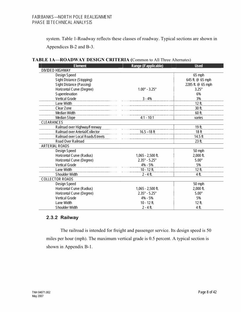
system. Table 1-Roadway reflects these classes of roadway. Typical sections are shown in
Appendices B-2 and B-3.
TABLE 1A—ROADWAY DESIGN CRITERIA (Common to All Three Alternates) Element Range (if applicable) Used
DIVIDED HIGHWAY Design Speed 65 mph Sight Distance (Stopping) 645 ft. @ 65 mph Sight Distance (Passing) 2285 ft. @ 65 mph Horizontal Curve (Degree) 1.00° - 3.25° 3.25° Superelevation 6% Vertical Grade 3 - 4% 3% Lane Width 12 ft. Clear Zone 30 ft. Median Width 60 ft. Median Slope 4:1 - 10:1 varies
CLEARANCES Railroad over Highway/Freeway 19 ft. Railroad over Arterial/Collector 16.5 –18 ft 18 ft Railroad over Local Roads/Streets 14.5 ft Road Over Railroad 23 ft.
ARTERIAL ROADS Design Speed 50 mph Horizontal Curve (Radius) 1,065 - 2,500 ft. 2,000 ft. Horizontal Curve (Degree) 2.35° - 5.25° 5.00° Vertical Grade 4% - 5% 5% Lane Width 10 - 12 ft. 12 ft. Shoulder Width 2 - 4 ft. 4 ft.
COLLECTOR ROADS Design Speed 50 mph Horizontal Curve (Radius) 1,065 - 2,500 ft. 2,000 ft. Horizontal Curve (Degree) 2.35° - 5.25° 5.00° Vertical Grade 4% - 5% 5% Lane Width 10 - 12 ft. 12 ft. Shoulder Width 2 - 4 ft. 4 ft.
2.3.2 Railway
The railroad is intended for freight and passenger service. Its design speed is 50
miles per hour (mph). The maximum vertical grade is 0.5 percent. A typical section is
shown in Appendix B-1.

FAIRBANKS—NORTH POLE REALIGNMENT PHASE III TECHNICAL ANALYSIS
TNH 04071.002 Page 9 of 42 May 2007
TABLE 1B—RAILWAY DESIGN CRITERIA (Common to All Three Alternatives) Element Range (if applicable) Used
RAILROADDesign Speed 50 mph Rail Classification ARRC Standard Sub ballast Half-Crown Width 12 ft. Spacing Between Double Tracks 16 ft. Horizontal Clearance (Minimum) 9 ft. Railroad over Highway/Freeway 19 ft. Railroad over Arterial/Collector 16.5 –18 ft 18 ft Railroad over Local Roads/Streets 14.5 ft Road Over Railroad 23 ft. Vertical Grade (Maximum) 0.5 % Maximum Horizontal Curvature 3°15' * Eu (Unbalanced Super) 2"Ea (Maximum Actual Super) 4"Vertical Curve (Minimum length) L=V2D(2.15)/0.1
* 4°30' is proposed on the Trainor Gate Alternative to match curvature on west end of the future Eielson Branch Realignment project.
2.3.3 Typical
ARRC may operate trains approaching 8,000 feet in length from North Pole. Slack
action associated with railroad equipment necessitates changes in railroad grades be limited
to no more than one each ascending and descending per train length.
Typical sections have been developed for both roadway and rail construction as
discussed below.
Railway typical sections for track construction have been developed beginning with
the standard ARRC grading section to provide for an initial double-track construction. This
standard typical section has been modified to reflect the various conditions that may be
encountered should any of these alternates be implemented. These modifications may
include provisions of additional width to accommodate maintenance access, and, if
required, a future second main track. Where retaining walls may be required, such as along
Trainor Gate Road, the proposed sections reflect the site-specific conditions, as reflected in
Appendices E-3 through E-5.

FAIRBANKS—NORTH POLE REALIGNMENT PHASE III TECHNICAL ANALYSIS
TNH 04071.002 Page 10 of 42 May 2007
Parks Highway/Railroad Alignment typical section development is a blend of the
typical sections appropriate to each transportation mode. One of the attractions of placing
the proposed railroad alignment within in the median of the existing Parks Highway system
is that it offers the potential of using existing public right-of-way for development of the
rail system. This would theoretically reduce the property acquisition impacts normally
associated with constructing a new railroad alignment.
In order for this approach to avoid relocation of existing Parks Highway
infrastructure, it is necessary that the grading and bridge structures for the proposed
alignment be constructed without encroaching on existing Parks Highway pavement, road
overpasses and stream crossing structures. Doing so however, requires placing the railroad
in the highway median. The median was designed as a “clear zone”, normally required for
highway safety and which, in northern climates, doubles as area for snow storage. Both
functions are considered critical to highway operations.
The proposed railroad alignment cannot utilize grades as steep as the existing Parks
Highway grades, and must also maintain longer distances between breaks in profile grade
(a minimum of 8,000 feet) that cause reverses in gradient direction. This difference in
operation criteria requires that the railroad grade be raised more than twenty feet over the
existing highway grade. Side slopes on such a high earthen fill height would spill over onto
the existing pavement, consequently requiring that the railroad alignment be supported on
retaining walls for most of its length within the Parks Highway median.
Various retaining wall sections were developed for support of the elevated Parks
Highway track profile. The intent of the various retaining wall sections was to minimize
project impacts on vehicular traffic and the existing Parks Highway infrastructure, and
simultaneously to satisfy the requisite rail alignment design criteria for alignment, profile
and future capacity.

FAIRBANKS—NORTH POLE REALIGNMENT PHASE III TECHNICAL ANALYSIS
TNH 04071.002 Page 11 of 42 May 2007
2.4 Discussion of Alternates
2.4.1 Parks Highway Alternate
Alternative Concepts
The original concept for using the median of the Parks Highway for a rail
alignment, the “Median” alternate was first presented in the “Fairbanks Bypass
Realignment Reconnaissance” dated January 2001 by Thomas Engineering. That concept
envisioned a single track option constructed in the Parks Highway median on retained earth
embankment. As proposed by Thomas Engineering, the construction would have occupied
most of the highway median currently used by ADOT&PF for snow storage and clear zone.
The profile grade proposed by Thomas tended to follow the variation is ground elevations
and included quite a number of crest and sag vertical curves resulting in what can best be
described as a “bumpy” profile by railroad standards.
The study team was originally tasked by ARRC with determining the extent of
construction that would be necessary to place a rail facility in the highway median that
would both meet the ARRC design criteria and; determine the highway modifications that
would be necessary to enable the Parks Highway to continue to meet ADOT&PF and
FHWA design criteria.
Public comment received during the study asked about three additional options for
adding rail to the Parks Hwy corridor:
¶ Elevated but on a structure using a “Hammerhead” style pier
¶ Parallel but to the east side of the Parks Highway
¶ Use of a tunnel as opposed to being elevated
Each of these alternative concepts will be addressed below, beginning with the
“Median” or original concept as suggested in the Thomas Engineering report.

FAIRBANKS—NORTH POLE REALIGNMENT PHASE III TECHNICAL ANALYSIS
TNH 04071.002 Page 12 of 42 May 2007
The “Median” Option—As mentioned previously, the west end of this alternate is
at Mile 465.47 near the Sheep Creek Road Connector. It then bends southeast into the
median of the Parks Highway and stays within the median to a point roughly one (1) mile
north of the Tanana River. From there, the route is due south to the levee along the north
side of the river.
Field investigations have been performed to better characterize this Alternate. Five
impact categories were considered: Utilities, Geometrics, Structural, Environmental, and
Airport. Observations for each category are provided below. In general, the discussion
flows from the north end to the south and southeast. An overall Construction Summary is
provided in Table 3A.
Utilities
This alternate may impact numerous utilities depending upon the final design.
Major utilities include the two Golden Valley Electrical Association (GVEA) lines near the
beginning of the project and the power line across the Chena River. In each case,
depending on the final profile grade, it may be necessary to raise or otherwise relocate the
utility.
Parks Highway at UAF
¶ 1 – 138 kV Transmission Line
¶ 2 – 69 kV Transmission Line
¶ 1 – 7.2 kV Local Distribution Line
Parks Highway at Trinidad Drive
¶ 1 – 7.2 kV Local Distribution Line
Parks Highway at Chena River
¶ 1 – 69 kV Transmission Line
FAIRBANKS—NORTH POLE REALIGNMENT PHASE III TECHNICAL ANALYSIS
TNH 04071.002 Page 13 of 42 May 2007
Parks Highway at University Avenue
¶ 1 – 138 kV Transmission Line
¶ 1 – 69 kV Transmission Line
Cartwright Road
¶ 1 – 7.2 kV Local Distribution Line
The clearance from top of rail (TOR) to the lowest part of the sag in an electrical
line is calculated for the warmest days of the year, when the sag is at its greatest. For the
138 kV lines this clearance, according to the AREMA, the clearance criteria is ± 38 feet.
The existing power line structures are timber construction. It will not be practical to
attempt to raise these existing structures; rather, a new structure will be needed on either
side of the crossing that is tall enough to provide the needed clearance. When this is done,
the next structures in line may have to be replaced as well to avoid subjecting them to loads
vastly different than the loads they were designed to accommodate. In addition, to provide
the necessary length of cable to accommodate the taller structures, a section of the line may
have to be re-conductored. If raising the elevation of the 138 kV Transmission Line at
either location is not practical, than rerouting may be necessary; raising the elevation of the
conductor is typically the more cost effective solution. Placing 138 kV Transmission Lines
underground is not normally done if there are above-ground options available.
The required clearance between TOR and the conductor sag is, to some extent, a
function of the operating voltage of the electrical lines. Therefore, the clearance required
for the 69 kV crossings will be a bit less. With the lower voltage, placing the electrical
lines underground becomes an option, subject to negotiations with GVEA. If possible, the
more cost effective method of adjusting the 69 kV lines will be to replace the adjacent pole
structures with taller poles and splice in an additional length of conductor. It should also be
possible to bring the 69 kV lines into a concrete encased underground conduit for the
crossings, if raising the lines is not practical.
When local distribution lines, such as the 7.2 kV lines are encountered, it may be
just as simple to put them underground in a conduit for the crossing.

FAIRBANKS—NORTH POLE REALIGNMENT PHASE III TECHNICAL ANALYSIS
TNH 04071.002 Page 14 of 42 May 2007
It should also be noted that there are various telephone cables, fiber-optic cables,
TV cables, water lines, and sewer lines in place throughout the corridor. As the project
develops, each of these will be located and either protected or relocated.
Geometrics
The existing Parks Highway median width is not sufficient to accommodate the
addition of the railroad and maintain other functions previously mentioned. One side of the
highway would need to be relocated. Modifications to existing structures would also be
required.
Between North Pole and the Fairbanks yard, the ruling grade for ARRC is 0.5
percent due to the heavy tank car unit trains. The ruling grade from Anchorage to Fairbanks
is 1 percent. Note that the maximum grade on the Parks Highway is nearly 3 percent,
clearly steeper than is desirable or practical for track grade. As a result, the grade line for
the proposed tracks within the Parks Highway median segment of the alignment must be
elevated a significant distance (a maximum of 35 feet north of the Chena River) above the
existing highway profile. This will require a track structure supported on retaining walls in
order to keep the median width as tight as possible. Cast in place concrete, or precast tee-
wall units are being considered for this application.
Considered but rejected options:
Initial consideration was given to developing typical sections to support the profile
elevation increases required to accommodate bridge clearances, maximum allowable
railroad grades and operational requirements to avoid excessive undulation in profile
within the limits of existing highway median widths (42 feet north of and 36 feet south of
the Chena River structure). This effort to maintain the railroad construction section within
the highway median and thereby avoid construction impacts on existing highway lanes and
structures was discontinued due to the following discussion of various highway and
railroad issues.

FAIRBANKS—NORTH POLE REALIGNMENT PHASE III TECHNICAL ANALYSIS
TNH 04071.002 Page 15 of 42 May 2007
Several initial retaining wall schemes were investigated, including systems with an
inside wall spacing of 32 feet, and wall systems without the recommended standard clear-
zone spacing from divided highway lanes of 30 feet. These minimal spacing systems still
impact the ROW and all possessed significant short-comings, including such impacts as
loss of snow storage from highway plowing operations, a reduction in safety due to a
decrease in clear-zones for errant vehicles, an attendant increase in secondary accidents
caused by vehicles forced back into traffic lanes, and a loss of storage room for disabled
vehicles. Snow would also need to be cleared from the elevated rail system, and would be
thrown directly into the travel lanes of high speed vehicles, necessitating coordination of
railroad snow removal with closure of Parks Highway to avoid creating hazardous
conditions for motorists.
Additionally, snow and ice could accumulate in “pillow” drifts along the retaining
wall sections and this snow and ice could be dislodged from the passage of trains or during
thaws and fall directly into highway travel lanes. The narrower width retaining wall
systems and the wall systems without clear zones reduce capacity for future highway
expansion and do not provide sufficient space for future rail expansion. All of the schemes
utilizing placement of the track structure within the highway median could be impacted by
the blinding conditions caused by headlight glare of the passage of trains at night, but the
systems without clear-zones will cause greater impacts since they place the locomotive
light source much nearer to existing highway lanes.
Considered but rejected options are shown in Appendices C-11 through C-13.
The recommended elevated track retaining wall system utilizes a 40 feet inner
spacing between walls, and a 30 feet clear zone between the “edge of traveled way” on the
median side lane and the outer edge of the retaining wall. This configuration conforms to
comments included in letters received from ADOT&PF Commissioner Barton and from the
ADOT&PF Northern Region Office. (Copies of the ADOT&PF letters are included in
Appendix F.) The recommended space between “edge of traveled way” and the face of
retaining wall conforms to the AASHTO clear zone criteria and will provide safer area

FAIRBANKS—NORTH POLE REALIGNMENT PHASE III TECHNICAL ANALYSIS
TNH 04071.002 Page 16 of 42 May 2007
where errant vehicles may safely recover, it will also a safe haven for disabled vehicles and
much needed snow storage space along the highway, increased protection from railroad
snow removal activities and from snow and ice dislodged from pillow drifts. The additional
width between the walls provides a construction and maintenance access road, as well as a
site for future track expansion. It will, however, require the relocation of an entire existing
dual lane pavement, including the overpass bridges at Geist Road, the Chena River, and
Airport Way.
Adoption of typical sections in the center median of Parks Highway will require
relocation of one set of divided highway lanes and bridges. In addition, access ramps from
the relocated highway lanes to crossing streets will have to be modified or relocated.
Examples of retaining wall sections are in Appendices C-1, C-3, C-6 and C-8.
The plan and profile drawings for the Parks Highway Alternate and the North and
South Expressway modifications are shown in Appendices C-15 through C-19.
Structural
Eleven (11) bridges would need to be constructed for the Parks Highway Alternate.
A summary of these bridges is provided in Table 2A.
¶ The “West End” highway bridge involves relocation of a segment of the
northbound highway and a new highway bridge to pass over the proposed track
alignment. Even with this alignment, the skew angle exceeds 45¯.
¶ The proposed profile passes the railroad over Geist Road. The proposed typical
sections assume retention of one existing highway bridge, while requiring
construction of both a new highway bridge and a new railroad bridge. Modified
access interchange ramps between Geist Road and Parks Highway will be
required.
¶ A railroad bridge over the Chena River will be required. This bridge, like the
highway bridges, can be a relatively low level “fixed-span” bridge.

FAIRBANKS—NORTH POLE REALIGNMENT PHASE III TECHNICAL ANALYSIS
TNH 04071.002 Page 17 of 42 May 2007
¶ The section of the Parks Highway alignment between Geist Road and the Chena
River has well developed land uses on either side. In order to limit the about of
ROW that would be required, retaining walls would be used, as opposed to
building the railroad on embankment with earthen side slopes.
¶ A railroad bridge over Airport Way is required, as well as modified access
interchange ramps between Airport Way and Parks Highway.
¶ The University Avenue intersection would need to be rebuilt to accommodate
the railroad and allow access during construction. ADOT&PF Commissioner,
Mike Barton, in his August 2, 2006 letter also raised the caution that, depending
on elevations, there was a potential for conflict with the approach surfaces at
FIA as a result of FAA safety requirements.
¶ What is referred to as the “East End” highway bridge is a structure to carry the
eastbound Parks Highway traffic near, and after University Avenue, over the
proposed railroad alignment. Note that this would require two bridges, one to
carry University Avenue over both the Parks Highway and the railroad, and one
to carry the eastbound Parks Highway traffic over the railroad.
¶ In order to prevent creation of a new at-grade crossing, a roadway bridge at
Cartwright Road is needed. The crossing angle is good.
¶ To preserve existing drainage patterns, a railroad bridge over the slough south
of Cartwright Road would be required. Again, the crossing angle is good and no
special challenges are anticipated.
¶ During initial construction, it is anticipated that one railroad structure will be
provided at the various bridge sites, but provisions should also be made to allow
for the construction of an additional bridge structure at each site to
accommodate the potential need for a future second main track. At Geist Road
and Airport Way, Through Plate Girder (TPG) spans have been proposed to
reduce profile undulations and impacts to airport runway clear zones. Since

FAIRBANKS—NORTH POLE REALIGNMENT PHASE III TECHNICAL ANALYSIS
TNH 04071.002 Page 18 of 42 May 2007
TPG structures are wider than deck plate girders (22.5 feet vs. 15 feet), it may
be necessary to widen retaining wall structures widths from 42 to 51 feet as the
alignment approaches these sites, in order to allow sufficient crown width to
accommodate an additional track compatible with the future construction of a
second TPG structure.
TABLE 2A—BRIDGE SUMMARY (Parks Highway Alternate) Location Type No. of Spans Length (ft) Width (ft)
“West End” Highway 3 132 2 expressway lanes Geist Road Highway 1 107 2 expressway lanes Geist Road RR TPG 1 135 2 Chena River Highway 4 520 2 expressway lanes Chena River RR DPG 4 540 15 Airport Way Highway 1 126 2 expressway lanes Airport Way RR TPG 1 140 22.5 University Ave Highway 4 450 2 highway lanes “East End” Highway 3 140 2 expressway lanes Cartwright Road Highway 1 60 2 highway lanes Slough RR DPG 1 75 15
Examples of typical bridge sections are shown in Appendices C-9 and C-10.
Examples of specific bridge sections are shown in Appendices C-2, C-4, C-5 and C-7.
Environmental
Widening the roadway between Geist Road and the Chena River would occur
through an area consisting of condominiums, apartments and lots averaging ¼ acre. This
segment also passes along an existing elementary school. Through this same area, widening
could impact an existing greenbelt area and the bicycle/pedestrian paths that exist along
one or both sides of the road.
Review of the US Fish and Wildlife Service National Wetlands Inventory shows
93.5 acres of proposed property impacts with delineated wetlands, which is shown in
Appendix A-2.
Visual impacts associated with an elevated railroad and roadway overpasses will be
a concern to local residents and businesses. Assuming fairly constant existing ground
elevations, the preferred typical retaining wall section will require that the existing

FAIRBANKS—NORTH POLE REALIGNMENT PHASE III TECHNICAL ANALYSIS
TNH 04071.002 Page 19 of 42 May 2007
northerly Parks Highway lanes, as well as the northern highway ROW, be relocated an
additional 70 feet to the north more or less. Based on currently available ownership data,
the number of parcels impacted and the total acreage is shown in Appendix C-14.
Airport
The Parks Highway Alternate, while elevated in the highway median, passes just
east of the FIA runways. The concept was checked for possible conflicts with the runway
obstruction-free surfaces. The obstruction-free surface data used for the existing main
runway (1L-19R) and proposed runways (2R-20L and 2W-20W) was based on the
December 2005 Masterplan for FIA. The improvements described herein do not appear to
be in conflict, but further review with the airport and the FAA should be conducted as
future project evaluation occurs. Runway approach surfaces are shown in Appendix B-4.
TABLE 3A—CONSTRUCTION SUMMARY (Parks Highway Alternate) LF=Linear Foot / TF=Track Foot / EA=Each / LS=Lump Sum / SF=Square Foot / CY=Cubic Yard
Highway Construction Unit Amount Relocate SB Lanes Parks Highway Section LF 18,200 Construct SB Parks Highway Flyover Structure LF 132 Relocate/Extend Geist Road Highway Overpass Structure LF 120 Reconnect/Relocate SB Geist Intersection Ramps LF 3,500 Relocate/Extend Chena River Highway Overpass Structure LF 520 Relocate/Extend Airport Road Highway Overpass Structure LF 126 Construct University Avenue Overpass Structure LF 450 Relocate/Reconnect NB & SB University Avenue Intersection Ramps LF 4,000 Construct NB Parks Highway Flyover Structure LF 140 Reconnect NB Lanes Parks Highway for University/RR Flyover LF 5,000 Construct Cartwright Road Overpass Structure LF 60 Raise Cartwright Road Profile for Overpass LF 1,300 Railroad Construction Unit Amount Construct Retained Wall Elevated Section SF 296,700 Construct TPG RR Bridge OP at Geist Road TF 135 Construct DPG RR Bridge at Chena River TF 540 Construct TPG RR Bridge at Airport Road TF 140 Construct TPG RR Bridge at Cartwright Road TF 60 Construct DPG RR Bridge at Unnamed Slough TF 75 Embankment CY 205,900 Excavation CY 0 Sub-ballast CY 38,370 Structural Fill CY 232,300

FAIRBANKS—NORTH POLE REALIGNMENT PHASE III TECHNICAL ANALYSIS
TNH 04071.002 Page 20 of 42 May 2007
Railroad Construction continued Unit Amount Construct Parks Alignment M/L Track TF 25,100 Construct # 15 TO at North End Ea 1 Construct Parks Highway/Existing Yard Wye Connection Track TF 2,000 Construct # 11 TO for Wye Connection Track Ea 2 Remove Airport Spur For Parks Highway Track TF 2,000 Construct Airport Spur Connection Tracks TF 3,200 Construct # 11 TO for Airport Spur Connection Track Ea 3 Property Impacts Parcels 65 Drainage LS 1 Lighting LS 1 Utilities LS 1
Elevated using a “Hammerhead” style pier—A number of comments were
received suggesting that the section of rail alignment located within the Parks Highway
median be placed on elevated bridge structure using “Hammerhead” style piers to minimize
the impact on the clear zone and snow storage functions of the median. Appendix C-20
shows how this concept might appear. The median, depending on location, ranges from 36
to 42 feet in width. Optimum span length for a structure of this type would be in the 80-
foot range. The AASHTO Roadside Design Guide recommendations governing the
placement of guardrail would require continuous runs of guardrail on both sides of the
piers. While the median functionality would not be completely eliminated, the functionality
of the median would be significantly reduced. The distance from edge of median shoulder
pavement to face of guardrail would vary from 10 to 13-feet on either side of the structure,
depending on median width, assuming a pier width of 8-feet. At the Airport Way there
would still be a ± 1300 foot section where railroad embankment would, for the most part,
fill the highway median. Plan and profile views using “Hammerhead” piers are shown on
Appendices C21 and C22.
It is expected that the horizontal alignment for this option would be essentially the
same as for the “Median” concept using retaining wall supported embankment. Relocation
of lanes for one direction of travel on the Parks Highway would be needed at each end of
the section of railroad coincident with highway median and the same number of bridge
structures would be needed.

FAIRBANKS—NORTH POLE REALIGNMENT PHASE III TECHNICAL ANALYSIS
TNH 04071.002 Page 21 of 42 May 2007
The construction cost for elevated (bridge) construction of the type envisioned by
use of “Hammerhead” type piers often approaches $20,000/ lf. The 10,320 + feet of
elevated structure envisioned by this approach would carry a construction cost in the range
of $207 million alone and would result in a significantly higher overall cost than the
“Median” concept discussed above. While costs make this concept less attractive than other
options, it may be addressed in greater detail should the project move forward to a NEPA
environmental document.
East Side of Parks Highway—This concept, also brought up during public
meetings, would have the realigned railroad remain east of and parallel to the Parks
Highway until reaching the vicinity of University Avenue. There are two potential
variations for this concept 1) keep the roadbed essentially at ground level to the extent
possible; or 2) elevate the roadbed on a profile similar to the basic “median” option.
If the profile grade is kept as low as possible it will still be necessary to import
significant volumes of embankment in order to cross the low ground and provide a vertical
alignment that satisfies railroad design criteria. A low railroad profile would require
reconstruction of the Geist Road, Airport Way and University interchanges and the Parks
Hwy east of University to pass over the railroad resulting in increased impacts on existing
facilities, utilities and requiring even more extensive ROW acquisition.
A high profile could be established that would meet railroad design criteria and pass
over Geist, Airport Way, University and the Parks Highway. The horizontal alignment
would cross the interchange elements, cross roads and Parks Highway on structure
allowing the horizontal alignment to remain as close as possible to the east ROW line of
the Parks Highway.
The east side of the Parks Highway was beyond the scope of this study as defined
by ARRC. The option remains one that would be considered should the project proceed to
the environmental document phase of project development.

FAIRBANKS—NORTH POLE REALIGNMENT PHASE III TECHNICAL ANALYSIS
TNH 04071.002 Page 22 of 42 May 2007
Tunnel Option—Public comment also raised the question about using a tunnel and
taking the railroad under the community as an alternate to any above ground construction.
Aside from cost, technical issues abound that make a tunnel option unattractive.
¶ The tunnel would be a shallow, soft ground tunnel. Some sections may be cut
and cover tunnel. Some, potentially, constructed using standard soft ground
tunneling techniques and some sections, potentially on the surface depending on
the terrain.
¶ A serious challenge to construction of a tunnel for all or part of the project is the
presence of a high water table through out the entire area. The ground water
elevation is directly tied to the level of the Tanana and Chena rivers and
fluctuates with the river elevations.
¶ The soils through which the tunnel would pass are a mix of unconsolidated silts,
sands and gravels that have been laid down by the rivers over geologic time.
These soils are, for the most part, very conducive to the flow of groundwater
and are clearly hydraulically tied to the rivers.
¶ The soils through which the tunnel would pass are, by their very nature,
relatively unstable and would require continuous shoring and/or tunnel lining to
avoid cave ins.
¶ The presence of shallow groundwater suggests the potential for sand boils
and/or blow outs due to hydrostatic pressure during construction should
excavation penetrate significantly below the water table. A tunnel passing under
the Chena River would be particularly vulnerable to these potential construction
challenges.
¶ A tunnel would, most likely, pass under the Chena River using a tunnel boring
machine.

FAIRBANKS—NORTH POLE REALIGNMENT PHASE III TECHNICAL ANALYSIS
TNH 04071.002 Page 23 of 42 May 2007
¶ ROW would have to be acquired above the tunnel so the cost and community
impacts associated with ROW acquisition would not be avoided.
These issues really just begin to touch on the engineering and construction
challenges that may be associated with use of a tunnel option. It would be possible to
address the tunnel concept further as one alternate should the project proceed to
environmental document preparation. It is quite likely however that cost alone would result
in the tunnel option being dropped from further consideration early in the process.
2.4.2 Chena Pump Alternate
As previously stated, the Chena Pump Alternate has two options. Both begin, at the
western limit, near the Sheep Creek Connector (Sta. 95+52) and, through development of a
new line change routing, cross under the Parks Highway at an angle of ± 45º and move
south through the Chena Pump Road/Chena Ridge area. Option 1 and Option 2 alignments
are common on the far west and east ends. Only a small portion of the proposed alignments
immediately west of the FIA varies between the two. The Option 1 alignment lies closer to
Chena Pump Road, on lower altitude terrain, while Option 2 is routed farther west on
higher elevation terrain, and is approximately 6,300 feet, 1.19 miles, longer. The
alignments then progress in an easterly direction, each crossing perpendicularly over the
Chena River and around the southern tip of the FIA, then onto and along the Tanana River
Levee.
The alignment, which becomes common for Options 1 and 2 shortly after crossing
the Chena River, would then more or less follow the levee, although it would have to swing
inside of existing levee curves at times to avoid creating curvature in excess of the project
standard. Since the existing levee as-builts show that the levee is only 12 feet wide across
the top, a double track levee widening section, utilizing select fill equivalent to the original
levee backfill scheme, should be employed. The alignment will be projected easterly along
the levee, until a left hand 3°15' curve can be used to traverse to the existing north/south
segment of the Airport Spur, then north to the End of Project located at the beginning of the
Richardson Highway separation.

FAIRBANKS—NORTH POLE REALIGNMENT PHASE III TECHNICAL ANALYSIS
TNH 04071.002 Page 24 of 42 May 2007
The alignments for both options were selected specifically to pass through
unoccupied land as much as possible, although it is recognized that much of the land
crossed between the Parks Highway crossing and the Tanana River Levee is privately held.
Field investigations have been performed to better characterize each option. Five
categories were used: Utilities, Geometrics, Structural, Environmental and Airport.
Observations for each category are provided below. In general, the discussion flows from
the north end to the south and southeast.
Utilities
Both options of the Chena Pump Road Alternate encounter utilities as follows:
Parks Highway at UAF
¶ 1 – 138 kV Transmission Line
¶ 2 – 69 kV Transmission Line
¶ 1 – 7.2 kV Local Distribution Line
Chena Pump Road, Chena Ridge Area
¶ Various local electrical distribution lines, both above and below ground.
Chena Pump Road
¶ 1 – Unknown Voltage Transmission Line (greater than 7.2 kV)
Peger Road
¶ 1 – 7.2 kV Local Distribution Line
Required clearances and a discussion of options for adjusting electrical lines is
included above, see Utilities in the Parks Highway section.
It should be noted also that there are various telephone cables, fiber-optic cables,
TV cables, water lines and sewer lines in place throughout the corridor. As the project
develops, each of these will be located and either protected or relocated.

FAIRBANKS—NORTH POLE REALIGNMENT PHASE III TECHNICAL ANALYSIS
TNH 04071.002 Page 25 of 42 May 2007
2.4.2.1 Option 1
After crossing the Parks Highway (Sta. 131+50), this option runs essentially
parallel to and west of Chena Pump Road through privately held, but so far, largely
undeveloped property, until crossing the Chena River (Sta. 310+86) and passing a short
distance west of FIA well under the obstruction-free surfaces. Once past FIA, the
alignment turns east toward the Tanana River Levee at Sta. 378+20±. A complete
Construction Summary is provided in Table 3Bi.
Geometrics
The horizontal and vertical alignments selected for this option and the entire Chena
Pump Alternate conform to the design criteria for railroads as shown in Table 1. Track
connections are provided so that operations can access the Chena Pump Alternate from
both east and west ends so that full, two-way operations are possible and convenient. The
roadways affected or crossed by the Chena Pump Alternate will be designed to conform
with the stated design criteria for that particular class of roadway. This includes the Parks
Highway, Chena Pump Road and a number of local streets. In each case, the roadways are
planned to go over the tracks.
Structural
Eleven (11) bridges would need to be constructed for the Chena Pump Road
Alternate Option 1. A summary of these bridges is provided in the Table 2Bi.
¶ The Parks Highway bridge requires a total of three new bridges: a set of
standard highway dual structures to pass both the EB and WB lanes of the Parks
Highway over the new Chena Pump Road Options, and a third structure over
the EB exit ramp for the Chena Pump Road Interchange.
¶ Chena Ridge Road Spur will pass over the railroad
¶ Chena Ridge Road will pass over the railroad

FAIRBANKS—NORTH POLE REALIGNMENT PHASE III TECHNICAL ANALYSIS
TNH 04071.002 Page 26 of 42 May 2007
¶ Old Chena Ridge Road will pass over the railroad
¶ Roland Road will pass over the railroad
¶ Midchena Drive will pass over the railroad
¶ The railroad will utilize a moveable bridge to pass over the Chena River. A
moveable bridge is required to provide the required steamboat clearance of 50
feet above mean high water without creating an objectionable peak in the
profile, or interfering in airport runway clear zones. Operation of the moveable
span will require establishing crossing priority rights between river and rail
operations, and may require hiring of new bridge-tender personnel.
¶ Peger Road grade separation along the Tanana Levee will be accomplished with
construction of an auxiliary “balloon” levee built around and encapsulating the
grade separation site.
¶ South Cushman Road grade separation along the Tanana Levee will be
accomplished with construction of an auxiliary “balloon” levee built around and
encapsulating the grade separation sites.
TABLE 2Bi—BRIDGE SUMMARY (Chena Pump Alternate, Option 1) Location Type No. of Spans Length (ft) Width (ft)
Parks Highway Highway 3 120 4 expressway lanes Chena Ridge Road Spur Highway 3 80 2 highway lanes Chena Ridge Road Highway 3 80 2 highway lanes Old Chena Ridge Road Highway 3 80 2 highway lanes Roland Road Highway 3 100 2 highway lanes Midchena Road Highway 3 100 2 highway lanes Chena River Moveable RR 4 300 N/A Peger Road RR 1 60 2 highway lanes South Cushman Road Highway 1 60 2 highway lanes
Note that most of these roadway structures are shown as three-span structures, and could also be designed as single-span highway structures.

FAIRBANKS—NORTH POLE REALIGNMENT PHASE III TECHNICAL ANALYSIS
TNH 04071.002 Page 27 of 42 May 2007
TABLE 3Bi—CONSTRUCTION SUMMARY (Chena Pump Alternate, Option 1) LF=Linear Foot / TF=Track Foot / EA=Each / LS=Lump Sum / SF=Square Foot / CY=Cubic Yard
Highway Construction Unit Amount Modify SB & NB Lanes Parks Highway Section LF 5,400 Construct SB & NB Parks Highway Flyover Structures LF 240 Construct Chena Ridge Spur Overpass Structure LF 80 Raise Chena Ridge Spur Road Profile for Overpass LF 1,200 Construct Old Chena Ridge Road Overpass Structure LF 80 Raise Old Chena Ridge Road Profile for Overpass LF 1,200 Construct Roland Road Overpass Structure LF 80 Raise Roland Road Profile for Overpass LF 1,200 Construct Midchena Road Overpass Structure LF 80 Raise Midchena Road Profile for Overpass LF 1,200 Construct Levee/Road Grade Sep Approach at Peger Road LF 220 Construct Levee/Road Grade Separate Approach at Cushman Road LF 220 Railroad Construction Unit Amount Construct Moveable Rail Bridge at Chena River TF 300 Embankment CY 602,400 Excavation CY 343,400 Sub-ballast CY 106,500 Levee Widening Embankment CY 534,900 Construct Rail Bridge at Peger Road TF 100 Construct Rail Bridge at South Cushman Road TF 100 Construct Chena Pump Alignment Main Track TF 65750 Construct Chena Pump Existing Yd Wye Track Connection TF 15,000 Construct #15 TO at North End Ea 1 Construct # 11 TOs for Wye Track Connection Ea 2 Construct #15 TO for Airport Spur Connection Ea 1 Upgrade Airport Spur to M/L Standards N/S Segment to Richardson Expressway TF 2,600 Property Impacts Parcels 102Drainage LS 1Lighting LS 1Utilities LS 1
2.4.2.2 Option 2
After crossing the Parks Highway (Sta. 131+50), this option runs essentially
parallel to and west of Chena Pump Road through privately held, but so far, largely
undeveloped property. At about Sta. 230+00, the alignment moves in a southwesterly
direction, deviating from Option 1 to skirt further to the west and higher on the flanks of
Chena Ridge before beginning to turn east near Sta. 300+00, crossing the Chena River (Sta.
388+10), and passing a short distance west of FIA, well under the obstruction-free surfaces.

FAIRBANKS—NORTH POLE REALIGNMENT PHASE III TECHNICAL ANALYSIS
TNH 04071.002 Page 28 of 42 May 2007
Once past FIA, the alignment turns east toward the Tanana River Levee at Sta. 378+20±.
Option 2 passes a bit closer to the end of the runways, although still comfortably below the
obstruction-free surfaces. A complete Construction Summary is provided in Table 3Bii.
Geometrics
The horizontal and vertical alignments selected for this option and the entire Chena
Pump Alternate conform to the design criteria for railroads as shown in Table 1. Track
connections are provided so that operations can access the Chena Pump Alternate from
both east and west ends, so that full, two-way operations are possible and convenient. The
roadways affected or crossed by the Chena Pump Alternate will be designed to conform
with the stated design criteria for that particular class of roadway. This includes the Parks
Highway, Chena Pump Road and a number of local streets. In each case, the roadways are
planned to go over the tracks.
Structural
Eleven (11) bridges would need to be constructed for the Chena Pump Road
Alternate Option 2. A summary of the bridges is provided in Table 2Bii.
¶ The Parks Highway bridge requires a total of three new bridges: a set of
standard highway dual structures to pass both the EB and WB lanes of the Parks
Highway over the new Chena Pump Road options, and a third structure over the
EB exit ramp for the Chena Pump Road Interchange.
¶ Chena Ridge Road Spur will pass over the railroad
¶ Chena Ridge Road will pass over the railroad
¶ Old Chena Ridge Road will pass over the railroad
¶ Roland Road will pass over the railroad
¶ Chena Point will pass over the railroad

FAIRBANKS—NORTH POLE REALIGNMENT PHASE III TECHNICAL ANALYSIS
TNH 04071.002 Page 29 of 42 May 2007
¶ The railroad will utilize a moveable bridge to pass over the Chena River. A
moveable bridge is required to provide the required steamboat clearance of 50
feet above mean high water without creating an objectionable peak in the
profile, or interfering in airport runway clear zones. Operation of the moveable
span will require establishing crossing priority rights between river and rail
operations, and may require hiring of new bridge-tender personnel.
¶ Peger Road grade separation along the Tanana Levee will be accomplished with
construction of an auxiliary “balloon” levee built around and encapsulating the
grade separation site.
¶ South Cushman Road grade separation along the Tanana Levee will be
accomplished with construction of an auxiliary “balloon” levee built around and
encapsulating the grade separation sites.
TABLE 2Bii—BRIDGE SUMMARY (Chena Pump Alternate, Option 2) Location Type No. of Spans Length (ft) Width (ft)
Parks Highway Highway 3 120 4 expressway lanes Chena Ridge Road Spur Highway 3 80 2 highway lanes Chena Ridge Road Highway 3 80 2 highway lanes Old Chena Ridge Rd Highway 3 80 2 highway lanes Roland Road Highway 3 80 2 highway lanes Chena Point Ave Highway 3 80 2 highway lanes Chena Pump Road Highway 3 80 2 highway lanes Chena River Moveable RR 4 300 N/A Peger Road RR 1 60 15 South Cushman Rd RR 1 60 15
Note that most of these roadway structures are shown as three-span structures, and could also be designed as single-span highway structures.

FAIRBANKS—NORTH POLE REALIGNMENT PHASE III TECHNICAL ANALYSIS
TNH 04071.002 Page 30 of 42 May 2007
TABLE 3Bii—CONSTRUCTION SUMMARY (Chena Pump Alternate, Option 2)LF=Linear Foot / TF=Track Foot / EA=Each / LS=Lump Sum / SF=Square Foot / CY=Cubic Yard
Highway Construction Unit Amount Modify SB & NB Lanes Parks Highway Section LF 3,150 Construct SB & NB Parks Highway Flyover Structures LF 262 Construct Chena Ridge Spur Overpass Structure LF 80 Raise Chena Ridge Spur Road Profile for Overpass LF 1,200 Construct Chena Ridge Road Overpass Structure LF 80 Raise Chena Ridge Road Profile for Overpass LF 1,200 Construct Old Chena Ridge Road Overpass Structure LF 80 Raise Old Chena Ridge Road Profile for Overpass LF 1,200 Construct Roland Road Overpass Structure LF 120 Raise Roland Road Profile for Overpass Structure LF 1,200 Construct Chena Point Avenue Overpass Structure LF 130 Raise Chena Point Avenue Profile for Overpass Structure LF 1,200 Construct Levee/Road Grade Sep Approach at Peger Road LF 220 Construct Levee/Road Grade Separate Approach at Cushman Road LF 220 Railroad Construction Unit Amount Construct Moveable Rail Bridge at Chena River TF 300 Embankment CY 862,300 Excavation CY 453,100 Sub-ballast CY 116,400 Levee Widening Embankment CY 525,000 Construct Rail Bridge at Peger Road TF 100 Construct Rail Bridge at South Cushman Road TF 100 Construct Chena Pump Alignment Main Track TF 72,500 Construct Chena Pump Existing Yd Wye Track Connection TF 2,500 Construct #15 TO at North End Ea 1 Construct # 8 TOs for Wye Track Connection Ea 2 Construct #15 TO for Airport Spur Connection Ea 1 Upgrade Airport Spur to M/L Standards for N/S Segment to Richardson Expressway TF 2,600 Property Impacts Parcels 115Drainage LS 1Lighting LS 1Utilities LS 1
Environmental
It is anticipated that for both Chena Pump options, the subgrade will be constructed
primarily using standard grading operations in cut or fill, with little requirement for
retaining walls. Both EB and WB lanes of the Parks Highway will have to be raised to
carry the highway over the railroad. As either alignments are routed through the Chena
Pump Road area, the grades of the surface streets will have to be adjusted to provide grade-

FAIRBANKS—NORTH POLE REALIGNMENT PHASE III TECHNICAL ANALYSIS
TNH 04071.002 Page 31 of 42 May 2007
separated crossings with the cross streets going over the tracks, although in comparison
with establishing at-grade crossings with the roads, this practice can sometimes have the
detrimental effect of creating increased impacts with green space and wetlands. Passing the
track profile above the existing streets was considered, but not in depth since railroad
profile design criteria would require very impractically large fills, cuts or retaining walls to
pass over the various streets.
Airport
Both options of the Chena Pump Alternate are expected to be constructed near the
existing ground surface, reaching their maximum elevation above natural ground when
ascending to the top of the Tanana River Levee. Both options pass close under the west
approach surfaces of the main runways at FIA, with Option 2 being a bit closer to the
runway threshold. The concepts were checked for possible conflicts with the runway
obstruction-free surfaces. The obstruction-free surface data used for the existing main
runway (1L-19R) and proposed runways (2R-20L and 2W-20W) was based on the
December 2005 Masterplan for FIA. The improvements described herein do not appear to
be in conflict, but further review with the airport and the FAA should be conducted as
future project evaluation occurs. Runway approach surfaces are shown in Appendix B-4.
2.4.3 Trainor Gate Alternate
As mentioned previously, the east end of this alternate begins about 5,950 feet west
of College Road and extends east 20,800 feet into the limits of the Fort Wainwright
Realignment. The proposed profile elevation will require a runoff length a distance
sufficient to overlap the existing Chena River Bridge, as well as future track improvements
planned on Fort Wainwright. Therefore, it is assumed that the aforementioned Fort
Wainwright realignment improvements will be constructed prior to implementation of this
project.
Field investigations have been performed to better characterize this Alternative.
Three categories were used: Utilities, Geometrics, and Structural. Observations for each

FAIRBANKS—NORTH POLE REALIGNMENT PHASE III TECHNICAL ANALYSIS
TNH 04071.002 Page 32 of 42 May 2007
category are provided below. In general, the discussion flows from the north end to the
south and southeast. An overall Construction Summary is provided in Table 3C.
Utilities
The track work for the Trainor Gate Alternate begins near a large GVEA substation.
There are a number of transmission lines, 138 kV and 69 kV connecting to this substation,
however there does not appear to be an immediate conflict.
There is a GVEA line in the south edge of the existing ROW that will limit the
options for the location of temporary track needed for construction. The primary power line
issue with the Trainor Gate Alternate is that there is a pole line in the ROW, and another
south of the existing tracks east of Steese Highway. This line appears to be a 69 kV
Transmission Line with a 7.2 kV Local Distribution Line underbuild. It appears that this
line will have to be relocated to the south edge of the ROW for construction of the Trainor
Gate Alternate. This Alternate may impact numerous other utilities depending upon the
final design. In addition to the overhead line systems, there is a buried fiber-optic system
on the south side of the existing railroad that should be relocated with the overhead power
as near as is practical to the railroad’s southern property line.
Geometrics
The horizontal and vertical alignments selected for this alternate conform to the
design criteria for railroads as shown in Table 1. This alternate essentially replaces the
existing track on the existing alignment, except that the track is elevated to eliminate a
number of at-grade crossings. The roadways affected or crossed by the Trainor Gate
Alternate will be designed to conform with stated design criteria for that particular class of
roadway.
The proposed alignment will generally follow the existing ARRC railroad
alignment. Final alignment location may vary somewhat from the original alignment due to
the necessity to offset the proposed alignment centerline to allow for placement of retaining
walls without disrupting existing train operations.

FAIRBANKS—NORTH POLE REALIGNMENT PHASE III TECHNICAL ANALYSIS
TNH 04071.002 Page 33 of 42 May 2007
Proposed profile adjustments are based on providing standard clearance
requirements between the low cords of bridges and existing pavement surfaces at
overpasses. In this case, the controlling streets are College Road on the west and F Street
on the East. For College Road, the desired clearance is 16.5 feet. At F Street the desired
clearance is 14.5 feet. The clearance over Steese Highway will be slightly in excess of 18
feet. Due to the fact that the maximum allowable railroad grades are 0.5 percent, most of
the proposed rail alignment must be elevated a significant height (20 to 25 feet for much of
the length) above the surrounding terrain. The ROW constraints will require consideration
of a variety of options for construction of the embankment necessary to support the track
structure and avoid additional ROW acquisition.
Structural
Seven (7) bridges would need to be constructed for the Trainor Gate Alternate. A
summary of these bridges is shown in Table 2C.
¶ Noyes Slough
¶ College Road - grade separation to replace four lane at-grade crossings
¶ Old Steese Highway - grade separation to replace two lane at-grade crossings
¶ Steese Expressway - grade separation to replace four lane at-grade crossings
¶ D Street - grade separation to replace two lane at-grade crossings
¶ F Street - grade separation to replace two lane at-grade crossings
¶ G Street - grade separation to replace proposed future two lane at-grade
crossings
In general, it is anticipated that the railroad bridges will be typical Through Plate
Girder construction. Although only one bridge structure at each bridge site will be installed
initially, all approach embankments and retaining walls will be constructed with sufficient
width to support a second bridge, if necessary.

FAIRBANKS—NORTH POLE REALIGNMENT PHASE III TECHNICAL ANALYSIS
TNH 04071.002 Page 34 of 42 May 2007
TABLE 2C—BRIDGE SUMMARY (Trainor Gate Alternate)Location Type No. of Spans Length (ft) Width (ft)
Noyes Slough RR 1 75 15 College Road RR 1 135 15 Old Steese Highway RR 1 135 15 Steese Expressway RR 1 135 15 D Street RR 1 70 15 F Street RR 1 70 15 G Street RR 1 70 15
Trainor Gate Phasing
The proposed Trainor Gate Alternate may result in new embankment overlaying the
existing roadbed. A phased construction plan will be developed that will allow rail and
vehicular traffic operations to continue without undue restrictions.
TABLE 3C—CONSTRUCTION SUMMARY (Trainor Gate Alternate) LF=Linear Foot / TF=Track Foot / EA=Each / LS=Lump Sum / SF=Square Foot / CY=Cubic Yard
Highway/Civil Construction Unit Amount Relocate Pole Lines to Edge of ROW LF 20,000 Close C and E Streets Ea 2 Place Jersey Barriers to Isolate South Lane of Trainor Gate Road LF 4,800 Replace Pavement in Vacated Crossing Panel Slots at D, F and G Streets LF 90 Replace Pavement in Vacated Crossing Panel Slots at College, Old Steese and Steese Highway LF 300 Remove Jersey Barriers and Resurface South Lane of Trainor Gate Road LF 4,800 Replace Pavement in Vacated Crossing Slot of Trainor Gate Shoofly LF 300 Railroad Construction Unit Amount Construct Shoofly Embankment from Trainor Gate To EOP CY 110,000 Construct Shoofly Track TF 20,800 Construct Shoofly Grade Crossings at D, F, G and Trainor Streets TF 390 Cutover Rail Traffic to Shoofly at Steese Highway to EOP LS 1 Remove Grade Crossing Panels at C and E Streets TF 60 Construct Retained Wall Elevated Section SF 262,150 Construct RR Bridge Noyes Slough TF 75 Construct RR Bridge Overpass at College Road TF 135 Construct RR Bridge Overpass at Old Steese Highway TF 135 Construct RR Bridge Overpass at D Street TF 70 Construct RR Bridge Overpass at F Street TF 70 Construct RR Bridge Overpass at G Street TF 70 Embankment CY 929,200 Excavation CY 0 Sub-ballast CY 30,400 Structural Fill CY 213,800

FAIRBANKS—NORTH POLE REALIGNMENT PHASE III TECHNICAL ANALYSIS
TNH 04071.002 Page 35 of 42 May 2007
Railroad Construction continued Unit Amount Construct Trainor Gate Alignment Main Track at BOP to EOP TF 20,800 Cutover Rail Traffic to Final Alignment LS 1 Remove Isolated Original Main Track and Shoofly Track TF 20,800 Remove Grade Crossing Panels and Signals at College Road TF 75 Remove Grade Crossing Panels and Signals at Old Steese Highway TF 100 Remove Grade Crossing Panels and Signals at Steese Highway TF 100 Property Impacts Parcels 0 Drainage LS 1 Lighting LS 1 Utilities LS 1
2.5 Impacts
2.5.1 Operational Issues
There are potentially four modes of transportation, not counting recreational-type
activities, that may by impacted operationally through implementation of any one of the
subject alternates.
2.5.1.1 Railroad
Railroad operations may be impacted positively or negatively by implementation of
one of the subject alternates as follows:
¶ The new alignment would allow higher operating speeds through the urban area,
normally perceived as a positive impact and one of the objectives of the project
concept.
¶ The elimination of at-grade crossings brings a significant increase in the safety
aspects of rail operations.
¶ Access for routine track inspection and maintenance activities will be more
difficult for those sections within the Parks Highway median and along the
Tanana River Levee.

FAIRBANKS—NORTH POLE REALIGNMENT PHASE III TECHNICAL ANALYSIS
TNH 04071.002 Page 36 of 42 May 2007
¶ The elevates section proposed for the Trainor Gate Alternate also presents
access challenges for routine maintenance and inspection as well as for incident
response.
¶ The moveable span bridge proposed for the Chena Pump Alternate is a critical
coordination issue. Protocols will have to be established to coordinate
operations of this bridge safely.
¶ The elevated sections with the Parks Highway median and/or along Trainor
Gate Road are a concern for snow removal for the railroad. Plowing snow off
the tracks and down on the adjacent roadways is a serious safety matter.
2.5.1.2 Highway
Highway operations may be impacted positively or negatively by implementation of
one of the subject alternates as follows:
¶ The elimination of at-grade crossings throughout the urban area will have a very
positive impact on air quality, traffic safety and traffic congestion.
¶ Normal highway maintenance and operations will not be greatly impacted,
however, there will be a need for close coordination between ADOT&PF,
FNSB, and/or COF maintenance staff and the ARRC where necessary activities
are in close proximity to the railroad.
¶ The additional structures associated with the roadway overpasses will be an
additional maintenance cost for the highway agency responsible for the
particular route.
¶ The coordination of snow plowing operations on the Parks Highway and/or
Trainor Gate Road will be more of a challenge because of snow coming off the
elevated tracks.

FAIRBANKS—NORTH POLE REALIGNMENT PHASE III TECHNICAL ANALYSIS
TNH 04071.002 Page 37 of 42 May 2007
¶ The potential for having to close the Parks Highway or Trainor Gate Road to
vehicular traffic while ARRC plows the tracks.
2.5.1.3 Airport
Two of the Alternates, Parks Highway and Chena Pump, pass close to the either end
of the main runways at FIA.
For the Parks Highway Alternate, the approach surfaces for the existing main
runway (1L-19R) and proposed runways (2R-20L and 2W-20W) based on information
provided in the December 2005 Master Plan for the Fairbanks International Airport, has
been reviewed. The improvements described herein do not appear to be in conflict, but
further review with the airport and the FAA should be conducted as future project
evaluation occurs. Runway approach surfaces are shown in Appendix B-4.
For the Chena Pump Alternate, a check of the approach surfaces for the existing
main runway (1L-19R) and proposed runways (2R-20L and 2W-20W) based on
information provided in the December 2005 Master Plan for the Fairbanks International
Airport, has been performed. The improvements described herein are not in conflict.
The Trainor Gate Alternate is some distance removed from FIA and does not
appear to conflict with Fairbanks International Airport runway clear zones.
2.5.1.4 Chena River
Two of the alternatives presented herein include crossings of the Chena River. The
Parks Highway Alternate crosses with the highway bridges and, other than coordinating the
ADF&G, USF&WS and the USCG for permits does not present a particular challenge. The
summer time tourist attraction River Boat concession operates from facilities downstream
of this crossing. The two options for the Chena Pump Alternate, on the other hand, cross
downstream of the base of operations for the River Boat. The two options of the Chena
Pump Alternate have included a recommendation for a moveable span bridge to serve the
railroad while allowing an opportunity for the river boat to pass unhindered. This operation

FAIRBANKS—NORTH POLE REALIGNMENT PHASE III TECHNICAL ANALYSIS
TNH 04071.002 Page 38 of 42 May 2007
will require that the ARRC and the river boat operators establish a very clear set of
protocols governing their combined operations. There are precedents for movable span
railroad bridges throughout the Lower 48; however, none exist on the Alaska Railroad to
date.
2.5.2 Community and Environmental Issues
Table 4—Potential Impacts presents a brief summary comparison of the potential
community and environmental impacts that may be associated with or result from
implementation of each of the principal alternates addressed herein.
TABLE 4—POTENTIAL IMPACTS (A Comparison of All Three Alternates)Impact Parks Highway Chena Pump
Option 1 Chena Pump
Option 2 Trainor Gate
Safety Very positive benefit, Eliminates at-grade crossings
Very positive benefit, Eliminates at-grade crossings
Very positive benefit, Eliminates at-grade crossings
Very positive benefit, Eliminates at-grade crossings
Congestion Relief Very positive benefit, Eliminates at-grade crossings
Very positive benefit, Eliminates at-grade crossings
Very positive benefit, Eliminates at-grade crossings
Very positive benefit, Eliminates at-grade crossings
Right-of-Way 65 Parcels Impacted 102 Parcels Impacted
115 Parcels Impacted
0 Parcels Impacted
Environmental Wetlands ± 94 Acres Impacted ± 93 Acres Impacted ± 130 Acres
Impacted0 Acres Impacted
Air Quality Positive Benefit - Direct result of reduced congestion
Positive Benefit - Direct result of reduced congestion
Positive Benefit - Direct result of reduced congestion
Positive Benefit - Direct result of reduced congestion
CulturalResources
No Cultural Resource Impacts Identified
No Cultural Resource Impacts Identified
No Cultural Resource Impacts Identified
No Cultural Resource Impacts Identified
Section 4(f) May Impact Greenbelt and/or Bike Paths
May Impact Greenbelt and/or Bike Paths
May Impact Greenbelt and/or Bike Paths
None Known
Noise Adds a noise source to the highway corridor
Adds a new noise source in developing area
Adds a new noise source in developing area
Should decrease noise by eliminating whistle blowing at crossings
Visual Impacts The retaining walls supporting the embankment and tracks will be very noticeable, as will the trains when operating
The railroad will be at or near ground level, however cross roads will be grade separated and visually obvious in a developingresidential area
The railroad will be at or near ground level, however cross roads will be grade separated and visually obvious in a developingresidential area
The new embankment, with or without retaining walls will be large an obvious visual feature

FAIRBANKS—NORTH POLE REALIGNMENT PHASE III TECHNICAL ANALYSIS
TNH 04071.002 Page 39 of 42 May 2007
Impact Parks Highway Chena Pump Option 1
Chena Pump Option 2
Trainor Gate
Socio-Economic
65 parcels are expected to be impacted, many of these acquired with families relocated to accommodatereconstructing one side of the Parks Highway
Introduces a new major transportation corridor into an area developing as a cohesiveneighborhood. An estimated 102 parcels impacted where homes may be built prior to project construction
Introduces a new major transportation corridor into an area developing as a cohesiveneighborhood. An estimated 102 parcels impacted where homes may be built prior to project construction
New embankment may be viewed as a stronger barrier - yet safety is improved by elimination of at-grade crossings
Land Use Project not expected to result in significant change in adjacent land use
Project may impact land use in developingresidentialneighborhood
Project may impact land use in developingresidentialneighborhood
Project not expected to have significant impact on land use
Critical Habitat No known critical habitat impacts
No known critical habitat impacts
No known critical habitat impacts
No known critical habitat impacts
Hazardousand/or Contaminated Sites
No known hazardous or contaminated sites
No known hazardous or contaminated sites
No known hazardous or contaminated sites
No known hazardous or contaminated sites
2.6 Public Process
The data presented in this report has been presented to the Fairbanks community through a
variety of public process steps. As stated early in the report, the basis for this work is founded in
two reports prepared by Thomas Engineering for the ARRC. These reports were presented to the
Fairbanks-area community at the time they were being prepared. In addition, the FNSB 2100 Task
Force Report was prepared by a group of Fairbanks-area interested citizens at the behest of the
FNSB. The development of the 2100 Task Force Report was done with the aid of a very intricate
Public Involvement process. The current study effort has included meetings with ADOT&PF,
FNSB and COF and a public meeting in the fall of 2006. The findings of this analysis are
scheduled to be presented to a Public Meeting at the end of January 2007.

FAIRBANKS—NORTH POLE REALIGNMENT PHASE III TECHNICAL ANALYSIS
TNH 04071.002 Page 40 of 42 May 2007
3. SUMMARY
This report makes no recommendation. Rather, the purpose is to present the strengths and
weaknesses of three potentially viable alternatives for improving traffic safety and congestion
issues in the greater Fairbanks urban area so that the ARRC and others have a basis for
determining a further course of action.
The Parks Highway Alternate, while effective at eliminating a number of at-grade
crossings and providing for improved traffic safety and congestion relief, carries with it some
significant drawbacks, including:
¶ Project cost resulting from the need to reconstruct one half of a section of the existing
Parks Highway
¶ Impacts on an established residential neighborhood
¶ Snow removal and storage issues for both ADOT&PF and ARRC
¶ Incident response issues, particularly for ARRC
¶ The route creates a more circuitous route for rail traffic that needs to access the
Fairbanks rail yard
¶ Routine maintenance access issues, particularly for ARRC
The Chena Pump Alternate, assuming either option, are also effective at eliminating a
number of at-grade crossings and also provide for improved traffic safety and reduced congestion.
This alternate also carries some significant drawbacks, including:
¶ Inserts a barrier into a developing residential area
¶ Requires a movable span bridge over the Chena River with all of the operations issues
associated therewith

FAIRBANKS—NORTH POLE REALIGNMENT PHASE III TECHNICAL ANALYSIS
TNH 04071.002 Page 41 of 42 May 2007
¶ The routes are longer and thereby create a more circuitous route for rail traffic that
needs to access the Fairbanks rail yard
The Trainor Gate Alternate, also effective at eliminating at-grade rail crossings with the
resulting improvements in traffic safety and congestion relief. Pros and cons include:
¶ Remains within existing ROW
¶ Does not required displacement of existing residences or businesses
¶ More direct route for rail traffic destined for the Fairbanks rail yard
¶ Creates a more prominent barrier in the established neighborhoods that the current
tracks on this alignment create
¶ May be difficult to mitigate noise impacts
¶ Snow removal from the tracks will be thrown off onto a slope adjacent to Trainor Gate
Road and, due to the slow train speeds, is not expected to have a significant impact on
motorists.
¶ Snow storage from the tracks will be accommodated within the ARRC ROW, on
embankment slopes. Storage of snow removed from Trainor Gate Road is expected to
be much as it is today.
¶ Increased safety concern in the event of a derailment on the elevated tracks with the
potential for rail cars impacting adjacent buildings and/or vehicles on Trainor Gate
Road
¶ Increased difficulty with incident response