failure of piston engine using finite element...
TRANSCRIPT
FAILURE OF PISTON ENGINE USING FINITE ELEMENT ANALYSIS
ZARUL SHAZWAN BIN ZULLKAFLI
Report submitted in partial fulfillment of the requirements for the award of Bachelor of Mechanical Engineering with Automotive Engineering
Faculty of Mechanical Engineering UNIVERSITI MALAYSIA PAHANG
NOVEMBER 2010

SUPERVISOR’S DECLARATION
I hereby declare that I have checked this project and in my opinion this project is
satisfactory in terms of scope and quality for the award of the degree of Bachelor of
Mechanical Engineering with Automotive Engineering.
Signature:
Name of Supervisor: PN. NORHAIDA BINTI ABDUL RAZAK
Position: LECTURER
Date: 6 DECEMBER 2010
STUDENT’S DECLARATION
I hereby declare that the work in this report is my own except for quotations and
summaries which have been duly acknowledged. The report has not been accepted
for any degree and is not concurrently submitted for award of other degree.
Signature:
Name: ZARUL SHAZWAN BIN ZULLKAFLI
ID Number: MH07031
Date: 6 DECEMBER 2010
ACKNOWLEDGEMENTS
Praises are to Allah, for the completion of this project. I am grateful and
would like to express my sincere gratitude to my supervisor Mdm. Norhaida Abdul Razak for her germinal ideas, invaluable guidance, continuous encouragement and constant support in making this research possible. She has always impressed me with her outstanding professional conduct, her strong conviction for science, and her belief that a Bachelor’s Degree program is only a start of a life-long learning experience. I appreciate her consistent support from the first day I applied to graduate program to these concluding moments. I am truly grateful for her progressive vision about my training in science, her tolerance of my naive mistakes, and her commitment to my future career. I also sincerely thanks for the time spent proofreading and correcting my mistakes.
I acknowledge my sincere indebtedness and gratitude to my parents for their
love, dream and sacrifice throughout my life. I am also grateful to my siblings for their sacrifice, patience, and understanding that were inevitable to make this work possible. I cannot find the appropriate words that could properly describe my appreciation for their devotion, support and faith in my ability to attain my goals. Special thanks should be given to my friend members. I would like to acknowledge their comments and suggestions, which was crucial for the successful completion of this study.

ABSTRACT
This project deals with analysis the failure of piston engine using FEA. The objective of this thesis is to develop the geometry of piston engine using Solidwork software and to investigate the maximum stress using stress analysis and maximum temperature using thermal analysis. The project describes the finite element analysis techniques to predict the failure of piston and identify the critical locations of the components. Aluminum alloys material was studied in this project which commonly used in industry. The three-dimensional solid modeling of piston engine was developed using the solidwork software. The strategy of validation of finite element model was developed. The finite element analysis was then performed using ALGOR software. The finite element model of the components was analyzed using the static stress with linear material model and steady-state heat transfer. Finally, the maximum stress and maximum temperature were obtained previously are employed as input for the failure of piston. Pistons from petrol engines, from automobiles, will be analyzed. Damages initiated at the top head, ring grooves, pin holes and skirt are assessed. Stresses at the piston crown and pin holes, as well as stresses at the grooves and skirt as a function of land clearances are also presented. The results can also significantly reduce the cost to produce the piston, and improve product reliability and improve the fatigue strength and durability.

ABSTRAK
Projek ini berkaitan dengan kajian kegagalan omboh enjin menggunakan FEA. Tujuan dari tesis ini adalah untuk mempebaharui geometri mesin omboh menggunakan perisian solidwork dan untuk menyiasat tekanan tertinggi dengan mengunakan kajian tekanan dan menyiasat suhu tertinggi dengan mengunakan kajian haba. Projek ini menjelaskan teknik untuk memprediksi kegagalan piston dan mengenalpasti lokasi kritikal di bahagian. gabungan Aluminium alloy dipelajari dalam projek ini kerana umumnya digunakan dalam industri pembuatan. Pemodelan padat struktur tiga-dimensi mesin piston dibangunkan menggunakan perisian solidwork. Perancangan berkaitan finite element model dibangunkan. Kemudiannya finite element analysis dilakukan dengan menggunakan perisian ALGOR. Finite element model dikaji dengan mengunakan voltan statik dengan bahan model yang berkadar terus dan pemindahan panas keadaan tetap. Akhirnya, voltan maksimum dan suhu maksimum diperolehi sebelumnya bekerja sebagai masukan bagi kegagalan piston. Omboh dari mesin minyak, dari kereta, akan dikaji. Kerosakan bermula pada kepala atas, alur cincin, lubang pin dan rok undian. Menekankan pada atas omboh dan lubang pin, serta menekankan pada alur dan rok sebagai fungsi dari jarak antara lain juga disediakan. Keputusan ini juga dapat secara dikelaskan dengan mengurangkan kos untuk menghasilkan omboh, dan meningkatkan kebolehpercayaan produk dan meningkatkan kekuatan keletihan dan daya tahan.

TABLE OF CONTENTS Page
SUPERVISOR’S DECLARATION ii
STUDENT’S DECLARATION iii
DEDICATION iv
ACKNOWLEDGEMENTS v
ABSTRACT vi
ABSTRAK vii
TABLE OF CONTENTS viii
LIST OF TABLES xi
LIST OF FIGURES xii
LIST OF SYMBOLS xiv
LIST OF ABBREVIATIONS xv
CHAPTER 1 INTRODUCTION
1.1 Introduction 1
1.2 Project Background 1
1.3 Problem Statement 2
1.4 Project Objectives 3
1.5 Scopes Of The Project 3
CHAPTER 2 LITERATURE REVIEW
2.1 Introduction 4
2.2 Fundamental Of Piston 4
2.3 Types Of Piston
6
2.3.1 Two-Stroke Piston 6 2.3.2 Cast Solid Skirt Piston 7 2.3.3 Forged Solid Skirt Piston 7 2.3.4 Hydrothermik Piston 8 2.3.5 Hydrothermatik Piston 8 2.3.6 Ring carrier pistons with pin boss bushes 9 2.3.7 Ring carrier pistons with cooling channel 9 2.3.8 Ring carrier pistons with cooling channel and crown
Reinforcement 10
2.3.9 Pistons with cooled ring carriers 10 2.3.10 FERROTHERM® pistons 11 2.4 Piston Geometry 12
2.5 Piston Material and Process 13
2.5.1 Aluminum Die Casting Alloy 14 2.5.2 Machining Characteristic 15 2.5.3 Surface Treatment System 15 2.5.4 Aluminum 360.0-F Die Casting Alloy 16
2.6 Causes and Effect Failure Of Piston 18
2.7 Finite Element Analysis 19
2.8 Algor 19
CHAPTER 3 METHODOLOGY
3.1 Introduction 20
3.2 Project Framework 20
3.3 Data Collection 22
3.3.1 Calculation
3.4 Design A Piston Model 22
3.5 Run Simulation 26
3.5.1 Stress Analysis 26 3.5.2 Thermal Analysis 30
CHAPTER 4 RESULTS AND DISCUSSION
4.1 Introduction 33
4.2 Result From Algor Software 33
4.3 Discussion From The Result 40
4.3.1 Stress 40 4.3.2 Thermal 41
4.4 Temperature Profile 42
4.5 Summary 43

CHAPTER 5 CONCLUSION AND RECOMMENDATIONS
5.1 Introduction 44
5.2 Conclusions 44
5.3 Recommendation 45 REFERENCES 46 APPENDINCES 48

LIST OF TABLES
Table No. Title Page 2.1 Material Properties for Aluminum 360.0-F Die Casting Alloy 16 3.1 Dimension of the model 23

LIST OF FIGURES
Figure No. Title Page 2.1 Part of the piston 5 2.2 Two-Stroke Piston 6 2.3 Cast Solid Skirt Piston 7 2.4 Forged Solid Skirt Piston 7 2.5 Hydrothermik Piston 8 2.6 Hydrothermatik Piston 8 2.7 Ring carrier pistons with pin boss bushes 9 2.8 Ring carrier pistons with cooling channel 9 2.9 Ring carrier pistons with cooling channel and crown
reinforcement 10
2.10 Pistons with cooled ring carriers 10 2.11 FERROTHERM® pistons 11 3.1 Project flow chart 21 3.2 Part of model 24 3.3 Dimension of every part of design 25 3.4 Model Meshing Settings 27 3.5 Surface Force 27 3.6 Surface Boundary Condition 28 3.7 Element Type 28 3.8 Element Definition 29 3.9 Element Material Selections 29 3.10 Magnitudes of temperature 30 3.11 Element Definition 31

3.12 Properties of Element Material Selection 31 3.13 Modifying Surface Heat Flux 32 3.14 Analysis Parameter 32 4.1 Axonometric view 34 4.2 Isometric view 34 4.3 Top view 35 4.4 Bottom view 35 4.5 Front view 36 4.6 Isometric view 37 4.7 Front view 37 4.8 Back view 38 4.9 Top view 38 4.10 Bottom view 39 4.11 Temperature profile along the piston height 41

LIST OF SYMBOLS
°C Degree Celsius g Gram
σ True stress, local stress F Force P Pressure A Area L Liter Pa Pascal
F Force K
Kelvin
m Meter

LIST OF ABBREVIATIONS
AA Aluminum alloy Al Aluminum
Fe Iron Mg Magnesium Ni Nickel
Si Silicon
Mn Manganese
Sn Tin
Zn Zinc
SAE Society of Automotive Engineers
ASTM American Society for Testing and Materials FE Finite element
FEM Finite element model
FEA Finite element analysis
RPM Revolution per minutes

CHAPTER 1
INTRODUCTION
1.1 INTRODUCTION
This chapter briefly describe about the failure of piston engine using finite
element analysis. The other aspects that will be discussed include problem statement,
objectives and scope of the system.
1.2 PROJECT BACKGROUND
A piston is a component of reciprocating engines, pumps and gas
compressors. Piston was located in a cylinder and is made gas-tight by piston rings.
In an engine, its purpose is to transfer force from expanding gas in the cylinder to the
crankshaft via a piston rod. In pump, the function is reversed and force is transferred
from the crankshaft to the piston for the purpose of compressing or ejecting the fluid
in the cylinder. In some engines, the piston also acts as a valve by covering and
uncovering ports in the cylinder wall (Silva 2004).
Starting by many years ago, piston materials and design have been update or
evolved over the years and will continue to get better or improvement every evolved
until fuel cells, exotic batteries or something another makes the internal combustion
engine obsolete. Because of piston may be considered the ‘heart’ of an engine that
can become of the reason continuous effort of evolution (Silva 2004).

1.3 PROBLEM STATEMENT
In engineering field, the result of failure must be exactly true. Finite element
analysis will be able to analysis the created design as well when all the specification
is known, then, that can show the better result. From the review, there are several
problems should be highlighted in this project. These include:
i- Failure of piston engine may cause damage to automobile as well as an
accident.
ii- It is a need to study the failure of piston to prevent any harm injury to
human.
1.4 PROJECT OBJECTIVE
There are three main objectives that must be achieved:
i- To develop the geometry of the piston using SOLIDWORK
software
ii- To investigate the maximum stress using stress analysis
iii- To investigate the maximum temperature using thermal analysis

1.5 SCOPES OF THE PROJECT
A several scope needs to be identified in order to analysis the piston. This
project will be focusing on an analysis of the failure of the piston. This scope area
will be done first by finding the literature review about the piston, SOLIDWORK
software and ALGOR software. Next, the type of piston that is used for petrol engine
from automobile and four-stroke cycle will be analyzed. Then, all information about
piston will be collected. Besides that, the material that will be used is aluminum
alloy. The others scope is to design the piston using SOLIDWORK software and
analysis by ALGOR software. Finally, the maximum stress and maximum
temperature will be determined.
CHAPTER 2
LITERATURE REVIEW
2.1 INTRODUCTION
This chapter will be explaining about the literature review. This chapter will
introduce the fundamental of the piston and the basic type of piston. Other various
method and comparisons on different software approach related to the project is also
stated in this chapter.
2.2 FUNDAMENTAL OF PISTON
A piston is a cylindrical piece of metal that moves up and down inside the
cylinder which exerts a force on a fluid inside the cylinder. Pistons have rings which
serve to keep the oil out of the combustion chamber and the fuel and air out of the
oil. Most pistons fitted in a cylinder have piston rings. Usually there are two spring-
compression rings that act as a seal between the piston and the cylinder wall, and one
or more oil control ring s below the compression rings. The head of the piston can be
flat, bulged or otherwise shaped. Pistons can be forged or cast. The shape of the
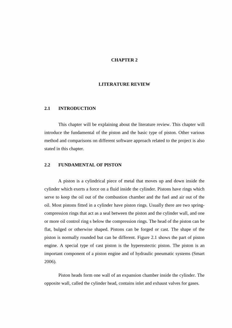
piston is normally rounded but can be different. Figure 2.1 shows the part of piston
engine. A special type of cast piston is the hypereutectic piston. The piston is an
important component of a piston engine and of hydraulic pneumatic systems (Smart
2006).
Piston heads form one wall of an expansion chamber inside the cylinder. The
opposite wall, called the cylinder head, contains inlet and exhaust valves for gases.
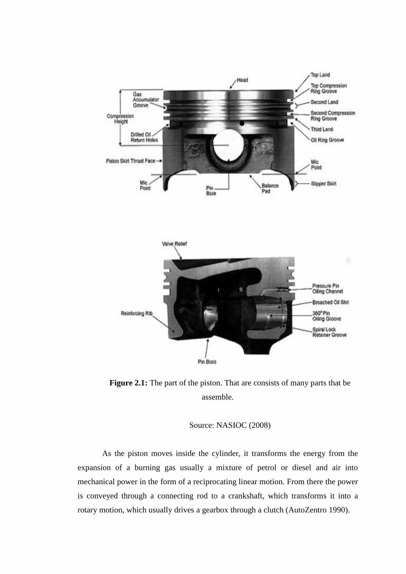
Figure 2.1: The part of the piston. That are consists of many parts that be
assemble.
Source: NASIOC (2008)
As the piston moves inside the cylinder, it transforms the energy from the
expansion of a burning gas usually a mixture of petrol or diesel and air into
mechanical power in the form of a reciprocating linear motion. From there the power
is conveyed through a connecting rod to a crankshaft, which transforms it into a
rotary motion, which usually drives a gearbox through a clutch (AutoZentro 1990).
2.3 TYPES OF PISTON
On this new modern century, many type of piston that have been design or
already in the market. Every type of piston has their capability and also has
limitation. Some of these types will now be considered (Stratman 2010).
2.3.1 Two-Stroke Piston
Figure 2.2 shows two stroke piston that be made by casting process. These
pistons are mainly used in gasoline and diesel engines for passenger cars under
heavy load conditions. They have cast-in steel strips but are not slotted. As a result,
they form a uniform body with extreme strength.
Figure 2.2: Two stroke piston.
2.3.2 Cast Solid Skirt Piston
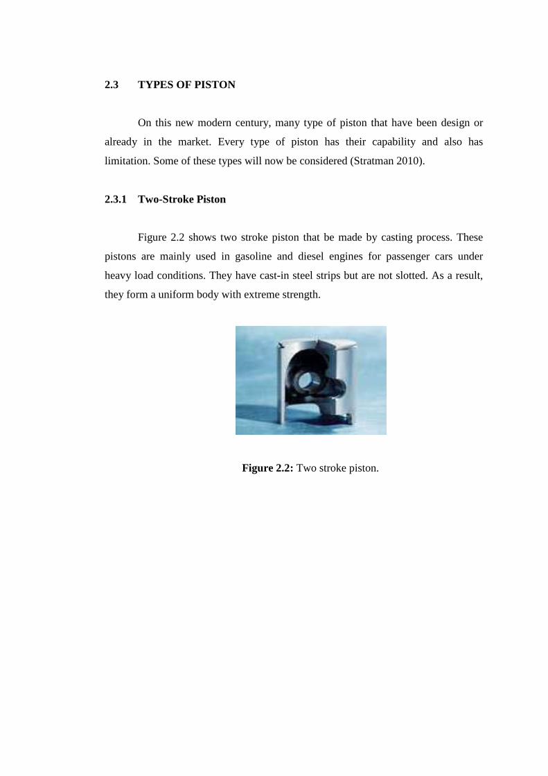
Cast solid skirt pistons have a long service life. Furthermore this piston more
useable that can be used in gasoline and diesel engines. Besides that, their range of
applications extends from model engines to large power units as shown in Figure 2.3.
Piston top, ring belt and skirt form a robust unit.
Figure 2.3: Piston cast solid skirt piston.
2.3.3 Forged Solid Skirt Piston
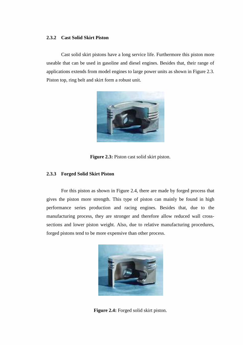
For this piston as shown in Figure 2.4, there are made by forged process that
gives the piston more strength. This type of piston can mainly be found in high
performance series production and racing engines. Besides that, due to the
manufacturing process, they are stronger and therefore allow reduced wall cross-
sections and lower piston weight. Also, due to relative manufacturing procedures,
forged pistons tend to be more expensive than other process.
Figure 2.4: Forged solid skirt piston.

2.3.4 Hydrothermik Piston
For this type of piston as shown in Figure 2.5, that gives very quiet running
pistons are used primarily in passenger cars. On the other hand, the pistons have cast-
in steel strips and are slotted at the transition from ring belt to skirt section.
Figure 2.5: Hydrothermik piston.
2.3.5 Hydrothermatik Piston
Mainly, these pistons are used in gasoline and diesel engines for passenger
cars under heavy load conditions as shown in Figure 2.6. They have cast-in steel
strips but are not slotted. Besides that, they form a uniform body with extreme
strength.
Figure 2.6: Hydrothermatik piston

2.3.6 Ring carrier pistons with pin boss bushes
This type of pistons is for diesel engines as shown in Figure 2.7. There have a
ring carrier made from special cast iron that is connected metallically and rigidly
with the piston material in order to make it more wear resistant, in particular in the
first groove. Furthermore, the pin boss bushes made from a special material, the
load-bearing capacity of the pin boss is increased.
Figure 2.7: Piston ring carrier pistons with pin boss bushes.
2.3.7 Ring carrier pistons with cooling channel
These types of piston that ring carrier pistons with cooling channel are used
in conditions with particularly high operating temperatures as shown in Figure 2.8.
Because of the high temperatures at the piston top and the ring belt, intensive cooling
is provided with oil circulating through the cooling channel.
Figure 2.8: Piston ring carrier pistons with cooling channel.
2.3.8 Ring carrier pistons with cooling channel and crown reinforcement
This is a piston ring carrier piston with cooling channel and crown
reinforcement as shown in the Figure 2.9. These pistons are used in diesel engines
under heavy load conditions. For additional protection and to avoid cavity edge or
crown fissures, these pistons have a special hard anodized layer (HA layer) on the
crown.
Figure 2.9: Ring carrier pistons with cooling channel and crown reinforcement
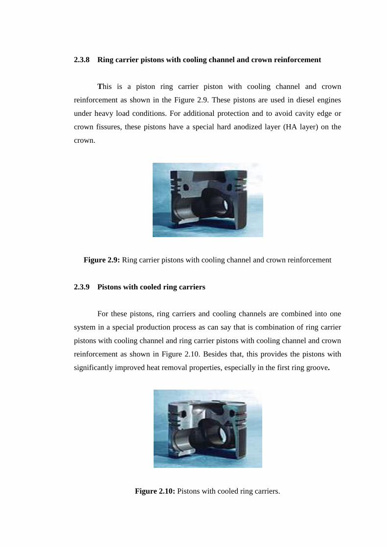
2.3.9 Pistons with cooled ring carriers
For these pistons, ring carriers and cooling channels are combined into one
system in a special production process as can say that is combination of ring carrier
pistons with cooling channel and ring carrier pistons with cooling channel and crown
reinforcement as shown in Figure 2.10. Besides that, this provides the pistons with
significantly improved heat removal properties, especially in the first ring groove.
Figure 2.10: Pistons with cooled ring carriers.