failure analysis of an alloy 718 barrel nut from an army ...the failures under investigation in this...
TRANSCRIPT

FAILURE ANALYSIS OF AN ALLOY 7 18
BARREL NUT FROM AN ARMY ATTACK HELICOPTER
V. K. Champagne, G. Wechsler, and M. S. Pepi
U.S. Army Research Laboratory, Materials Directorate 405 Arsenal St.
Watertown, MA 02 172
Dr. K. J. Bhansali
U.S Army Aviation and Troop Command 4300 Goodfellow Blvd. St. Louis, MO 63 120
Abstract
During a routine preflight inspection at Ft. Hood, an outboard barrel nut was found to be cracked on an Army helicopter. The part was fabricated from UNS NO771 8 material according to AMS 5662F “Alloy Bars, Forgings, and Rings, Corrosion and Heat Resistant”. Subsequent inspections at Ft. Hood and Ft. Rucker revealed an additional seven barrel nuts with large cracks. The components are used in many critical applications. The failures under investigation in this study were relegated to the vertical stabilizer of the aircraft. The failures were all attributed to hydrogen induced cracking. Galling between the unlubricated bolt and the nut threads provided the sustained hoop stress while galvanic corrosion of the carbon steel retaining clip in contact with the barrel nut generated hydrogen as a result of the corrosion process. Microstructural analysis of the material used to fabricate the nut revealed excessive banding consisting of a Widmanstatten phase and MC carbides which ran parallel to the fracture plane, The grains were almost completely surrounded by an undesirable acicular delta phase. No evidence of Laves phase was observed. Recommendations were made to utilize a corrosion inhibitive lubricant on the threads of the barrel nut and mating bolt to reduce galling and the consequential high stresses which result from metal to metal contact during torquing. A stress analysis of the part showed that the high strength level of the material could be reduced to increase fracture toughness and resistance to hydrogen cracking. The acicular delta phase should be avoided in accordance with AMS 5662F and the extrusion direction of the material should be parallel to the principal loading direction. Salt fog testing of the proposed barrel nut configuration revealed that the shoulder height base thickness should be increased. Future vendors should qualify their product by conducting a prescribed salt fog test incorporating the revised torque requirements. Finally, the material used to fabricate the retaining clip should be changed to prevent galvanic corrosion.
Superalloys 718, 625, 706 and Varmus Derivatives Edited by E.A. Loria
The.Minerals, Metals & Materials Society, 1997
813

Failure Scenario
According to the original engineering drawing, the only requirement placed on the barrel nut was its ability to withstand a specific load of 37,800 pounds (168000 N). Each manufacturer had considerable latitude in designing the conical threaded region (shoulder). Contractor A chose to design this region thinner than Contractor B, yet they both met the original drawing requirements. Based on salt fog tests and microscopic examination of the fracture surfaces, the following hypothesis was developed. UNS NO7718 alloy, being a nickel base alloy, is highly prone to galling. Absence of any lubricant during installation causes galling debris to wedge between the threads and in turn provides a source of constant hoop stress in the nut. The presence of a steel clip used for alignment purposes created a galvanic couple in which the nut became a cathode and the clip the anode. As a result, hydrogen was being charged into the nut during service. Consequently, after a period of time, a service induced hydrogen stress crack developed and grew until the hoop stress overloaded the remaining material. Since the failure was not in the thread, any sustained stress from the preload was ruled out as a potential cause. Since Contractor B nuts did not fail, the magnitude of the hoop stress was suspected to be important. However, the testing conducted to evaluate the effect of misalignment showed no significant detrimental effect.
Conclusion
The failure of the barrel nuts was attributable to hydrogen induced cracking. Galling between the unlubricated bolt and the nut thread provided the sustained hoop stress Galvanic coupling with the carbon steel retaining clip provided the source of hydrogen necessary for this mode of failure in the cold worked and aged microstructure.
Recommendations
1. A minimum height for the threaded conical section (shoulder) of the barrel nut should be specified and the thickness of the base increased to reflect the new proposed design.
2. The barrel nut and mating bolt should be wet installed utilizing MIL-T-83483, a molybdenum disulfide, anti-sieze thread compound to reduce galling and the consequential high tensile stresses which result from metal-to-metal contact during torquing (torque values would have to be re-adjusted from 1,850 to 975 in-lbs which is equivalent to 209 to 110 N.m).
3. The strength of the barrel nut should be reduced, if deemed feasible by stress analysis to increase the fracture toughness and resistance to hydrogen induced cracking of the material.
4. The acicular delta phase and excessive banding should be avoided in accordance with AMS- 5662F.
5. The carbon steel spring clip should be coated or fabricated from such material as stainless steel to avoid galvanic corrosion with the barrel nut and the resultant mitigation of atomic hydrogen.
6. The extrusion direction should be aligned parallel to the principal stress.
814

Background
During the early 1980’s several catastrophic failures of high strength H-l 1 fasteners were encountered by the aerospace industry. These failures were attributed to service induced hydrogen embrittlement. In response to this problem, the FAA issued an advisory against the use of such fasteners in critical applications. The Army Aviation and Troop Command (ATCOM) in turn issued an engineering order to replace all H-l 1 fasteners in critical applications on the Apache with those fabricated from UNS NO7718 in accordance with an engineering change proposal (ECP) submitted by the primary contractor. The ECP required that the UNS NO7718 material be heat treated to 220 ksi (1517 MPa) minimum ultimate tensile strength and cadmium plated incorporating a vacuum or an electrolytic deposition process. Approximately 8 to 10 months after the ECP was implemented, an outboard barrel nut was found cracked at Ft. Hood, during a routine preflight visual inspection.
This incident prompted further inspections at Ft. Hood and Ft. Rucker. An additional seven barrel nuts were found cracked. A total of three cracked barrel nuts were sent to the Army Research Laboratory (ARL) for examination. The first broken part was found during a pre- flight visual inspection at Ft. Hood. The two remaining barrel nuts were detected during visual inspection at Ft. Rucker. All the components were manufactured by the same company (designated within the context of this report as “Contractor A”) and were from the same lot number (03). There was also an alternative supplier to these parts (identified as “Contractor B”) but no failures were associated with this company.
In addition to the three failed components examined at ARL, 12 other barrel nut and bolt assemblies were subjected to salt fog testing while loaded. These parts represented three groups. Four parts were fabricated by Contractor A, and four others by Contractor B. The remaining parts represented a newly proposed design which were manufactured by Contractor B. These assemblies were exposed to a salt fog environment over a prescribed period of time or until failure and subsequently examined metallurgically. A series of barrel nuts fabricated by Contractor A were also mechanically loaded to failure over a conical mandrel and the resultant fracture surfaces compared to those of the failed components.
Visual Inspection/Light Optical Microscopy
Figure 1 shows the failed barrel nut assembly from Fort Hood, designated “H” in the as- received condition. The washer, spring clip, cradle and mating bolt have all been identified. A single crack (denoted by arrow) was observed on the barrel nut running perpendicular to the bolt threads. The fracture occurred parallel to the axial loading direction, The cradle was also cracked in two areas. The cadmium plated surfaces of the components displayed typical signs of wear but the shank of the bolt was almost entirely void of the plating from the region located above the barrel nut to the bolt head. The steel spring clip showed a significant amount of corrosion. No other unusual markings were observed.
The crack propagated through the entire thickness of the nut. The company insignia, part number (84209-820) and lot number (03) was still clearly visible. One of the legs of the cradle had actually bent outward from the component, most likely as a result of a post-fracture incident. The two other barrel nut failures from Fort Rucker identified as “Rl” and “R2”, displayed similar features and were also manufactured by Contractor A, lot number (03). The only significant difference was that both cracks in the cradle of the two Fort Rucker failures
815
were very easily discernible while one of the two cracks in the Fort Hood cradle was barely visible. Corrosion products were found on the surface of the cradle and the nut. The corrosion was reddish-brown in color and most likely originated from the steel spring clip. One of the two raised sections (legs) of the cradle had bent outward and the barrel nut was no longer square because the crack had widened a significant amount.
Examination of the threads on the barrel nuts revealed evidence of metal debris and wear. However, much of the cadmium plating on the threads was still intact. It is believed that some of this damage may have occurred during final fracture. As the crack propagated through the entire thickness of the barrel nut, the bolt is thought to have pulled out during that instant causing the bolt threads to shear. The two Fort Rucker bolt threads experienced shearing while the Fort Hood bolt did not. Some of the galling observed may have also occurred during installation since a lubricant was not used. Wear marks and exposed base material was also observed on the bolt threads that had been inserted into the barrel nut. Frictional forces between the mating threads of the bolt and barrel nut may have been sufficient enough to have caused some excessive wear and stress concentration areas.
Microstructure Analvsis
A transverse section (parallel to the fracture plane) was taken from each of the three failed barrel nuts. Figure 2 reveals the extrusion direction of barrel nut R2 which extends parallel to the direction of crack propagation. A transverse section of a Contractor B barrel nut was also examined for comparative purposes and the resultant flow pattern was perpendicular to that of the Contractor A counterpart and would be more desirable under the loading conditions encountered during service. Banding was also observed in both the Contractor A and Contractor B barrel nuts running in the same direction as their respective flow patterns. The Contractor A material displayed heavy banding which consisted primarily of MC carbides and delta phase in the form of a Widmanstatten structure. An acicular delta phase was also observed surrounding much of the grain boundaries, as shown in Figure 3. The Contractor B material contained only slight evidence of banding which was comprised primarily of MC carbides as shown in Figure 4. The Contractor A sample contained a large concentration of delta phase in the form of a Widmanstatten structure while the Contractor B material did not. The MC carbides which were aligned preferentially in the extrusion direction seemed to be found in clusters more often in the Contractor A material. The grain boundary delta phase was in the form of an acicular structure in the Contractor A material while the Contractor B material contained a more spherodized structure. Figure 5 is an optical micrograph representative of the Contractor A material at high magnification. The grains are almost completely surrounded by an acicular delta phase whereas the Contractor B microstructure contained a more spherodized grain boundary delta phase which surrounded a significantly smaller percentage of the grains, as depicted in Figure 6. The etchant used during this examination consisted of 100 ml of ethyl alcohol added to 100 ml of hydrochloric acid and 5 grams of cupric chloride.
The grain size was required to be 5 or finer (ASTM El1263). The grain size of the Contractor A and Contractor B material was measured utilizing this specification. A reference standard illustrating ranges of grain size (I-S) was superimposed on the photographs for ease in comparison. The Contractor A grain size was approximately 8 while the Contractor B material displayed a much finer grain size than that of the reference standard. However, both materials satisfied the specification requirements.
816

Carbides which form in UNS NO7718 are primarily MC type with a nominal NbC composition, although titanium and molybdenum can substitute for niobium in some circumstances. X-ray mapping was performed within the scanning electron microscope utilizing energy dispersive spectroscopy (EDS) of MC carbides found on both sets of samples. The results indicated a high concentration of Nb and MO. These carbides being very hard and brittle are usually considered undesirable because they reduce the ductility of the alloy. In addition, they tie up niobium necessary for the formation of the strengthening phases. There was no evidence of Laves phase found in any of the specimens examined. Chemical segregation can result in the formation of large, blocky intermetallic particles known as Laves phase which is also very
brittle and adversely affects the properties of the alloy. 1
A cross-section was taken through the crack origin and prepared metallographically for examination, Figure 7 represents the Fort Hood barrel nut failure. The fracture path appears to be quite intergranular at the origin, The specimen had been polished in relief to highlight the grains.
Chemical Analvsis
Material sectioned from a representative failed barrel nut and bolt (both from Rl) were subjected to chemical analysis. Atomic absorption and inductively coupled argon plasma emission spectrometry were used to determine the chemical composition of the alloys. The carbon and sulfur content was analyzed by the Leco Combustion Method. The compositional ranges of the material under investigation compared favorable with the published values.
A series of microhardness measurements were performed on cross sections of the three failed barrel nuts and a Contractor B barrel nut from inventory, for comparative purposes. Each nut was sectioned in half transversely and metallographically prepared. Knoop microhardness measurements were taken on the surface. The barrel nuts were required to exhibit a hardness of 42 HRC. The failed nut from Ft. Hood displayed an average hardness of 507 HK or approximately 47.8 HRC, while Rl was 515 HK or approximately 48.3 HRC. Specimen R2 was 525 HK or approximately 48.9 HRC and the Contractor B nut from inventory was 510 HK or approximately 48.0 HRC. All values obtained conformed to the governing specification, and were very close to one another.
Tensile specimens were sectioned from two failed barrel nuts (Rl and R2), as well as a Contractor B barrel nut from inventory. Substandard specimens were fabricated according to ASTM E8. The specimens were tested in a 20,000-pound (89000 N) (capacity Instron universal electromechanical test machine. A lO,OOO-pound (445000 N) load cell was utilized for the measurement of load. The pull rate was 0.05 inches/minute (1.3 mm/minute). Testing was conducted at room temperature at 50% relative humidity. The ultimate tensile strength was required to be 225,000 psi (155 1 MPa) minimum, and 245,000 (1689 MPa) maximum. The minimum per cent elongation was specified as 8 in 4D. The results of this testing are listed in Table 1.
817

Table I Tensile Test Results
Sample Diameter Area in (mm) in” (mm”)
Max. Load lbs. (N)
UTS psi @Pa)
%El
Rl 0.066(1.7) 0.0034(2.2) SOO(3560) 233,836(1612) 17.6 R2 0.078 (2.0) 0.0048 (3.1) 1,050(4670) 219,741 (1515) * Contractor B 0.066(1.7) 0.0034(2.2) 705(3140) 206,068(1421) 16.0
, * was not calculated
Fractoaraphic Examination
The three failed barrel nuts were sectioned to separate both fracture halves for examination. Optical and scanning electron microscopy was utilized to identify important features of the fracture surface relating to the failure mechanism. The Fort Hood barrel nut was determined to be representative of all three service failures and will be used within this discussion to describe the manner of crack propagation. Cracking occurred parallel to the axial loading direction or perpendicular to the threads. A discolored region was observed on the fracture surface near the crack origin. Energy dispersive spectroscopy (EDS) was utilized to characterize the chemistry of the surface within this area. The elements associated with the base material were detected as evidenced by Ni, Fe, Cr, Ti, Nb, MO and Al peaks. A large Cd peak and small 0 and Cl peaks were found and most likely represented corrosion product from one of the barrel nut assembly components that had been cadmium plated. Corrosion products of this cadmium plated part and the underlying base material could have seeped into the slowly propagating crack in the barrel nut causing a discolored zone. The reddish brown appearance of this stained region suggests that the corrosion products on this surface were rich in iron and may have originated from a steel component in contact with the barrel nut, such as the spring clip. Even though the EDS analysis supports this deduction an argument can be made that the Fe, Cd and 0 peaks may represent only the barrel nut material. However, the reddish brown appearance of the discolored region indicates corrosion of an iron rich material, The remaining elements are believed to be contaminants, although Si, S and Ca are acceptable within this alloy in very low concentrations. Figure 8 is an optical macrograph highlighting the fractographic features of the surface. The chevron markings and river pattern converge to an area identified as the crack initiation site as shown by the arrow.
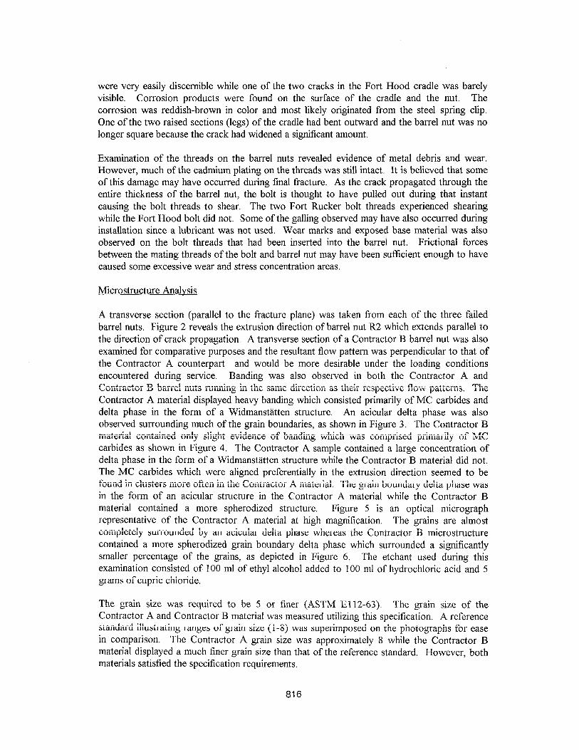
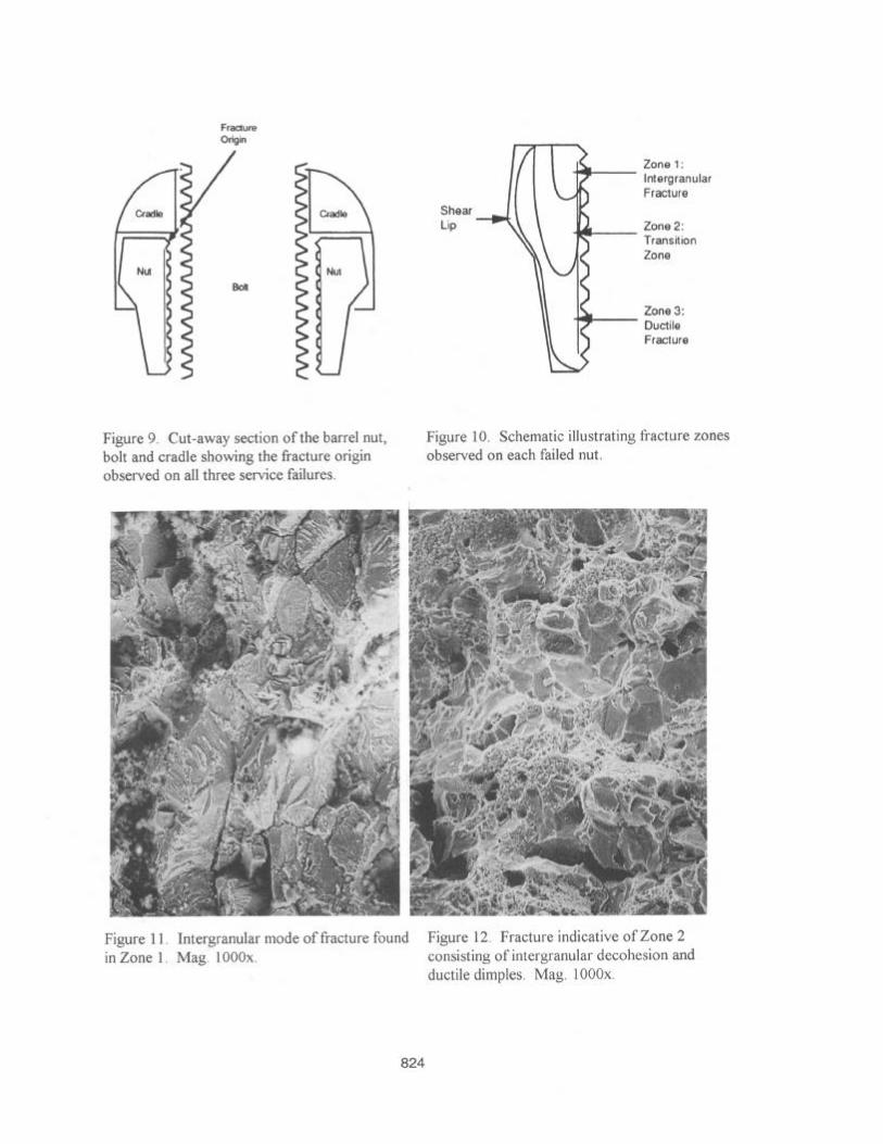
Figure 9 is a schematic illustrating a cut-away section of the barrel nut, bolt and cradle showing the location of the fracture origin observed on all three service failures. Cracking had initiated near the first thread of the barrel nut adjacent to the cradle. Figure 10 is a schematic illustrating the four distinct zones noted on the fracture surfaces. The fracture originated within the discolored region identified as Zone 1. This region was relatively free from smearing which can occur if the two fracture faces rub against one another in service, but contained surface contamination and debris. Cracking had occurred in a brittle manner which was discernible, even at relatively low magnification. Zone 1 was an area of slow crack growth showing little ductility and the morphology was intergranular as shown in Figure 11. Zone 2 was a region where fracture by intergranular decohesion transitioned to a more dimpled mode, as depicted in Figure 12. The fracture mode observed in Zone 3 consisted primarily of equiaxed dimples which is associated with ductility. Zone 4 consisted of shear lips adjacent to
818

the outside perimeter which displayed directional dimples. Crack propagation occurred at a faster rate within Zone 3 and final fracture took place within Zone 4.
Further EDS analysis was performed within the various zones of fracture. The spectrum obtained from Zones 3 and 4 revealed primarily those constituents associated with the base material. There was no significant Cd, Cl, or 0 peaks detected. A very large concentration of Cd, had been detected along with Cl and 0 near the crack origin site. The corrosion product observed on the surface of the barrel nut cradle was also analyzed by EDS. A significant concentration of Cl was detected. The Cd peak in this case primarily represents the plating on the surface of the cradle. The small Fe and 0 peak may represent corrosion product from the steel spring clip or the base material of the cradle. Fracture Zones 3 and 4 primarily contained those elements associated with the base material. No significant concentration of Cd or Cl was detected.
A series of Contractor A barrel nuts were subjected to mechanical testing. The barrel nuts were mechanically loaded to failure over a conical mandrel. Subsequent fractographic analysis of the failed barrel nuts revealed surfaces which were entirely dimpled. This type of fracture morphology is indicative of a ductile failure. Since the fracture surfaces of the failed barrel nuts displayed significant intergranular regions at the crack origin, it became evident that initial crack growth may have been environmentally induced.
Salt Spray Testing - Procedure
A series of three salt spray tests were conducted on Contractor A , B and newly designed barrel nut assemblies, in an effort to reproduce the failure mechanism and to compare the three barrel nut designs. The differences in design included the height of the conical section , the thickness of the base , and the hardness of the material .The assemblies were tested in an actual aluminum fuselage section. Bolts were inserted through a block of 6061-T6 aluminum, which represented the rear vertical stabilizer of the helicopter. Some of the blocks were machined with a 0.6 degree taper, while other blocks were flat and parallel. The taper was designed to induce a bending moment within the nut to replicate the effects of having a bolt inserted at an angle causing a stress concentration and galling when torqued. The bolts were threaded into the barrel nut assemblies and were then torqued and placed in a salt spray chamber. The bolts were incrementally torqued to higher stress levels at regular intervals following a schedule determined by ATCOM. The chamber maintained a salt fog with 5% NaCl by weight, at 95” F (35°C) and 100% relative humidity. During the torquing process, the assemblies were removed from the chamber for no longer than five minutes, Torquing was conducted utilizing
a digital torque wrench, having a capacity of 250 A-lbs (340 N,m).
Salt Spray - Results
Two Contractor A barrel nuts broke while being salt spray tested and the resultant fracture surfaces revealed similar features as the failed components (intergranular fracture at the crack origin and ductility in the area of final fracture). However, the region of intergranular fracture within the barrel nuts broken in the salt spray chamber was smaller than that of the three field failures. This was attributed to the higher torque levels prescribed during the laboratory salt fog test as opposed to the lower values specified in service. It is believed that higher stresses
819

would result in faster initial crack growth. The Contractor B and newly designed barrel nuts did not experience failure as did the Contractor A nuts tested under identical conditions. The use of tapered blocks to cause a slight mismatch and galling of the threads on the barrel nut and mating bolt did not contribute to premature failure of loaded barrel nuts during exposure to a salt spray atmosphere.
Discussion
The data obtained from examining and comparing the three Contractor A barrel nuts that failed in service, the two Contractor A barrel nuts that failed in the salt spray chamber test, the Contractor B barrel nuts from inventory and the proposed redesigned barrel nuts that did not fail the salt spray chamber test indicated that part geometry, microstructure, mating materials, lubrication and environment all contributed to premature failure. The smaller cross-sectional area at the conical threaded region (shoulder) of the Contractor A barrel nut contained less volume in which to distribute applied loads than the Contractor B and the newly designed barrel nuts. This resulted in higher stresses at this area during service. Another factor contributing to regions of high localized stress was the installation of the bolt into the barrel nut assembly. The wear and metal debris observed within the threaded section of the failed barrel nuts may have been attributable to improper seating of the bolt while torquing. Misalignment of the bolt caused by an uneven mating surface beneath the bolt head would result in surface galling during torquing. This condition would cause highly stressed areas in the barrel nut. Lubricity is also an important issue when uniform torque is required. The use of a corrosion inhibitive dry film lubricant would have helped to insure a uniform and consistent stress distribution within the barrel nut after torquing. High frictional forces as a result of metal-to-metal contact or parts that have a damaged cadmium plating could be avoided. Therefore, the risk of failure due to hydrogen induced cracking would be greater in the Contractor A barrel nuts.
The higher stresses in the Contractor A barrel nuts were compounded f%rther by a higher strength material and an undesirable microstructure. The Contractor A material contained an unacceptable acicular delta phase in the grain boundaries and in the form of a Widmanstatten structure throughout the grains. The ultimate tensile strength of the two Contractor A barrel nuts that failed in service measured higher than the ultimate tensile strength of a Contractor B barrel nut. The higher strength of the Contractor A barrel nuts increased its susceptibility to hydrogen absorption and decreased its toughness in comparison to the Contractor B barrel nut at the lower strength level.
The acicular delta phase observed metallographically within the microstructure of the Contractor A barrel nuts is considered a greater stress concentrator than the spheroidal delta phase found in the Contractor B barrel nuts. 2 The delta phase inhibits excessive grain growth in UNS NO7718 during the solutionizing and aging treatments, but it is a brittle phase and decreases the toughness of the material.3 Metallography also revealed MC carbides in both versions of the barrel nuts. These MC carbides are brittle (many were cracked when examined as a result of prior forming) and are stress concentrators. These carbides were preferentially orientated in the direction of extrusion and occurred in bands. The Contractor A material also contained a high concentration of Widmanstatten structure within these regions of banding. Banding in the Contractor A barrel nut occurred parallel to the plane of fracture, which is undesirable. Banding in the Contractor B barrel nut ran more favorably, in the direction of extrusion perpendicular to the Contractor A fracture plane. The MC carbides in the Contractor
820

A material seemed to be found more in clusters than in the Contractor B material. Together, the higher tensile strength, the acicular delta phase, and the banding decreased the toughness of the Contractor A barrel nuts.
Inspection of the Contractor A spring clips revealed that the cadmium plating and the steel clip were completely corroded. The cadmium plating of the spring clip was either scratched during installation or corroded during service eventually leaving the steel spring clip unprotected. Corrosion of the spring clip plating and the unprotected steel clip occurred when water was entrapped in the barrel nut receptacle machined in the aluminum fuselage. Oxidation occurred at the steel clip surface while monatomic hydrogen was produced at nearby cathodic sites as part of the electrochemical corrosion process. The high state of stress, grain boundary chemistry (acicular delta phase) in the Contractor A barrel nut is thought to have increased the susceptibility of this material to hydrogen charging. In addition, nickel is cathodic to steel in the presence of ionized water. The hydrogen would have preferentially migrated to sites of highest stress and disorder in the grain boundaries, Fractography of the Contractor A barrel nuts that failed in service showed that intergranular decohesion occurred at the crack initiation sites suggesting that cracking in these areas was environmentally assisted, Laboratory testing of Contractor A barrel nuts in a salt spray environment caused intergranular fracture at the crack origin. When testing was performed in the absence of an aggressive environment, as when the Contractor A barrel nut was forced over a conical mandrel during overload testing, fracture occurred in the same plane as the service and salt spray failures. However, the resultant morphology consisted entirely of ductile dimples. There was no initiation region of intergranular decohesion. Instead, the fracture initiated and propagated in a ductile dimpled mode. Therefore, the salt spray chamber and conical mandrel testing showed that fracture of the Contractor A barrel nuts in service would not have occurred in an intergranular mode if an aggressive environment was not present. Further evidence of the presence of an aggressive environment in the service failures of the Contractor A barrel nuts was found by EDS on the surface of the FT. Hood cradle and fracture surface of the barrel nut at the crack origin. Characteristic X-rays of chlorine, calcium and iron were collected that indicated chlorine and calcium ions were most likely present in water that caused the oxidation of iron (most likely the steel spring clip), both of which collected on the cradle surface as the water evaporated or drained out of the barrel nut receptacle in the aluminum fuselage.
References
1. P. J. DiConza, R. R. Biederman, and J. L. Burger, “Microstructural Characterization of Alloy 718,” Microstructural Science, 18 (1989) 91-92.
2. R. R. Biederman, private communication with professor, Worcester Polytechnic Institute, Department of Mechanical Engineering,
3. J. L. Burger, R. R. Biederman, and W. H. Coots, “The Effects of Starting Condition on the Aging Response of As-Forged Alloy 718,” Superalloy 718 - Metallurgy and Applications, p. 216, 1989.
821

Figure 1. Barrel nut assembly “H” in the as- received condition.
,
Figure 2. Extrusion direction of nut “R2”, parallel to crack. Mag. 20x.
Figure 3. Nut “H” microstructure showing banding and Widmanstatten delta phase in the extrusion direction. Mag. 200x.
Figure 4. Contractor “B” nut microstructure showing slight banding and MC carbides in the extrusion direction. Mag. 200x.
822

Figure 5. Contractor “A” microstructure displaying acicular delta phase at grain boundaries. Mag. 1000x.
Figure 6. Contractor “B” microstructure containing a spherodized grain boundary delta phase. Mag. 1500x.
._. us’13( 1~ -”
,)
)..1. ,,, /
Figure 7. Cross-section through crack origin of nut “H”. Note the intergranular fracture path. Mag. 400x. I
Figure 8. Fractograph of nut “H” showing crac origin and radial markings. Mag. 1 Ox.
323
Fracture Origm
cradle
~~
NUl
Boll
cradle
~~
NUI
Figure 9. Cut-away section of the barrel nut, bolt and cradle showing the fracture origin observed on all three service failures.
IFA- f%i;:,““lar Fracture
Shear Lip Zone 2:
Transition Zone
Zone 3: Ductile Fracture
Figure 10. Schematic illustrating fracture zones observed on each failed nut.
Figure Il. Intergranular mode of fracture found Figure 12. Fracture indicative of Zone 2 in Zone 1. Mag. 1000x. consisting of intergranular decohesion and
ductile dimples. Mag. 1000x.
824