fag special spherical roller bearings for vibratory machinery · pdf file2 tpi 197 schaeffler...
TRANSCRIPT

FAG Special Spherical Roller Bearingsfor Vibratory Machinery


Schaeffler Technologies TPI 197 1
Page
Contents
Features Operating conditions for bearings in vibratory machinery........... 2
Basic designs of FAG special spherical roller bearings ............... 2X-life spherical roller bearings 223..-E1-XL-T41A(D)............... 3X-life spherical roller bearings 223..-BE-XL-JPA-T41A ............. 3
Bearings with tapered bore ....................................................... 4
Bearings with coated bore......................................................... 4
Specification T41A (T41D)......................................................... 5Tolerances for bearing bore and outside diameter................. 5Radial internal clearance groups........................................... 6Reduction in radial internal clearance of bearingswith tapered bore................................................................. 6
Permissible radial acceleration ................................................. 10
Heat treatment.......................................................................... 10
Design andsafety guidelines
Dimensioning of bearings ......................................................... 11Calculation methods ............................................................ 11Basic rating life .................................................................... 11Expanded rating life ............................................................. 13Two bearing screen with circle throw..................................... 15Two bearing screen with straight line motion ........................ 18Eccentric screen ................................................................... 21Centrifugal force nomogram ................................................. 23Basic load rating nomogram ................................................. 25
Design of bearing arrangements................................................ 27Two bearing screen with circle throw..................................... 27Two bearing screen with straight line motion ........................ 31Four bearing screen.............................................................. 32
Lubrication of bearings ............................................................. 34Grease lubrication................................................................ 34Oil lubrication ...................................................................... 38Recommended lubricants ..................................................... 42
Monitoring of vibrating screens ................................................. 43
Dimension tables FAG special spherical roller bearings for vibratory machinery,with cylindrical bore,series 223..-E1-XL-T41A(D),series 223..-BE-XL-JPA-T41A...................................................... 46
Appendix Query for bearing calculation .................................................... 48

2 TPI 197 Schaeffler Technologies
FAG special spherical roller bearings for vibratory machinery
FeaturesOperating conditions
for bearingsin vibratory machinery
Vibratory screens used for grading, in other words the separationof solid materials according to grain size and other vibratory machinery such as road rollers and saw frames are among the machines subjected to the most severe stresses.The rolling bearings fitted in the exciter units of these machinesmust support not only high loads and high speeds but also acceler-ations and centrifugal forces. In many cases, these applications involve adverse environmental conditions such as contaminated environments and excessive moisture.The special spherical roller bearings developed by FAG are matched to the operating conditions in vibratory machinery and have proved highly successful in practical use.In particular, the cages of the rolling bearings are subjected to stresses arising from high radial accelerations. In unfavourable cases, these may be overlaid by axial accelerations as well.The rotating imbalance generates rotating shaft deflection and additional sliding motion within the bearings. This increasesthe friction and therefore the operating temperature of the bearings. FAG special spherical roller bearings can support dynamic angular misalignments of up to 0,15°. For larger misalignments, please consult Application Engineering at Schaeffler.
Basic designs of FAG specialspherical roller bearings
FAG special spherical roller bearings for vibratory machinery have main dimensions corresponding to dimension series 23 (DIN EN 616:1995-01, ISO 15). For the particular stresses occurring in vibratory machinery, we manufacture all the special spherical roller bearings described in this publication in accordance with specification T41A or T41D, see page 5. Very high load carrying capacity is achieved through optimum use of bearing cross-section as a result of further development of spherical roller bearings of series 223..-E1-XL in X-life quality.In the design for vibratory stresses, these bearings are supplied up to a bore diameter of 220 mm.
Schaeffler Technologies TPI 197 3
X-life spherical roller bearings223..-E1-XL-T41A(D)
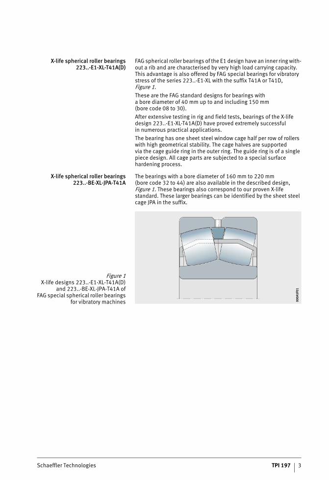
FAG spherical roller bearings of the E1 design have an inner ring with-out a rib and are characterised by very high load carrying capacity. This advantage is also offered by FAG special bearings for vibratory stress of the series 223..-E1-XL with the suffix T41A or T41D, Figure 1.These are the FAG standard designs for bearings witha bore diameter of 40 mm up to and including 150 mm(bore code 08 to 30).After extensive testing in rig and field tests, bearings of the X-life design 223..-E1-XL-T41A(D) have proved extremely successfulin numerous practical applications.The bearing has one sheet steel window cage half per row of rollers with high geometrical stability. The cage halves are supportedvia the cage guide ring in the outer ring. The guide ring is of a single piece design. All cage parts are subjected to a special surface hardening process.
X-life spherical roller bearings223..-BE-XL-JPA-T41A
The bearings with a bore diameter of 160 mm to 220 mm(bore code 32 to 44) are also available in the described design, Figure 1. These bearings also correspond to our proven X-life standard. These larger bearings can be identified by the sheet steel cage JPA in the suffix.
Figure 1X-life designs 223..-E1-XL-T41A(D)
and 223..-BE-XL-JPA-T41A ofFAG special spherical roller bearings
for vibratory machines 000A
5F01
000A
5F01

4 TPI 197 Schaeffler Technologies
FAG special spherical roller bearings for vibratory machinery
Bearings with tapered bore In special cases such as saw frames, bearings are also availablewith a tapered bore (taper 1:12). The ordering designations are respectively 223..-E1-XL-K-T41A and 223..-BE-XL-K-JPA-T41A.They are available with a bore diameter of or larger than 160 mm.
Bearings with coated bore In order to reduce or prevent fretting corrosion between the bearing bore and the shaft, we can for specific orders supply spherical roller bearings with a cylindrical bore coated with Durotect CK.This ensures that the possibility of displacement (non-locating bearing function) between the bearing bore and shaft in response to thermal influences is maintained over and beyond a long periodof operation.The bearings with a coated bore correspond in their dimensionsand tolerances to and are interchangeable with the FAG standard bearings for vibratory machinery.For bearings 22317-E1-XL-T41D to 22330-E1-XL-T41D, the cylindrical bore coated with Durotect CK is the standard. Further information is given in our publication PPD, FAG Special Spherical Roller Bearings with Durotect CK Coating in the Bore.For bearings outside this size range, a coated inner ring bore can be specified using the suffix J24BA in the ordering designation.Ordering example for a bearing with a Durotect CK coated bore:■ within the standard range:
22320-E1-XL-T41D■ outside the standard range:
22316-E1-XL-J24BA-T41A.

Schaeffler Technologies TPI 197 5
Specification T41A (T41D) FAG spherical roller bearings for vibratory machinery are manufac-tured in accordance with the specification T41A or T41D. This takes into consideration the particular requirements of the application. The specification defines, for example, the tolerances of bore and outside diameter, as well as the radial internal clearance of the bearings. The other tolerances are in accordance with tolerance class PN to DIN 620.
Tolerances for bearing bore andoutside diameter
The specification T41A(D) prescribes a restriction of the bore tolerance to approx. the upper half of the normal tolerance.For the outside diameter, only the centre half of the normal tolerance zone is permissible. In bearings with a tapered bore, the reduced tolerance range applies to the outside diameter only, see tables. Through these measures, the sliding fit required for the inner ringis reliably achieved with the shaft tolerances g6 or f6 and the interference fit required for the outer ring is reliably achievedwith the housing tolerance P6. For bearings with a coated bore,we recommend using the shaft tolerance f6. The inner ring does not have pure point load and the outer ring is subjected to circumfer-ential load. Geometrical and positional tolerances of bearing seating surfaces, see table, page 6.
Inner ring tolerances
Outer ring tolerances
Bore Bore deviation
d t�dmp
mm �m
over incl. max. incl.
30 50 0 –7
50 80 0 –9
80 120 0 –12
120 180 0 –15
180 250 0 –18
250 315 0 –21
Outside diameter Outside diameter deviation
D t�Dmp
mm �m
over incl. max. incl.
80 150 –5 –13
150 180 –5 –18
180 315 –10 –23
315 400 –13 –28
400 500 –13 –30
500 630 –15 –35
6 TPI 197 Schaeffler Technologies
FAG special spherical roller bearings for vibratory machinery
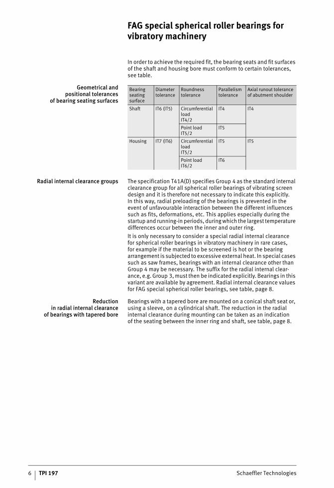
In order to achieve the required fit, the bearing seats and fit surfaces of the shaft and housing bore must conform to certain tolerances, see table.
Geometrical andpositional tolerances
of bearing seating surfaces
Radial internal clearance groups The specification T41A(D) specifies Group 4 as the standard internal clearance group for all spherical roller bearings of vibrating screen design and it is therefore not necessary to indicate this explicitly.In this way, radial preloading of the bearings is prevented in the event of unfavourable interaction between the different influences such as fits, deformations, etc. This applies especially during the startup and running-in periods, during which the largest temperature differences occur between the inner and outer ring.It is only necessary to consider a special radial internal clearancefor spherical roller bearings in vibratory machinery in rare cases,for example if the material to be screened is hot or the bearing arrangement is subjected to excessive external heat. In special cases such as saw frames, bearings with an internal clearance other than Group 4 may be necessary. The suffix for the radial internal clear-ance, e.g. Group 3, must then be indicated explicitly. Bearings in this variant are available by agreement. Radial internal clearance values for FAG special spherical roller bearings, see table, page 8.
Reductionin radial internal clearance
of bearings with tapered bore
Bearings with a tapered bore are mounted on a conical shaft seat or, using a sleeve, on a cylindrical shaft. The reduction in the radial internal clearance during mounting can be taken as an indicationof the seating between the inner ring and shaft, see table, page 8.
Bearing seating surface
Diameter tolerance
Roundness tolerance
Parallelism tolerance
Axial runout tolerance of abutment shoulder
Shaft IT6 (IT5) Circumferential loadIT4/2
IT4 IT4
Point loadIT5/2
IT5
Housing IT7 (IT6) Circumferential loadIT5/2
IT5 IT5
Point loadIT6/2
IT6

Schaeffler Technologies TPI 197 7

FAG special spherical roller bearings for vibratory machinery
8 TPI 197 Schaeffler Technologies
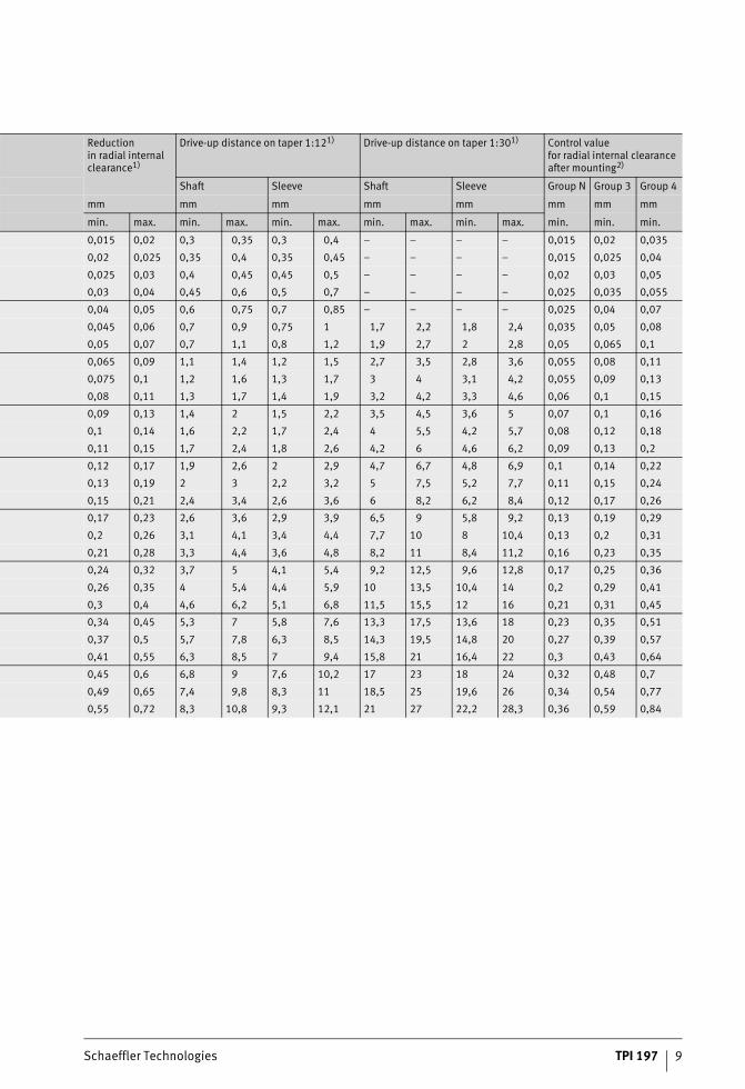
Reductionin radial internal clearance
of FAG spherical roller bearingswith tapered bore
1) Valid only for solid steel shafts and hollow shafts with a bore no largerthan half the shaft diameter.The following applies: Bearings with a radial internal clearance beforemounting in the upper half of the tolerance range are mounted usingthe larger value for the reduction in radial internal clearance or the axialdrive-up distance, while bearings in the lower half of the tolerancerange are mounted using the smaller value for the reduction in radialinternal clearance or the axial drive-up distance.
2) The actual value of the radial internal clearance must not be smaller thanthe control value. In the case of bearings with a small diameter, this maybe difficult to determine.
Nominalbearing bore diameter
Radial internal clearance before mountingInternal clearance group
d Group N Group 3 Group 4
mm mm mm mm
over incl. min. max. min. max. min. max.
24 30 0,03 0,04 0,04 0,055 0,055 0,075
30 40 0,035 0,05 0,05 0,065 0,065 0,085
40 50 0,045 0,06 0,06 0,08 0,08 0,1
50 65 0,055 0,075 0,075 0,095 0,095 0,12
65 80 0,07 0,095 0,095 0,12 0,12 0,15
80 100 0,08 0,11 0,11 0,14 0,14 0,18
100 120 0,1 0,135 0,135 0,17 0,17 0,22
120 140 0,12 0,16 0,16 0,2 0,2 0,26
140 160 0,13 0,18 0,18 0,23 0,23 0,3
160 180 0,14 0,2 0,2 0,26 0,26 0,34
180 200 0,16 0,22 0,22 0,29 0,29 0,37
200 225 0,18 0,25 0,25 0,32 0,32 0,41
225 250 0,2 0,27 0,27 0,35 0,35 0,45
250 280 0,22 0,3 0,3 0,39 0,39 0,49
280 315 0,24 0,33 0,33 0,43 0,43 0,54
315 355 0,27 0,36 0,36 0,47 0,47 0,59
355 400 0,3 0,4 0,4 0,52 0,52 0,65
400 450 0,33 0,44 0,44 0,57 0,57 0,72
450 500 0,37 0,49 0,49 0,63 0,63 0,79
500 560 0,41 0,54 0,54 0,68 0,68 0,87
560 630 0,46 0,6 0,6 0,76 0,76 0,98
630 710 0,51 0,67 0,67 0,85 0,85 1,09
710 800 0,57 0,75 0,75 0,96 0,96 1,22
800 900 0,64 0,84 0,84 1,07 1,07 1,37
900 1 000 0,71 0,93 0,93 1,19 1,19 1,52
1 000 1 120 0,78 1,02 1,02 1,3 1,3 1,65
1 120 1 250 0,86 1,12 1,12 1,42 1,42 1,8
1 250 1 400 0,94 1,22 1,22 1,55 1,55 1,96
Schaeffler Technologies TPI 197 9
Reductionin radial internal clearance1)
Drive-up distance on taper 1:121) Drive-up distance on taper 1:301) Control valuefor radial internal clearance after mounting2)
Shaft Sleeve Shaft Sleeve Group N Group 3 Group 4
mm mm mm mm mm mm mm mm
min. max. min. max. min. max. min. max. min. max. min. min. min.
0,015 0,02 0,3 0,35 0,3 0,4 – – – – 0,015 0,02 0,035
0,02 0,025 0,35 0,4 0,35 0,45 – – – – 0,015 0,025 0,04
0,025 0,03 0,4 0,45 0,45 0,5 – – – – 0,02 0,03 0,05
0,03 0,04 0,45 0,6 0,5 0,7 – – – – 0,025 0,035 0,055
0,04 0,05 0,6 0,75 0,7 0,85 – – – – 0,025 0,04 0,07
0,045 0,06 0,7 0,9 0,75 1 1,7 2,2 1,8 2,4 0,035 0,05 0,08
0,05 0,07 0,7 1,1 0,8 1,2 1,9 2,7 2 2,8 0,05 0,065 0,1
0,065 0,09 1,1 1,4 1,2 1,5 2,7 3,5 2,8 3,6 0,055 0,08 0,11
0,075 0,1 1,2 1,6 1,3 1,7 3 4 3,1 4,2 0,055 0,09 0,13
0,08 0,11 1,3 1,7 1,4 1,9 3,2 4,2 3,3 4,6 0,06 0,1 0,15
0,09 0,13 1,4 2 1,5 2,2 3,5 4,5 3,6 5 0,07 0,1 0,16
0,1 0,14 1,6 2,2 1,7 2,4 4 5,5 4,2 5,7 0,08 0,12 0,18
0,11 0,15 1,7 2,4 1,8 2,6 4,2 6 4,6 6,2 0,09 0,13 0,2
0,12 0,17 1,9 2,6 2 2,9 4,7 6,7 4,8 6,9 0,1 0,14 0,22
0,13 0,19 2 3 2,2 3,2 5 7,5 5,2 7,7 0,11 0,15 0,24
0,15 0,21 2,4 3,4 2,6 3,6 6 8,2 6,2 8,4 0,12 0,17 0,26
0,17 0,23 2,6 3,6 2,9 3,9 6,5 9 5,8 9,2 0,13 0,19 0,29
0,2 0,26 3,1 4,1 3,4 4,4 7,7 10 8 10,4 0,13 0,2 0,31
0,21 0,28 3,3 4,4 3,6 4,8 8,2 11 8,4 11,2 0,16 0,23 0,35
0,24 0,32 3,7 5 4,1 5,4 9,2 12,5 9,6 12,8 0,17 0,25 0,36
0,26 0,35 4 5,4 4,4 5,9 10 13,5 10,4 14 0,2 0,29 0,41
0,3 0,4 4,6 6,2 5,1 6,8 11,5 15,5 12 16 0,21 0,31 0,45
0,34 0,45 5,3 7 5,8 7,6 13,3 17,5 13,6 18 0,23 0,35 0,51
0,37 0,5 5,7 7,8 6,3 8,5 14,3 19,5 14,8 20 0,27 0,39 0,57
0,41 0,55 6,3 8,5 7 9,4 15,8 21 16,4 22 0,3 0,43 0,64
0,45 0,6 6,8 9 7,6 10,2 17 23 18 24 0,32 0,48 0,7
0,49 0,65 7,4 9,8 8,3 11 18,5 25 19,6 26 0,34 0,54 0,77
0,55 0,72 8,3 10,8 9,3 12,1 21 27 22,2 28,3 0,36 0,59 0,84

10 TPI 197 Schaeffler Technologies
FAG special spherical roller bearings for vibratory machinery
Permissible radial acceleration Since the centrifugal forces are supported against the outer ring, high acceleration forces are possible in FAG special spherical roller bearings for vibratory machinery, Figure 2.Permissible radial acceleration values of FAG special spherical roller bearings for the dimension series 223 (n = operating speed, dM = mean bearing diameter):■ n · dM = 350 000 min–1 · mm
Maximum possible values with optimum mounting conditions and oil lubrication, e.g. planetary gearbox
■ n · dM = 140 000 min–1 · mmNormal operating conditions for saw frameswith grease lubrication
■ n · dM = 230 000 min–1 · mm to 300 000 min–1 · mmNormal operating conditions for vibrating screens with grease or oil lubrication.
Heat treatment All FAG spherical roller bearings of series 223..-E1-XL-T41A(D) and 223..-BE-XL-JPA-T41A for vibratory stresses are heat treated such that they are dimensionally stable up to an operating temperatureof +200 °C.
g = gravitational accelerationd = bearing diameter
� n · dM = 350 000 min–1 · mm� n · dM = 140 000 min–1 · mm� n · dM = 230 000 min–1 · mm
to 300 000 min–1 · mm
Figure 2Permissible radial acceleration
000A
5F0A
000A
5F0A

Schaeffler Technologies TPI 197 11
Design andsafety guidelines
Dimensioning of bearings Vibrating screen bearings are normally designed for a basic rating life of between 10 000 hours and 20 000 hours.When determining the equivalent dynamic load P of sphericalroller bearings for vibratory stresses, the influences that cannot be precisely defined are taken into consideration by means of a safety factor fz of 1,2 times the radial bearing load Fr. Based on practical experience, this gives sufficiently long running times. More precise calculations can be achieved by determining the expanded adjusted rating life Lhnm to ISO 281. The fatigue limit load Cur required in this case is stated in the dimension tables.
Calculation methods Methods for calculating the rating life include the following:■ basic rating life L10 and L10h to ISO 281■ expanded rating life Lnm and Lnmh to ISO 281.
Basic rating life The basic rating life L10 and L10h is determined as follows:
L10 106 revolutionsThe basic rating life in millions of revolutions that is reached or exceededby 90% of a sufficiently large group of apparently identical bearings beforethe first evidence of material fatigue developsC NBasic dynamic load ratingP NEquivalent dynamic bearing load for radial and axial bearingsp –Life exponent;for roller bearings: p = 10/3for ball bearings: p = 3L10h hThe basic rating life in operating hours according to the definition for L10n min–1
Operating speed.

12 TPI 197 Schaeffler Technologies
FAG special spherical roller bearings for vibratory machinery
Equivalent dynamic bearing load The equivalent dynamic load P is a calculated value.This value is constant in magnitude and direction; it is a radial load for radial bearings and an axial load for axial bearings.A load corresponding to P will give the same rating life asthe combined load occurring in practice.
P NEquivalent dynamic bearing loadX –Radial factor given in the dimension tables or product descriptionFr NRadial dynamic bearing loadY –Axial factor given in the dimension tables or product descriptionFa NAxial dynamic bearing load.
This calculation cannot be applied to radial needle roller bearings, axial needle roller bearings and axial cylindrical roller bearings. Combined loads are not permissible with these bearings.For radial needle roller bearings under purely radial load, P = Fr,for axial needle roller bearings and axial cylindrical roller bearings under purely axial load, P = Fa.
Influencing factors Influencing factors can include, Figure 3:■ bearing alignment■ bearing loads■ operating clearance■ tilting and moment load■ lubrication and contamination.
F = loadM = torque
� = radial deflection� = tilting angle
Figure 3Calculation model 00
019C
0D00
019C
0D

Schaeffler Technologies TPI 197 13
Expanded rating life The calculation of the expanded rating life Lnm and Lnmh was stand-ardised for the first time in DIN ISO 281 Appendix 1. Since 2007,it has been standardised in the worldwide standard ISO 281.Computer-aided calculation to DIN ISO 281 Appendix 4 has been specified since 2008 in ISO/TS 16281 and standardised in DIN 26281.The rating life Lnm and Lnmh is calculated as follows:
Lnm 106 revolutionsExpanded adjusted rating life to ISO 281a1 –Life adjustment factor for a requisite reliability other than 90% Requisite reliability 90% (L10m) a1 = 1Requisite reliability 95% (L5m) a1 = 0,64Requisite reliability 99% (L1m) a1 = 0,25aISO –Life adjustment factor for operating conditionsL10 106 revolutionsbasic rating lifeLnmh hExpanded rating life in operating hoursL10h hBasic rating life in operating hours according to the definition for L10.
The values for the life adjustment factor a1 were redefinedin ISO 281:2007 and differ from the previous data.

14 TPI 197 Schaeffler Technologies
FAG special spherical roller bearings for vibratory machinery
Life adjustment factor aISO The standardised method for calculating the life adjustment factor aISO essentially takes account of the following factors:■ the load on the bearing■ the lubrication conditions (viscosity and type of lubricant, speed,
bearing size, additives)■ the fatigue limit of the material■ the type of bearing■ the residual stress in the material■ the ambient conditions■ contamination of the lubricant.
The life adjustment factor aISO is calculated as follows:
aISO –Life adjustment factor for operating conditionseC –Life adjustment factor for contaminationCu NFatigue limit load� –Viscosity ratio;for � � 4 a value of � = 4 should be anticipatedfor � � 0,1 this calculation method cannot be usedP NEquivalent dynamic bearing load.

Schaeffler Technologies TPI 197 15
Two bearing screen with circle throw The schematic of an imbalance-type two bearing screen is shownin Figure 4.
The radial bearing load imposed by the centrifugal force of the screen box is derived from the screen box weight, the vibration radius and the speed in accordance with the following equation:
Fr kNRadial bearing loadm kgScreen box massr mVibration radius 1/sAngular velocityG kNScreen box weightn min–1
Speedz –Number of bearingsg m/s2
Gravitational acceleration; g = 9,81 m/s2.
G = screen boxG1 = exciter weight
R = distance between centre of gravityof exciter and bearing axis
r = vibration radius of screen box
Figure 4Schematic of two bearing screen
with circle throw 000A
5F3A
000A
5F3A

16 TPI 197 Schaeffler Technologies
FAG special spherical roller bearings for vibratory machinery
The vibration radius r in two bearing screens can be determinedfrom the ratio of the screen box weight to the exciter weight.Since two bearing screens generally operate between the critical range approaching the static amplitude, it can be assumed thatthe common centroidal axis of the two masses of the screen box and exciter is maintained during rotation, Figure 5.
Based on this precondition:
The vibration radius r is thus:
G kNScreen box weightr mVibration radius of screen boxG1 kNExciter weightR mDistance between centre of gravity of exciter and bearing axisG1 ·R kN/mImbalance moment of exciterG + G1 kNTotal weight supported by springs.
If the vibration radius r is incorporated in the equation for calculation of the radial bearing load Fr, transformation gives:
G = screen box weightG1 = exciter weight
R = distance between centre of gravityof exciter and bearing axis
r = vibration radius of screen box
Figure 5The vibration radius is determined
by the ratio of the screen box weightto the exciter weight 00
0A5F
4700
0A5F
47

Schaeffler Technologies TPI 197 17
Example Data for calculation:
From the data, the radial bearing load is calculated as follows:
The equivalent dynamic bearing load required in order to determine the requisite basic dynamic load rating of the bearing is then:
■ Screen box weight G = 35 kN■ Vibration radius r = 0,003 m■ Speed n = 1200 min–1
■ Number of bearings z = 2.

18 TPI 197 Schaeffler Technologies
FAG special spherical roller bearings for vibratory machinery
Two bearing screenwith straight line motion
In principle, the exciter in a two bearing screen with straight line motion comprises two contra-rotating synchronous circular throw systems, Figure 6.
The forces are determined by resolving the rotating centrifugalforce vectors of the imbalance shafts into two components,in the direction of the line connecting the two shafts andthe direction perpendicular to this line. It can be seen that the components lying in the direction of the connecting line canceleach other out, whereas the perpendicular components add up, generating a harmonic pulsating inertia force that induces straight line vibration of the screen box. Since the so-called static amplitude is induced in the direction of vibration due to the supercritical operation and the common centroidal axis of the screen box andthe imbalance masses does not vary during vibration, the bearing loads are as follows.
G = screen box weightG1 = exciter weight
R = distance between centre of gravity ofexciter and bearing axis
r = vibration radius of screen box
Figure 6Schematic of two bearing screen
with straight line motion 000A
5F5F
000A
5F5F

Schaeffler Technologies TPI 197 19
In the direction of vibration, the radial bearing load is as follows:
Perpendicular to the direction of vibration, there is a significantly higher radial bearing load:
In contrast to a circle throw screen, in which the bearing load is constant, the bearing load in a straight line screen alternates twice during one revolution of the exciter shafts between Fr max and Fr min. If the equation for calculating the minimum radial bearing load Fr min with the equation for calculating the radial bearing load Fr,it can be seen that the minimum radial bearing load of a screenwith straight line motion is exactly the same as the radial bearing load of a comparable circle throw screen.For a straight line screen with a load varying according to a sinus-oidal function, the radial bearing load Fr can be determined using the following equation:
Whereas the bearing load in a circle throw screen can be determined simply from data for the screen box screen box weight G,the vibration radius r and the speed n, these data only allow calculation of the minimum bearing load in a straight line screen.For more precise calculation, it is also necessary to know eitherthe exciter weight G1 or the distance R between the centres of gravity of the exciters and their bearing axes.The missing value can be determined using the following equation:
20 TPI 197 Schaeffler Technologies
FAG special spherical roller bearings for vibratory machinery
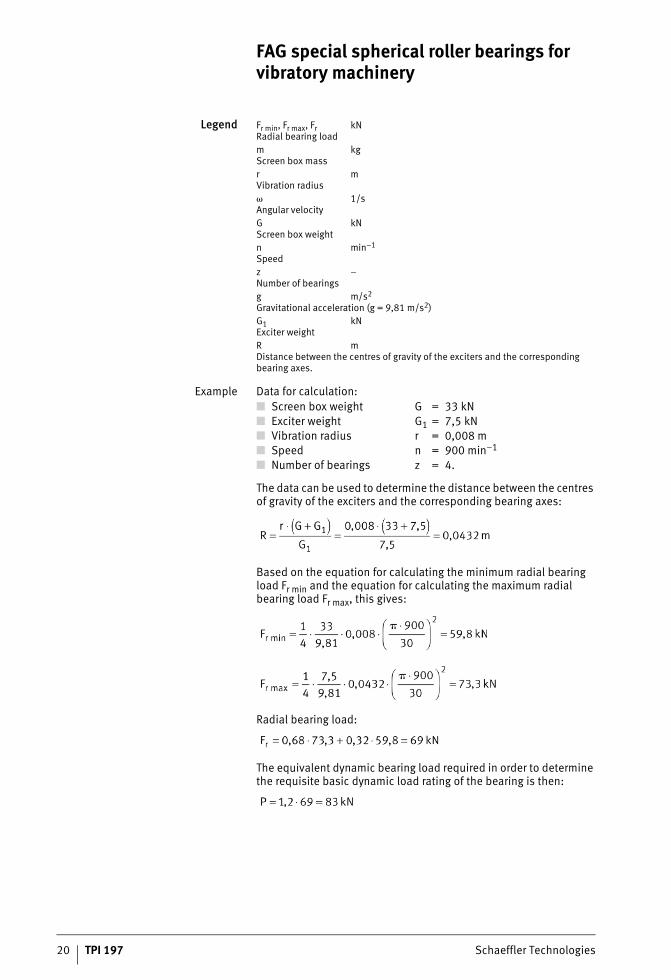
Legend Fr min, Fr max, Fr kNRadial bearing loadm kgScreen box massr mVibration radius 1/sAngular velocityG kNScreen box weightn min–1
Speedz –Number of bearingsg m/s2
Gravitational acceleration (g = 9,81 m/s2)G1 kNExciter weightR mDistance between the centres of gravity of the exciters and the corresponding bearing axes.
Example Data for calculation:
The data can be used to determine the distance between the centres of gravity of the exciters and the corresponding bearing axes:
Based on the equation for calculating the minimum radial bearing load Fr min and the equation for calculating the maximum radial bearing load Fr max, this gives:
Radial bearing load:
The equivalent dynamic bearing load required in order to determine the requisite basic dynamic load rating of the bearing is then:
■ Screen box weight G = 33 kN■ Exciter weight G1 = 7,5 kN■ Vibration radius r = 0,008 m■ Speed n = 900 min–1
■ Number of bearings z = 4.
Schaeffler Technologies TPI 197 21
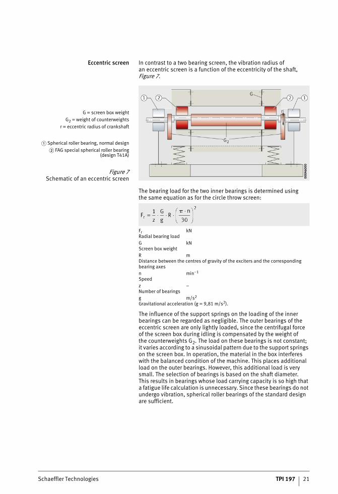
Eccentric screen In contrast to a two bearing screen, the vibration radius ofan eccentric screen is a function of the eccentricity of the shaft, Figure 7.
The bearing load for the two inner bearings is determined usingthe same equation as for the circle throw screen:
Fr kNRadial bearing loadG kNScreen box weightR mDistance between the centres of gravity of the exciters and the corresponding bearing axesn min–1
Speedz –Number of bearingsg m/s2
Gravitational acceleration (g = 9,81 m/s2).
The influence of the support springs on the loading of the inner bearings can be regarded as negligible. The outer bearings of the eccentric screen are only lightly loaded, since the centrifugal forceof the screen box during idling is compensated by the weight ofthe counterweights G2. The load on these bearings is not constant;it varies according to a sinusoidal pattern due to the support springs on the screen box. In operation, the material in the box interferes with the balanced condition of the machine. This places additional load on the outer bearings. However, this additional load is very small. The selection of bearings is based on the shaft diameter.This results in bearings whose load carrying capacity is so high that a fatigue life calculation is unnecessary. Since these bearings do not undergo vibration, spherical roller bearings of the standard design are sufficient.
G = screen box weightG2 = weight of counterweights
r = eccentric radius of crankshaft
� Spherical roller bearing, normal design� FAG special spherical roller bearing
(design T41A)
Figure 7Schematic of an eccentric screen 00
0A60
0000
0A60
00

22 TPI 197 Schaeffler Technologies
FAG special spherical roller bearings for vibratory machinery
Example Data for calculation:
From the data, the radial bearing load of the inner bearings is calculated as follows:
The equivalent dynamic bearing load required in order to determine the requisite basic dynamic load rating of the bearing is then:
■ Screen box weight G = 60 kN■ Eccentric radius r = 0,005 m■ Speed n = 850 min–1
■ Number of bearings z = 2.

Schaeffler Technologies TPI 197 23
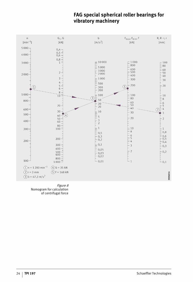
Nomogram for calculationof centrifugal force
Calculation of the centrifugal force of the imbalance masses orthe centrifugal force of the screen box mass can be carried outin graphical form with the aid of a diagram, the so-called centrifugal force nomogram, Figure 8, page 24.The centrifugal forces are determined according to the following equation:
Fmax, Fmin, F kNCentrifugal forcesG1 kNImbalance mass weightR mDistance between centre of gravity of exciter and bearing axisn min–1
Speedg m/s2
Gravitational acceleration (g = 9,81 m/s2)r mVibration radiusb m/s2
Acceleration, Figure 8, page 24.
24 TPI 197 Schaeffler Technologies
FAG special spherical roller bearings for vibratory machinery
Figure 8Nomogram for calculation
of centrifugal force
000A
6016
000A
6016

Schaeffler Technologies TPI 197 25
Nomogram for calculationof basic load ratings
Calculation of the basic dynamic load rating C can also be carried out in graphical form with the aid of a diagram, the so-called basic load rating nomogram, Figure 9, page 26.The following are required in order to calculate the basic dynamic load rating C:■ speed n in min–1
■ basic rating life Lh in h■ equivalent dynamic load P in kN.
In two bearing screens with circle throw and inner bearingswith eccentric screens, the following applies:
In two bearing screens with straight line motion,the following applies:
where:■ 1,2 = safety factor■ z = number of bearings■ F = centrifugal force.

26 TPI 197 Schaeffler Technologies
FAG special spherical roller bearings for vibratory machinery
Figure 9Nomogram for calculation
of basic load ratings
000A
6021
000A
6021

Schaeffler Technologies TPI 197 27
Designof bearing arrangements
The design of bearing positions is illustrated below by meansof several examples.
Two bearing screen with circle throw This section describes the bearing arrangements of two bearing screens with grease lubrication, oil sump lubrication and recirculating oil lubrication.
Grease lubrication The schematic design of the bearing arrangement in a two bearing screen with circle throw and grease lubrication is shown in Figure 10. The imbalance shaft is supported in two FAG special spherical roller bearings 223..-E1-XL-T41A. The bearing on the drive side is fittedas a locating bearing while the opposing bearing is a non-locating bearing.
� Locating bearing� Non-locating bearing� Flange of guard tube
� Grease baffle� Grease collector pocket
Figure 10Two bearing screen with circle throw
(grease lubrication) 000A
6048
000A
6048

28 TPI 197 Schaeffler Technologies
FAG special spherical roller bearings for vibratory machinery
After inspection of the adjacent parts, the bearing is then mounted in the housing bore. Smaller bearings can be pressed in while cold. For larger bearings, the housing is heated uniformly to the point where the interference between the bearing outer ring and housing bore is eliminated. As the housing cools down, the interference fitis achieved. The bearing and housing are then slid onto the shaft.For dismounting, it is easier to press the bearing out of the housing if the guard tube flange is replaced by a screw mounted ring, Figure 10, �, page 27, with several extraction screws on its circumference.A favourable option is to feed the grease as shown here via the circumferential groove and the lubrication holes in the bearing outer ring. In this way, the fresh grease is fed directly to the rolling and sliding surfaces of the rolling bearing, ensuring uniform lubrication of both rows of rollers. The fresh grease displaces the old, possibly contaminated grease from the interior of the bearing. On the inner side of the bearing arrangement, the old grease escapes via the gap in the grease baffle and collects in the guard tube. On the outer side, it collects at the grease collector pocket, from which it is periodically removed. The bearing is sealed against external influences bya labyrinth that can be relubricated and whose sealing action can be further increased by a V ring on the innermost labyrinth passage.

Schaeffler Technologies TPI 197 29
Oil sump lubrication The schematic design of the bearing arrangement of a two bearing screen with circle throw and oil sump lubrication is shown in Figure 11. Sealing against the ingress of contaminant from outside is provided by a labyrinth filled with grease that can be relubricated. Egress of oil is prevented by a splash ring with an oil collector groove. On the bearing side, the sealing area is shielded by a flinger ring.In order to prevent the grease in the labyrinth entering the oil cavities, a V ring is fitted between the labyrinth and splash ring.The connecting hole in the lower section of the housing equalises the oil sump level between the two sides of the bearing. The oil level should be such that the lowest roller in the bearing is immersed to approximately half its diameter in oil when the bearing is stationary. At this level, there is an overflow hole that is closed off after the housing is filled. The oil outlet screw contains a small permanent magnet that draws wear particles out of the oil. In general, the shaft guard tube is used as an additional oil container.
� Locating bearing� Non-locating bearing
� Vent screw� Flinger ring
� Oil overflow hole� Connecting hole� Oil outlet screw
Figure 11Two bearing screen with circle throw
(oil sump lubrication) 000A
606F
000A
606F

30 TPI 197 Schaeffler Technologies
FAG special spherical roller bearings for vibratory machinery
Recirculating oil lubrication The design of the bearing arrangement with recirculating oil lubrication shown in Figure 12 is similar to that of the bearing arrangement with oil sump lubrication, see page 29.The connecting hole in the lower section of the housing equalises the oil level between the two sides of the bearing.The sealing arrangement is taken from the oil sump lubrication.The oil outlet hole is located at such a level that, even if the oil feed is interrupted, there is still an emergency oil reserve available.The oil is fed via the lubrication groove and lubrication holes in the bearing outer ring. Oil filtration is absolutely essential, see page 41.
� Locating bearing� Non-locating bearing
Figure 12Two bearing screen with circle throw
(recirculating oil lubrication) 000A
6229
000A
6229

Schaeffler Technologies TPI 197 31
Two bearing screenwith straight line motion
This section describes the bearing arrangement of a two bearing screen with oil injection lubrication.
Oil injection lubrication The bearing arrangement of an exciter for a two bearing screen with straight line motion is shown in Figure 13. The two contra-rotating, synchronously geared imbalance shafts are fitted with FAG special spherical roller bearings 223..-E1-XL-T41A. The bearings on the gear side are fitted as locating bearings in order to prevent disruptionto the gear cycling behaviour if length variations occur (temperature differences).The bearings are lubricated by the oil thrown off by the gears anda flinger shield. The baffle plates on the lower halves of the housing end faces ensure that the oil level reaches approximately the centre of the lowest roller in the bearings.The passage for the drive shaft is equipped with a splash ring seal and, in order to prevent ingress of contamination, with a labyrinth.A V ring can also be fitted between the labyrinth and splash ring.The oil level is just high enough that the lower gear and flinger shield are immersed in the oil sump. The oil level is monitored by lateral oil level indicators.
� Locating bearing� Non-locating bearing
� Baffle plates� Oil level indicator
Figure 13Two bearing screen
with straight line motion(oil splash lubrication) 00
0A63
8100
0A63
81

32 TPI 197 Schaeffler Technologies
FAG special spherical roller bearings for vibratory machinery
Four bearing screen This section describes the bearing arrangement of a four bearing screen with grease lubrication.
Grease lubrication The eccentric shaft of a four bearing screen is shown in Figure 14, page 33. Since the stresses acting on the inner bearings are com-parable with those acting on the bearings of a two bearing screen, these positions are fitted with FAG special spherical roller bearings of series 223..-E1-XL-T41A.Although the interaction of the rotating screen box centrifugal force and the directionally constant spring forces does not give a pure point load on the inner ring, the fits selected are generally the same as for the two bearing screen.The outer rings have a P6 fit in the housing, while the inner rings have a f6 or g6 fit on the shaft. One of the two inner bearings isfitted as a locating bearing, while the other is a non-locating bearing with an inner ring that can be displaced along the shaft.In all other respects, the design of the inner bearing arrangement shown is identical to the bearing arrangement for a two bearing screen with grease lubrication.Conditions are different in the outer bearings. In order to ensure that, if possible, imbalance forces are not transmitted to the foundations and the bearing load remains low, the imbalance moment ofthe screen box in the eccentric screen is compensated by meansof counterweights. During idling, the outer bearings are only sub-jected to the forces exerted by the support springs. The support springs are preloaded to such an extent that the outer bearings are subjected to a sinusoidally pulsating but directionally constant radial load. Although the precisely balanced condition is disrupted during operation by the material in the box – the spring forcesare overlaid by an uncompensated rotating centrifugal force –and the load direction may therefore vary within a certain angle,the bearing fits are determined on the assumption that the outer ring is subjected to point load.A loose fit must therefore be selected for the outer rings in the housing bore. The inner rings are normally located on the shaft –as shown – using withdrawal sleeves. The bearing on the drive side is fitted as a locating bearing while the opposing bearing is a non-locating bearing with an outer ring capable of axial displacement.

Schaeffler Technologies TPI 197 33
Normal machining tolerances that have proved effective for the outer bearing seats are:■ shaft: H8/h9
(shaft tolerance for withdrawal sleeve location)■ housing: H7.Since the outer bearings do not undergo translation movement and are only subject to light loads, normal spherical roller bearingswith a tapered bore and normal internal clearance can be selected.
� Locating bearing� Non-locating bearing
� Counterweight
Figure 14Four bearing screen(grease lubrication) 00
0A63
B000
0A63
B0

34 TPI 197 Schaeffler Technologies
FAG special spherical roller bearings for vibratory machinery
Lubrication of bearings Spherical roller bearings in vibratory machinery are subjected to very high operating loads and adverse environmental conditions.The lubricant type, lubrication method and lubricant supply must be carefully selected and matched in order to fulfil the requirementsfor functional suitability and service life of the vibratory machinery bearings. Depending on the operating conditions, bearing size and particular requirements of the plant operator, lubrication using grease or oil can be selected.
Grease lubrication In most vibratory machinery, the FAG special spherical roller bearings are lubricated using grease. Grease lubrication is normally used up to a speed parameter n · dM = 300 000 min–1 · mm (n = operating speed, dM = mean bearing diameter). Only greases that have been tested and proven should be used, see page 42.Any change of grease type should be avoided if possible.For normal operating conditions in vibratory machinery,we recommend lithium soap greases with EP (extreme pressure) and anti-corrosion additives corresponding to penetration class 2. he minimum requirements described in DIN 51825 are not sufficient in this application. Instead, the suitability of greases for usein the rolling bearing must be demonstrated as is the case with,for example, the FAG rolling bearing greases Arcanol MULTITOP and LOAD400.In applications with higher operating temperatures, for examplein screens for hot materials or where the bearings may in special cases undergo considerable heating by the material in the box, special greases with high thermal stability should be used.The base oil viscosity required is dependent on the operating condi-tions. The aim should be to achieve a viscosity ratio � = �/�1 � 2.In this case, � is the operating viscosity, �1 is the reference viscosity, see also Catalogue HR 1, Rolling Bearings. When rolling bearingsare mounted, the internal cavities of the bearings must be filledwith grease, see table, page 36. During the startup phase, the grease will distribute in the bearing and partly (approx. 30% of the grease quantity/bearing) fill the housing cavities VG next to the bearing. These cavities may be filled with grease to a maximum of 50% once the grease distribution in the bearing is completed.The grease fill quantity in the housing cavities HG with a grease density (as is normal for most greases) of � = 0,9 g/cm3 is:
HG –Grease fill quantity in housing cavityVG –Volume of housing.

Schaeffler Technologies TPI 197 35
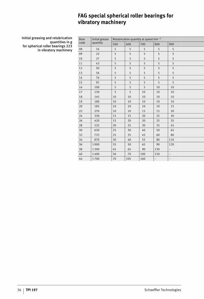
This prevents excessive working and the associated temperature development. The grease in the housing cavities acts as a reservoir and contributes to a longer operating life in accordance withthe operating and the mounting conditions. It is recommended that relubrication should be carried out via the lubrication groove andthe three lubrication holes that are present as standard in the outer ring of all FAG special spherical roller bearings.This ensures uniform supply of lubricant to both rows of rollers. Where rolling bearings are relubricated from the side, the distance between the housing wall and the end face of the bearing should be as small as possible so that the grease can reach the bearing interior quickly and without losses. The grease outlet hole should be located on the opposite side of the bearing.In bearing arrangements for vibratory machinery, it is advisableto relubricate the bearings with small quantities of grease at short intervals. The relubrication quantities are stated as a functionof the bearing size and the speed, see table, page 36.These relubrication quantities relate to a relubrication intervalof 50 operating hours and normal operating temperatures.If continuous relubrication is carried out by means of a central lubricant supply system, the requisite grease quantity m1 per hour and per bearing can be determined using the following equation:
m1 g/hRequisite grease quantityD mmBearing outside diameterB mmBearing width.
The labyrinth seals should be relubricated once per week, or more frequently if operating conditions are unfavourable (heavy exposure to dust, moisture, high operating temperature). The grease should be the same as that used in the rolling bearings.
FAG special spherical roller bearings for vibratory machinery
36 TPI 197 Schaeffler Technologies
Initial greasing and relubricationquantities in g
for spherical roller bearings 223in vibratory machinery
Borecode
Initial grease quantity
Relubrication quantity at speed min–1
500 600 700 800 900
08 16 5 5 5 5 5
09 22 5 5 5 5 5
10 27 5 5 5 5 5
11 43 5 5 5 5 5
12 50 5 5 5 5 5
13 56 5 5 5 5 5
14 76 5 5 5 5 5
15 91 5 5 5 5 5
16 100 5 5 5 10 10
17 130 5 5 10 10 10
18 145 10 10 10 10 10
19 180 10 10 10 10 10
20 185 10 10 10 10 15
22 270 10 10 15 15 20
24 330 15 15 20 25 30
26 420 15 20 20 25 35
28 525 20 25 30 35 45
30 630 25 30 40 50 65
32 725 25 35 45 60 80
34 870 30 40 55 80 110
36 1 000 35 50 65 90 120
38 1 200 45 65 90 130 –
40 1 400 50 70 100 150 –
44 1 700 70 105 160 – –

Schaeffler Technologies TPI 197 37
1 000 1 200 1 400 1 600 1 800 2 000 2 200 2 400 2 600 2 800 3 000 3 200
5 5 5 5 5 5 5 5 5 5 5 5
5 5 5 5 5 5 5 5 5 5 10 10
5 5 5 5 5 5 5 10 10 10 10 15
5 5 5 5 5 10 10 10 10 15 15 20
5 5 5 5 10 10 10 10 15 15 – –
5 5 10 10 10 10 15 15 20 – – –
5 10 10 10 15 15 20 25 – – – –
5 10 10 10 15 20 25 – – – – –
10 10 10 15 20 25 – – – – – –
10 10 15 20 25 35 – – – – – –
10 15 20 25 30 40 – – – – – –
15 15 25 35 45 – – – – – – –
15 20 30 40 – – – – – – – –
20 30 50 70 – – – – – – – –
35 55 85 – – – – – – – – –
40 65 – – – – – – – – – –
60 100 – – – – – – – – – –
90 – – – – – – – – – – –
100 – – – – – – – – – – –
140 – – – – – – – – – – –
– – – – – – – – – – – –
– – – – – – – – – – – –
– – – – – – – – – – – –
– – – – – – – – – – – –

38 TPI 197 Schaeffler Technologies
FAG special spherical roller bearings for vibratory machinery
Oil lubrication If the speeds are above the normal range for grease lubrication, in other words with a speed parameter n · dM � 300 000 min–1 · mm, oil lubrication must be provided. Oil lubrication may also be necessary if there is heating by external sources or for reasons of maintenance. For lubrication of bearings, we recommend mineral oils or synthetic oils with EP (extreme pressure) and anti-corrosion additives, see page 42. Good quality multi-grade oils can also be used. The viscosity ratio should be � = �/�1 � 2.
Oil sump lubrication(bath lubrication)
Oil sump lubrication is normally used up to a speed parameter n · dM = 300 000 min–1 · mm; with frequent oil changes, it can be used up to n · dM = 500 000 min–1 · mm. In this lubrication method, the lubricant is conveyed to the rolling contact points by any gears, the imbalance mass or the rolling elements themselves.The oil level in the machine or bearing housing must be sufficiently high that the gears or imbalance masses are dipped in the oil and create a swirling effect. When the bearing is stationary, the lowest roller must be half immersed in the oil, Figure 15 und table, page 39.
� Normal oil level� Lowest oil level
Figure 15Determining the oil level
at standstill 000A
63D
500
0A63
D5

Schaeffler Technologies TPI 197 39
Oil level at standstill Bore code Bearing series 223
Oil level
Normal Low
mm mm
08 31 34
09 35 38
10 39 42
11 42 46
12 46 50
13 50 54
14 54 59
15 58 62
16 62 67
17 66 71
18 69 74
19 72 78
20 78 84
22 86 94
24 93 101
26 100 109
28 107 117
30 115 125
32 122 133
34 129 140
36 137 149
38 144 156
40 152 165
44 168 182
48 182 195
52 196 211
56 212 228

40 TPI 197 Schaeffler Technologies
FAG special spherical roller bearings for vibratory machinery
A sufficiently large oil quantity will extend the oil change interval.If the cavities in the housings are not sufficient, the shaft guard tube between the bearings can also be used as an oil reservoir oran additional container can be provided. The oil change interval is dependent on the contamination and the ageing condition of the oil.Guide values for the oil quantity and oil change intervals asa function of the bearing bore are given in Figure 16.We recommend regular oil inspection, since the results of such inspections will allow more precise determination of oil change intervals.
Further information ■ TPI 176, Lubrication of Rolling Bearings.
d = bearing boreV = oil quantity
� Oil change interval2 months to 3 months� Oil change interval
10 months to 12 months
Figure 16Oil quantity and oil change interval
as a functionof bearing bore diameter 00
0A63
BF00
0A63
BF

Schaeffler Technologies TPI 197 41
Recirculating oil lubrication If the speed parameter is higher than the permissible valuefor bath lubrication or where special conditions apply (increased heat dissipation required, insufficiently large oil cavities), recirculating oil lubrication must be used. The oil should be fedvia the lubrication groove and lubrication holes in the bearingouter ring. Guide values for normal oil flow rates can be taken from Figure 17. In order to prevent oil backing up in the lubrication sys-tem, the cross-sections of the unpressurised return ducts must be adapted to the cross-sections of the feed ducts (4 to 5 times larger). In recirculating oil lubrication, it is absolutely essential that a filter is provided for retaining wear particles and contaminants in order to prevent impairment of the bearing operating life. Through evaluation of regular oil inspections, the oil change intervals can be matched more accurately to the operating conditions.
V = oil flow quantityD = bearing outside diameter
Figure 17Minimum oil flow rate
for spherical roller bearingsof series 223 in vibratory machinery 00
0A63
DF
000A
63D
F

42 TPI 197 Schaeffler Technologies
FAG special spherical roller bearings for vibratory machinery
Recommended lubricants This section describes greases and oils for vibrating screen bearing arrangements.
Greases for vibrating screen bearingarrangements
Each delivery of the FAG rolling bearing greases Arcanol is subjected to comprehensive quality inspection. The quality of each batch can be clearly demonstrated and identified.Greases for normal temperatures:■ Arcanol MULTITOP
■ Arcanol LOAD400■ Arcanol LOAD220■ Arcanol VIB3.Greases for high temperatures:■ Arcanol TEMP120.In the case of greases that have not been subjected to our incoming goods inspection, we cannot make any statements regarding batch fluctuations, formulation changes or production influences.
Oils for vibrating screen bearingarrangements
If oils are to be used for this application, it must be demonstrated that the additives package is effective in the rolling bearing.In principle, it is possible to use mineral oils and synthetic oils,with the exception of silicone oils. It is not advisable to use oilswith viscosity index improvement agents.

Schaeffler Technologies TPI 197 43
Monitoringof vibrating screens
Vibration diagnosis is a reliable method for identifying the startof machine damage at an early stage. Schaeffler offers monitoring systems that can also be used under very aggressive environmental conditions.Monitoring systems for vibrating screens detect machinery damage at a very early stage. Since the alarm is raised at an early stage,they help to prevent unplanned downtime. Measurement datacan be retrieved on site or remotely at any time and assessed bythe actual customer or by the Schaeffler Remote Service Center, Figure 18 and Figure 19, page 44.By monitoring the vibrating screens, the following system conditions, for example, can be identified:■ bearing damage■ loose parts■ broken springs■ overloads■ impact/contact.Furthermore, the Schaeffler portfolio in the area of maintenance and quality assurance includes other products and services:from mounting, through plant monitoring to the introduction and implementation of preventive maintenance activities.A wide range of mounting and alignment tools, measuring instruments and lubricants, as well as training courses makes maintenance work easier and work processes more efficient.Based on many years’ experience and qualified experts, Schaeffleris the competent partner for customer-oriented solutions relatingto the life cycle of rolling bearings.

44 TPI 197 Schaeffler Technologies
FAG special spherical roller bearings for vibratory machinery
Further information ■ www.schaeffler.com/services■ Or send an e-mail to
Figure 18Vibrating screen
000A
5F13
000A
5F13
Figure 19Schaeffler Remote Service Center
0001
8BEB
0001
8BEB

Schaeffler Technologies TPI 197 45

46 TPI 197 Schaeffler Technologies
FAG special spherical roller bearingsfor vibratory machineryWith cylindrical boreSeries 223..-E1-XL-T41A(D)Series 223..-BE-XL-JPA-T41A
Dimensions
000A
63E9
000A
63E9
Dimension table · Dimensions in mm
Designation Mass Dimensions
m d D B r ns D1 d2
� kg min. � �22308-E1-XL-T41A 1,05 40 90 33 1,5 6,5 76 52,4
22309-E1-XL-T41A 1,39 45 100 36 1,5 6,5 84,7 58,9
22310-E1-XL-T41A 1,9 50 110 40 2 6,5 92,6 63
22311-E1-XL-T41A 2,27 55 120 43 2 6,5 101,4 68,9
22312-E1-XL-T41A 2,97 60 130 46 2,1 6,5 110,1 74,8
22313-E1-XL-T41A 3,57 65 140 48 2,1 9,5 119,3 83,2
22314-E1-XL-T41A 4,21 70 150 51 2,1 9,5 128 86,7
22315-E1-XL-T41A 5,38 75 160 55 2,1 9,5 136,3 92,4
22316-E1-XL-T41A 6,27 80 170 58 2,1 9,5 145,1 98,3
22317-E1-XL-T41D 7,06 85 180 60 3 9,5 154,2 104,4
22318-E1-XL-T41D 8,69 90 190 64 3 12,2 162,5 110,2
22319-E1-XL-T41D 9,69 95 200 67 3 12,2 171,2 116
22320-E1-XL-T41D 13,1 100 215 73 3 12,2 184,7 130,2
22322-E1-XL-T41D 17,7 110 240 80 3 15 204,9 143,1
22324-E1-XL-T41D 22,3 120 260 86 3 15 222,4 150,8
22326-E1-XL-T41D 28 130 280 93 4 17,7 239,5 162,2
22328-E1-XL-T41D 34,6 140 300 102 4 17,7 255,7 173,5
22330-E1-XL-T41D 42,2 150 320 108 4 17,7 273,2 185,3
22332-BE-XL-JPA-T41A 48,4 160 340 114 4 17,7 286,7 201,2
22334-BE-XL-JPA-T41A 58,2 170 360 120 4 17,7 303,9 213,1
22336-BE-XL-JPA-T41A 68,1 180 380 126 4 23,5 320,8 224,9
22338-BE-XL-JPA-T41A 78,9 190 400 132 5 23,5 338,1 236,8
22340-BE-XL-JPA-T41A 89,4 200 420 138 5 23,5 355,1 248,8
22344-BE-XL-JPA-T41A 117 220 460 145 5 23,5 391,1 273,4

Schaeffler Technologies TPI 197 47
Basic load ratings Fatigue limit load Limiting speed Reference speed
dyn.Cr
stat.C0r
Cur nG nB
kN kN kN min–1 min–1
156 149 13,1 7 600 5 500
187 183 16 6 800 5 000
229 223 20,1 6 300 4 800
265 260 23,9 5 800 4 500
310 310 28 5 400 4 200
350 365 32,5 5 000 3 800
390 390 36,5 4 800 3 700
445 450 40,5 4 500 3 550
495 510 45 4 250 3 400
540 560 49,5 4 100 3 200
610 630 55 3 850 3 000
670 700 59 3 700 2 800
810 920 75 3 300 2 380
950 1 070 90 3 000 2 130
1 080 1 170 102 2 850 2 000
1 250 1 370 116 2 650 1 820
1 460 1 630 131 2 420 1 660
1 640 1 850 147 2 290 1 520
1 680 1 990 157 2 250 1 420
1 870 2 220 173 2 130 1 320
2 060 2 460 190 2 030 1 230
2 220 2 650 207 1 940 1 160
2 440 2 950 225 1 830 1 080
2 800 3 400 265 1 690 950
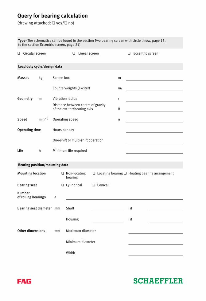
Query for bearing calculation(drawing attached: ❑ yes/❑ no)
Type (The schematics can be found in the section Two bearing screen with circle throw, page 15,to the section Eccentric screen, page 21)
❑ Circular screen ❑ Linear screen ❑ Eccentric screen
Load duty cycle/design data
Masses kg Screen box m
Counterweights (exciter) m1
Geometry m Vibration radius r
Distance between centre of gravityof the exciter/bearing axis R
Speed min–1 Operating speed n
Operating time Hours per day
One-shift or multi-shift operation
Life h Minimum life required
Bearing position/mounting data
Mounting location ❑ Non-locating bearing
❑ Locating bearing ❑ Floating bearing arrangement
Bearing seat ❑ Cylindrical ❑ Conical
Numberof rolling bearings z
Bearing seat diameter mm Shaft Fit
Housing Fit
Other dimensions mm Maximum diameter
Minimum diameter
Width

Query for bearing calculation(drawing attached: ❑ yes/❑ no)
Environmental influence
Ambient temperature °C
Material in box(screen for hot materials) °C
Operating temperature °C
Humidity %
Dust ❑ Heavy ❑ Moderate ❑ Little/none
Chemical influences ❑ Yes ❑ No
Installation area ❑ Hall ❑ Outdoors
Lubrication
❑ Grease ❑ Oil sump ❑ Oil recirculation ❑ Oil mist lubrication
Sealing
❑ Labyrinths that can be relubricated with V ring seals
❑ Oil splash rings and oil collector grooves
Other guidelines

Schaeffler TechnologiesAG & Co. KG
Georg-Schäfer-Straße 3097421 SchweinfurtGermanyInternet www.schaeffler.de/enE-mail [email protected]
In Germany:Phone 0180 5003872Fax 0180 5003873
From other countries:Phone +49 9721 91-0Fax +49 9721 91-3435
Every care has been taken to ensure the
correctness of the information contained
in this publication but no liability can
be accepted for any errors or omissions.
We reserve the right to make technical
changes.
© Schaeffler Technologies AG & Co. KG
Issued: 2017, November
This publication or parts thereof may not
be reproduced without our permission.
TPI 197 GB-DTPI 1
97 /
GB-
D /
201
7111
/ P
rinte
d in
Ger
man
y by
pm
s