fag rolling bearings in rolling mills - schaeffler group · pdf fileschaeffler has for many...
TRANSCRIPT
FAG Rolling Bearings in Rolling Mills


Schaeffler has for many yearsworked on the design and pro -duction of bearings for rolling millsand gathered extensive experiencein this field. This is presented inthe present publication. A designerof rolling mills will find here the principles for selection and calculation of roll neck bearings.Their mounting and maintenance is also covered in detail. For anyquestions not covered under these principles, the Schaefflerengineering service can provideassistance. The dimensions andperformance data of rolling bearingsfor rolling mills are given in Catalogue GL1. A selection of publications covering rolling mill bearing arrangements and fundamental subjects in bearingarrangement engineering, such as dimensioning, mounting anddismounting, lubrication and maintenance is given in the list on page 52 of this publication.
Foreword
Contents
Roll neck bearings 4Design conditions 4Cylindrical roller bearings 5Axial bearings 6Tapered roller bearings 7Spherical roller bearings 9Axial tapered roller bearings for screw-down mechanisms 9
Calculation of bearing load 10Self-aligning chocks 10
Strip rolling 10Groove rolling 11
Rigid chocks 12Calculation of roll deflection 13Calculation of load conditions and pressures 14
Load carrying capacity and life 16Bearings under static loading 16Bearings under dynamic loading 16
Lubrication 18Lubrication of roll neck bearings 18Grease lubrication 18
Selection of grease according to loading 19Influence of bearing type 19Influence of speed 19Base oil viscosity 20Viscosity ratio 20Influence of temperature 21Other operating conditions 22
Oil lubrication 23Viscosity requirements 23Other demands on the oil 23Methods of oil lubrication 23
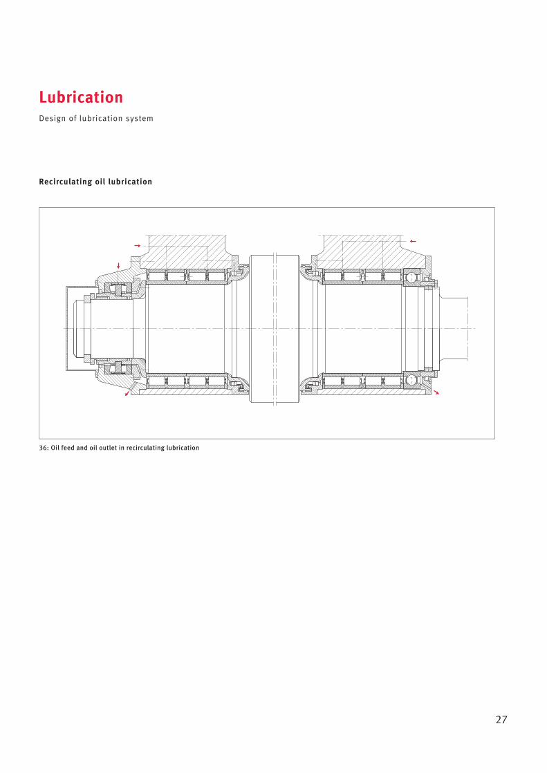
Design of lubrication system 24Fill quantity with grease lubrication 24Relubrication intervals with grease lubrication 24Lubricant feed 24Grease lubrication 24Pneumatic oil lubrication 26Recirculating oil lubrication 27
Tolerances of roll neck bearings 28
Adjacent parts 29Guidelines for fits 29
Radial bearings 29Axial bearings 29
Machining tolerances for cylindrical bearing seats 32Roughness of bearing seats 33Tolerances of roll necks and chocks 34Conditions for inner rings with loose fits 36Chocks 36
Contact surfaces for stand windows and chocks 37Design of seals 37
Mounting and maintenance 38Preparations for mounting 38
Inspection of cylindrical roll necks 38Inspection of chocks 38Surface roughness 38Treatment of bearing seats 39Preparation of bearings for mounting 39
Mounting of four-row cylindrical roller bearings 39Mounting of inner rings 40Mounting of outer rings 41Mounting of axial bearings 42Mounting of preassembled chocks on roll necks 42Dismounting of bearing arrangement 43Loose fit of inner rings 43
Mounting of four-row tapered roller bearings 44Mounting 44Dismounting 46Maintenance 46
Mounting of spherical roller bearings 47Mounting of spherical roller bearings with tapered bore 47Dismounting of spherical roller bearings with tapered bore 47
Stockholding 48Statistical recording 48Industrial Service 48Storage of rolling bearings 49
Selection of further FAG publications 52
Design conditions
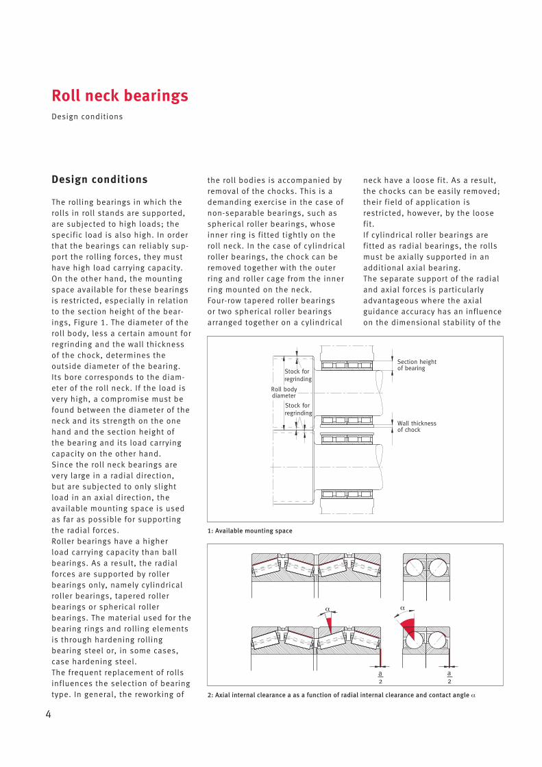
The rolling bearings in which therolls in roll stands are supported,are subjected to high loads; thespecific load is also high. In orderthat the bearings can reliably sup-port the rolling forces, they musthave high load carrying capacity.On the other hand, the mountingspace available for these bearingsis restricted, especially in relationto the section height of the bear-ings, Figure 1. The diameter of theroll body, less a certain amount forregrinding and the wall thicknessof the chock, determines the outside diameter of the bearing.Its bore corresponds to the diam -eter of the roll neck. If the load isvery high, a compromise must befound between the diameter of theneck and its strength on the onehand and the section height of the bearing and its load carryingcapacity on the other hand.Since the roll neck bearings arevery large in a radial direction, but are subjected to only slightload in an axial direction, theavailable mounting space is usedas far as possible for supportingthe radial forces.Roller bearings have a higher load carrying capacity than ballbearings. As a result, the radialforces are supported by rollerbearings only, namely cylindricalroller bearings, tapered rollerbearings or spherical roller bearings. The material used for thebearing rings and rolling elementsis through hardening rolling bearing steel or, in some cases,case hardening steel.The frequent replacement of rollsinfluences the selection of bearingtype. In general, the reworking of
the roll bodies is accompanied byremoval of the chocks. This is ademanding exercise in the case ofnon-separable bearings, such asspherical roller bearings, whoseinner ring is fitted tightly on theroll neck. In the case of cylindricalroller bearings, the chock can beremoved together with the outerring and roller cage from the innerring mounted on the neck.Four-row tapered roller bearings or two spherical roller bearingsarranged together on a cylindrical
Roll neck bearingsDesign conditions
4
neck have a loose fit. As a result,the chocks can be easily removed;their field of application isrestricted, however, by the loosefit.If cylindrical roller bearings are fitted as radial bearings, the rollsmust be axially supported in anadditional axial bearing. The separate support of the radialand axial forces is particularlyadvantageous where the axialguidance accuracy has an influenceon the dimensional stability of the
1: Available mounting space
2: Axial internal clearance a as a function of radial internal clearance and contact angle α
a2
a2
Wall thicknessof chock
Section heightof bearing
Roll bodydiameter
Stock for regrinding
Stock for regrinding
rolled stock, for example in standsfor rolling of shape sections. Axial bearings give a very highguidance accuracy, since they canbe fitted with very small axialinternal clearance or even withoutclearance. In contrast, radial bearings used to provide both
axial and radial guidance alwayshave a larger axial internal clearance. Figure 2 (page 4) shows how theaxial internal clearance a for a given radial internal clearance isdependent on the contact angle α.The ratio between the axial
Roll neck bearingsDesign conditions · Cylindrical roller bearings
5
internal clearance and the radialinternal clearance is at its largestin the case of spherical roller bearings. The values are smaller infour-row tapered roller bearings. The ratio is even smaller in thecase of angular contact ball bearings.
Cylindrical roller bearings
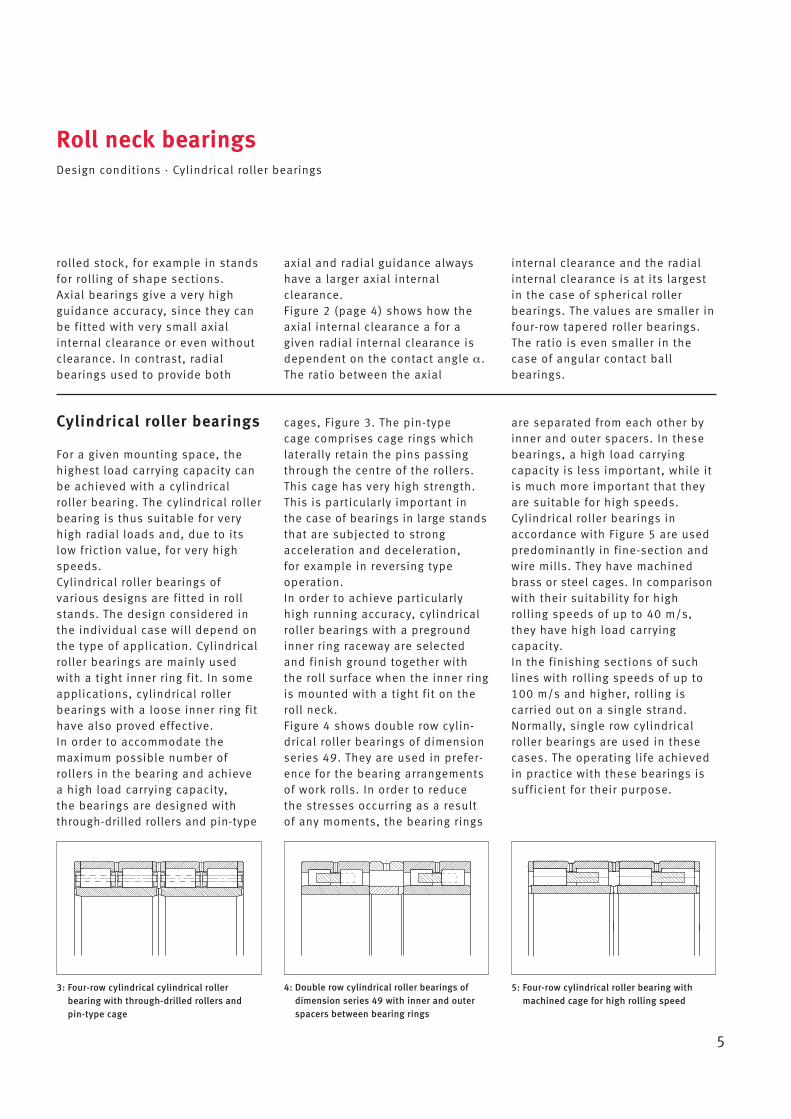
For a given mounting space, thehighest load carrying capacity canbe achieved with a cylindricalroller bearing. The cylindrical rollerbearing is thus suitable for veryhigh radial loads and, due to itslow friction value, for very highspeeds.Cylindrical roller bearings of various designs are fitted in rollstands. The design considered inthe individual case will depend onthe type of application. Cylindricalroller bearings are mainly usedwith a tight inner ring fit. In someapplications, cylindrical rollerbearings with a loose inner ring fithave also proved effective.In order to accommodate the maximum possible number ofrollers in the bearing and achievea high load carrying capacity, the bearings are designed withthrough-drilled rollers and pin-type
cages, Figure 3. The pin-type cage comprises cage rings whichlaterally retain the pins passingthrough the centre of the rollers.This cage has very high strength.This is particularly important inthe case of bearings in large standsthat are subjected to strong acceleration and deceleration, for example in reversing type operation. In order to achieve particularlyhigh running accuracy, cylindricalroller bearings with a pregroundinner ring raceway are selectedand finish ground together withthe roll surface when the inner ringis mounted with a tight fit on theroll neck. Figure 4 shows double row cylin-drical roller bearings of dimensionseries 49. They are used in prefer-ence for the bearing arrangementsof work rolls. In order to reducethe stresses occurring as a resultof any moments, the bearing rings
are separated from each other byinner and outer spacers. In thesebearings, a high load carryingcapacity is less important, while itis much more important that theyare suitable for high speeds. Cylindrical roller bearings in accordance with Figure 5 are usedpredominantly in fine-section andwire mills. They have machinedbrass or steel cages. In comparisonwith their suitability for highrolling speeds of up to 40 m/s,they have high load carryingcapacity.In the finishing sections of suchlines with rolling speeds of up to100 m/s and higher, rolling is carried out on a single strand. Normally, single row cylindricalroller bearings are used in thesecases. The operating life achievedin practice with these bearings issufficient for their purpose.
3: Four-row cylindrical cylindrical roller bearing with through-drilled rollers andpin-type cage
4: Double row cylindrical roller bearings ofdimension series 49 with inner and outerspacers between bearing rings
5: Four-row cylindrical roller bearing withmachined cage for high rolling speed
Axial bearings
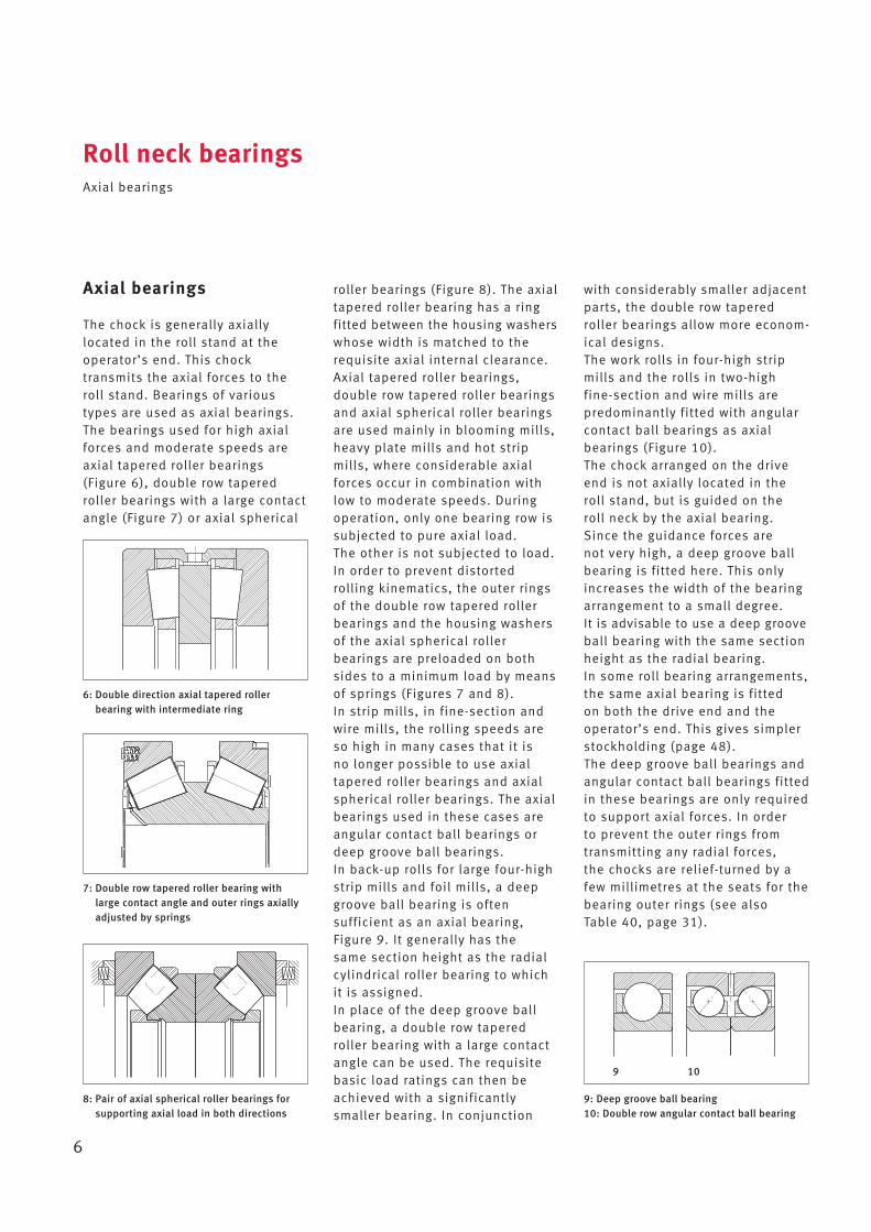
The chock is generally axiallylocated in the roll stand at theoperator’s end. This chock transmits the axial forces to theroll stand. Bearings of varioustypes are used as axial bearings.The bearings used for high axialforces and moderate speeds areaxial tapered roller bearings (Figure 6), double row taperedroller bearings with a large contactangle (Figure 7) or axial spherical
roller bearings (Figure 8). The axialtapered roller bearing has a ringfitted between the housing washerswhose width is matched to the requisite axial internal clearance.Axial tapered roller bearings, double row tapered roller bearingsand axial spherical roller bearingsare used mainly in blooming mills,heavy plate mills and hot stripmills, where considerable axialforces occur in combination withlow to moderate speeds. Duringoperation, only one bearing row issubjected to pure axial load. The other is not subjected to load.In order to prevent distortedrolling kinematics, the outer ringsof the double row tapered rollerbearings and the housing washersof the axial spherical roller bearings are preloaded on bothsides to a minimum load by meansof springs (Figures 7 and 8).In strip mills, in fine-section andwire mills, the rolling speeds areso high in many cases that it is no longer possible to use axialtapered roller bearings and axialspherical roller bearings. The axialbearings used in these cases areangular contact ball bearings ordeep groove ball bearings. In back-up rolls for large four-highstrip mills and foil mills, a deepgroove ball bearing is often sufficient as an axial bearing, Figure 9. It generally has the same section height as the radialcylindrical roller bearing to whichit is assigned.In place of the deep groove ballbearing, a double row taperedroller bearing with a large contactangle can be used. The requisitebasic load ratings can then beachieved with a significantlysmaller bearing. In conjunction
Roll neck bearingsAxial bearings
6
with considerably smaller adjacentparts, the double row taperedroller bearings allow more econom-ical designs.The work rolls in four-high stripmills and the rolls in two-high fine-section and wire mills are predominantly fitted with angularcontact ball bearings as axial bearings (Figure 10).The chock arranged on the driveend is not axially located in theroll stand, but is guided on the roll neck by the axial bearing.Since the guidance forces are not very high, a deep groove ballbearing is fitted here. This onlyincreases the width of the bearingarrangement to a small degree. It is advisable to use a deep grooveball bearing with the same sectionheight as the radial bearing.In some roll bearing arrangements,the same axial bearing is fitted on both the drive end and theoperator’s end. This gives simplerstockholding (page 48).The deep groove ball bearings andangular contact ball bearings fittedin these bearings are only requiredto support axial forces. In order to prevent the outer rings fromtransmitting any radial forces, the chocks are relief-turned by afew millimetres at the seats for thebearing outer rings (see also Table 40, page 31).
6: Double direction axial tapered roller bearing with intermediate ring
7: Double row tapered roller bearing withlarge contact angle and outer rings axiallyadjusted by springs
8: Pair of axial spherical roller bearings forsupporting axial load in both directions
9: Deep groove ball bearing10: Double row angular contact ball bearing
9 10
Tapered roller bearings
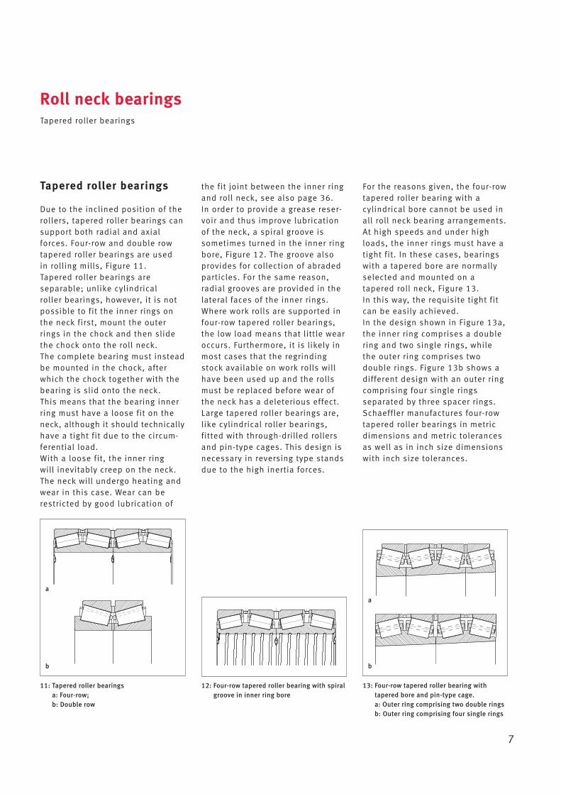
Due to the inclined position of therollers, tapered roller bearings cansupport both radial and axialforces. Four-row and double rowtapered roller bearings are used in rolling mills, Figure 11. Tapered roller bearings are separable; unlike cylindrical roller bearings, however, it is notpossible to fit the inner rings onthe neck first, mount the outerrings in the chock and then slidethe chock onto the roll neck. The complete bearing must insteadbe mounted in the chock, afterwhich the chock together with thebearing is slid onto the neck. This means that the bearing innerring must have a loose fit on theneck, although it should technicallyhave a tight fit due to the circum-ferential load.With a loose fit, the inner ring will inevitably creep on the neck.The neck will undergo heating andwear in this case. Wear can berestricted by good lubrication of
the fit joint between the inner ringand roll neck, see also page 36. In order to provide a grease reser-voir and thus improve lubricationof the neck, a spiral groove issometimes turned in the inner ringbore, Figure 12. The groove alsoprovides for collection of abradedparticles. For the same reason,radial grooves are provided in thelateral faces of the inner rings.Where work rolls are supported infour-row tapered roller bearings,the low load means that little wearoccurs. Furthermore, it is likely inmost cases that the regrindingstock available on work rolls willhave been used up and the rollsmust be replaced before wear ofthe neck has a deleterious effect.Large tapered roller bearings are,like cylindrical roller bearings, fitted with through-drilled rollersand pin-type cages. This design isnecessary in reversing type standsdue to the high inertia forces.
Roll neck bearingsTapered roller bearings
7
For the reasons given, the four-rowtapered roller bearing with a cylindrical bore cannot be used inall roll neck bearing arrangements.At high speeds and under highloads, the inner rings must have atight fit. In these cases, bearingswith a tapered bore are normallyselected and mounted on atapered roll neck, Figure 13. In this way, the requisite tight fitcan be easily achieved. In the design shown in Figure 13a,the inner ring comprises a doublering and two single rings, whilethe outer ring comprises two double rings. Figure 13b shows adifferent design with an outer ringcomprising four single rings separated by three spacer rings.Schaeffler manufactures four-rowtapered roller bearings in metricdimensions and metric tolerancesas well as in inch size dimensionswith inch size tolerances.
11: Tapered roller bearingsa: Four-row; b: Double row
12: Four-row tapered roller bearing with spiralgroove in inner ring bore
13: Four-row tapered roller bearing with tapered bore and pin-type cage. a: Outer ring comprising two double rings b: Outer ring comprising four single rings
a
b
a
b
Sealed multi-row tapered rollerbearings
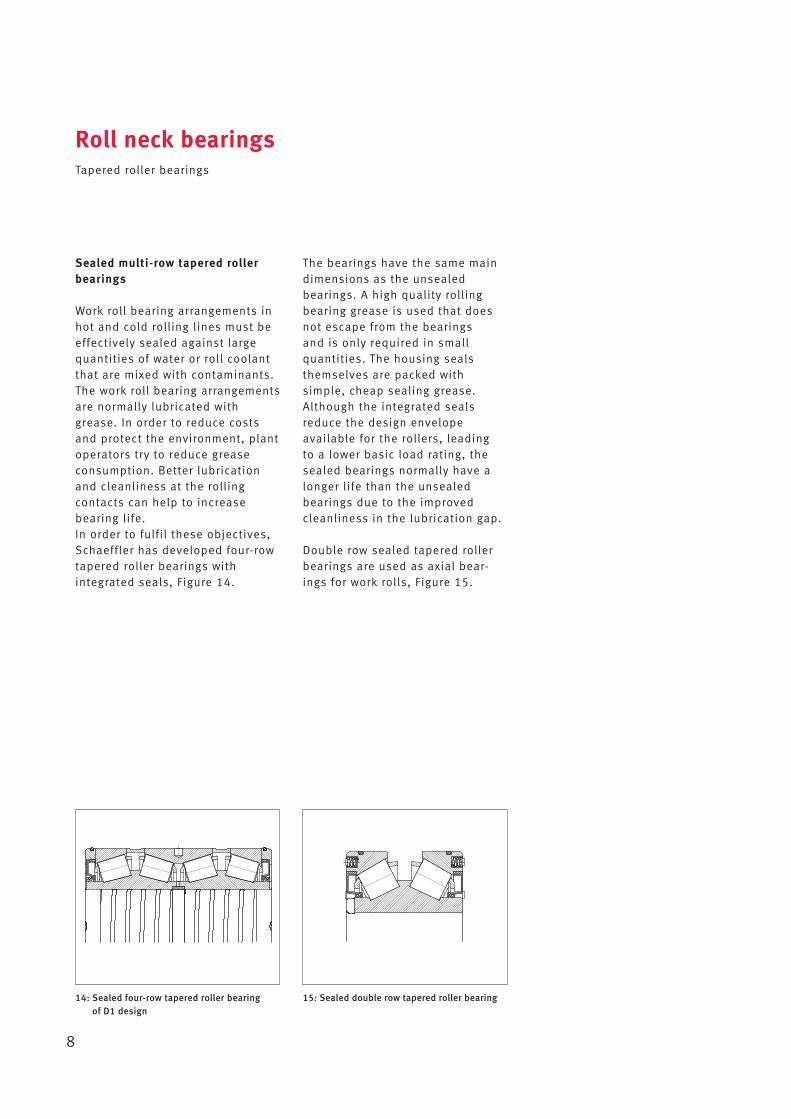
Work roll bearing arrangements inhot and cold rolling lines must beeffectively sealed against largequantities of water or roll coolantthat are mixed with contaminants.The work roll bearing arrangementsare normally lubricated withgrease. In order to reduce costsand protect the environment, plantoperators try to reduce grease consumption. Better lubricationand cleanliness at the rolling contacts can help to increase bearing life.In order to fulfil these objectives,Schaeffler has developed four-rowtapered roller bearings with integrated seals, Figure 14.
The bearings have the same maindimensions as the unsealed bearings. A high quality rollingbearing grease is used that doesnot escape from the bearings and is only required in small quantities. The housing sealsthemselves are packed with simple, cheap sealing grease.Although the integrated sealsreduce the design envelope available for the rollers, leading to a lower basic load rating, thesealed bearings normally have alonger life than the unsealed bearings due to the improvedcleanliness in the lubrication gap.
Double row sealed tapered rollerbearings are used as axial bear-ings for work rolls, Figure 15.
Roll neck bearingsTapered roller bearings
8
14: Sealed four-row tapered roller bearing of D1 design
15: Sealed double row tapered roller bearing
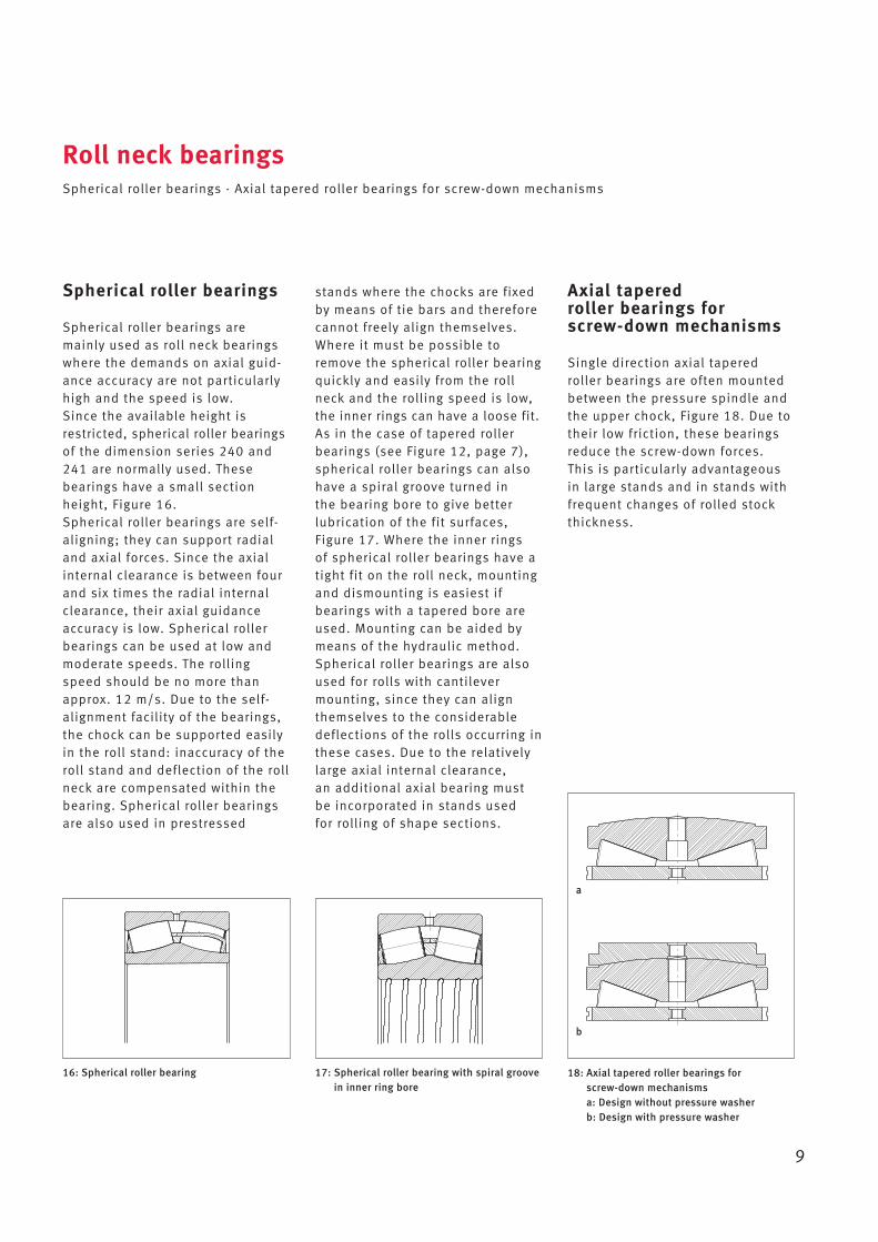
Spherical roller bearings
Spherical roller bearings are mainly used as roll neck bearingswhere the demands on axial guid-ance accuracy are not particularlyhigh and the speed is low. Since the available height isrestricted, spherical roller bearingsof the dimension series 240 and241 are normally used. Thesebearings have a small sectionheight, Figure 16.Spherical roller bearings are self-aligning; they can support radialand axial forces. Since the axialinternal clearance is between fourand six times the radial internalclearance, their axial guidanceaccuracy is low. Spherical rollerbearings can be used at low andmoderate speeds. The rollingspeed should be no more thanapprox. 12 m/s. Due to the self-alignment facility of the bearings,the chock can be supported easilyin the roll stand: inaccuracy of theroll stand and deflection of the rollneck are compensated within thebearing. Spherical roller bearingsare also used in prestressed
stands where the chocks are fixedby means of tie bars and thereforecannot freely align themselves.Where it must be possible toremove the spherical roller bearingquickly and easily from the rollneck and the rolling speed is low,the inner rings can have a loose fit.As in the case of tapered rollerbearings (see Figure 12, page 7),spherical roller bearings can alsohave a spiral groove turned in the bearing bore to give betterlubrication of the fit surfaces, Figure 17. Where the inner rings of spherical roller bearings have atight fit on the roll neck, mountingand dismounting is easiest if bearings with a tapered bore areused. Mounting can be aided bymeans of the hydraulic method.Spherical roller bearings are alsoused for rolls with cantilevermounting, since they can alignthemselves to the considerabledeflections of the rolls occurring inthese cases. Due to the relativelylarge axial internal clearance, an additional axial bearing mustbe incorporated in stands used for rolling of shape sections.
Roll neck bearingsSpherical roller bearings · Axial tapered roller bearings for screw-down mechanisms
9
Axial tapered roller bearings for screw-down mechanisms
Single direction axial taperedroller bearings are often mountedbetween the pressure spindle andthe upper chock, Figure 18. Due totheir low friction, these bearingsreduce the screw-down forces. This is particularly advantageousin large stands and in stands withfrequent changes of rolled stockthickness.
16: Spherical roller bearing 17: Spherical roller bearing with spiral groovein inner ring bore
18: Axial tapered roller bearings for screw-down mechanismsa: Design without pressure washerb: Design with pressure washer
a
b
Calculation of rolling force is generally carried out with the aidof computer programs. A decisiveinfluence is exerted by the type ofrolled stock, the type of rolling(strip or groove rolling) and theproposed rolling schedule. The rolling forces actually occurringsometimes differ considerablyfrom the calculated results if therolling schedule does not corre-spond to the projected schedule.Furthermore, the shocks occurringwhen the rolled stock enters therolls is only considered in approxi-mate terms in the calculation. The rolling force in the initial passmay be more than twice the sub -sequent rolling force. The magni-tude of these initial pass peaks isdependent on the configuration of the rolled stock and the tem -perature of the rolled stock ends. The initial pass peak in rollingforce only occurs for a short time.It is not generally taken into consideration in life calculation. It must not be overlooked, however,that the fatigue life of the rollingbearings is often reduced to a con-siderable extent by such stresses.The distribution of the rolling forceover the two bearing positions isdependent on the design of theroll stand and the type of rolledstock.
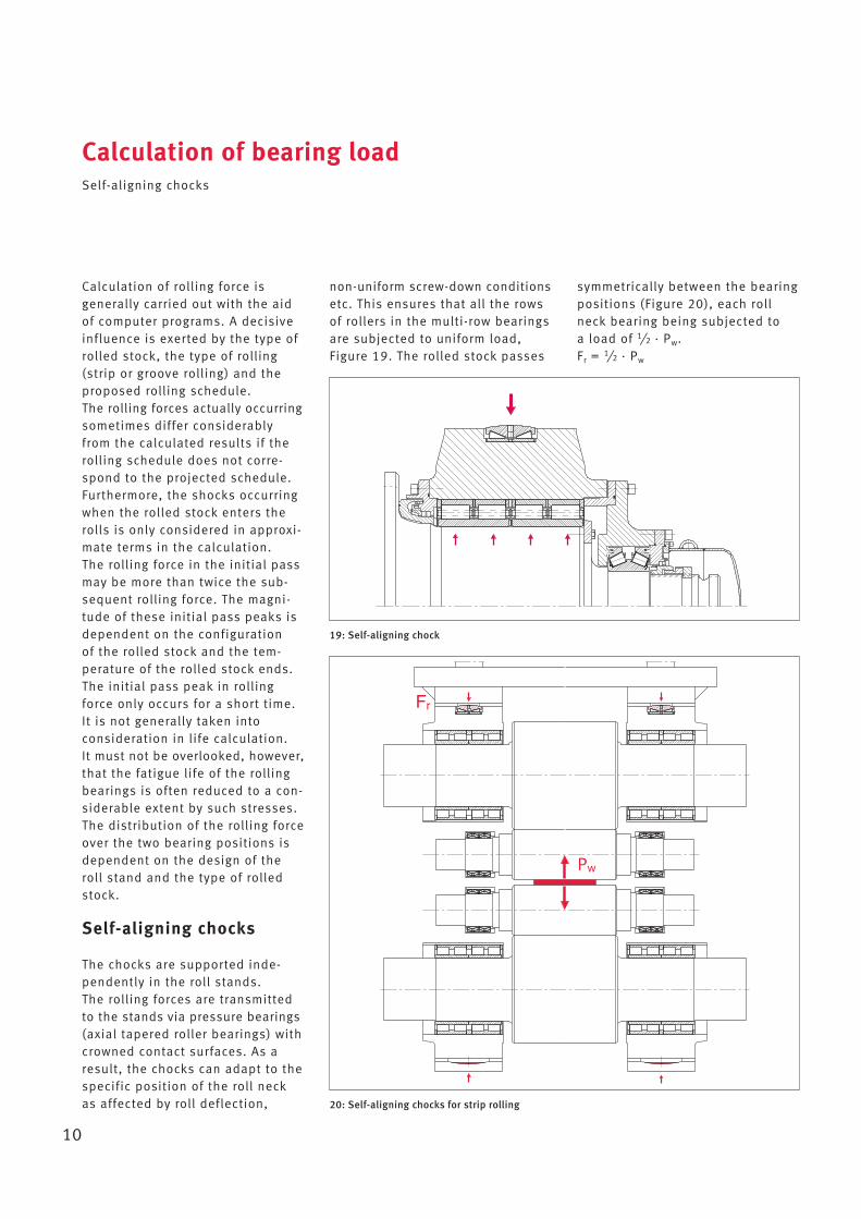
Self-aligning chocks
The chocks are supported inde-pendently in the roll stands. The rolling forces are transmittedto the stands via pressure bearings(axial tapered roller bearings) withcrowned contact surfaces. As aresult, the chocks can adapt to thespecific position of the roll neck as affected by roll deflection,
non-uniform screw-down conditionsetc. This ensures that all the rowsof rollers in the multi-row bearingsare subjected to uniform load, Figure 19. The rolled stock passes
Calculation of bearing loadSelf-aligning chocks
10
symmetrically between the bearingpositions (Figure 20), each rollneck bearing being subjected to a load of 1
/2 · Pw.Fr = 1
/2 · Pw
19: Self-aligning chock
20: Self-aligning chocks for strip rolling
Pw
Fr
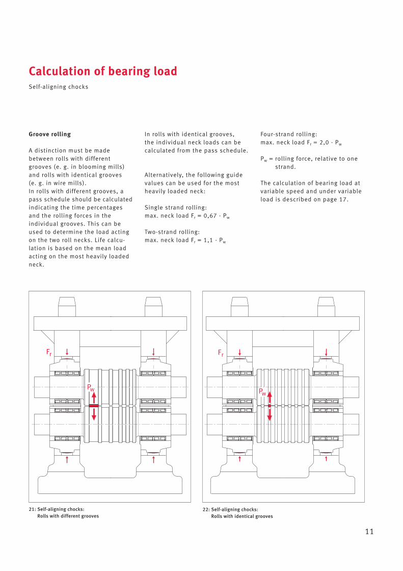
Groove rolling
A distinction must be madebetween rolls with differentgrooves (e. g. in blooming mills)and rolls with identical grooves (e. g. in wire mills).In rolls with different grooves, apass schedule should be calculatedindicating the time percentagesand the rolling forces in the individual grooves. This can beused to determine the load actingon the two roll necks. Life calcu -lation is based on the mean loadacting on the most heavily loadedneck.
In rolls with identical grooves, the individual neck loads can becalculated from the pass schedule.
Alternatively, the following guidevalues can be used for the mostheavily loaded neck:
Single strand rolling:max. neck load Fr = 0,67 · Pw
Two-strand rolling:max. neck load Fr = 1,1 · Pw
Calculation of bearing loadSelf-aligning chocks
11
Four-strand rolling:max. neck load Fr = 2,0 · Pw
Pw = rolling force, relative to onestrand.
The calculation of bearing load atvariable speed and under variableload is described on page 17.
21: Self-aligning chocks:Rolls with different grooves
22: Self-aligning chocks: Rolls with identical grooves
Pw
Fr
Pw
Fr

Rigid chocks
Both bearings are mounted inhousings that are rigidly connec -ted to each other. Roll deflections,neck offsets or misalignmentscause mutual tilting of the twobearing rings. This has no influ-ence on the bearings and their cal-culation if the necks are supportedin spherical roller bearings.In the case of double row or multi-row cylindrical roller bearings, it must be anticipated that there
will be an uneven distribution ofload over the rows of rollers. Themethod developed by Schaefflerfor calculating roll deflection canbe used to determine the load onthe individual rows of rollers. Itmust then be checked whether therow of rollers subjected to higherload has an adequate fatigue life.Rigid chocks are selected predomi-nantly for shape section rolls. The distribution of rolling forceover the two roll necks can be calculated as shown on page 11.
Calculation of bearing loadRigid chocks
12
The upper and lower chock arepressed together by the preloadforce, which means that they cannot adjust to misalignment.This can lead not only to rolldeflection but also to offset of thetwo chocks relative to the roll axis.These stands are predominantlyfitted with spherical roller bearings.If no axial bearing is provided, theaxial force must be accommodatedin the locating bearing.
23: Rigid chocks 24: Prestressed stands
Pw
Fr
Pw
Fr
13
Calculation of roll deflection and load conditions in the rolling bearings
The software Bearinx® can be usedto calculate the deflection behav-iour of elastic rolls under differentload conditions that are supportedby elastic means. The supportreactions, internal stresses in therolling bearings, the comparativestresses in the shafts and themost important calculation resultsare outputted in numerical andgraphical form.
The following influences can beanalysed:
• elasticity of plain and steppedsolid and hollow rolls made fromdifferent materials, deformationdue to shear forces.
• shaft loads due to rolling forcesand bending moments or otherexternal forces acting on thebearings.
• shaft support in the form ofrolling bearings with non-linearelasticity, taking account ofbearing geometry, bearing clearance, rolling element andraceway profiles as well as special conditions in support ofloads.
• creation and calculation of any number of load cases (combinations of load andspeed).
The following calculation resultsare outputted:
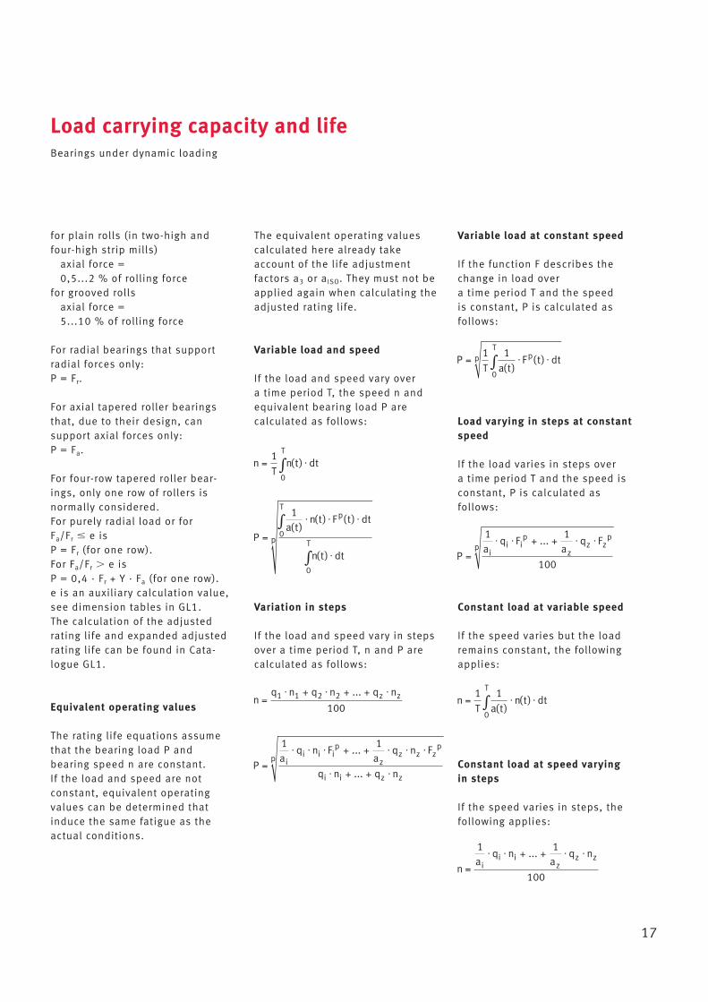
The deflection and inclination ofthe roll axis at any point, the shearforces and bending moments, the stresses, the bearing reactionforces, the bearing elasticity, theload conditions within the rollingbearings and pressure distributionat the rolling contacts of individualrolling elements. Based on thestress calculated for the individualrolling contacts, Bearinx® deter-mines the bearing life to high precision.
Calculation of bearing loadCalculation of roll deflection and load conditions in the rolling bearings
Calculation example for roll deflection and load conditions in the rolling bearings
The subject of calculation is thework roll and back-up roll of afour-high cold rolling mill.
Load:Rolling force Pw = 8 000 kN
During the input operation, the external form of the roll isdescribed. The rolling force can beinputted either as a line load orsplit into individual loads that actat different points on the roll bodydistributed over the width of therolled stock. The chocks are considered as systems into whichforces and/or moments are intro-duced. The self-alignment facilityof the chocks is taken into con -sideration. Cylindrical roller bearings and tapered roller bearings are used as roll neckbearings. They have non-linearspring characteristics.
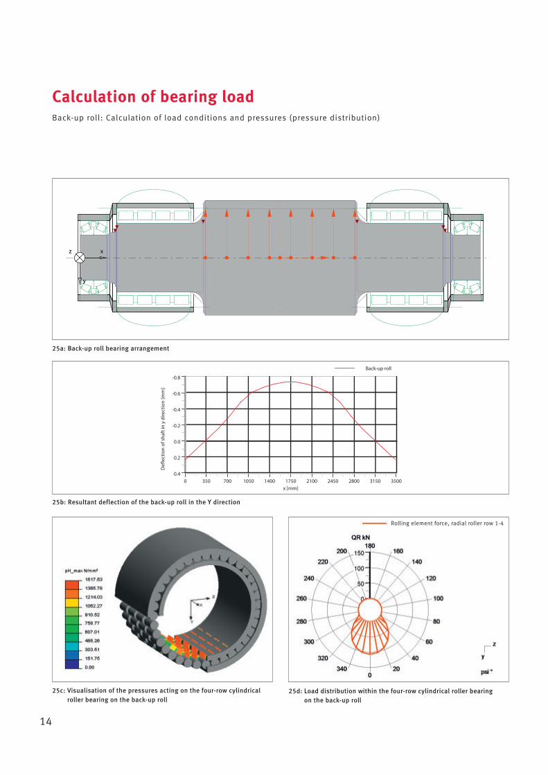
Calculation of bearing loadBack-up roll: Calculation of load conditions and pressures (pressure distribution)
14
25a: Back-up roll bearing arrangement
25c: Visualisation of the pressures acting on the four-row cylindricalroller bearing on the back-up roll
x
y
z x
y
z
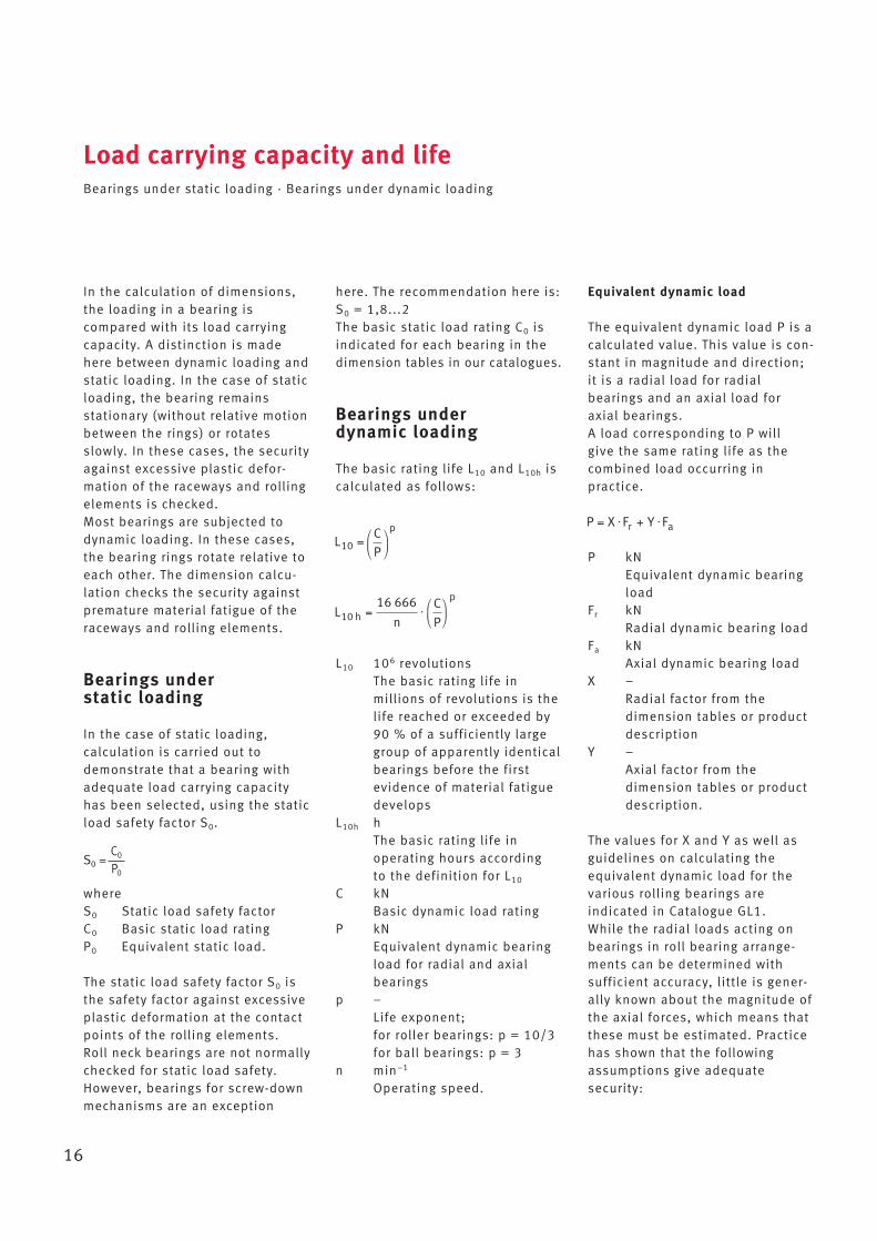
25b: Resultant deflection of the back-up roll in the Y direction
Defl
ectio
n of
sha
ft in
y d
irect
ion
[mm
]
0.4
0.2
0.0
-0.2
-0.4
-0.6
-0.8
x [mm]0 350 700 1050 1400 1750 2100 2450 2800 3150 3500
Back-up roll
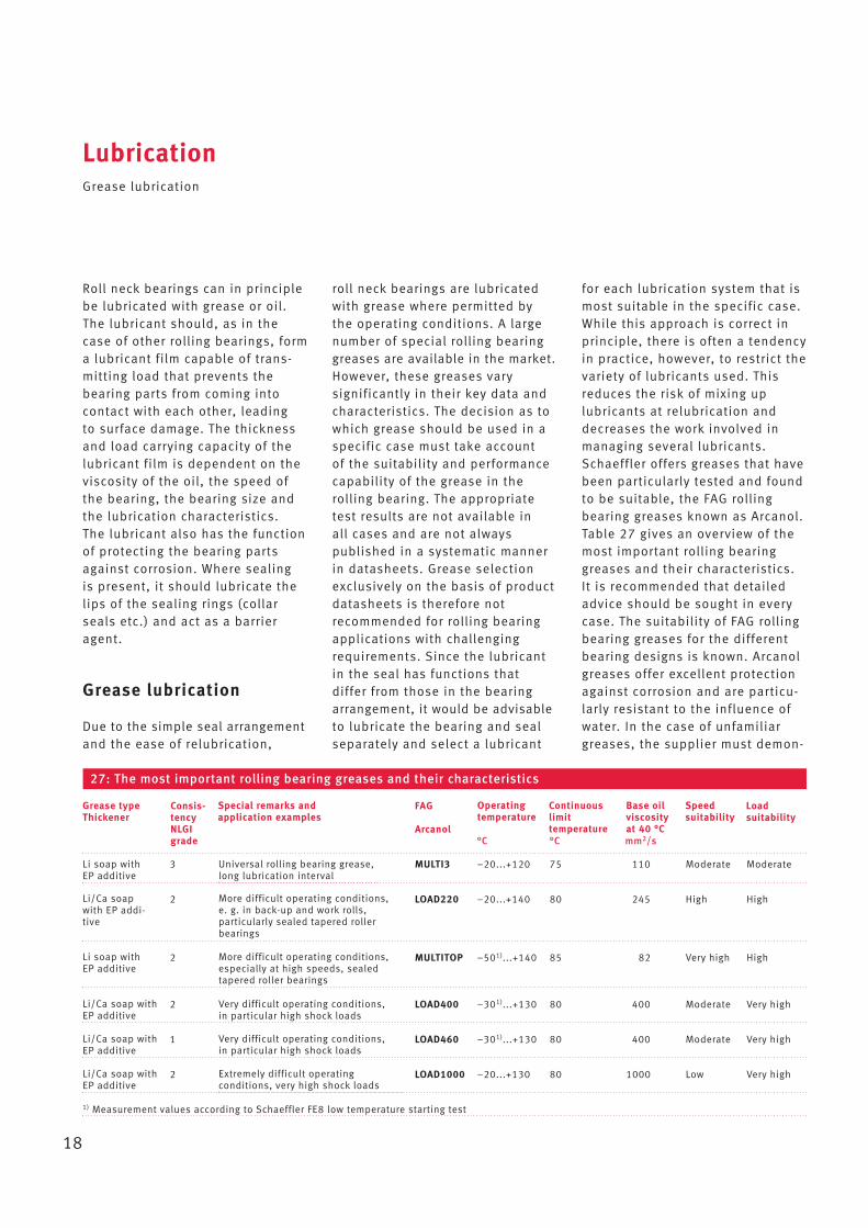
25d: Load distribution within the four-row cylindrical roller bearing on the back-up roll
Rolling element force, radial roller row 1-4

15
Calculation of bearing loadWork roll: Calculation of load conditions and pressures (pressure distribution)
26a: Work roll bearing arrangement
x
y
z x
y
z
26b: Visualisation of the pressures in the four-row tapered roller bearing on the work roll
26c: Load distribution in the four-row tapered roller bearing on the back-up roll
Rolling element force, radial roller row 1 and 3
Rolling element force, radial roller row 2 and 4
16
In the calculation of dimensions,the loading in a bearing is compared with its load carryingcapacity. A distinction is madehere between dynamic loading andstatic loading. In the case of staticloading, the bearing remains stationary (without relative motionbetween the rings) or rotates slowly. In these cases, the securityagainst excessive plastic defor -mation of the raceways and rollingelements is checked.Most bearings are subjected todynamic loading. In these cases,the bearing rings rotate relative toeach other. The dimension calcu -lation checks the security againstpremature material fatigue of theraceways and rolling elements.
Bearings under static loading
In the case of static loading, calculation is carried out todemonstrate that a bearing withadequate load carrying capacityhas been selected, using the staticload safety factor S0.
whereS0 Static load safety factorC0 Basic static load ratingP0 Equivalent static load.
The static load safety factor S0 isthe safety factor against excessiveplastic deformation at the contactpoints of the rolling elements. Roll neck bearings are not normallychecked for static load safety.However, bearings for screw-downmechanisms are an exception
here. The recommendation here is:S0 = 1,8...2The basic static load rating C0 isindicated for each bearing in thedimension tables in our catalogues.
Bearings under dynamic loading
The basic rating life L10 and L10h iscalculated as follows:
L10 106 revolutionsThe basic rating life in millions of revolutions is thelife reached or exceeded by90 % of a sufficiently largegroup of apparently identicalbearings before the first evidence of material fatiguedevelops
L10h hThe basic rating life in operating hours according to the definition for L10
C kNBasic dynamic load rating
P kNEquivalent dynamic bearingload for radial and axialbearings
p –Life exponent; for roller bearings: p = 10/3 for ball bearings: p = 3
n min–1
Operating speed.
Load carrying capacity and lifeBearings under static loading · Bearings under dynamic loading
Equivalent dynamic load
The equivalent dynamic load P is acalculated value. This value is con-stant in magnitude and direction;it is a radial load for radial bearings and an axial load for axial bearings.A load corresponding to P will give the same rating life as thecombined load occurring in practice.
P kNEquivalent dynamic bearingload
Fr kNRadial dynamic bearing load
Fa kNAxial dynamic bearing load
X –Radial factor from the dimension tables or productdescription
Y –Axial factor from the dimension tables or productdescription.
The values for X and Y as well asguidelines on calculating theequivalent dynamic load for thevarious rolling bearings are indicated in Catalogue GL1. While the radial loads acting onbearings in roll bearing arrange-ments can be determined with sufficient accuracy, little is gener-ally known about the magnitude ofthe axial forces, which means thatthese must be estimated. Practicehas shown that the followingassumptions give adequate security:
S0 =C0
P0
17
for plain rolls (in two-high andfour-high strip mills)
axial force = 0,5...2 % of rolling force
for grooved rollsaxial force = 5...10 % of rolling force
For radial bearings that supportradial forces only: P = Fr.
For axial tapered roller bearingsthat, due to their design, can support axial forces only:P = Fa.
For four-row tapered roller bear-ings, only one row of rollers is normally considered.For purely radial load or for Fa/Fr � e isP = Fr (for one row). For Fa/Fr � e isP = 0,4 · Fr + Y · Fa (for one row).e is an auxiliary calculation value,see dimension tables in GL1.The calculation of the adjusted rating life and expanded adjustedrating life can be found in Cata-logue GL1.
Equivalent operating values
The rating life equations assumethat the bearing load P and bearing speed n are constant. If the load and speed are not constant, equivalent operating values can be determined thatinduce the same fatigue as theactual conditions.
The equivalent operating valuescalculated here already takeaccount of the life adjustment factors a3 or aISO. They must not beapplied again when calculating theadjusted rating life.
Variable load and speed
If the load and speed vary over a time period T, the speed n andequivalent bearing load P are calculated as follows:
Variation in steps
If the load and speed vary in stepsover a time period T, n and P arecalculated as follows:
Load carrying capacity and lifeBearings under dynamic loading
Variable load at constant speed
If the function F describes thechange in load overa time period T and the speed is constant, P is calculated as follows:
Load varying in steps at constantspeed
If the load varies in steps over a time period T and the speed isconstant, P is calculated as follows:
Constant load at variable speed
If the speed varies but the loadremains constant, the followingapplies:
Constant load at speed varying in steps
If the speed varies in steps, thefollowing applies:
18
Roll neck bearings can in principlebe lubricated with grease or oil.The lubricant should, as in thecase of other rolling bearings, forma lubricant film capable of trans-mitting load that prevents thebearing parts from coming intocontact with each other, leading to surface damage. The thicknessand load carrying capacity of thelubricant film is dependent on theviscosity of the oil, the speed ofthe bearing, the bearing size andthe lubrication characteristics. The lubricant also has the functionof protecting the bearing partsagainst corrosion. Where sealing is present, it should lubricate thelips of the sealing rings (collarseals etc.) and act as a barrieragent.
Grease lubrication
Due to the simple seal arrangementand the ease of relubrication,
roll neck bearings are lubricated with grease where permitted bythe operating conditions. A largenumber of special rolling bearinggreases are available in the market.However, these greases vary significantly in their key data andcharacteristics. The decision as towhich grease should be used in aspecific case must take account of the suitability and performancecapability of the grease in therolling bearing. The appropriatetest results are not available in all cases and are not always published in a systematic mannerin datasheets. Grease selectionexclusively on the basis of productdatasheets is therefore not recommended for rolling bearingapplications with challengingrequirements. Since the lubricantin the seal has functions that differ from those in the bearingarrangement, it would be advisableto lubricate the bearing and sealseparately and select a lubricant
LubricationGrease lubrication
for each lubrication system that ismost suitable in the specific case.While this approach is correct inprinciple, there is often a tendencyin practice, however, to restrict thevariety of lubricants used. Thisreduces the risk of mixing up lubricants at relubrication anddecreases the work involved inmanaging several lubricants. Schaeffler offers greases that havebeen particularly tested and foundto be suitable, the FAG rollingbearing greases known as Arcanol.Table 27 gives an overview of themost important rolling bearinggreases and their characteristics.It is recommended that detailedadvice should be sought in everycase. The suitability of FAG rollingbearing greases for the differentbearing designs is known. Arcanolgreases offer excellent protectionagainst corrosion and are particu-larly resistant to the influence ofwater. In the case of unfamiliargreases, the supplier must demon-
27: The most important rolling bearing greases and their characteristics
FAG
Arcanol°C °C mm2/s
3 MULTI3 }20...+120 75 110 Moderate Moderate
2 LOAD220 }20...+140 80 245 High High
2 MULTITOP }501)...+140 85 82 Very high High
2 LOAD400 }301)...+130 80 400 Moderate Very high
1 LOAD460 }301)...+130 80 400 Moderate Very high
2 LOAD1000 }20...+130 80 1000 Low Very high
1) Measurement values according to Schaeffler FE8 low temperature starting test
Grease typeThickener
Consis-tencyNLGIgrade
Load suitability
Special remarks andapplication examples
Operatingtemperature
Continuouslimit temperature
Base oilviscosity at 40 °C
Speed suitability
Li/Ca soapwith EP addi-tive
Li soap withEP additive
Li/Ca soap withEP additive
Li/Ca soap withEP additive
Li/Ca soap withEP additive
Very difficult operating conditions,in particular high shock loads
Universal rolling bearing grease,long lubrication interval
More difficult operating conditions,e. g. in back-up and work rolls, particularly sealed tapered rollerbearings
More difficult operating conditions,especially at high speeds, sealedtapered roller bearings
Extremely difficult operating conditions, very high shock loads
Very difficult operating conditions,in particular high shock loads
Li soap withEP additive
19
strate their suitability. If necessary,Schaeffler can carry out tests onsuitability.
Selection of grease according to loading
Greases are produced in variousconsistencies. These are definedas NLGI grades, which are deter-mined by means of worked penetration in accordance with ISO 2137. The higher the NLGIgrade, the harder the grease. For rolling bearings, greases ofNLGI grades 1, 2 and 3 are used inpreference. For the loading profilestypical of rolling mill bearings,greases of grades 2 and 3 shouldbe used in preference. The lubricantmust always contain an additiveformulation that offers effectiveprotection against wear.
Influence of bearing type
A distinction is made betweenpoint contact (ball bearings) and line contact (tapered rollerbearings and cylindrical rollerbearings).
Bearings with point contact
In ball bearings, each overrollingmotion at the rolling contact exertsstress on only a relatively smallvolume of grease. In addition, therolling kinematics of ball bearingsexhibit only relatively small proportions of sliding motion. Thespecific mechanical stress placedon greases in bearings with pointcontact is therefore significantlyless than in bearings with line contact. Typically, greases with abase oil viscosity of ISO VG 100 orgreater are used.
Bearings with line contact
Roller bearings with line contactplace higher requirements on thegrease. Not only is a larger greasequantity at the contact subjected tostress, but increased proportionsof sliding motion in rolling contactand additional rib friction mustalso be expected. This hinders theformation of a lubricant film andcan lead to mixed friction. As acounter measure, greases for bearings with line contact exhibithigher base oil viscosity (ISO VG150 to 460 and, in special cases,even higher). The consistency isnormally NLGI 2.
Influence of speed
Greases have a maximum permiss -ible speed parameter n · dm that isspecific to the design of rollingbearing. This speed parameter ofthe grease should be significantlyhigher than the requisite speed in the application. If the speed
LubricationGrease lubrication
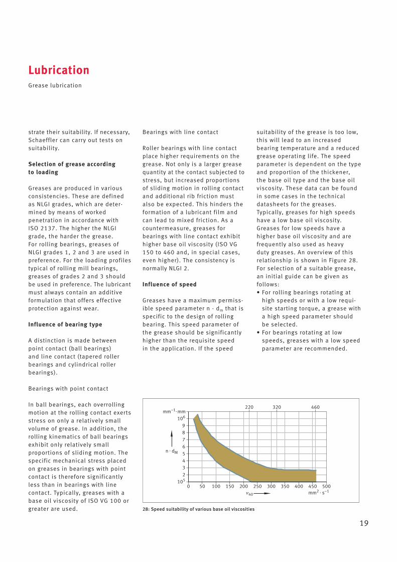
suitability of the grease is too low,this will lead to an increased bearing temperature and a reducedgrease operating life. The speedparameter is dependent on the typeand proportion of the thickener,the base oil type and the base oilviscosity. These data can be foundin some cases in the technicaldatasheets for the greases. Typically, greases for high speedshave a low base oil viscosity.Greases for low speeds have ahigher base oil viscosity and arefrequently also used as heavy duty greases. An overview of thisrelationship is shown in Figure 28.For selection of a suitable grease,an initial guide can be given as follows:• For rolling bearings rotating at
high speeds or with a low requi-site starting torque, a grease witha high speed parameter shouldbe selected.
• For bearings rotating at lowspeeds, greases with a low speedparameter are recommended.
28: Speed suitability of various base oil viscosities
105
106
23456789
50 100 150 200 250 300 350 400 450 5000
220 320 460mm–1� mm
mm2 � s–1�40
n � dM
20
Base oil viscosity
In addition to the speed, the baseoil viscosity has a direct influenceon formation of the lubricant film.In normal cases, the base oil viscosity of the grease shouldtherefore be selected such thatgood lubrication conditions arepresent under the operating mode.The base oil viscosity required inthis case can be estimated withthe aid of the kappa value, wherethe relationship is as follows:� = �/�1. For effective lubricant film forma-tion, the objective should be toachieve kappa values of 2. With kappa values of less than 1,mixed friction must be expected,which leads to wear and premature bearing failure if insufficient
LubricationGrease lubrication
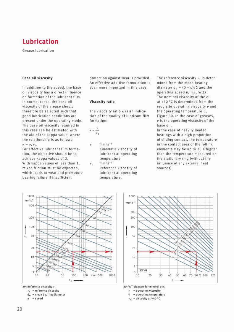
29: Reference viscosity �1
�1 = reference viscosity dM = mean bearing diameter n = speed
10 20 50 100 200 500 10003
5
10
20
50
100
200
500
1000
mm s2
mm
M
n
100000
50000
20000
10000
5000
10002000
500
200
100
50
20
10
5
2
�1
min –1
–1
d �
ISO VG
10 20 30 40 50 60 70 80 100 120°C
10
20
100
200
300
1000
mm s2 –1
�
� 40
1522
3246
68
100
150
220
320460
680
10001500
3
5
50
10
30: V/T diagram for mineral oils� = operating viscosity� = operating temperature�40 = viscosity at +40 °C
protection against wear is provided.An effective additive formulation iseven more important in this case.
Viscosity ratio
The viscosity ratio � is an indica-tion of the quality of lubricant filmformation:
� mm2s–1
Kinematic viscosity of lubricant at operating temperature
�1 mm2s–1
Reference viscosity of lubricant at operating temperature.
The reference viscosity �1 is deter-mined from the mean bearingdiameter dM = (D + d)/2 and theoperating speed n, Figure 29.The nominal viscosity of the oil at +40 °C is determined from therequisite operating viscosity � andthe operating temperature �, Figure 30. In the case of greases, � is the operating viscosity of thebase oil.In the case of heavily loaded bearings with a high proportion of sliding contact, the temperaturein the contact area of the rollingelements may be up to 20 K higherthan the temperature measured onthe stationary ring (without theinfluence of any external heatsources).
21
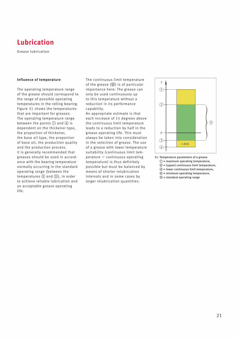
31: Temperature parameters of a grease① = maximum operating temperature,② = (upper) continuous limit temperature,③ = lower continuous limit temperature,④ = minimum operating temperature,⑤ = standard operating range
1
2
4
3
5
0
�20 K
TThe continuous limit temperatureof the grease (②) is of particularimportance here: The grease canonly be used continuously up to this temperature without a red uction in its performance capability.An appropriate estimate is thateach increase of 15 degrees abovethe continuous limit temperatureleads to a reduction by half in thegrease operating life. This mustalways be taken into considerationin the selection of grease. The useof a grease with lower temperaturesuitability (continuous limit tem-perature � continuous operatingtemperature) is thus definitelypossible but must be balanced bymeans of shorter relubricationintervals and in some cases bylarger relubrication quantities.
LubricationGrease lubrication
Influence of temperature
The operating temperature rangeof the grease should correspond tothe range of possible operatingtemperatures in the rolling bearing.Figure 31 shows the temperaturesthat are important for greases. The operating temperature rangebetween the points ① and ④ isdependent on the thickener type,the proportion of thickener, the base oil type, the proportion of base oil, the production qualityand the production process. It is generally recommended thatgreases should be used in accord -ance with the bearing temperaturenormally occurring in the standardoperating range (between the temperatures ② and ③), in orderto achieve reliable lubrication andan acceptable grease operatinglife.
22
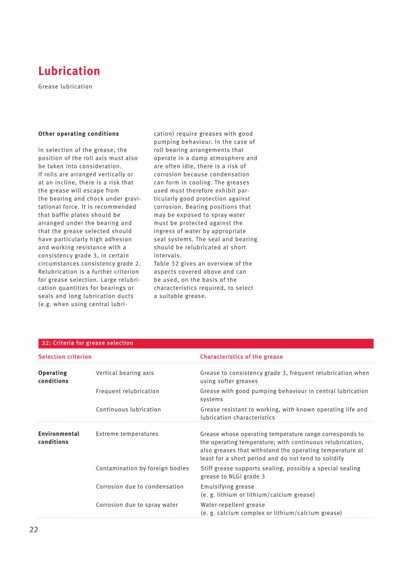
32: Criteria for grease selection
Selection criterion Characteristics of the grease
Operating Vertical bearing axisconditions
Frequent relubrication
Continuous lubrication
Environmental Extreme temperaturesconditions
Contamination by foreign bodies
Corrosion due to condensation
Corrosion due to spray water
Grease to consistency grade 3, frequent relubrication whenusing softer greases
Grease whose operating temperature range corresponds tothe operating temperature; with continuous relubrication,also greases that withstand the operating temperature atleast for a short period and do not tend to solidify
Grease with good pumping behaviour in central lubrication systems
Grease resistant to working, with known operating life andlubrication characteristics
Emulsifying grease (e. g. lithium or lithium/calcium grease)
Stiff grease supports sealing, possibly a special sealinggrease to NLGI grade 3
Water-repellent grease (e. g. calcium complex or lithium/calcium grease)
Other operating conditions
In selection of the grease, theposition of the roll axis must alsobe taken into consideration. If rolls are arranged vertically or at an incline, there is a risk thatthe grease will escape from the bearing and chock under gravi-tational force. It is recommendedthat baffle plates should bearranged under the bearing andthat the grease selected shouldhave particularly high adhesionand working resistance with a consistency grade 3, in certain circumstances consistency grade 2.Relubrication is a further criterionfor grease selection. Large relubri-cation quantities for bearings orseals and long lubrication ducts(e.g. when using central lubri -
cation) require greases with goodpumping behaviour. In the case ofroll bearing arrangements thatoperate in a damp atmosphere andare often idle, there is a risk ofcorrosion because condensationcan form in cooling. The greasesused must therefore exhibit par -ticularly good protection against corrosion. Bearing positions thatmay be exposed to spray watermust be protected against theingress of water by appropriateseal systems. The seal and bearingshould be relubricated at shortintervals.Table 32 gives an overview of theaspects covered above and can be used, on the basis of the characteristics required, to selecta suitable grease.
LubricationGrease lubrication
23
Oil lubrication
Viscosity requirements
In order that a lubricant film capable of supporting loads isformed in the bearing and thebearing achieves its calculated rating life, the oil must have a certain viscosity at operating tem-perature as a function of the speedand bearing size. This referenceviscosity ν1 is determined in accordance with Figure 29, page 20.If there are normal expectationsfor operating life, the operatingviscosity ν of the oil for bearingswith a small proportion of slidingmotion should be at least as highas the reference viscosity ν1.Rolling bearing types withunfavourable kinematics (axiallyloaded roller bearings, large sizebearings running at low speedsand under heavy loads) alwaysrequire effective additives for protection against wear. Where lubricant film formation is inadequate, these will then formboundary layers at the contactareas raceway/rolling element,rolling element/cage and rollingelement/guidance rib that preventwear and premature failure.
Other demands on the oil
Most rolling bearing oils are mineral oils that contain additivesto improve their characteristics. These give, for example, betteroxidation stability, improved protection against corrosion orreduced foaming. Dispersion agentshold finely distributed insolublecontaminants in suspension.EP (extreme pressure) additives
are recommended in all cases forroller bearings. For bearingarrangements subject to high ther-mal stress, oils with particularlygood temperature and ageingresistance are available.Synthetic oils are characterised bygood viscosity/temperature behav-iour (illustrated in V/T diagrams),which means that their viscosityvaries less with temperature thanthe viscosity of mineral oils. Thisaspect is principally of importancefor bearing arrangements that aresubjected to varying temperatures.For extremely high temperatures,the synthetic oils such as poly -alphaolefins and polyglycols thathave significantly greater resistance to ageing are used inpreference. The suitability of oilsfor the specific application musteither be already known from practical experience or must bedetermined by means of tests.
Methods of oil lubrication
Recirculating oil lubrication is thelubrication method for the normalspeed range of roll bearingarrangements and enables not onlyreliable lubrication but also coolingof the bearing and also carriesharmful contaminants and waterout of the bearing position. In thecase of roll bearing arrangements,it is used as a cooling lubricationsystem• where there are energy losses in
the bearing itself, in other wordsunder heavy loads and at highspeeds,
• or where there is heating of theroll necks by external sources
• or where the heat dissipationconditions are unfavourable.
LubricationOil lubrication
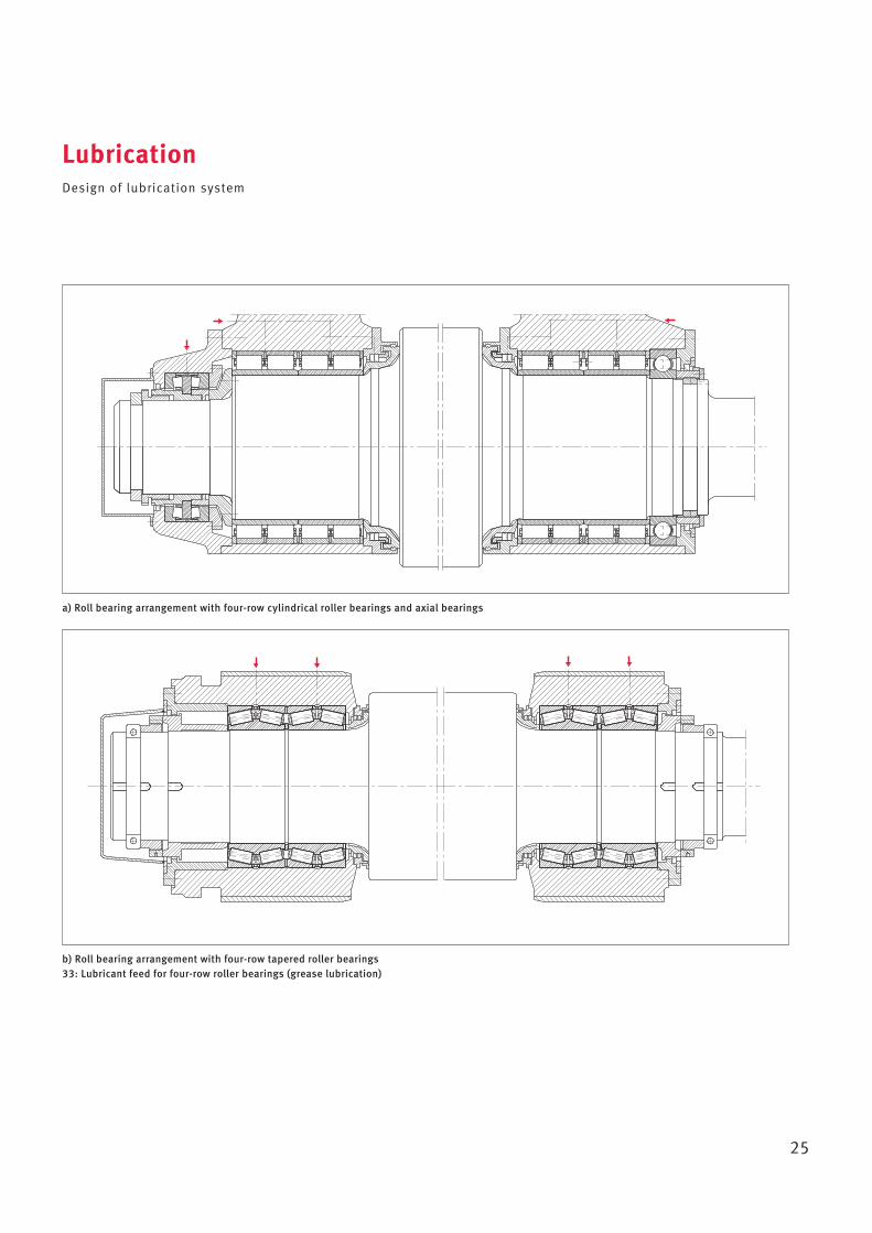
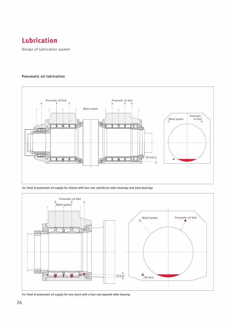
Oil injection lubrication, in whichthe lubricant is injected directlyinto the bearing under pressure via laterally arranged nozzles, is necessary in those cases whererecirculating oil lubrication doesnot give sufficient cooling. Oil injection lubrication permitsextremely high speeds. Recirculat-ing oil lubrication and oil injectionlubrication require some outlay oninlet and outlet pipes, pumps, oilcontainers, filters and if necessaryoil cooling systems. In the case of oil sump lubrication,the small lateral spaces in thechocks can provide the bearingswith only small quantities of oil.The oil is subjected to heavy stressand therefore undergoes rapidageing. Oil changes must thereforebe made frequently or syntheticoils with high resistance to ageingmay need to be used. In the case of pneumatic oil lubrication (minimal quantitylubrication), the oil is fed on acycle into the lubrication pipe of the bearing by a metering unitand then delivered to the bearingby an air stream. The oil is notatomised. As a result, it is possibleto use transmission oils of highviscosity with EP additives. The small quantity of oil suppliedis in addition to the oil sump thatis absolutely essential for bearinglubrication. This ensures thatlubrication occurs during start-upof the bearing and if there areshort disruptions to the oil feed.The position of oil outlet holes in the chock is defined for a horizontal shaft such that • for cylindrical roller bearings
the lowest rolling element isimmersed to 2/3 of its diameterin oil,
24
• for tapered roller bearings therolling element/guidance ribcontact is still immersed in oil.
The sealing effect is aided by thecontinuous overpressure thatbuilds up in the air stream in thehousing as well as the air flowingoutwards at the seals. The escap-ing oil still contains a small proportion of atomised oil which,on its escape, represents a certainenvironmental burden.
Design of lubrication system
Fill quantity with grease lubrication
The bearing arrangements shouldbe greased as follows:• Pack the bearings completely
with grease in order to ensurethat all functional surfaces arereliably supplied with grease.
• Fill any housing cavity adjacentto the bearing with grease onlyto the point where there is stillsufficient space for the grease inthe bearing. This prevents anexcessive quantity of grease circulating through the bearing.The free spaces adjacent to the bearing in the chocks are normally large enough to accom-modate the grease escaping fromthe bearing, so this grease fillingis not necessary if the bearingsrun at high speeds.
• In the case of bearings runningat very low speeds (n · dm < 50 000 min–1
· mm),pack the bearing and housingcompletely with grease. The working friction occurring isinsignificant.
Relubrication intervals with grease lubrication
The interval after which the greasein a bearing must be supplementedor renewed is dependent on thestress applied to the grease bybearing friction and on the oper -ating speed. The bearing friction isdetermined by the influences arising from load and from the different conditions of motion inthe individual bearing types. However it is also necessary, particularly for roll neck bearings,to take account of the environmen-tal conditions and the effectivenessof the sealing: If the sealing actionis inadequate, a drastic reductionin the relubrication interval maybe necessary due to the dampatmosphere, spray water androlling scale.Guidelines for relubrication can beobtained by checking the conditionof the grease and seals after cer-tain running times, ideally whenreplacing the roll, to determine inparticular whether contaminantshave been able to enter the bearing.
Lubricant feed
For effective lubrication, it is veryimportant that the grease or oil is fed in a targeted manner. The lubricant must be reliably supplied to the rolling and slidingsurfaces. When using grease lubrication, it must be ensuredthat excess grease can escape.
LubricationOil lubrication · Design of lubrication system
Overlubrication can causeincreased working action, leadingto increased heat generation. This may become so great that thegrease is damaged. Lubricant mustalso be specifically fed to theseals.
Grease lubrication
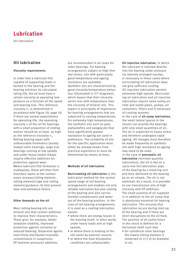
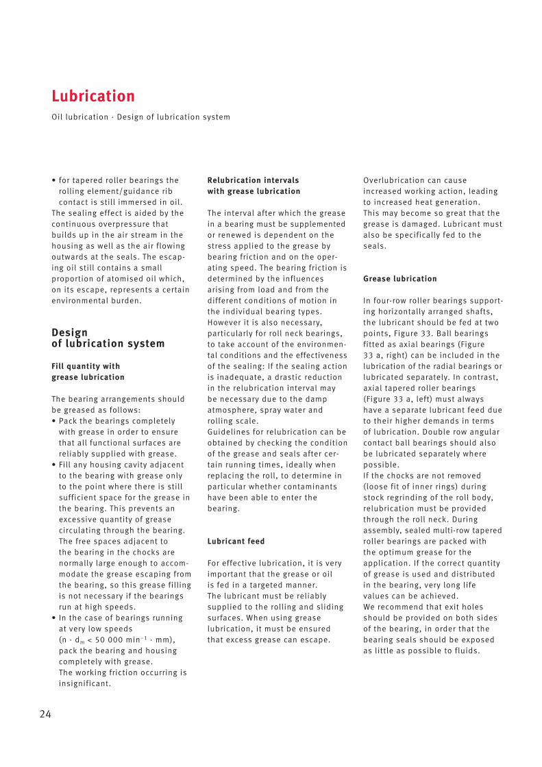
In four-row roller bearings support-ing horizontally arranged shafts,the lubricant should be fed at twopoints, Figure 33. Ball bearings fitted as axial bearings (Figure 33 a, right) can be included in thelubrication of the radial bearings orlubricated separately. In contrast,axial tapered roller bearings (Figure 33 a, left) must alwayshave a separate lubricant feed dueto their higher demands in termsof lubrication. Double row angularcontact ball bearings should alsobe lubricated separately wherepossible. If the chocks are not removed(loose fit of inner rings) duringstock regrinding of the roll body,relubrication must be providedthrough the roll neck. Duringassembly, sealed multi-row taperedroller bearings are packed with the optimum grease for the application. If the correct quantityof grease is used and distributedin the bearing, very long life values can be achieved. We recommend that exit holesshould be provided on both sidesof the bearing, in order that thebearing seals should be exposedas little as possible to fluids.
25
LubricationDesign of lubrication system
b) Roll bearing arrangement with four-row tapered roller bearings 33: Lubricant feed for four-row roller bearings (grease lubrication)
a) Roll bearing arrangement with four-row cylindrical roller bearings and axial bearings
26
Pneumatic oil lubrication
LubricationDesign of lubrication system
34: Feed of pneumatic oil supply for chocks with four-row cylindrical roller bearings and axial bearings
35: Feed of pneumatic oil supply for one chock with a four-row tapered roller bearing
Oil level
Bleed systemPneumatic
oil feed
Pneumatic oil feed
Bleed system
Pneumatic oil feed
Oil level
Bleed system Pneumatic oil feed
Oil level
Pneumatic oil feed
Bleed system
27
LubricationDesign of lubrication system
Recirculating oil lubrication
36: Oil feed and oil outlet in recirculating lubrication
28
Tolerances of roll neck bearings
Tolerances of roll neck bearings
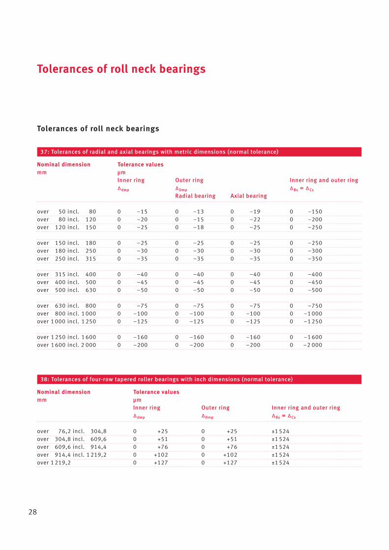
37: Tolerances of radial and axial bearings with metric dimensions (normal tolerance)
Nominal dimension Tolerance valuesmm µm
Inner ring Outer ring Inner ring and outer ring∆dmp ∆Dmp ∆Bs = ∆Cs
Radial bearing Axial bearing
over 50 incl. 80 0 –15 0 –13 0 –19 0 –150over 80 incl. 120 0 –20 0 –15 0 –22 0 –200over 120 incl. 150 0 –25 0 –18 0 –25 0 –250
over 150 incl. 180 0 –25 0 –25 0 –25 0 –250over 180 incl. 250 0 –30 0 –30 0 –30 0 –300over 250 incl. 315 0 –35 0 –35 0 –35 0 –350
over 315 incl. 400 0 –40 0 –40 0 –40 0 –400over 400 incl. 500 0 –45 0 –45 0 –45 0 –450over 500 incl. 630 0 –50 0 –50 0 –50 0 –500
over 630 incl. 800 0 –75 0 –75 0 –75 0 –750over 800 incl. 1 000 0 –100 0 –100 0 –100 0 –1 000over 1 000 incl. 1 250 0 –125 0 –125 0 –125 0 –1 250
over 1 250 incl. 1 600 0 –160 0 –160 0 –160 0 –1 600over 1 600 incl. 2 000 0 –200 0 –200 0 –200 0 –2 000
38: Tolerances of four-row tapered roller bearings with inch dimensions (normal tolerance)
Nominal dimension Tolerance valuesmm µm
Inner ring Outer ring Inner ring and outer ring∆dmp ∆Dmp ∆Bs = ∆Cs
over 76,2 incl. 304,8 0 +25 0 +25 ±1 524over 304,8 incl. 609,6 0 +51 0 +51 ±1 524over 609,6 incl. 914,4 0 +76 0 +76 ±1 524over 914,4 incl. 1 219,2 0 +102 0 +102 ±1 524over 1 219,2 0 +127 0 +127 ±1 524
29
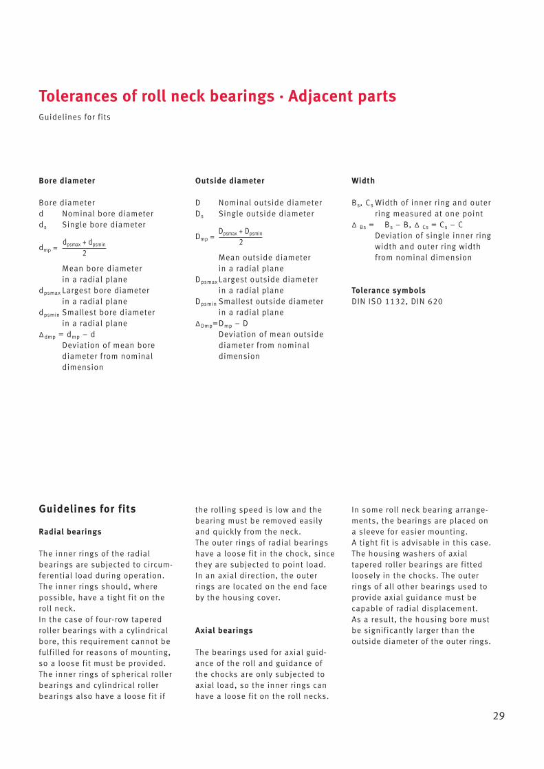
Bore diameter
Bore diameterd Nominal bore diameterds Single bore diameter
Mean bore diameter in a radial plane
dpsmax Largest bore diameter in a radial plane
dpsmin Smallest bore diameter in a radial plane
∆dmp = dmp – dDeviation of mean bore diameter from nominaldimension
Outside diameter
D Nominal outside diameterDs Single outside diameter
Mean outside diameter in a radial plane
Dpsmax Largest outside diameter in a radial plane
Dpsmin Smallest outside diameter in a radial plane
∆Dmp=Dmp – DDeviation of mean outsidediameter from nominaldimension
Tolerances of roll neck bearings · Adjacent partsGuidelines for fits
Width
Bs, Cs Width of inner ring and outerring measured at one point
∆ Bs = Bs – B, ∆ Cs = Cs – CDeviation of single inner ringwidth and outer ring widthfrom nominal dimension
Tolerance symbolsDIN ISO 1132, DIN 620
dmp =dpsmax + dpsmin
2
Dmp =Dpsmax + Dpsmin
2
Guidelines for fits
Radial bearings
The inner rings of the radial bearings are subjected to circum-ferential load during operation.The inner rings should, where possible, have a tight fit on theroll neck.In the case of four-row taperedroller bearings with a cylindricalbore, this requirement cannot befulfilled for reasons of mounting,so a loose fit must be provided.The inner rings of spherical rollerbearings and cylindrical rollerbearings also have a loose fit if
the rolling speed is low and thebearing must be removed easilyand quickly from the neck. The outer rings of radial bearingshave a loose fit in the chock, sincethey are subjected to point load.In an axial direction, the outerrings are located on the end faceby the housing cover.
Axial bearings
The bearings used for axial guid-ance of the roll and guidance ofthe chocks are only subjected toaxial load, so the inner rings canhave a loose fit on the roll necks.
In some roll neck bearing arrange-ments, the bearings are placed ona sleeve for easier mounting. A tight fit is advisable in this case.The housing washers of axialtapered roller bearings are fittedloosely in the chocks. The outerrings of all other bearings used toprovide axial guidance must becapable of radial displacement. As a result, the housing bore mustbe significantly larger than theoutside diameter of the outer rings.

30
Adjacent partsGuidelines for fits
39: Tolerance zones for roll necks and sleeves (for bearing tolerances see page 28)
d d1d d1
d d d
d d
d d
d d d
d d
d1d d1d
ddd
Nominal dimension Tolerance1)
mm mm
d < 170 p6d = 170...210 r6d > 210...225 +0,100...+0,130
> 225...250 +0,110...+0,140> 250...280 +0,125...+0,160> 280...315 +0,140...+0,170> 315...355 +0,155...+0,190> 355...400 +0,170...+0,210> 400...450 +0,195...+0,230> 450 s6
d e7
d < 315 –0,180...–0,230d = 315...630 –0,240...–0,300
> 630...800 –0,325...–0,410> 800 –0,350...–0,450
d = 101,6...127,0 –0,100...–0,125> 127,0...152,4 –0,130...–0,155> 152,4...203,2 –0,150...–0,175> 203,2...304,8 –0,180...–0,205> 304,8...609,6 –0,200...–0,249> 609,6...914,4 –0,250...–0,334> 914,4 –0,300...–0,400
d e7
d k6
d1 e9/H7
d e7
d k6
d1 e9/H7
1) In the case of high speeds and bearings with a tapered bore, please contact us to discuss the tolerances for the adjacent parts.
Cylindrical roller bearingsand spherical roller bearings with tight fit
Cylindrical roller bearingsand spherical roller bearings with loose fit
Tapered roller bearings,metric tolerances, with loose fit
Angular contact ball bearings and deep grooveball bearings mounted onroll neck
Tapered roller bearings, inch tolerances, with loose fit
Axial tapered roller bearings,double row tapered rollerbearings (axial bearings), axial spherical roller bear-ings mounted on roll neck
Angular contact ball bearings and deep grooveball bearings mounted onsleeve
Axial tapered roller bearings,axial spherical roller bearings mounted on sleeve
D D D D
Adjacent partsGuidelines for fits
31
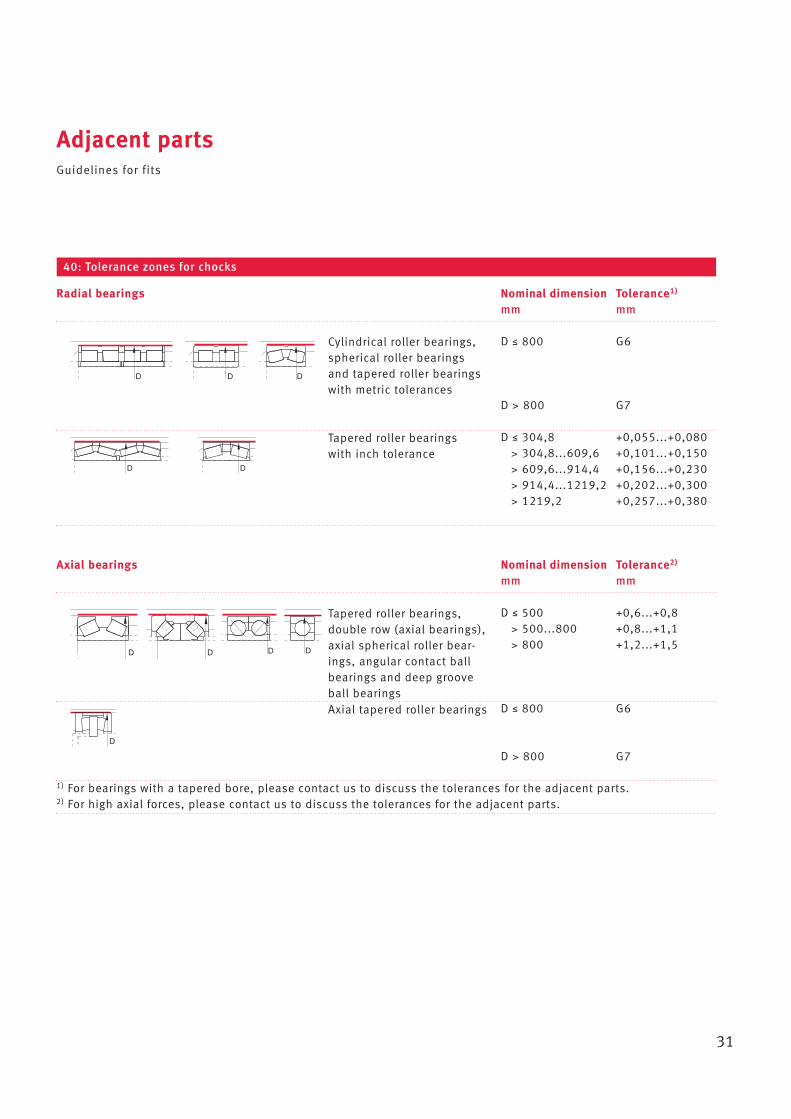
40: Tolerance zones for chocks
D D D
DD
D
Axial bearings Nominal dimension Tolerance2)
mm mm
D ≤ 500 +0,6...+0,8> 500...800 +0,8...+1,1> 800 +1,2...+1,5
D ≤ 800 G6
D > 800 G7
1) For bearings with a tapered bore, please contact us to discuss the tolerances for the adjacent parts.2) For high axial forces, please contact us to discuss the tolerances for the adjacent parts.
Cylindrical roller bearings,spherical roller bearingsand tapered roller bearingswith metric tolerances
Tapered roller bearings,double row (axial bearings),axial spherical roller bear-ings, angular contact ballbearings and deep grooveball bearings
Tapered roller bearings with inch tolerance
Axial tapered roller bearings
Radial bearings Nominal dimension Tolerance1)
mm mm
D ≤ 800 G6
D > 800 G7
D ≤ 304,8 +0,055...+0,080> 304,8...609,6 +0,101...+0,150> 609,6...914,4 +0,156...+0,230> 914,4...1219,2 +0,202...+0,300> 1219,2 +0,257...+0,380
32
Adjacent partsTolerances for cylindrical bearing seats
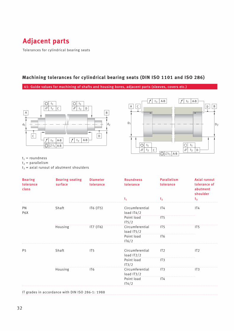
Machining tolerances for cylindrical bearing seats (DIN ISO 1101 and ISO 286)
t1 t2 t3
PN Shaft IT6 (IT5) Circumferential IT4 IT4P6X load IT4/2
Point load IT5IT5/2
Housing IT7 (IT6) Circumferential IT5 IT5load IT5/2Point load IT6IT6/2
P5 Shaft IT5 Circumferential IT2 IT2load IT2/2Point load IT3IT3/2
Housing IT6 Circumferential IT3 IT3load IT3/2Point load IT4IT4/2
IT grades in accordance with DIN ISO 286-1: 1988
d1 d2D1 D2
CA
A-B
D B
t3 A-Bt3
A
t1
2t C D
t1
2t
B
DA-Bt3t3
CA-B
A-Bt1
D2t
t1
C
t1
2tA-Bt1
t1 = roundnesst2 = parallelismt3 = axial runout of abutment shoulders
Roundness tolerance
Axial runouttolerance ofabutmentshoulder
Parallelism tolerance
Diameter tolerance
Bearing seatingsurface
Bearingtoleranceclass
41: Guide values for machining of shafts and housing bores, adjacent parts (sleeves, covers etc.)
Adjacent partsRoughness of bearing seats
33
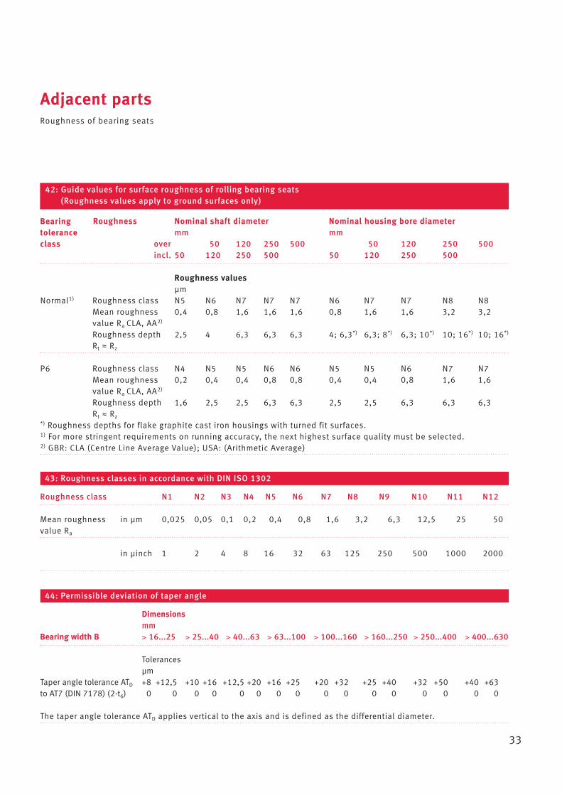
Nominal shaft diameter Nominal housing bore diametermm mm
over 50 120 250 500 50 120 250 500incl. 50 120 250 500 50 120 250 500
Roughness valuesµm
Normal1) Roughness class N5 N6 N7 N7 N7 N6 N7 N7 N8 N8Mean roughness 0,4 0,8 1,6 1,6 1,6 0,8 1,6 1,6 3,2 3,2value Ra CLA, AA2)
Roughness depth 2,5 4 6,3 6,3 6,3 4; 6,3*) 6,3; 8*) 6,3; 10*) 10; 16*) 10; 16*)
Rt ≈ Rz
P6 Roughness class N4 N5 N5 N6 N6 N5 N5 N6 N7 N7Mean roughness 0,2 0,4 0,4 0,8 0,8 0,4 0,4 0,8 1,6 1,6value Ra CLA, AA2)
Roughness depth 1,6 2,5 2,5 6,3 6,3 2,5 2,5 6,3 6,3 6,3Rt ≈ Rz
*) Roughness depths for flake graphite cast iron housings with turned fit surfaces.1) For more stringent requirements on running accuracy, the next highest surface quality must be selected.2) GBR: CLA (Centre Line Average Value); USA: (Arithmetic Average)
42: Guide values for surface roughness of rolling bearing seats (Roughness values apply to ground surfaces only)
43: Roughness classes in accordance with DIN ISO 1302
Roughness class N1 N2 N3 N4 N5 N6 N7 N8 N9 N10 N11 N12
Mean roughness in µm 0,025 0,05 0,1 0,2 0,4 0,8 1,6 3,2 6,3 12,5 25 50value Ra
in µinch 1 2 4 8 16 32 63 125 250 500 1000 2000
44: Permissible deviation of taper angle
Dimensionsmm
Bearing width B > 16...25 > 25...40 > 40...63 > 63...100 > 100...160 > 160...250 > 250...400 > 400...630
Tolerancesµm
Taper angle tolerance ATD +8 +12,5 +10 +16 +12,5 +20 +16 +25 +20 +32 +25 +40 +32 +50 +40 +63to AT7 (DIN 7178) (2·t6) 0 0 0 0 0 0 0 0 0 0 0 0 0 0 0 0
The taper angle tolerance ATD applies vertical to the axis and is defined as the differential diameter.
Bearingtoleranceclass
Roughness
Adjacent partsTolerances for roll necks and chocks
34
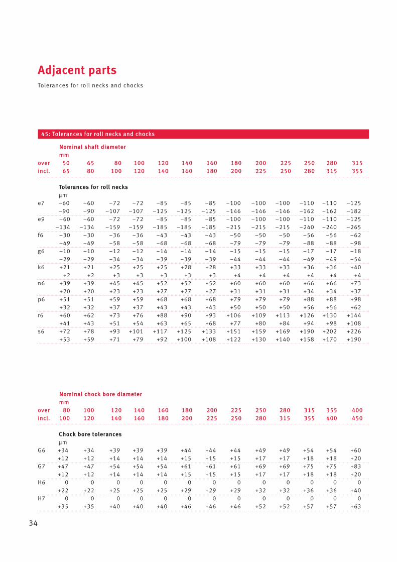
45: Tolerances for roll necks and chocks
Nominal shaft diametermm
over 50 65 80 100 120 140 160 180 200 225 250 280 315incl. 65 80 100 120 140 160 180 200 225 250 280 315 355
Tolerances for roll necksµm
e7 –60 –60 –72 –72 –85 –85 –85 –100 –100 –100 –110 –110 –125–90 –90 –107 –107 –125 –125 –125 –146 –146 –146 –162 –162 –182
e9 –60 –60 –72 –72 –85 –85 –85 –100 –100 –100 –110 –110 –125–134 –134 –159 –159 –185 –185 –185 –215 –215 –215 –240 –240 –265
f6 –30 –30 –36 –36 –43 –43 –43 –50 –50 –50 –56 –56 –62–49 –49 –58 –58 –68 –68 –68 –79 –79 –79 –88 –88 –98
g6 –10 –10 –12 –12 –14 –14 –14 –15 –15 –15 –17 –17 –18–29 –29 –34 –34 –39 –39 –39 –44 –44 –44 –49 –49 –54
k6 +21 +21 +25 +25 +25 +28 +28 +33 +33 +33 +36 +36 +40+2 +2 +3 +3 +3 +3 +3 +4 +4 +4 +4 +4 +4
n6 +39 +39 +45 +45 +52 +52 +52 +60 +60 +60 +66 +66 +73+20 +20 +23 +23 +27 +27 +27 +31 +31 +31 +34 +34 +37
p6 +51 +51 +59 +59 +68 +68 +68 +79 +79 +79 +88 +88 +98+32 +32 +37 +37 +43 +43 +43 +50 +50 +50 +56 +56 +62
r6 +60 +62 +73 +76 +88 +90 +93 +106 +109 +113 +126 +130 +144+41 +43 +51 +54 +63 +65 +68 +77 +80 +84 +94 +98 +108
s6 +72 +78 +93 +101 +117 +125 +133 +151 +159 +169 +190 +202 +226+53 +59 +71 +79 +92 +100 +108 +122 +130 +140 +158 +170 +190
Nominal chock bore diametermm
over 80 100 120 140 160 180 200 225 250 280 315 355 400incl. 100 120 140 160 180 200 225 250 280 315 355 400 450
Chock bore tolerancesµm
G6 +34 +34 +39 +39 +39 +44 +44 +44 +49 +49 +54 +54 +60+12 +12 +14 +14 +14 +15 +15 +15 +17 +17 +18 +18 +20
G7 +47 +47 +54 +54 +54 +61 +61 +61 +69 +69 +75 +75 +83+12 +12 +14 +14 +14 +15 +15 +15 +17 +17 +18 +18 +20
H6 0 0 0 0 0 0 0 0 0 0 0 0 0+22 +22 +25 +25 +25 +29 +29 +29 +32 +32 +36 +36 +40
H7 0 0 0 0 0 0 0 0 0 0 0 0 0+35 +35 +40 +40 +40 +46 +46 +46 +52 +52 +57 +57 +63
Adjacent partsTolerances for roll necks and chocks
35
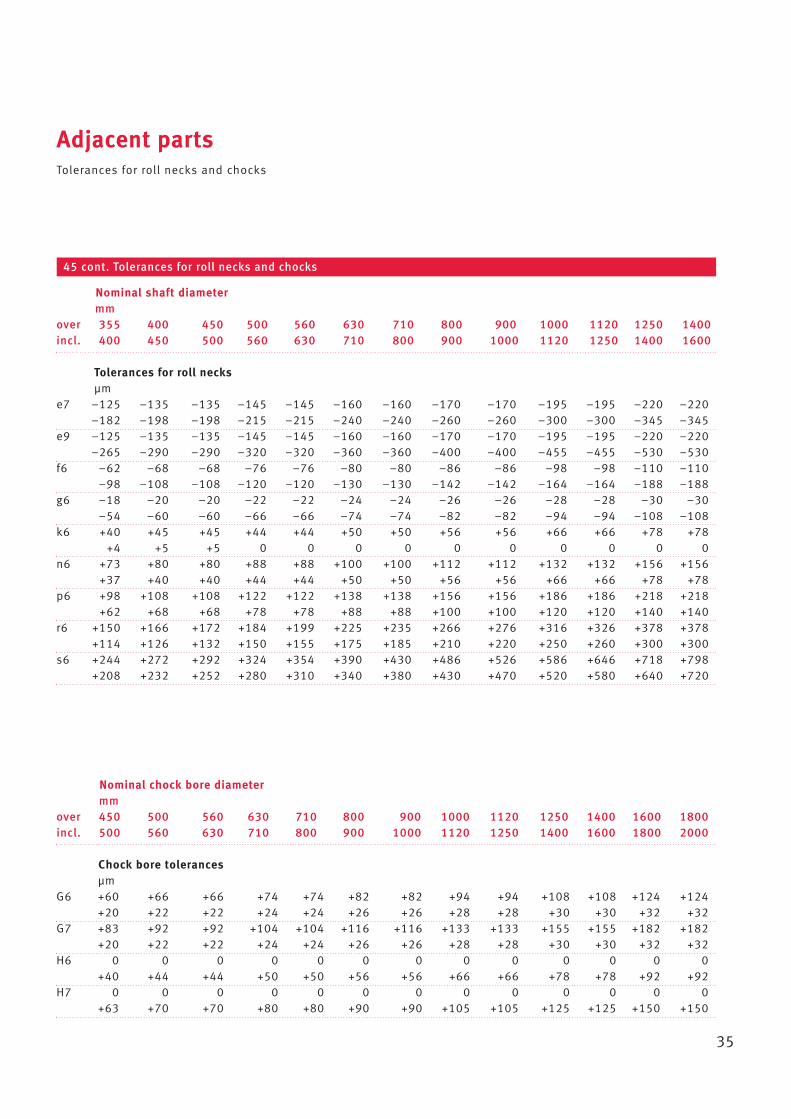
45 cont. Tolerances for roll necks and chocks
Nominal shaft diametermm
over 355 400 450 500 560 630 710 800 900 1000 1120 1250 1400incl. 400 450 500 560 630 710 800 900 1000 1120 1250 1400 1600
Tolerances for roll necksµm
e7 –125 –135 –135 –145 –145 –160 –160 –170 –170 –195 –195 –220 –220–182 –198 –198 –215 –215 –240 –240 –260 –260 –300 –300 –345 –345
e9 –125 –135 –135 –145 –145 –160 –160 –170 –170 –195 –195 –220 –220–265 –290 –290 –320 –320 –360 –360 –400 –400 –455 –455 –530 –530
f6 –62 –68 –68 –76 –76 –80 –80 –86 –86 –98 –98 –110 –110–98 –108 –108 –120 –120 –130 –130 –142 –142 –164 –164 –188 –188
g6 –18 –20 –20 –22 –22 –24 –24 –26 –26 –28 –28 –30 –30–54 –60 –60 –66 –66 –74 –74 –82 –82 –94 –94 –108 –108
k6 +40 +45 +45 +44 +44 +50 +50 +56 +56 +66 +66 +78 +78+4 +5 +5 0 0 0 0 0 0 0 0 0 0
n6 +73 +80 +80 +88 +88 +100 +100 +112 +112 +132 +132 +156 +156+37 +40 +40 +44 +44 +50 +50 +56 +56 +66 +66 +78 +78
p6 +98 +108 +108 +122 +122 +138 +138 +156 +156 +186 +186 +218 +218+62 +68 +68 +78 +78 +88 +88 +100 +100 +120 +120 +140 +140
r6 +150 +166 +172 +184 +199 +225 +235 +266 +276 +316 +326 +378 +378+114 +126 +132 +150 +155 +175 +185 +210 +220 +250 +260 +300 +300
s6 +244 +272 +292 +324 +354 +390 +430 +486 +526 +586 +646 +718 +798+208 +232 +252 +280 +310 +340 +380 +430 +470 +520 +580 +640 +720
Nominal chock bore diametermm
over 450 500 560 630 710 800 900 1000 1120 1250 1400 1600 1800incl. 500 560 630 710 800 900 1000 1120 1250 1400 1600 1800 2000
Chock bore tolerancesµm
G6 +60 +66 +66 +74 +74 +82 +82 +94 +94 +108 +108 +124 +124+20 +22 +22 +24 +24 +26 +26 +28 +28 +30 +30 +32 +32
G7 +83 +92 +92 +104 +104 +116 +116 +133 +133 +155 +155 +182 +182+20 +22 +22 +24 +24 +26 +26 +28 +28 +30 +30 +32 +32
H6 0 0 0 0 0 0 0 0 0 0 0 0 0+40 +44 +44 +50 +50 +56 +56 +66 +66 +78 +78 +92 +92
H7 0 0 0 0 0 0 0 0 0 0 0 0 0+63 +70 +70 +80 +80 +90 +90 +105 +105 +125 +125 +150 +150
Conditions for inner ringswith loose fits
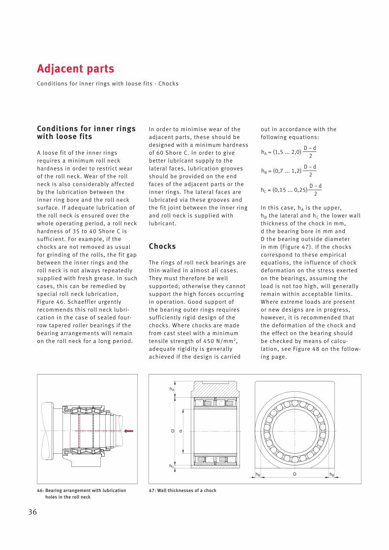
A loose fit of the inner ringsrequires a minimum roll neck hardness in order to restrict wearof the roll neck. Wear of the rollneck is also considerably affectedby the lubrication between theinner ring bore and the roll necksurface. If adequate lubrication ofthe roll neck is ensured over thewhole operating period, a roll neckhardness of 35 to 40 Shore C issufficient. For example, if thechocks are not removed as usualfor grinding of the rolls, the fit gapbetween the inner rings and theroll neck is not always repeatedlysupplied with fresh grease. In suchcases, this can be remedied byspecial roll neck lubrication, Figure 46. Schaeffler urgently recommends this roll neck lubri - cation in the case of sealed four-row tapered roller bearings if the bearing arrangements will remainon the roll neck for a long period.
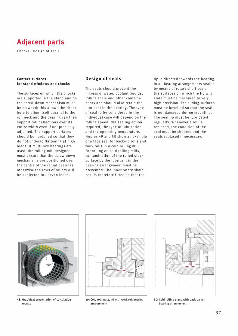
In order to minimise wear of theadjacent parts, these should bedesigned with a minimum hardnessof 60 Shore C. In order to give better lubricant supply to the lateral faces, lubrication groovesshould be provided on the endfaces of the adjacent parts or theinner rings. The lateral faces arelubricated via these grooves andthe fit joint between the inner ringand roll neck is supplied withlubricant.
Chocks
The rings of roll neck bearings arethin-walled in almost all cases.They must therefore be well supported; otherwise they cannotsupport the high forces occurringin operation. Good support of the bearing outer rings requiressufficiently rigid design of thechocks. Where chocks are madefrom cast steel with a minimumtensile strength of 450 N/mm2,adequate rigidity is generallyachieved if the design is carried
Adjacent partsConditions for inner rings with loose fits · Chocks
36
46: Bearing arrangement with lubricationholes in the roll neck
47: Wall thicknesses of a chock
D d
D
hA
hC
hB hB
out in accordance with the following equations:
In this case, hA is the upper, hB the lateral and hC the lower wall thickness of the chock in mm, d the bearing bore in mm and D the bearing outside diameter in mm (Figure 47). If the chockscorrespond to these empiricalequations, the influence of chockdeformation on the stress exertedon the bearings, assuming theload is not too high, will generallyremain within acceptable limits.Where extreme loads are presentor new designs are in progress,however, it is recommended thatthe deformation of the chock andthe effect on the bearing shouldbe checked by means of calcu -lation, see Figure 48 on the follow-ing page.
hA = (1,5 ... 2,0)D } d
2
hB = (0,7 ... 1,2)D } d
2
hC = (0,15 ... 0,25)D } d
2
Contact surfaces for stand windows and chocks
The surfaces on which the chocksare supported in the stand and onthe screw-down mechanism mustbe crowned; this allows the chockbore to align itself parallel to theroll neck and the bearing can thensupport roll deflections over itsentire width even if not preciselyadjusted. The support surfacesshould be hardened so that theydo not undergo flattening at highloads. If multi-row bearings areused, the rolling mill designermust ensure that the screw-downmechanisms are positioned overthe centre of the radial bearings,otherwise the rows of rollers willbe subjected to uneven loads.
Design of seals
The seals should prevent theingress of water, coolant liquids,rolling scale and other contami-nants and should also retain thelubricant in the bearing. The typeof seal to be considered in theindividual case will depend on therolling speed, the sealing actionrequired, the type of lubricationand the operating temperature.Figures 49 and 50 show an exampleof a face seal for back-up rolls andwork rolls in a cold rolling mill.For rolling on cold rolling mills,contamination of the rolled stocksurface by the lubricant in thebearing arrangement must be prevented. The inner rotary shaftseal is therefore fitted so that the
Adjacent partsChocks · Design of seals
37
lip is directed towards the bearing.In all bearing arrangements sealedby means of rotary shaft seals, the surfaces on which the lip willslide must be machined to veryhigh precision. The sliding surfacesmust be bevelled so that the sealis not damaged during mounting.The seal lip must be lubricatedregularly. Whenever a roll isreplaced, the condition of the seal must be checked and theseals replaced if necessary.
48: Graphical presentation of calculationresults
49: Cold rolling stand with work roll bearingarrangement
50: Cold rolling stand with back-up roll bearing arrangement
Mounting and maintenancePreparations for mounting
38
General guidelines for mountingand dismounting can be found inthe Mounting Handbook MH1. In addition, some important workprocesses in the operation ofrolling mills are covered in furtherdetail on the following pages.
Preparations for mounting
Before mounting of the bearings is started, the mating parts andadjacent parts, in other words rollnecks, chocks, sleeves, covers etc.must be checked for dimensionalaccuracy and geometrical accuracywith reference to the design drawing.The specified surface quality ofthe roll seats, chocks and lateralcontact parts must be inspected.All burrs and sharp edges resultingfrom machining must be broken or rounded.
51: Measurement points for inspection of roll necks
123 4
a1 b1 d1 e1c1 f1 f2 d2e2 c2 a2b2
52: Measurement points for inspection of chocks
123
4
a b c d
A1 A2
A
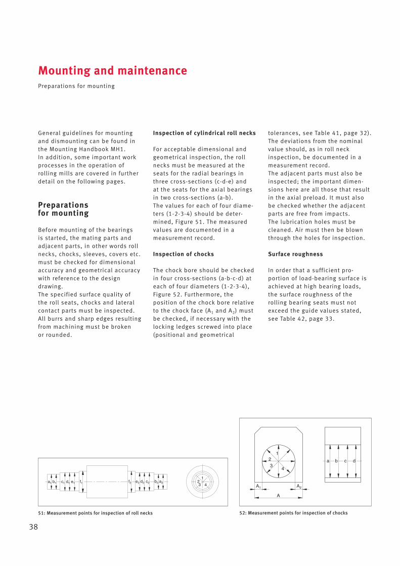
Inspection of cylindrical roll necks
For acceptable dimensional andgeometrical inspection, the rollnecks must be measured at theseats for the radial bearings inthree cross-sections (c-d-e) and at the seats for the axial bearingsin two cross-sections (a-b). The values for each of four diame-ters (1-2-3-4) should be deter-mined, Figure 51. The measuredvalues are documented in a measurement record.
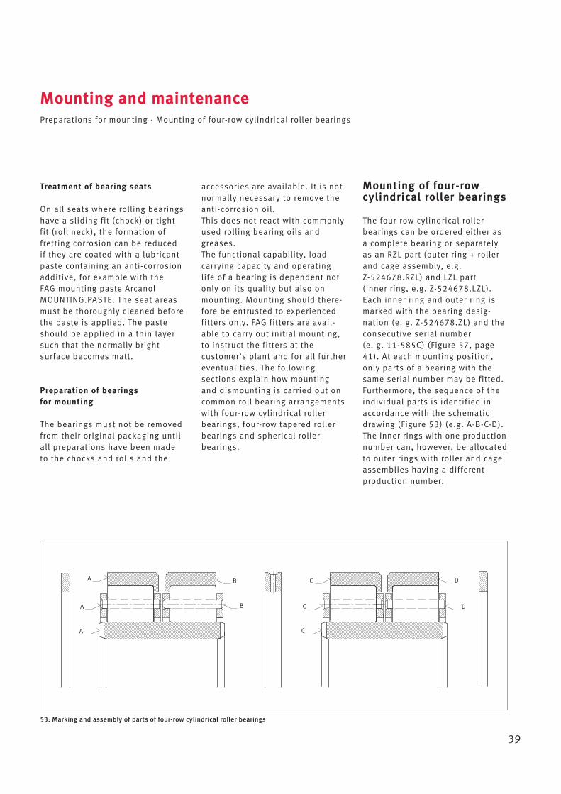
Inspection of chocks
The chock bore should be checkedin four cross-sections (a-b-c-d) ateach of four diameters (1-2-3-4),Figure 52. Furthermore, the position of the chock bore relativeto the chock face (A1 and A2) mustbe checked, if necessary with thelocking ledges screwed into place(positional and geo metrical
tolerances, see Table 41, page 32).The deviations from the nominalvalue should, as in roll neckinspection, be documented in ameasurement record. The adjacent parts must also beinspected; the important dimen-sions here are all those that resultin the axial preload. It must alsobe checked whether the adjacentparts are free from impacts. The lubrication holes must becleaned. Air must then be blownthrough the holes for inspection.
Surface roughness
In order that a sufficient pro -portion of load-bearing surface isachieved at high bearing loads,the surface roughness of therolling bearing seats must notexceed the guide values stated,see Table 42, page 33.
39
Treatment of bearing seats
On all seats where rolling bearingshave a sliding fit (chock) or tightfit (roll neck), the formation offretting corrosion can be reducedif they are coated with a lubricantpaste containing an anti-corrosionadditive, for example with the FAG mounting paste ArcanolMOUNTING.PASTE. The seat areasmust be thoroughly cleaned beforethe paste is applied. The pasteshould be applied in a thin layersuch that the normally bright surface becomes matt.
Preparation of bearings for mounting
The bearings must not be removedfrom their original packaging untilall preparations have been madeto the chocks and rolls and the
accessories are available. It is notnormally necessary to remove theanti-corrosion oil. This does not react with commonlyused rolling bearing oils andgreases. The functional capability, load carrying capacity and operatinglife of a bearing is dependent notonly on its quality but also onmounting. Mounting should there-fore be entrusted to experiencedfitters only. FAG fitters are avail-able to carry out initial mounting,to instruct the fitters at the customer’s plant and for all furthereventualities. The following sections explain how mountingand dismounting is carried out oncommon roll bearing arrangementswith four-row cylindrical rollerbearings, four-row tapered rollerbearings and spherical roller bearings.
Mounting and maintenancePreparations for mounting · Mounting of four-row cylindrical roller bearings
Mounting of four-rowcylindrical roller bearings
The four-row cylindrical roller bearings can be ordered either asa complete bearing or separatelyas an RZL part (outer ring + rollerand cage assembly, e.g. Z-524678.RZL) and LZL part (inner ring, e.g. Z-524678.LZL).Each inner ring and outer ring ismarked with the bearing desig -nation (e. g. Z-524678.ZL) and theconsecutive serial number (e. g. 11-585C) (Figure 57, page41). At each mounting position,only parts of a bearing with thesame serial number may be fitted.Furthermore, the sequence of theindividual parts is identified inaccordance with the schematicdrawing (Figure 53) (e.g. A-B-C-D).The inner rings with one productionnumber can, however, be allocatedto outer rings with roller and cageassemblies having a different production number.
53: Marking and assembly of parts of four-row cylindrical roller bearings
A
A
A
B
B
C
C
C
D
D
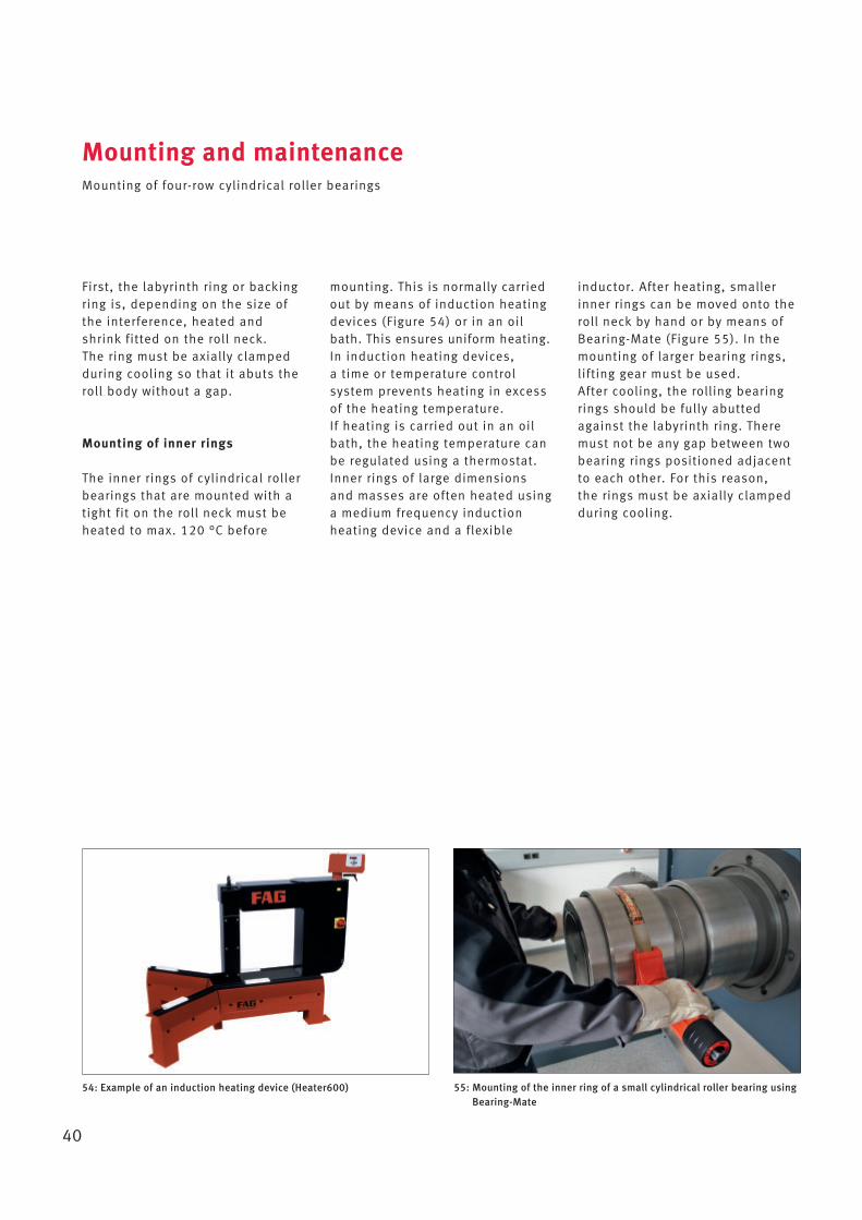
First, the labyrinth ring or backingring is, depending on the size ofthe interference, heated andshrink fitted on the roll neck. The ring must be axially clampedduring cooling so that it abuts theroll body without a gap.
Mounting of inner rings
The inner rings of cylindrical rollerbearings that are mounted with atight fit on the roll neck must beheated to max. 120 °C before
mounting. This is normally carriedout by means of induction heatingdevices (Figure 54) or in an oilbath. This ensures uniform heating.In induction heating devices, a time or temperature control system prevents heating in excessof the heating temperature. If heating is carried out in an oilbath, the heating temperature canbe regulated using a thermostat.Inner rings of large dimensionsand masses are often heated usinga medium frequency inductionheating device and a flexible
Mounting and maintenanceMounting of four-row cylindrical roller bearings
40
inductor. After heating, smallerinner rings can be moved onto theroll neck by hand or by means ofBearing-Mate (Figure 55). In themounting of larger bearing rings,lifting gear must be used.After cooling, the rolling bearingrings should be fully abuttedagainst the labyrinth ring. Theremust not be any gap between twobearing rings positioned adjacentto each other. For this reason, the rings must be axially clamped during cooling.
54: Example of an induction heating device (Heater600) 55: Mounting of the inner ring of a small cylindrical roller bearing usingBearing-Mate

Mounting of outer rings
The outer rings of cylindrical rollerbearings have a sliding fit in thechocks. Smaller outer rings can bemoved into the chock by hand.The outer rings or cages of largerbearings can be lifted into thechock, for example with the aid of a crane, Figure 56.On the end faces of the outerrings, four zones with the numbersI, II, III and IV are marked, Figure57. At first mounting, the outerrings are positioned such that the load acts on the load zone I.The load zones should be positioned in the same directionon all outer rings.We recommend that the bearingsshould be thoroughly checkedafter a running time of 1 000 to 1 200 hours and the load zones ofthe outer rings changed. At thefirst load zone change, the outerrings in the chock must be rotatedby 180° in load zone III and in allfurther changes in load zone II andIV respectively.
Mounting and maintenanceMounting of four-row cylindrical roller bearings
41
56: Mounting of a cylindrical roller outer ring using a crane
57: Marking of a four-row cylindrical roller bearing
IV
FAG
Z-S
17684.01.ZL I
F II 10-18 A III
FA
G
Z
-S17
684.01.ZL F
0-18 A
Load zone marking
Serial number
“COUN“
“COUN
“
TRY
TRY
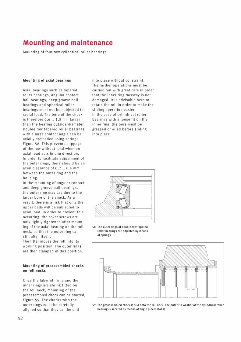
Mounting of axial bearings
Axial bearings such as taperedroller bearings, angular contactball bearings, deep groove ballbearings and spherical roller bearings must not be subjected toradial load. The bore of the chockis therefore 0,6 … 1,5 mm largerthan the bearing outside diameter.Double row tapered roller bearingswith a large contact angle can beaxially preloaded using springs,Figure 58. This prevents slippageof the row without load when anaxial load acts in one direction. In order to facilitate adjustment ofthe outer rings, there should be anaxial clearance of 0,2 … 0,4 mmbetween the outer ring and thehousing.In the mounting of angular contactand deep groove ball bearings, the outer ring may sag due to thelarger bore of the chock. As aresult, there is a risk that only theupper balls will be subjected toaxial load. In order to prevent thisoccurring, the cover screws areonly lightly tightened after mount-ing of the axial bearing on the rollneck, so that the outer ring canstill align itself.The fitter moves the roll into itsworking position. The outer ringsare then clamped in this position.
Mounting of preassembled chockson roll necks
Once the labyrinth ring and theinner rings are shrink fitted on the roll neck, mounting of the preassembled chock can be started,Figure 59. The chocks with the outer rings must be carefullyaligned so that they can be slid
Mounting and maintenanceMounting of four-row cylindrical roller bearings
42
58: The outer rings of double row taperedroller bearings are adjusted by means of springs
59: The preassembled chock is slid onto the roll neck. The outer rib washer of the cylindrical rollerbearing is secured by means of angle pieces (tabs)
into place without constraint.The further operations must becarried out with great care in orderthat the inner ring raceway is notdamaged. It is advisable here torotate the roll in order to make thesliding operation easier.In the case of cylindrical rollerbearings with a loose fit on theinner ring, the bore must begreased or oiled before slidinginto place.
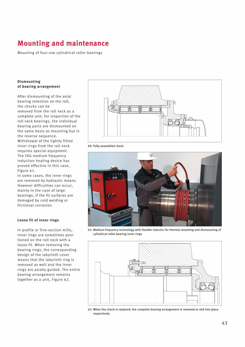
Dismounting of bearing arrangement
After dismounting of the axialbearing retention on the roll, the chocks can beremoved from the roll neck as acomplete unit. For inspection of theroll neck bearings, the individualbearing parts are dismounted onthe same basis as mounting but inthe reverse sequence.Withdrawal of the tightly fittedinner rings from the roll neckrequires special equipment. The FAG medium frequency induction heating device hasproved effective in this case, Figure 61. In some cases, the inner rings are removed by hydraulic means. However difficulties can occur,mainly in the case of large bearings, if the fit surfaces aredamaged by cold welding or frictional corrosion.
Loose fit of inner rings
In profile or fine-section mills,inner rings are sometimes posi-tioned on the roll neck with aloose fit. When removing the bearing rings, the correspondingdesign of the labyrinth covermeans that the labyrinth ring isremoved as well and the innerrings are axially guided. The entirebearing arrangement remainstogether as a unit, Figure 62.
Mounting and maintenanceMounting of four-row cylindrical roller bearings
43
60: Fully assembled chock
62: When the chock is replaced, the complete bearing arrangement is removed or slid into placerespectively
61: Medium frequency technology with flexible inductor for thermal mounting and dismounting ofcylindrical roller bearing inner rings
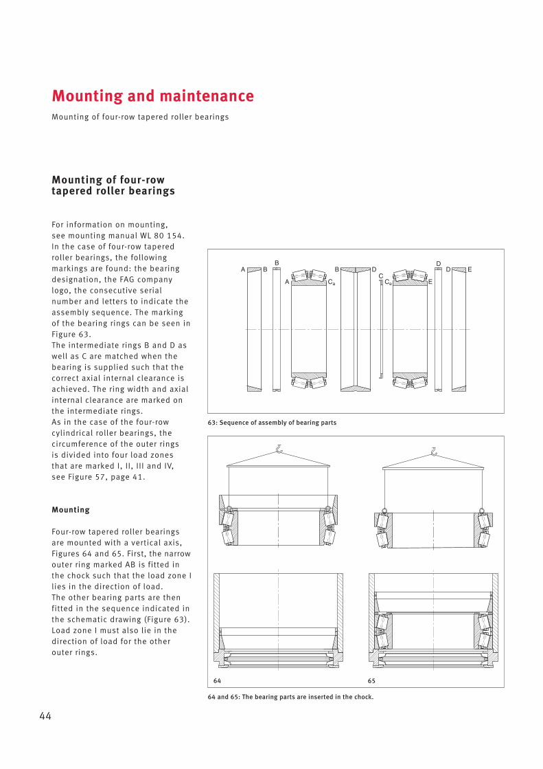
Mounting of four-rowtapered roller bearings
For information on mounting, see mounting manual WL 80 154.In the case of four-row taperedroller bearings, the following markings are found: the bearingdesignation, the FAG companylogo, the consecutive serial number and letters to indicate theassembly sequence. The markingof the bearing rings can be seen inFigure 63.The intermediate rings B and D aswell as C are matched when thebearing is supplied such that thecorrect axial internal clearance isachieved. The ring width and axialinternal clearance are marked onthe intermediate rings.As in the case of the four-rowcylindrical roller bearings, the circumference of the outer rings is divided into four load zones that are marked I, II, III and IV, see Figure 57, page 41.
Mounting
Four-row tapered roller bearingsare mounted with a vertical axis,Figures 64 and 65. First, the narrowouter ring marked AB is fitted inthe chock such that the load zone Ilies in the direction of load. The other bearing parts are thenfitted in the sequence indicated inthe schematic drawing (Figure 63).Load zone I must also lie in thedirection of load for the other outer rings.
Mounting and maintenanceMounting of four-row tapered roller bearings
44
64 and 65: The bearing parts are inserted in the chock.
63: Sequence of assembly of bearing parts
A BB
A
B
Ca
DC
Ce E
DED
64 65
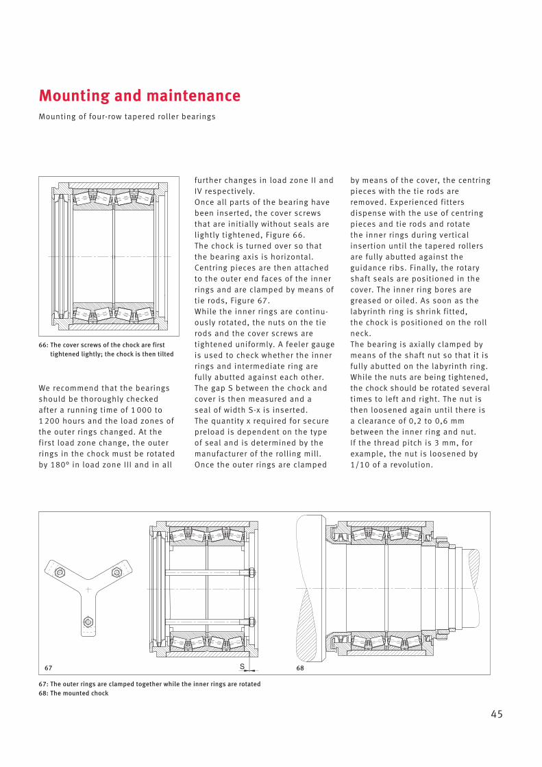
We recommend that the bearingsshould be thoroughly checkedafter a running time of 1 000 to 1 200 hours and the load zones ofthe outer rings changed. At thefirst load zone change, the outerrings in the chock must be rotatedby 180° in load zone III and in all
further changes in load zone II andIV respectively.Once all parts of the bearing havebeen inserted, the cover screwsthat are initially without seals arelightly tightened, Figure 66. The chock is turned over so thatthe bearing axis is horizontal. Centring pieces are then attachedto the outer end faces of the innerrings and are clamped by means oftie rods, Figure 67.While the inner rings are continu-ously rotated, the nuts on the tierods and the cover screws aretightened uniformly. A feeler gaugeis used to check whether the innerrings and intermediate ring are fully abutted against each other.The gap S between the chock andcover is then measured and a seal of width S-x is inserted. The quantity x required for securepreload is dependent on the typeof seal and is determined by themanufacturer of the rolling mill.Once the outer rings are clamped
Mounting and maintenanceMounting of four-row tapered roller bearings
45
66: The cover screws of the chock are firsttightened lightly; the chock is then tilted
67: The outer rings are clamped together while the inner rings are rotated68: The mounted chock
S67 68
by means of the cover, the centringpieces with the tie rods areremoved. Experienced fitters dispense with the use of centringpieces and tie rods and rotate the inner rings during verticalinsertion until the tapered rollersare fully abutted against the guidance ribs. Finally, the rotaryshaft seals are positioned in thecover. The inner ring bores aregreased or oiled. As soon as thelabyrinth ring is shrink fitted, the chock is positioned on the rollneck.The bearing is axially clamped bymeans of the shaft nut so that it isfully abutted on the labyrinth ring.While the nuts are being tightened,the chock should be rotated severaltimes to left and right. The nut isthen loosened again until there isa clearance of 0,2 to 0,6 mmbetween the inner ring and nut. If the thread pitch is 3 mm, forexample, the nut is loosened by1/10 of a revolution.
It is advisable not to grease thebearing arrangement until aftermounting, otherwise the bearingmay become contaminated. Greasing should ideally be carriedout using a grease gun. If a greasegun is not available, the roller setsmust be greased by hand beforeinsertion in the chock. In the case of rolls that are intended for very high rollingspeeds, the chocks must not bepacked completely with grease.Please consult us for informationon the quantity required in thespecific case.
Dismounting
If the chock is to be positioned onanother roll when replacing rolls,it is simply necessary to unscrewthe nut and the complete chockcan be removed from the roll neckand slid onto the new roll. If thebearings must be dismounted inmaintenance and inspection, thisis carried out on the same basis asmounting but in the reversesequence. Double row taperedroller bearings can be dismountedin the same way.
Mounting and maintenanceMounting of four-row tapered roller bearings
46
Maintenance
After a long running time, the axialinternal clearance of four-rowtapered roller bearings increasesdue to wear of the raceways. It is therefore necessary to checkthe axial internal clearance fromtime to time.If the axial internal clearance istoo large, the outer and innerintermediate rings must bereground. The corrected axial internal clearance should begreater than the original axialinternal clearance. Further information can be foundin WL 80 154.
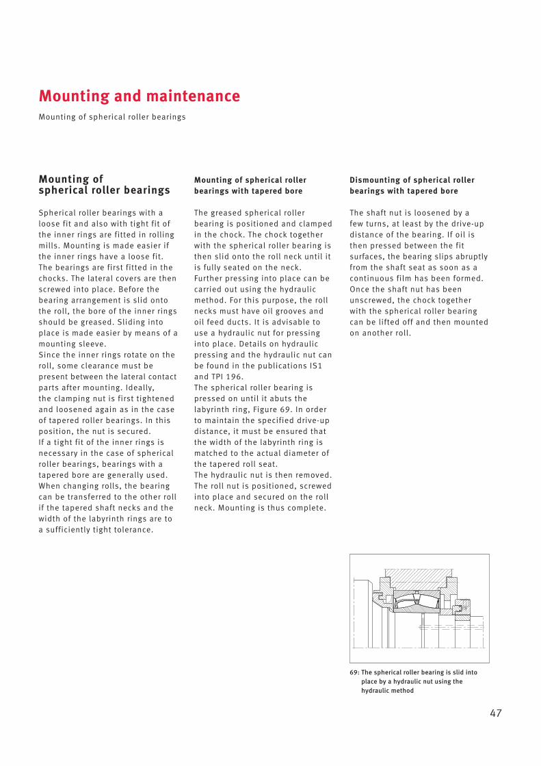
47
Mounting of spherical roller bearings
Spherical roller bearings with aloose fit and also with tight fit ofthe inner rings are fitted in rollingmills. Mounting is made easier ifthe inner rings have a loose fit.The bearings are first fitted in thechocks. The lateral covers are thenscrewed into place. Before thebearing arrangement is slid ontothe roll, the bore of the inner ringsshould be greased. Sliding intoplace is made easier by means of amounting sleeve. Since the inner rings rotate on theroll, some clearance must be present between the lateral contactparts after mounting. Ideally, the clamping nut is first tightenedand loosened again as in the caseof tapered roller bearings. In thisposition, the nut is secured. If a tight fit of the inner rings isnecessary in the case of sphericalroller bearings, bearings with atapered bore are generally used.When changing rolls, the bearingcan be transferred to the other rollif the tapered shaft necks and thewidth of the labyrinth rings are toa sufficiently tight tolerance.
Mounting of spherical roller bearings with tapered bore
The greased spherical roller bearing is positioned and clampedin the chock. The chock togetherwith the spherical roller bearing isthen slid onto the roll neck until itis fully seated on the neck. Further pressing into place can becarried out using the hydraulicmethod. For this purpose, the rollnecks must have oil grooves andoil feed ducts. It is advisable touse a hydraulic nut for pressinginto place. Details on hydraulicpressing and the hydraulic nut canbe found in the publications IS1and TPI 196. The spherical roller bearing ispressed on until it abuts thelabyrinth ring, Figure 69. In orderto maintain the specified drive-updistance, it must be ensured thatthe width of the labyrinth ring ismatched to the actual diameter ofthe tapered roll seat.The hydraulic nut is then removed.The roll nut is positioned, screwedinto place and secured on the rollneck. Mounting is thus complete.
Dismounting of spherical rollerbearings with tapered bore
The shaft nut is loosened by a few turns, at least by the drive-up distance of the bearing. If oil isthen pressed between the fit surfaces, the bearing slips abruptlyfrom the shaft seat as soon as acontinuous film has been formed.Once the shaft nut has beenunscrewed, the chock togetherwith the spherical roller bearingcan be lifted off and then mountedon another roll.
69: The spherical roller bearing is slid intoplace by a hydraulic nut using thehydraulic method
Mounting and maintenanceMounting of spherical roller bearings
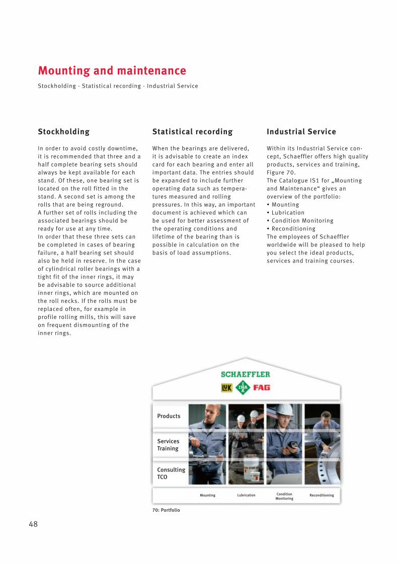
48
Stockholding
In order to avoid costly downtime,it is recommended that three and ahalf complete bearing sets shouldalways be kept available for eachstand. Of these, one bearing set islocated on the roll fitted in thestand. A second set is among therolls that are being reground. A further set of rolls including theassociated bearings should beready for use at any time. In order that these three sets canbe completed in cases of bearingfailure, a half bearing set shouldalso be held in reserve. In the caseof cylindrical roller bearings with atight fit of the inner rings, it maybe advisable to source additionalinner rings, which are mounted onthe roll necks. If the rolls must bereplaced often, for example in profile rolling mills, this will saveon frequent dismounting of theinner rings.
Statistical recording
When the bearings are delivered, it is advisable to create an indexcard for each bearing and enter allimportant data. The entries shouldbe expanded to include furtheroperating data such as tempera-tures measured and rolling pressures. In this way, an importantdocument is achieved which canbe used for better assessment ofthe operating conditions and lifetime of the bearing than is possible in calculation on thebasis of load assumptions.
Mounting and maintenanceStockholding · Statistical recording · Industrial Service
Industrial Service
Within its Industrial Service con-cept, Schaeffler offers high qualityproducts, services and training,Figure 70.The Catalogue IS1 for „Mountingand Maintenance“ gives anoverview of the portfolio:• Mounting• Lubrication• Condition Monitoring• ReconditioningThe employees of Schaeffler worldwide will be pleased to helpyou select the ideal products,services and training courses.
70: Portfolio
Products
ServicesTraining
ConsultingTCO
Mounting Lubrication Condition Monitoring
Reconditioning

49
Mounting and maintenanceStorage of rolling bearings
Storage of rolling bearings
The performance capability ofmodern rolling bearings lies at theboundaries of what is technicallyachievable. The materials, dimen-sional and geometrical tolerances,surface quality and lubricationhave been optimised for maximumlevels of function, which meansthat even slight deviations in functional areas, such as thosecaused by corrosion, can impairthe performance capacity. In orderto realise the full performancecapability of rolling bearings, it is essential to match the anti-corrosion protection, packaging,storage and handling to each other.Corrosion protection and packagingconstitute part of the bearing andare optimised such that they preserve all characteristics of theproduct at the same time as far aspossible. In addition to protectingthe surface against corrosion, this includes emergency runninglubrication, friction, lubricant compatibility, noise behaviour,resistance to ageing and compat -ibility with rolling bearing com -ponents (cage and seal material).Bearings that have been dismount-ed and will not be required forsome time must be washed, preserved immediately andpacked. Washing out should becarried out using kerosene. For preservation, smaller bearingsare dipped in anti-corrosion oil,while larger bearings should becarefully sprayed. Instead of thenpacking the bearings, they can bestored in oil.
If chocks with bearings fitted arenot required again immediately, it must be checked whether therehas been ingress of water. If this is the case, the grease packingshould of course be renewed or,for example in the case of pneu-matic oil lubrication, the bearingarrangement should be cleanedand preserved. For storage, thesides of the chocks are closed offusing sealing shields.
Storage conditions for rolling bearings
As a basic prerequisite, parts mustbe stored in a closed storage areawhich cannot be affected by anyaggressive media, such as exhaustgases from vehicles or gases, mistor aerosols of acids, lyes or salts.Direct sunlight should be avoidedsince, apart from the harmfuleffects of UV radiation, it can leadto wide temperature fluctuationsin the packaging. The temperatureshould be constant and air humidity should be as low as possible. Jumps in temperatureand increased humidity lead tocondensation.The following conditions must befulfilled:• frost-free storage, i.e. a tempera-
ture of +5 °C (this prevents formation of white frost, a maxi-mum of +2 °C is permissible forup to 12 hours per day)
• maximum temperature +40 °C (to prevent excessive drainage ofanti-corrosion oils)
• relative humidity 65 % (withchanges in temperature, up to 70 % is permissible for a maxi-mum of up to 12 hours per day).
Temperature and humidity must becontinuously monitored. This canbe carried out using a datalogger.The measurements must not betaken at intervals of no more than2 hours.At least 2 measurement pointsmust be selected: The highestpoint and the lowest point in thevicinity of an external wall atwhich the goods can be stored.Larger bearings with rings of relatively small thickness shouldnot be stored standing but flat and supported over their wholecircumference.

Notes
50

Notes
51
The following list gives a selection of the available FAG publications. Further information material is available by agreement.
Applications:GL1 Large Size BearingsPLS The Bearing Solution for Strand Guide RollersTPI 129 Back-up Rolls for Multi-roll Cold Rolling MillsTPI 148 Rolling Bearing Arrangements for ConvertersTPI 157 Split Cylindrical Roller Bearings for the Bearing Arrangements of Rolling Mill Drive ShaftsTPI 176 Lubrication of Rolling BearingsTPI 218 Sealed Spherical Roller BearingsWL 41 140 Rolling Bearings for Rolling MillsWL 43 165 Split Spherical Roller BearingsWL 83 102 Rolling Bearing Damage
Maintenance:IS1 Mounting and Maintenance of Rolling BearingsTPI 170 FAG DTECT X1sTPI 207 Reconditioning and Repair of Rolling BearingsTPI 214 FAG SmartCheckTPI WL 80-64 FAG Detector IIITPI WL 80-69 FAG ProCheckWL 80 366 FAG Wear Debris MonitorWL 80 368 Competence in MaintenanceWL 80 372 FAG DTECT X1s FlyerWL 80 374 Light the Dark
Mounting:MH1 Mounting HandbookMON 90 Mounting Manual for Grease Lubricated Split FAG Spherical Roller Bearings and HousingsPDB 27 Induction FAG Heating Devices HEATERTPI 138 Rolling Bearing TolerancesTPI 168 Arcanol Rolling Bearing GreasesTPI 180 FAG Tools for Thermal DismountingTPI 182 FAG Alignment ToolsTPI 195 FAG Pressure GeneratorsTPI 196 FAG Hydraulic NutsTPI 200 FAG Heating Devices for Mounting of Rolling BearingsWL 80-56 FAG Tools for Mechanical Mounting and Dismounting of Rolling BearingsWL 80 112 Mounting of Rolling BearingsWL 80 154 Mounting Manual: Four-row Tapered Roller BearingsWL 80 369 New Possibilities for the Heating of BearingsWL 80 376 FAG Medium Frequency Heating DeviceWL 80 382 FAG CONCEPT8 – Compact Small Lubrication Device for Grease and Oil
Selection of further FAG publications
52

Every care has been taken to ensure the
correctness of the information contained
in this publication but no liability can be
accepted for any errors or omissions.
We reserve the right to make technical
changes.
© Schaeffler Technologies AG & Co. KG
Issued: 2015, May
This publication or parts thereof may not
be reproduced without our permission.
WL 17 200 GB-D
Schaeffler Technologies
AG & Co. KG
Postfach 1260
97419 Schweinfurt
Germany
Georg-Schäfer-Straße 30
97421 Schweinfurt
Germany
Phone +49 9721 91-0
Fax +49 9721 91-3435
E-Mail [email protected]
www.schaeffler.comWL
17 2
00 /
05
/ G
B-D
/ 2
0150
51 /
Prin
ted
in G
erm
any
by k
raus