fag alignment tools top-laser: smarty2 · trummy2 ·...
TRANSCRIPT

FAG Alignment ToolsTop-Laser: SMARTY2 · TRUMMY2 · INLINE · SHIM
Technical Product Information

Contents Tools for belt and chain drives 2
Belt pulley alignment device FAG Top-Laser SMARTY2 2Belt tension measuring device FAG Top-Laser TRUMMY2 5
Tools for shaft couplings 7
Shaft alignment device FAG Top-Laser INLINE 7
Accessories for alignment 13
Shims FAG Top-Laser SHIM 13
Comparison of ordering designations 15
F’IS products, services and training –everything from a single source 16
The designation system of the INA and FAG brands hasbeen harmonised. This catalogue contains the new orderingdesignations, which are currently only valid for Europe.Customers outside Europe are requested to continue usingthe old ordering designations (please see the comparisonon page 15).

FAG Top-Laser SMARTY2
Top-Laser SMARTY2 is an economi-cal measuring device for the alignment of belt pulleys and chainsprockets. Through the use of this device, thewear of belts, belt pulleys, bearingsand seals is reduced. Less vibrationis generated and the running timeand reliability of the machinery isincreased.
Features and advantages
• Display of parallelism and misalignment of both pulleys
• Significantly quicker and moreprecise than other, conventionalmethods
• Suitable for both horizontally andvertically mounted machinery
• Only one person required foralignment
• System can also be used on non-magnetic sprockets or pulleys
Tools for belt and chain drivesBelt pulley alignment device FAG Top-Laser SMARTY2
2
Types of misalignment
Vee beltsFlat belts
Toothed belts Chain sprockets
Main applications
Alignment of belt pulleys
Angular misalignment+ parallel misalignment
Angular misalignment
Parallel misalignment

Easy to use
The FAG Top-Laser SMARTY2 can bemounted in just a few seconds. The laser beam can be clearly seenon the target marks. Once the laserbeam is adjusted to coincide withthe slots in the target marks, the machine is correctly aligned. Nothing could be simpler.
Target marksThe target marks are available inoptical and digital form. In the caseof the digital target mark, adjust-ment values are shown in real timein the display. Angular misalign-ments are presented in degreesand the parallelism offset in mm.This allows simple documentationof the alignment process.
Aluminium pulleysSince the measuring instrument isso light, the emitter and targetmarks can be easily attached tonon-magnetic drive pulleys using astrong, double-sided adhesivetape.
Laser beam adjustmentThe laser beam emitted by the measuring instrument is adjustedparallel to the magnetic holders ofthe measuring instrument. If a devi-ation is found, this can be checkedlocally on a flat surface by the operator and readjustment carriedout if necessary.
Tools for belt and chain drivesBelt pulley alignment device FAG Top-Laser SMARTY2
3
FAG Top-Laser SMARTY2 in operation
Alignment example using a belt drive
For drives with pulleys of different widths, themarks should be moved within the target marks
B
B
A
B
A
A BANot precisely aligned Precisely aligned

Tools for belt and chain drivesBelt pulley alignment device FAG Top-Laser SMARTY2
4
Technical data
Laser emitterBelt pulleys ≥ 60 mm ø ≥ 2,36 in øLaser beam angle 78°Laser class 2Measurement distance 10 m 32,81 feetBatteries 1 ~ R6 (AA) 1,5 VBattery life 8 h continuousOutput power < 1 mWLaser wavelength 635...670 nmHousings ABS plastic, aluminiumDimensions W ~ H ~ D 145 ~ 86 ~ 30 mm 5,71 ~ 3,39 ~ 1,18 inMass 270 g 0,59 lbs
Targets 2 magnetic target marks
Measurement accuracy better than 0,5 mm / 0,02 in or 0,2° *)
*) General rule for deviations (depending on belt type):less than 0,25° [4,4 mm/m]
Ordering designation andscope of delivery:
Laser measuring instrument, com-plete, including 2 target marks, 2 batteries and user manual in padded case:LASER-SMARTY2
Replacement part:1 optical magnetic target markLASER-SMARTY2.TARGET
Accessories:1 digital magnetic target mark incl.1 case for digital magnetic targetmark and FAG Top-Laser SMARTY2LASER-SMARTY2.TARGET-DIGITAL
Safety adviceDo not look into the laser beam. Do not point the laser beam intoother persons’ eyes.
FAG Top-Laser SMARTY2
Digital magnetic target mark (accessory)

FAG Top-Laser TRUMMY2
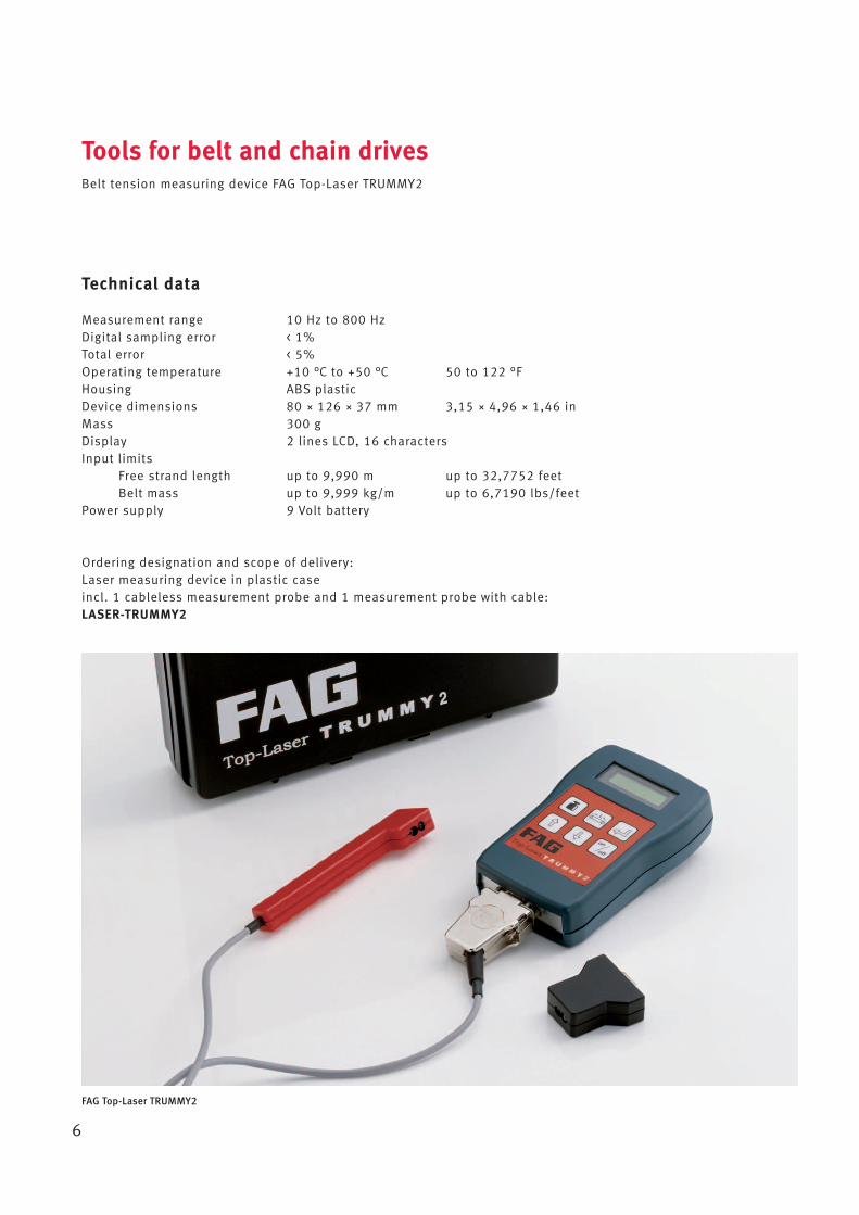
The robust, handy Top-Laser TRUMMY2 is an optical-electronicinstrument for measuring and setting optimum belt tension(strand force). Through the use ofthis device, the maximum outputand and optimum life of beltdrives, bearings and seals can beachieved.
Features and advantages
• Maximum life of belt drives canbe ensured
• Reduced wear of drive components• Reduced energy costs and
increased cost-efficiency• Absolutely reliable results due
to new measurement method(clock pulse light)
• Simple and easy to use• Multilingual operator interface
Easy to use
The user-friendly Top-Laser TRUMMY2can be used in many locations andcomprises a cableless measure-ment probe, a measurement probewith cable for difficult to accesslocations and a microprocessorthat indicates relevant measurablesfor belt tension either as frequency[Hz] or force [N]. By means of animpulse (for example by strikingthe stationary belt), the tensionedbelt is excited to natural vibration.
Tools for belt and chain drivesBelt tension measuring device FAG Top-Laser TRUMMY2
5
The individual static naturalfrequency thus generated ismeasured within seconds by theTRUMMY2 sensor using clock pulselight and displayed. In order to calculate the strand force of thebelt drive, the belt mass and lengthare entered in the microcomputerbefore measurement. TRUMMY2uses these to calculate the strandforce, which is then compared withthe specified nominal value.
Measurement using cableless measurement probe
Technical data
Measurement range 10 Hz to 800 HzDigital sampling error < 1%Total error < 5%Operating temperature +10 °C to +50 °C 50 to 122 °FHousing ABS plasticDevice dimensions 80 ~ 126 ~ 37 mm 3,15 ~ 4,96 ~ 1,46 inMass 300 gDisplay 2 lines LCD, 16 charactersInput limits
Free strand length up to 9,990 m up to 32,7752 feetBelt mass up to 9,999 kg/m up to 6,7190 lbs/feet
Power supply 9 Volt battery
Ordering designation and scope of delivery:Laser measuring device in plastic caseincl. 1 cableless measurement probe and 1 measurement probe with cable:LASER-TRUMMY2
Tools for belt and chain drivesBelt tension measuring device FAG Top-Laser TRUMMY2
6
FAG Top-Laser TRUMMY2

FAG Top-Laser INLINE
More than half of all unplannedmachine downtime can be attributedto misalignment and imbalance.These problems can also arise in theuse of flexible couplings.
The FAG Top-Laser INLINE is a PC-based system for aligning coupled shafts which can be usedto significantly increase the availability of machinery.
Tools for shaft couplingsShaft alignment device FAG Top-Laser INLINE
7
ApplicationThe FAG Top-Laser INLINE is suit-able for aligning coupled shafts inmotors, pumps, ventilators andgearboxes (with rolling bearings).
Features and advantages• Simple to mount• Error-free handling even by
untrained personnel due to automatic measurement and positioning process
• More precise alignment than withconventional methods(dial gauge and straight edge)
• Rapid measurement by “Continu-ous Sweep” (continuous rotarymotion/patented method); 70° rotary motion is adequate for measurement (any positionand rotary motion)
• Optimised measurement by“Single Beam Technology” (double laser travel distancethrough reflection)
• Reduced vibration and frictionlosses
• Increased productivity throughlonger machine running times
• Significantly lower energyconsumption
• Suitable for use with standardlaptop via PCMCIA interface
Scope of delivery:1 transceiver (incl. 3 m cable)1 reflector2 brackets2 chains (300 mm)4 posts (115 mm)1 software (manual, help CD)1 case1 serial PC card
Ordering designation: Complete FAG Top-Laser INLINE:LASER-INLINE
Case PC card Software
Post
Chain Bracket Transceiver
Cable
Reflector
FAG Top-Laser INLINE in operation
Scope of delivery of FAG Top-Laser INLINE
Actions before alignment
Before any alignment operation,any tilting foot (machine foot thatlifts off the floor when slackened)should be removed in order to pre-vent increased vibration tendencyand bearing damage due to housingdistortion. The Top-Laser INLINE helps toquickly identify and eliminate theso-called soft foot. It is onlynecessary to loosen each individualscrew foot connection. The computerdetermines any foot movement. The foot tilt can then be eliminatedusing shims (see page 13).
Tools for shaft couplingsShaft alignment device FAG Top-Laser INLINE
8
Accessories
The possible applications of theLASER-INLINE basic device can beexpanded with the aid of a compre-hensive range of accessories. The accessories can be ordered asa set in a handy, robust case or –individually compiled – asindividual parts.
Software with soft foot
Scope ofdelivery
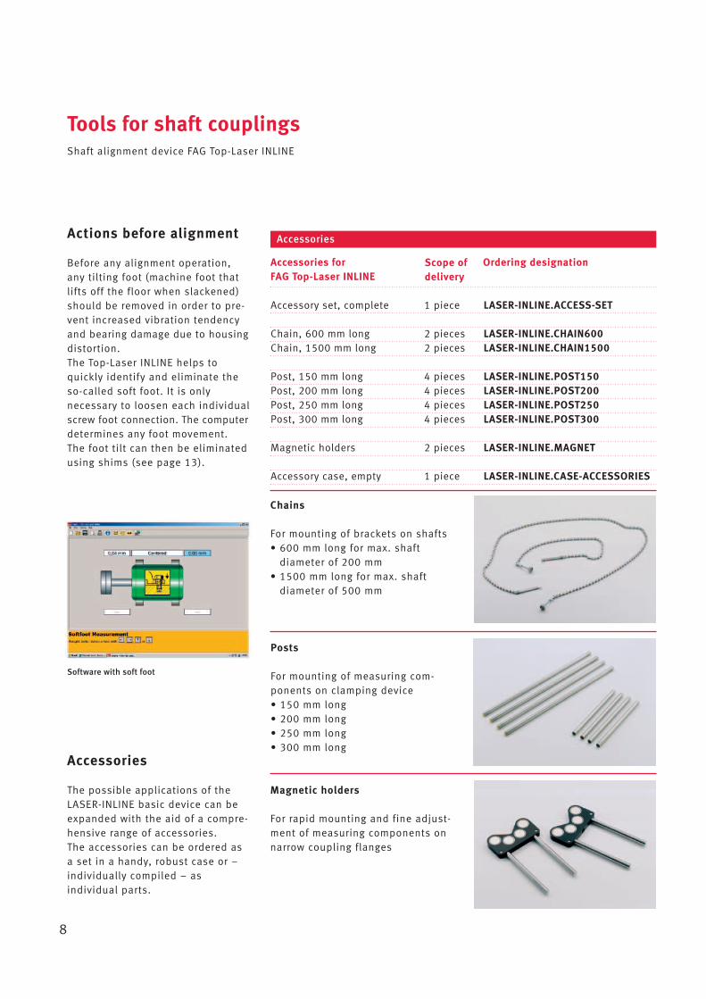
Chains
For mounting of brackets on shafts• 600 mm long for max. shaft
diameter of 200 mm• 1500 mm long for max. shaft
diameter of 500 mm
Accessory set, complete 1 piece LASER-INLINE.ACCESS-SET
Chain, 600 mm long 2 pieces LASER-INLINE.CHAIN600Chain, 1500 mm long 2 pieces LASER-INLINE.CHAIN1500
Post, 150 mm long 4 pieces LASER-INLINE.POST150Post, 200 mm long 4 pieces LASER-INLINE.POST200Post, 250 mm long 4 pieces LASER-INLINE.POST250Post, 300 mm long 4 pieces LASER-INLINE.POST300
Magnetic holders 2 pieces LASER-INLINE.MAGNET
Accessory case, empty 1 piece LASER-INLINE.CASE-ACCESSORIES
Accessories for Ordering designationFAG Top-Laser INLINE
Accessories
Posts
For mounting of measuring com-ponents on clamping device• 150 mm long• 200 mm long• 250 mm long• 300 mm long
Magnetic holders
For rapid mounting and fine adjust-ment of measuring components onnarrow coupling flanges

Tools for shaft couplingsShaft alignment device FAG Top-Laser INLINE
9
2 chains, available inlengths 300, 600, 1500 mm
For max. shaft diameters 100 mm,200 mm, 500 mm for mounting ofbrackets on shafts
Ordering designations:LASER-INLINE.CHAIN300LASER-INLINE.CHAIN600LASER-INLINE.CHAIN1500
Transceiver
Compact, robust transceiver forvisible laser beam (red)
Ordering designation:LASER-INLINE.TRANS
Reflector
Roof prism with compact housing,mounted on clamping device bymeans of lever
Ordering designation:LASER-INLINE.REFLECT
Bracket
Basic element of compact chainclamping device
Ordering designation:LASER-INLINE.BRACKET
Cable
For supplying power to transceiverand exchanging data with controlunit
Ordering designation:LASER-INLINE.CABLE
Cable
Transceiver

4 posts, available inlengths 115 mm, 150 mm, 200 mm, 250 mm, 300 mmFor mounting of measuring components on clamping device
Ordering designations:LASER-INLINE.POST115LASER-INLINE.POST150LASER-INLINE.POST200LASER-INLINE.POST250LASER-INLINE.POST300
Software
Windows-compatible PC programfor storage of machine dimensionsand alignment conditions, evaluation and printing of results
Ordering designation:LASER-INLINE.SOFTW
Case
Black plastic case with foam insertfor safe transport of the device
Ordering designation:LASER-INLINE.CASE
PC card (type II)
Insertion in PC for connection toFAG Top-Laser INLINE
Ordering designation:LASER-INLINE.PCCARD
Tools for shaft couplingsShaft alignment device FAG Top-Laser INLINE
10
Tools for shaft couplingsShaft alignment device FAG Top-Laser INLINE
11
Easy to use
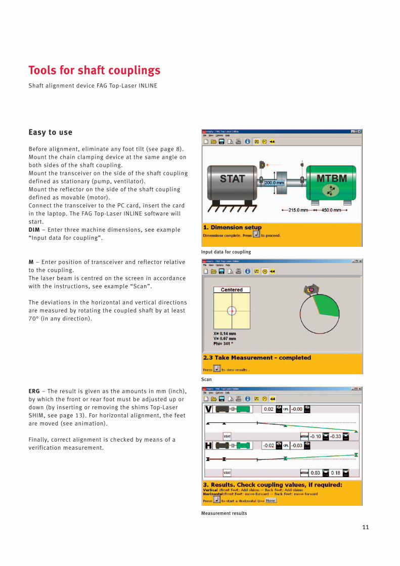
Before alignment, eliminate any foot tilt (see page 8).Mount the chain clamping device at the same angle onboth sides of the shaft coupling.Mount the transceiver on the side of the shaft couplingdefined as stationary (pump, ventilator).Mount the reflector on the side of the shaft couplingdefined as movable (motor).Connect the transceiver to the PC card, insert the cardin the laptop. The FAG Top-Laser INLINE software willstart.DIM – Enter three machine dimensions, see example“Input data for coupling”.
M – Enter position of transceiver and reflector relativeto the coupling.The laser beam is centred on the screen in accordancewith the instructions, see example “Scan”.
The deviations in the horizontal and vertical directionsare measured by rotating the coupled shaft by at least70° (in any direction).
ERG – The result is given as the amounts in mm (inch),by which the front or rear foot must be adjusted up ordown (by inserting or removing the shims Top-LaserSHIM, see page 13). For horizontal alignment, the feetare moved (see animation).
Finally, correct alignment is checked by means of averification measurement.
Measurement results
Scan
Input data for coupling

Tools for shaft couplingsShaft alignment device FAG Top-Laser INLINE
12
Technical data
Transceiver
Measurement method: coaxial, reflected laser beamProtection class: IP67 (dustproof, water proof under temporary immersion)Protection against ambient light: yesStorage: –20 to +80 °C –4 to +176 °FOperation: 0 to 55 °C 32 to 131 °FDimensions (W ~ H ~ D): approx. 107 ~ 70 ~ 49 mm approx. 4,213 ~ 2,756 ~ 1,929 inMass: approx. 177 g approx. 0,39 lbs
Laser (Ga-Al-As semiconductor laser)
Wavelength (typical): 670 nm (red, visible)Laser class: 2; FDA 21CFR 1000 & 1040Beam power: < 1 mWInterface: Serial I/0 PCMCIA card, type IIMax. distance: 3m 9,84 feet
Detector
Measurement range: ± 4 mm ± 0,157 inResolution: 1 μmAccuracy: better than 2 %
Inclinometer
Measurement range: 0 to 360°Resolution: less than 1°
Reflector
Type: 90° roof prismProtection class: IP67 (dustproof, waterproof under temporary immersion)Accuracy: better than 1 %Storage: –20 to +80 °C –4 to +176 °FOperation: –20 to +60 °C –4 to +140 °FDimensions (W ~ H ~ D): approx. 100 ~ 41 ~ 35 mm approx. 3,937 ~ 1,614 ~ 1,378 inMass: approx. 65 g approx. 0,143 lbs
Carry case
Material: standard ABS, black, drop tested (2 m)Dimensions (W ~ H ~ D): approx. 470 ~ 400 ~ 195 mm approx. 18,503 ~ 15,748 ~ 7,677 inMass with standard components: approx. 6,8 kg approx. 15 lbs
Range of application
Shaft diameter: min. 12 mm, max. 500 mm (with accessories) min. 0,472 in, max. 19,685 in
Accessories for alignmentShims FAG Top-Laser SHIM
13
FAG Top-Laser SHIM
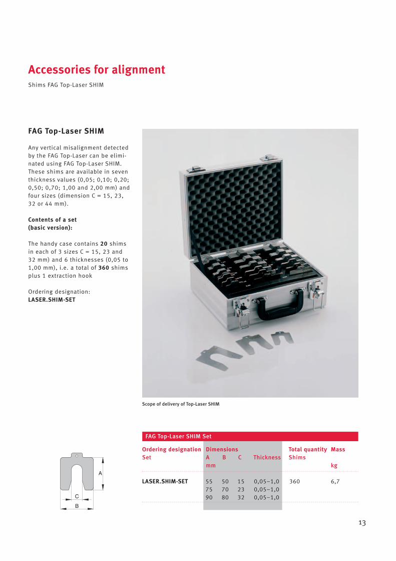
Any vertical misalignment detectedby the FAG Top-Laser can be elimi-nated using FAG Top-Laser SHIM.These shims are available in seventhickness values (0,05; 0,10; 0,20;0,50; 0,70; 1,00 and 2,00 mm) andfour sizes (dimension C = 15, 23,32 or 44 mm).
Contents of a set(basic version):
The handy case contains 20 shimsin each of 3 sizes C = 15, 23 and32 mm) and 6 thicknesses (0,05 to1,00 mm), i.e. a total of 360 shimsplus 1 extraction hook
Ordering designation:LASER.SHIM-SET
LASER.SHIM-SET 55 50 15 0,05–1,0 360 6,775 70 23 0,05–1,090 80 32 0,05–1,0
Ordering designation Dimensions Total quantity MassSet A B C Thickness Shims
mm kg
FAG Top-Laser SHIM Set
C
B
A
Scope of delivery of Top-Laser SHIM

Accessories for alignmentShims FAG Top-Laser SHIM
14
Number ofshims
Individual or spare parts
As individual or spare parts, wesupply 10 shims each in one of thefour sizes stated above (dimension C = 15, 23, 32 or 44 mm)and one of the seven thicknesses.
Ordering examples:
• 10 shims each of dimension C = 15 mm and 0,20 mm thickness:LASER.SHIM15X0,20
• 10 shims each of dimension C = 44 mm and 0,10 mm thickness:LASER.SHIM44X0,10
• 10 shims each of dimension C = 23 mm and 2,00 mm thickness:LASER.SHIM23X2,00
LASER.SHIM15X0,05 55 50 15 0,05 10 11LASER.SHIM15X0,10 55 50 15 0,10 10 22LASER.SHIM15X0,20 55 50 15 0,20 10 44LASER.SHIM15X0,50 55 50 15 0,50 10 110LASER.SHIM15X0,70 55 50 15 0,70 10 155LASER.SHIM15X1,00 55 50 15 1,00 10 220LASER.SHIM15X2,00 55 50 15 2,00 10 440
LASER.SHIM23X0,05 75 70 23 0,05 10 21LASER.SHIM23X0,10 75 70 23 0,10 10 42LASER.SHIM23X0,20 75 70 23 0,20 10 84LASER.SHIM23X0,50 75 70 23 0,50 10 210LASER.SHIM23X0,70 75 70 23 0,70 10 295LASER.SHIM23X1,00 75 70 23 1,00 10 420LASER.SHIM23X2,00 75 70 23 2,00 10 840
LASER.SHIM32X0,05 90 80 32 0,05 10 29LASER.SHIM32X0,10 90 80 32 0,10 10 58LASER.SHIM32X0,20 90 80 32 0,20 10 115LASER.SHIM32X0,50 90 80 32 0,50 10 290LASER.SHIM32X0,70 90 80 32 0,70 10 410LASER.SHIM32X1,00 90 80 32 1,00 10 580LASER.SHIM32X2,00 90 80 32 2,00 10 1160
LASER.SHIM44X0,05 125 105 44 0,05 10 53LASER.SHIM44X0,10 125 105 44 0,10 10 105LASER.SHIM44X0,20 125 105 44 0,20 10 210LASER.SHIM44X0,50 125 105 44 0,50 10 530LASER.SHIM44X0,70 125 105 44 0,70 10 740LASER.SHIM44X1,00 125 105 44 1,00 10 1050LASER.SHIM44X2,00 125 105 44 2,00 10 2100
Ordering designation Dimensions MassA B C Thickness
FAG mm g
Individual parts and spare parts for FAG Top-Laser SHIM
C
B
A

Ordering designation for Europe Ordering designation for countries outside Europe
LASER-INLINE LASER.INLINELASER-INLINE.ACCESS-SET LASER.INLINE.ACCESS.SETLASER-INLINE.BRACKET LASER.INLINE.BRACKETLASER-INLINE.CABLE LASER.INLINE.CABLELASER-INLINE.CASE LASER.INLINE.SUITCASELASER-INLINE.CASE-ACCESSORIES LASER.INLINE.ACCESS.SUITCASELASER-INLINE.CHAIN300 (~600; ~1500) LASER.INLINE.CHAIN300 (~600; ~1500)LASER-INLINE.MAGNET LASER.INLINE.MAGNETLASER-INLINE.PCCARD LASER.INLINE.PCCARDLASER-INLINE.POST115 (~150; ~200; ~250; ~300) LASER.INLINE.POST115 (~150; ~200; ~250; ~300)LASER-INLINE.REFLECT LASER.INLINE.REFLLASER-INLINE.SOFTW LASER.INLINE.SOFTWARELASER-INLINE.TRANS LASER.INLINE.TRANS
LASER.SHIM-SET LASER.SHIMS.SETLASER.SHIM15X0,05 (~0,10; ~0,20 ... ~2,00) LASER.SHIMS15.0,05 (~0,10; ~0,20 ... ~2,00)LASER.SHIM23X0,05 (~0,10; ~0,20 ... ~2,00) LASER.SHIMS23.0,05 (~0,10; ~0,20 ... ~2,00)LASER.SHIM32X0,05 (~0,10; ~0,20 ... ~2,00) LASER.SHIMS32.0,05 (~0,10; ~0,20 ... ~2,00)LASER.SHIM44X0,05 (~0,10; ~0,20 ... ~2,00) LASER.SHIMS44.0,05 (~0,10; ~0,20 ... ~2,00)
LASER-SMARTY2 LASER.SMARTY2LASER-SMARTY2.TARGET LASER.SMARTY2.TARGETLASER-SMARTY2.TARGET-DIGITAL LASER.SMARTY2.TARGET.DIGITAL
LASER-TRUMMY2 LASER.TRUMMY2
Comparison of ordering designations
15

FAG Industrial Services (F’IS) is afull service supplier in the field ofcondition-based maintenance.With the sourcing of high qualityF’IS products, the customer thusgains access to a range of product-oriented services relating to rollingbearings: from mounting, throughmaintenance to reconditioning ofrolling bearings (see diagram).
In the field of alignment, F’IS offersnot only service products but alsoprofessional alignment as a service.Where necessary, the F’IS servicetechnician will take the necessarylaser alignment system to the customer and carry out alignmentof the machine in accordance withthe manufacturer’s specifications. Successful completion of the workis then documented.
F’IS products, services and training – everything from a single source
16
On the basis of product presen-tations, we will be pleased toinstruct our customers wherenecessary in the use and handlingof alignment devices so that theyare then in a position to carry outsuch alignment work themselves.If you have any further questionson our services, please contact usdirect or visit our website.
Services relating torolling bearingsReconditioning of
rolling bearings
Technicalconsultancy
Customer training
Lubrication
Mounting
TribologyMaterials,coatingsRolling bearing
technology /design
Correctivemaintenance• Balancing• Alignment
Condition monitoring• Online and offline
measurement• E-service• Thermography• Modal analysis• etc.

MAT
NR
0355
8260
0-00
00 /
200
8022
/ P
rint
ed in
Ger
man
yby
Dru
ckha
usW
eppe
rtG
mbH
Every care has been taken to ensure the
correctness of the information contained
in this publication but no liability can be
accepted for any errors or omissions.
We reserve the right to make technical
changes.
© Schaeffler KG · 2008, February
This publication or parts thereof may not
be reproduced without our permission.
TPI WL 80-55/3 EA
Schaeffler KG
Postfach 1260
97421 Schweinfurt (Germany)
Georg-Schäfer-Strasse 30
97421 Schweinfurt (Germany)
Phone +49 2407 9149-66
Fax +49 2407 9149-59
E-Mail [email protected]
Internet www.fis-services.com