facility review flathead indian irrigation project pumping
TRANSCRIPT

U.S. Department of the Interior Bureau of Reclamation December 17, 2014
Facility Review Flathead Indian Irrigation Project Pumping Plants


Table of Contents REVIEW TEAM ............................................................................................................................ 1
EXECUTIVE SUMMARY ............................................................................................................... 2
OBJECTIVE .................................................................................................................................. 2
FLATHEAD LAKE PUMPING PLANT ........................................................................................................ 2 Landslide Area ......................................................................................................................... 2 Flathead Lake Pumping Plant Structure .................................................................................. 5 Flathead Lake Pumping Plant Access Road ............................................................................. 7 Photograph 7: Looking from the BIA Flathead Lake Pumping Plant along the access road at a landslide area next to the road. ........................................................................................... 8 Penstocks ................................................................................................................................ 8 Concrete-Lined Discharge Canal ............................................................................................. 8 Electrical Features/Substation and Transformer .................................................................. 10 Substation Modernization and Protection Recommendations ............................................. 10 Circuit Breakers and Motors ................................................................................................. 13 Oil Circuit Breakers ................................................................................................................ 15 Excitation Auto Transformers in Lower Gallery .................................................................... 17 Circuit Breakers and Motors Modernization Recommendation............................................ 17 Plant Auxiliary Circuit Breaker Panel .................................................................................... 17 Plant DC Battery System ....................................................................................................... 18 Plant Personnel Protective Equipment (PPE) ........................................................................ 18 Synchronous Motor Excitation System.................................................................................. 18 Mechanical Systems .............................................................................................................. 20 Pumps ................................................................................................................................... 20 Bearing Oil System ................................................................................................................ 21 Plant Crane ........................................................................................................................... 21
CROW CREEK PUMPING PLANT ......................................................................................................... 22 Civil Features ......................................................................................................................... 22 Electrical Features ................................................................................................................. 24
REVAIS PUMPING PLANT .................................................................................................................. 25 Electrical Features ................................................................................................................. 25
COST ESTIMATE INFORMATION ............................................................................................... 27
REVIEW MATERIAL ......................................................................................................................... 31
CONTACT LIST .......................................................................................................................... 32


1
Review Team Bureau of Reclamation (BOR), Pacific Northwest Regional Office, Boise ID
Jeffrey Garner, Mechanical Engineer, Power Operations and Maintenance Robert Ross, Electrical Engineer, Power Operations and Maintenance Sonja Norton, Civil Engineer, Facility Operations and Maintenance
Additional Attendees: Bureau of Indian Affairs (BIA)
Jeff Harlan, Irrigation Engineer Pete Plant, Supervisory Civil Engineer Reed Anderson, Powerplant Operator
Confederated Salish and Kootenai Tribes (Tribe) Natural Resources Department
Seth Makepeace, Hydrologist Craig Barfoot, Fishery Biologist
Dowl HKM, Helena MT
Jeffrey K. Olsson, Water Resources Engineer Montana State (present only at the Flathead Lake Pumping Plant)
Stan Jones, Hydrologist, Reserved Water Rights Compact Commission Kevin Smith, Department of Natural Resources State Water Projects Bureau Chief Ethan Mace, Hydrologist Larry Schock, Civil Engineer
2
Executive Summary As part of the Salish –Kootnai Tribal Water Rights Negotiations, the Confederated Salish & Kootenai Tribes (CSKT or Tribes), the State of Montana, and the United States government have been working for several years to develop a water rights settlement that will determine the water rights of the CSKT and the water right for the Flathead Indian Irrigation Project (FIIP) which is located on the Flathead Indian Reservation. Since the FIIP is integral to delivering a portion of CSKT’s water right, concerns about the current condition of facilities and future costs to operate and maintain them needed to be evaluated to inform negotiations moving forward. A Facility Review of the Flathead Pumping Plants which are component of the FIIP was conducted on December 17, 2014 by the Bureau of Reclamation. The purpose of the review was to perform a site visit, document the current condition of the pumping plants and provide a cost estimate for repairs, modifications and/or replacement. The facility review was requested by Duane Mecham chair of the Department of the Interior’s Flathead Water Rights Negotiations team.
Objective The purpose of this site visit was to review the existing facilities, document the current condition of the facilities, and provide a cost estimate for repairs, modifications and/or replacement needs for the Flathead Lake, Crow Creek, and Revais Pumping Plants.
The costs of the environmental evaluations, design, and contract administration associated with any modifications or replacement of any features or facility are not included in this report.
Flathead Lake Pumping Plant Landslide Area
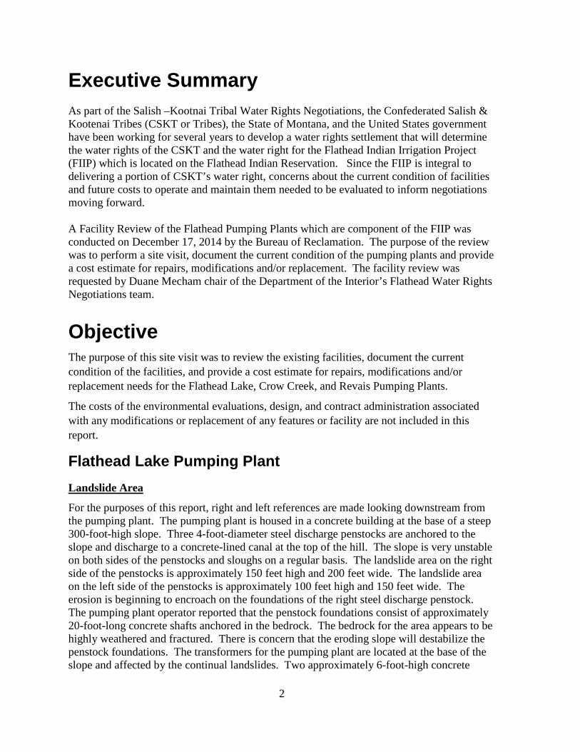
For the purposes of this report, right and left references are made looking downstream from the pumping plant. The pumping plant is housed in a concrete building at the base of a steep 300-foot-high slope. Three 4-foot-diameter steel discharge penstocks are anchored to the slope and discharge to a concrete-lined canal at the top of the hill. The slope is very unstable on both sides of the penstocks and sloughs on a regular basis. The landslide area on the right side of the penstocks is approximately 150 feet high and 200 feet wide. The landslide area on the left side of the penstocks is approximately 100 feet high and 150 feet wide. The erosion is beginning to encroach on the foundations of the right steel discharge penstock. The pumping plant operator reported that the penstock foundations consist of approximately 20-foot-long concrete shafts anchored in the bedrock. The bedrock for the area appears to be highly weathered and fractured. There is concern that the eroding slope will destabilize the penstock foundations. The transformers for the pumping plant are located at the base of the slope and affected by the continual landslides. Two approximately 6-foot-high concrete

3
walls are located at the base of the slope, between the slope toe and the transformers, to reduce the amount of debris falling into the transformer yard. The slope should either be stabilized with a massive concrete retainer or soil reinforcement structure, or by reducing the angle of the slope. It is not known if the project owns a sufficient amount of land at the top of the slope to reduce the angle of the slope. It is anticipated that the slope would have to be no greater than 1½-horizontal-foot to 1-vertical-foot and possibly 2-horizontal to 1-vertical-foot to stabilize the area. Geological data and field explorations (drill holes) would be required in order to determine a slope stabilization method. These field exploration costs are not included in the cost estimate provided in this report.
Photograph 1: Aerial photograph of Flathead Lake Pumping Plant showing the landslides on both sides of the three penstocks.

4
Photograph 2: Looking at the landslide area to the right of the Flathead Lake Pumping Plant discharge penstocks.
Photograph 3: Landslide area and three discharge penstocks for the Flathead Lake Pumping Plant.

5
Flathead Lake Pumping Plant Structure The pumping plant intake structure consists of a five-bay concrete structure with slots for boards at the upstream end. The two end bays are not used. Trashracks are located about 10 feet downstream fromthe upstream end of the intake structure in each of the three pump bays. Slide gates are located immediately downstream of the trashracks in each of the three pump bays. The slide gates are operated with a portable drill. The 15-foot-high trashracks must be cleaned manually using a rake. The quantity of debris is reported to be variable. A motor-operated trashrack cleaning system should be provided to eliminate injuries to operating personnel. In order to limit the amount of debris on the trashracks, a timber is placed across the upstream end of each bay. The timbers must be placed and removed manually. No walkways with appropriate safety railing are provided on the intake structure. An overhead crane and appropriate safety compliant walkways should be provided to allow personnel to lower the boards in place.
Photograph 4: Looking left across the top of the Flathead Lake Pumping Plant intake structure.
Three pumps with a total capacity of 210 ft3/s are located in each of the bays downstream from the slide gates. Each pump discharges water to a steel penstock, which extends up the approximately 300-foot-high slope to a concrete outlet structure and concrete-lined canal. Flap gates are installed on the downstream end of each penstock. The concrete outlet structure was in satisfactory condition and no problems were reported with the flap gates.
6
Photograph 5: Aerial photograph of Flathead Lake Pumping Plant, three discharge penstocks, and the canal.
The single pane windows in the pumping plant building should be replaced. Many of the windows were broken or cracked. The three windows on the upstream side of the building consist of 8 rows and 4 columns of rectangular panes. Each pane is 25 inches high by 38 inches long. Four smaller windows are installed on the downstream side of the building. It is anticipated that the building is a historical structure and that the replacement windows will have to be approved by the Montana State Historic Preservation Office and similar in appearance to the existing.
A seismic evaluation of the pumping plant building has not been performed and should be prior to any modifications. In addition, life safety code, fire protection, and Americans with Disability Act (ADA) reviews and assessments should be performed. Any recommended repairs or retrofits recommended as a result of these evaluations should be incorporated into the modification of the pumping plant.
The roof on the pumping plant structure has not been replaced since construction. It is not known what type of roof was installed but it likely needs to be replaced.

7
Photograph 6: Looking down the penstocks at the downstream side of the Flathead Lake Pumping Plant building.
Flathead Lake Pumping Plant Access Road
There are several landslides along the dirt road to the Flathead Lake Pumping Plant which are continually sloughing material onto the road. The number of landslides areas along the road were not counted during this site visit. Stabilizing these areas would require geologic investigations. Slope stabilization would likely be expensive. The cost to stabilize these areas is not provided or considered in this report.

8
Photograph 7: Looking from the BIA Flathead Lake Pumping Plant along the access road at a landslide area next to the road.
Penstocks The metal thickness of the penstocks has not been measured since construction and should be obtained and evaluated. The powerplant operator reported the penstocks had not been coated since original construction. In addition, pin-sized holes have been observed by operating personnel and repaired by welding additional material in the hole. Some small areas of corrosion were observed on the penstocks, especially along the bottom. At the very least, the exterior of the penstocks should be cleaned and coated. Depending upon the metal thickness data, the penstock may need to be reinforced with steel or replaced. A thorough evaluation of the penstocks should be performed. Each penstock is secured to the concrete foundations with steel stirrups, which are hinged at the base to allow temperature induced expansion and contraction of the penstocks. Grease circs are provided in the hinge and are lubricated periodically. The hinge pins should be regularly inspected for cracks and distortion.
Concrete-Lined Discharge Canal The concrete-lined canal is approximately 1½ miles long and water can be checked in the canal to provide water in both directions. A few hundred feet downstream from the concrete outlet structure, a second concrete liner was placed on top of the original lining. However, the top of the second liner is below the top of the original liner. As a result, water flows between the two concrete liners. According to the powerplant operator, several seepage areas are located along the canal in cut sections. The seepage areas should be monitored on a daily basis during the irrigation season. In order to reduce and control the seepage areas, the canal embankment should be excavated and a drain system, consisting of perforated pipe in a sand and gravel filter, should be installed to collect the seepage and the embankment rebuilt with compacted soils. A nonperforated section of pipe should be installed on the end of the

9
perforated pipe to convey flows downstream of the embankment toe. If the drain does not control the seepage, it may be necessary to reconstruct the concrete lining along the seepage areas. No displaced or severely deteriorated concrete panels were reported or observed. The addition of the second concrete-liner has reduced the carrying capacity of the trapezoidal cross-section canal so that the maximum water level is only a few inches below the top of the original concrete lining. If water was to overtop the concrete liner, the fill sections of the embankment might become unstable and fail. In order to provide adequate freeboard, the top of the original concrete liner should be raised by about 1 foot.
Photograph 8: Looking at the portion of the canal from the Flathead Lake Pumping Plant with a second concrete liner.

10
Photograph 9: Looking at the gap between the second and original concrete liners.
Electrical Features/Substation and Transformer The substation consists of three oil filled transformers, each with 2.4-kilovolt (kV)/34.5-kV, rated at 2,500 kilovolt ampere (kVA). Transformers are connected in a parallel Delta/Delta configuration. The main transformers appear to have been replaced and upgraded in the last 10 years and appear to be in relatively good condition. Currently, maintenance is performed by the local utility company, Mission Valley Power, which includes periodic inspection and oil analysis. The 34.5-kV lightning surge protection, high side disconnects, and fuses are located on the north side of the substation. A 100-kVA transformer provides station service to the pumping plant.
Substation Modernization and Protection Recommendations While the substation is in relatively good condition, the most significant hazard to the substation are the multiple boulders located upslope above the pumping plant. These boulders periodically roll into the substation, causing damage to the transformer and overhead support structure. The pumping plant operator stated that the reason for the transformer replacement was because boulders jump the concrete wall and strike the transformer. The substation is severely lacking in electrical protective relaying. Recommended relay protection to include the following:

11
• Instrument transformers, potential transformers, and current transformers to feed the proposed protective relays.
• Overcurrent (50/51) relays. • Under voltage (27). • Phase sequence relay (47). • Volts per hertz.
Note - Some relaying functions may be located in the pump house.
Photograph 10: View of Flathead Lake Pumping Plant substation auxiliary transformer and disconnects.

12
Photograph 11: View of Flathead Lake Pumping Plant substation main transformers.
Photograph 12: Looking at the concrete retaining walls provided at the toe of the steep slope downstream of the transformer.
Photo shows rocks that have rolled down the hill

13
Photograph 13: Photo shows deterioration of cables in substation.
Circuit Breakers and Motors Three Elliott Co. Ridgeway Works synchronous motors, each rated at 3,000 horsepower, 2,300 volts, and 900 revolutions per minute (rpm) drive Worthington centrifugal pumps located in the lower gallery. At the time of the site visit, Pump No. 2 was down for major repair on the motor brush assembly due to arcing of the assembly to ground.
Photograph 14: Flathead Lake Pumping Plant exciter.

14
Above photos show exciter upper section with brush assembly removed. Plant operator stated that parts for motors are extremely rare and expensive. Other motors have had failures in the stator windings in the past.
Photograph 15: Flathead Lake Pumping Plant brush assembly and upper bearing parts.
Photograph 16: 3,000 horsepower pump motor.

15
Oil Circuit Breakers
Photograph 17: Flathead Lake Pumping Plant main oil circuit breaker cabinet.
Photograph 18: Flathead Lake Pumping Plant trip breaker.
Breaker trip coil held in place with rubber band
Main oil circuit breaker with disconnects

16
The synchronous motors are connected to the grid via Westinghouse oil circuit breakers that date from original construction. It appears little maintenance has been done on the breakers since that time, with the exception of maintenance required to keep the plant running. The circuit breakers are sloppy in their operation, requiring adjustments to keep the units online. In the above photos, it can be seen that the operators adjust the tripping value by connecting rubber bands from the trip coil device to the rod sticking out of the breaker frame. More rubber bands equal a higher trip current.
Photograph 19: Back of oil circuit breaker.
The autotransformers that feed the motor excitation system are located in one of the galleries. At the time of the plant inspection, screen covers had been taken off the autotransformers. It is unknown if the plants run in that condition. Other than cosmetic dirt, the autotransformers appear functional.
Photographs 20 and 21: Flathead Lake Pumping Plant autotransformers.
Oil appears to be leaking, requiring recharge of the oil level.

17
Excitation Auto Transformers in Lower Gallery Note: Excitation auto transformers will be replaced if recommendations are adopted to install variable frequency drives and induction motors.
Circuit Breakers and Motors Modernization Recommendation The circuit breakers and motors have far exceeded their recommended service life. Several of the pumping plant personnel expressed unease about working near the electrical equipment that was outdated. The pumps and circuit breakers are expensive to maintain, require a disproportionate amount of man-hours to service, and there are only a few individuals worldwide with experience to service the equipment.
The best way to modernize the plant is to replace the synchronous motors with induction motors and install variable frequency drives (VFD) and vacuum circuit breakers. Protective relays should be installed on each motor to provide a significant level of equipment protection. Installation of VFDs will have the added benefit of saving a considerable amount of water. If the VFDs are installed at the pumping plant, the plant operator will only be able to deliver the amount of flow required for pumping loads.
It should be stressed that, if the recommendation is to replace the motors with induction motors and VFDs, most of the electrical systems will be eliminated, including the GE Multilin panels and autotransformers.
The review team is particularly concerned about the effect of arc flash on plant personnel should there be a fault in the pumping plant. During the plant modernization, significant effort should be made to reduce the effect of arc flash.
Plant Auxiliary Circuit Breaker Panel
Photograph 22: Flathead Lake Pumping Plant station service breaker panel.
The station service breaker panel near the building exit is in poor condition. Several of the breaker actuation tabs are broken and must be switched on or off with a screwdriver. This breaker panel should be considered as hazardous to plant personnel. The panel should be upgraded with a new enclosure and all new circuit breakers.
18
Plant DC Battery System
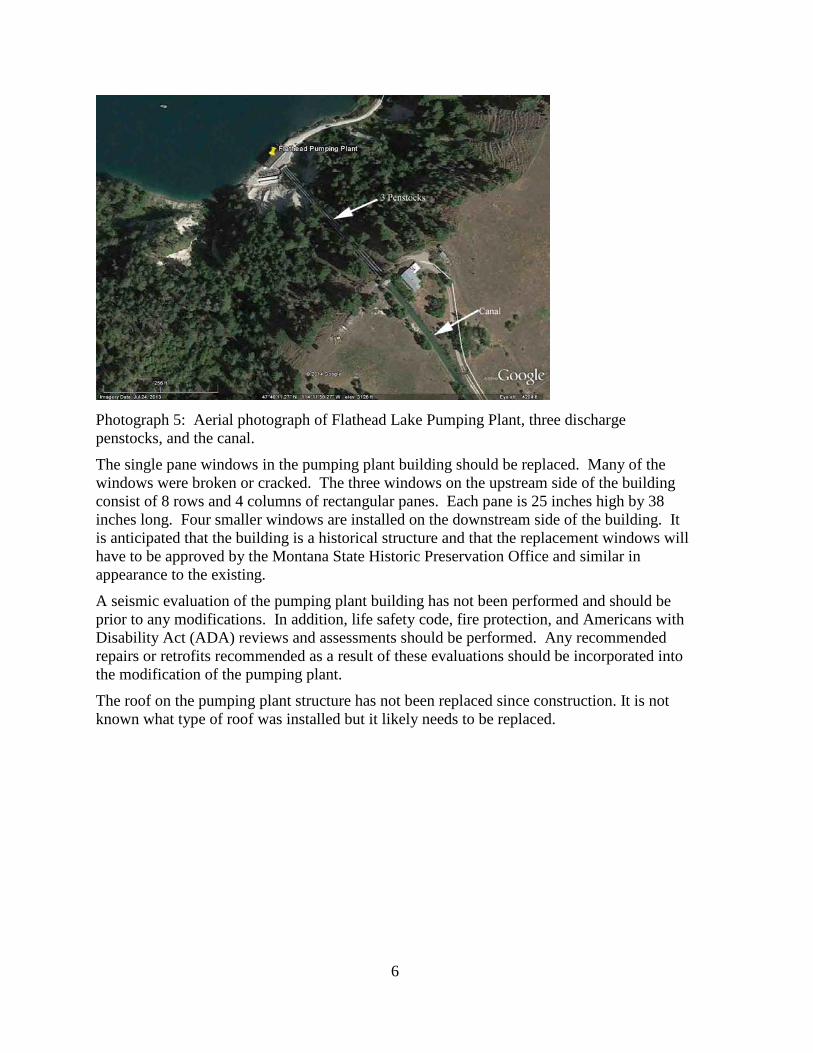
Photograph 23: Flathead Lake Pumping Plant station service battery system.
Plant Personnel Protective Equipment (PPE)
Photograph 24: Looking at missing PPE near the station service batteries.
Synchronous Motor Excitation System
The synchronous motor excitation system (Multilin) appears to be dated from the 1990s and is relatively new and in good condition. Note: If recommendations are followed to install VFD and induction motors, then the excitation system is no longer required.
The station service battery system is located in one of the lower galleries. While the batteries and battery charger appear relatively new, significant corrosion is present on the battery terminals, which are a maintenance issue. If recommendations are followed to install variable frequency drives and induction motors, then the battery system is no longer required thus eliminating battery maintenance. If the batteries are retained, then an exhaust fan and enclosure needs to be installed to vent potentially hazardous hydrogen gas released by the batteries.
The plant has no PPE near the station service batteries. Required PPE includes eye wash stations, protective aprons, gloves, and face shields. The eye wash bottles had been removed from the holder. Note: If recommendations are followed to install variable frequency drives and induction motors, then the battery system is no longer required eliminating the requirement for PPE at this location.

19
Photograph 25: Flathead Lake Pumping Plant synchronous motor excitation system (Multilin).
Photograph 26: Inside of Multilin excitation control.
20
Mechanical Systems
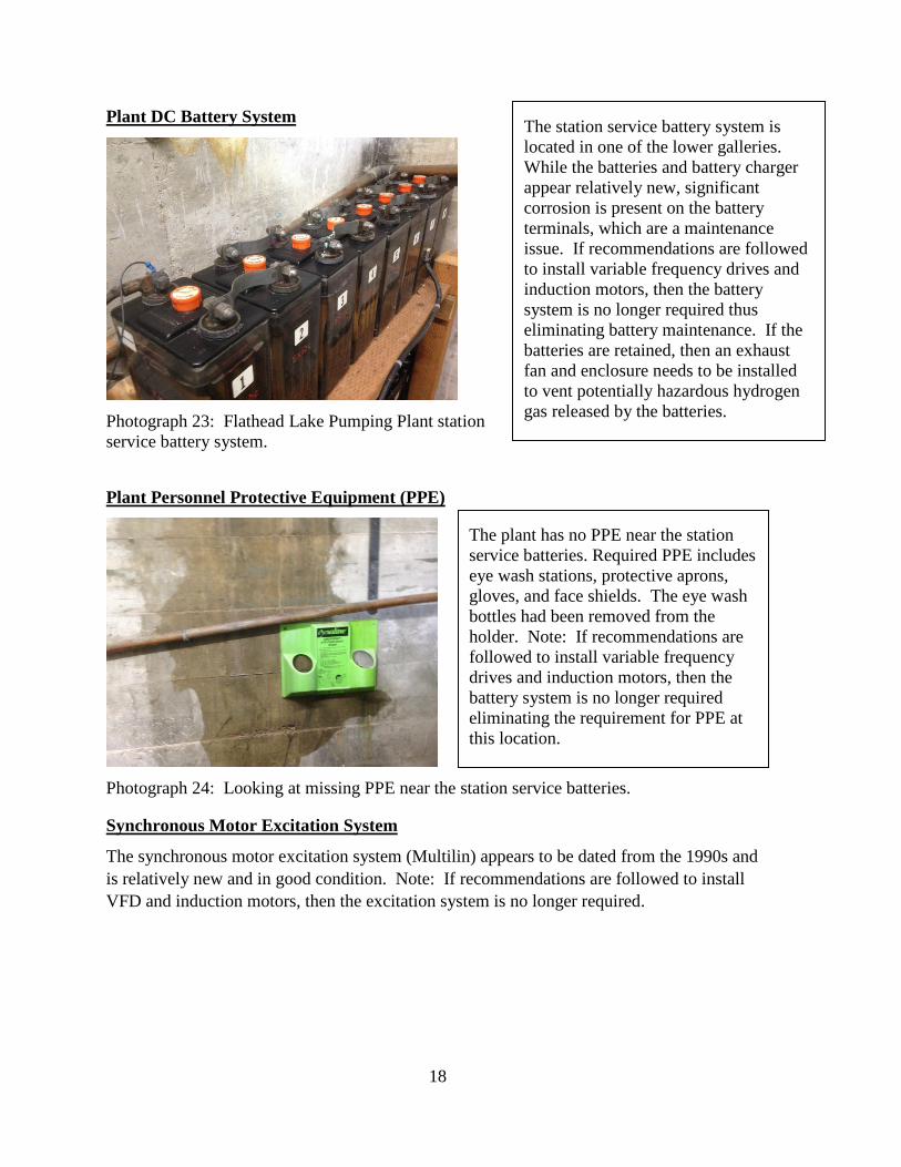
Photograph 27: Pump 3 Nameplate.
Pumps Water is lifted up to the canal system using three Worthington pumps with the install metrics as seen above on the name plate picture. Cavitation in rough zones is significant and the severity could be a result of impeller runners in disrepair. A total rehabilitation of all three runners is needed if not replaced with new runners. Bearings on the pump and bearings up to the motor need rehabilitated. Cracks on pump mounts need to be investigated and repaired. They may have been a result of units being out of alignment in the past. As each unit is rehabilitated, a full alignment needs to be performed. Joints on shafts need to be analyzed and repaired. Plant manager mentioned possible wear and again damage might be a result from units being out of alignment in the past.
Photograph 28: Cracks on Unit 3 pump mounts.
Cracked pump mounts are present on all three units

21
Bearing Oil System
Photograph 29: Bearing Oil Pumps. The bearing oil system seems to be working but the Plant manager stated that there are maintenance issues with the portion of the main line that is under water while Unit 1 is operating. Oil pumps have been repaired, age is an issue, and replacement is needed. Plant Crane
Photograph 30: Flathead Lake Pumping Plant crane. Plant bridge crane was operating while review team was in the plant. It seemed to operate well. Crane testing needs to be performed. Load testing on the crane and inspection of the electronics for the hoist needs to be performed.

22
Crow Creek Pumping Plant Civil Features
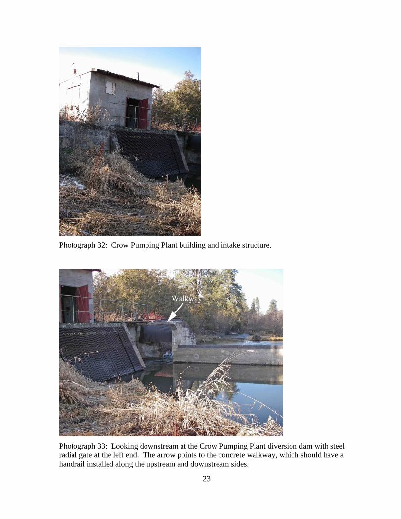
One 20-ft3/s capacity pump is located in a concrete building (approximately 10 feet by 10 feet) with a wooden roof. The roof needs to be replaced. The plant pumps water from Crow Creek, which is impounded by an approximately 5-foot-high concrete diversion dam with a rectangular weir, to an earth-lined canal. An intake structure with a trashrack is located in the pool. The pump intake is screened and frequently plugs with debris which causes the pump to switch off. A steel corrugated metal radial gate is provided in the opening at the left end of the diversion dam to release flows. A narrow reinforced concrete walkway is provided across the top of the radial gate bay. There is no handrail along the sides of the walkway; a handrail should be installed.
The Tribe would like to install a fish passage structure (ladder) at the diversion dam.
Photograph 31: Crow Pumping Plant building.
23
Photograph 32: Crow Pumping Plant building and intake structure.
Photograph 33: Looking downstream at the Crow Pumping Plant diversion dam with steel radial gate at the left end. The arrow points to the concrete walkway, which should have a handrail installed along the upstream and downstream sides.
24
Electrical Features
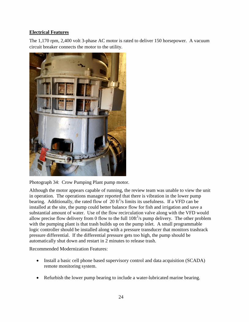
The 1,170 rpm, 2,400 volt 3-phase AC motor is rated to deliver 150 horsepower. A vacuum circuit breaker connects the motor to the utility.
Photograph 34: Crow Pumping Plant pump motor.
Although the motor appears capable of running, the review team was unable to view the unit in operation. The operations manager reported that there is vibration in the lower pump bearing. Additionally, the rated flow of 20 ft3/s limits its usefulness. If a VFD can be installed at the site, the pump could better balance flow for fish and irrigation and save a substantial amount of water. Use of the flow recirculation valve along with the VFD would allow precise flow delivery from 0 flow to the full 10ft3/s pump delivery. The other problem with the pumping plant is that trash builds up on the pump inlet. A small programmable logic controller should be installed along with a pressure transducer that monitors trashrack pressure differential. If the differential pressure gets too high, the pump should be automatically shut down and restart in 2 minutes to release trash.
Recommended Modernization Features:
• Install a basic cell phone based supervisory control and data acquisition (SCADA) remote monitoring system.
• Refurbish the lower pump bearing to include a water-lubricated marine bearing.

25
• Install VFD with vacuum circuit breaker. • Install a small programmable logic controller (PLC) to detect trash rack differential.
Revais Pumping Plant One 10-ft3/s capacity pump is located in a two-story-high concrete stucco building. Except for some bullet holes, the building and roof appeared to be in satisfactory condition. There is an overhead crane in the pumping plant building. Water is pumped from Lower Jocko Canal to an earth-lined canal.
Photograph 35: Reavis Pumping Plant building and intake structure.
Electrical Features The Revais Pumping Plant is capable of operating, with the exception of the pump timer relay wiring . Fixing it requires locating the control system schematic and performing basic electrical diagnostic. Photograph 36 shows wires that have been removed and taped off, which prevents proper operation of the pump timer. Repairs should only cost approximately $200.

26
Wires that have been taped off. Timer function is disabled.
Photograph 36: Wiring to the pump timer relay.

27
Cost Estimate Information The following estimate provides preliminary costs for repair/modification items. There are many unknowns associated with the work items listed below. Detailed analysis and investigations may determine the actual costs are higher than those provided in this report. The preliminary cost estimate data does not include design or contract administration costs and only represent construction costs. Typically, for Reclamation, the design and contract administration costs range from 30 to 35 percent of the total construction costs. In addition, the cost estimate does not include any environmental review, compliance, geological investigations or preliminary study costs which may be required to plan modifications/repairs.
Civil Work Items - Flathead Lake Pumping Plant Estimated Cost
Stabilize landslide1 areas on both sides of the Flathead Lake Pumping Plant penstocks by either alternative A or B:
A. Concrete, reinforced soil (ex. soil nailing), or rock anchors with retaining wall facing retaining wall.
B. Reduce angle of slope to at least 1½ : 1.
$1,399,500
Unknown
Flathead Lake Pumping Plant – Utilize overhead crane to place intake boards.
$70,000
Install safety-compliant walkways on intake structure for the Flathead Lake Pumping Plant.
$17,200
Install trashrack cleaning system on Flathead Lake Pumping Plant intake structure.
$130,000
Install fish screen2 on Flathead Lake Pumping Plant intake to prevent bull trout entrainment.
$750,000
Measure metal thicknesses of the three Flathead Lake Pumping Plant penstocks and evaluate condition.
$15,000
1. Clean and coat exterior of the three Flathead Lake Pumping Plant steel penstocks.
2. Or Replace the 3 steel penstocks
$90,000
unknown
1 This preliminary cost estimate does not include the geological investigations or field exploration program which would be needed to design the slope stability system or structure. These costs are anticipated to cost hundreds of thousands of dollars or more. 2 An evaluation to determine the need for fish screen facility needs to be performed.

28
Civil Work Items - Flathead Lake Pumping Plant Estimated Cost
Replace the windows in the Flathead Lake Pumping Plant building.
$63,000
Replace the roof on the Flathead Lake Pumping Plant building. $31,500
Replace the heaters in the Flathead Lake Pumping Plant. $20,000
Total Civil Costs - Flathead Lake Pumping Plant3 $2,586,200
Electrical Work Items to be Completed – Flathead Lake Pumping Plant
Estimated Cost
Purchase and install three, 3,000-horsepower induction motors, 900 rpm, and 2,400-volt 3-phase. Work includes removing and demolishing existing synchronous motors and interfacing new induction motors to existing motor shafts.
$1,700,000
Remove and demolish existing dry type excitation auto transformers in the pump house.
$45,000
Remove and demolish existing Multilin synchronous motor excitation panels.
$2,100
Remove and demolish existing oil circuit breaker panels. $4,600
Purchase and install three, VFDs for new induction motors. New induction motors should be inverter rated for use with 3,000-horsepower VFDs.
$2,300,000
Purchase and install vacuum circuit breakers with protective relays for each 3,000-horsepower pump.
$70,000
Purchase and install cell phone-based SCADA/alarm system. System to include both local and remote SCADA.
$30,000
Replace cables on station service transformers in substation. $500
Install additional chain link fence on top of substation wall. $3,000
Demolish and remove station circuit breaker panel. $19,000
Purchase and install new 240/120 3-phase station service distribution panel board – 350 amp main breaker with 14.3-phase
$8,000
3 Slope stabilization along Flathead Lake Pumping Plant access road was not included in cost estimate.

29
Electrical Work Items to be Completed – Flathead Lake Pumping Plant
Estimated Cost
breakers.
Prepare engineering design/drawing for above plant modification. $30,000
Total Electrical Costs-Flathead Lake Pumping Plant $4,212,200
Mechanical Work Items to be Completed – Flathead Lake Pumping Plant
Estimated Cost
Inspect pump impellers. Rehabilitate or replace. $425,000
Repair pump mounts. $90,000
Rehabilitate three babbited bearings. Possibly two more if motor is replaced.
$64,000
Install new bearing oil pumps. $39,000
Reroute bearing oil lines. $32,000
Perform full unit alignment. $33,000
Perform crane inspection and load test. $5,000
Total Mechanical Costs-Flathead Lake Pumping Plant $688,000
Total Costs-Flathead Lake Pumping Plant $7,486,400
Civil Work for the Concrete-Lined Discharge Canal from the Flathead Lake Pumping Plant
Extend top of concrete liner by at least 1 foot for 1½ miles of canal.
$315,000
Install perforated pipe drains along seepage areas in cut areas of embankment, assume ½ mile length.
$91,100
Total Costs -Concrete-lined Discharge Canal $406,100

30
Civil Work for the Crow Creek Pumping Plant
Install fish passage (ladder) at the 5-foot-high concrete diversion dam for the Crow Creek Pumping Plant.
$325,000
Replace the roof on the Crow Creek Pumping Plant building. $16,000
Install handrail along the sides of the walkway across the top of the Crow Creek radial gate bay.
$5,000
Total Civil Costs -Crow Creek Pumping Plant $346,000
Electrical Work Items to be Completed – Crow Creek Pumping Plant
Install a basic cell phone-based SCADA remote monitoring system.
$10,000
Refurbish the lower pump bearing to include a water-lubricated marine bearing.
$16,000
Install a 150-horsepower VFD with vacuum circuit breaker. $28,000
Install a small PLC with level transducer to detect trashrack differential.
$2,000
Complete engineering design/drawing for above plant modification.
$12,000
Total Electrical Costs-Crow Creek Pumping Plant $68,000
Total Costs-Crow Creek Pumping Plant $414,000
Electrical Work Items to be Completed – Revais Pumping Plant
Troubleshoot pump control panel and install pump timer relay. $600
GRAND TOTAL-Flathead Lake, Crow Creek, and Revais Pumping Plants
$8,307,100
Cost estimate information provided by Scott Weddle and Robert Ross.

31
Reclamation constructed the Columbia River Pumping Plant (Solicitation No. 1425-3-CC-10-06160) with maximum pumping capacity of 240 ft3/s from June 1993, to March 1995. The total construction cost for the project was $6,635,196. Using an index percentage of 2.03, the total cost is $13,469,448 for the year 2014. The Columbia River Pumping Plant is similar in capacity as the Flathead Lake Pumping Plant. However, the Columbia River Pumping Plant had no slope stability issues, was new construction, and did not include a pumping plant building. The elevation difference between the Columbia River Pumping Plant and the discharge pipe outlet is 286 feet. Replacement or modification costs for the Flathead Lake Pumping Plant may be higher than those for the Columbia River Pumping Plant.
Review Material The following documents were provided for review prior to this site visit.
1. Flathead Lake Pumping Plant Modernization Report dated November 1988 by Tom Sherman of the Bureau of Reclamation, Oroville-Tonasket Construction Office.
2. Draft Design, Estimating and Construction Review Report Flathead Indian Irrigation Project dated September 2012 by the Bureau of Reclamation Technical Service Center, Denver, Colorado

32
Contact List Name Title/Agency Contact Info e-mail
Seth Makepeace Confederated Salish and Kootenai Tribes Natural Resources Department
P.O. Box 278
Pablo, MT 59865
Off 406 675-2700 x 6255
Cell 406 249 -3950
Jeff Harlan Irrigation Engineer
Bureau of Indian Affairs-NWRO
911 NE 11th Ave
Portland, OR 97232
503-231-2278
Peter Plant Supervisory Civil Engineer - Bureau of Indian Affairs
220 Project Drive
Saint Ignatius, MT 59865
406-745-2661 x2
Reed Anderson Bureau of Indian Affairs [email protected]
Stan Jones Hydrologist, Reserved Water Rights Compact Commission, State of Montana
406-444-1270 [email protected]
Kevin Smith Montana State Department of Natural Resources State Water Projects Bureau Chief
PO Box 201601
Helena, MT 59620-1601
406-444-2932
Sonja Norton Civil Engineer
Pacific Northwest Regional Office, Bureau of Reclamation
1150 N. Curtis Road, Suite 100 Boise ID 83706
208-378-5334
Jeffery Garner Mechanical Engineer Pacific Northwest Regional Office, Bureau of Reclamation
1150 N. Curtis Road, Suite 100 Boise ID 83706
208-378-5136
Bob Ross Electrical Engineer Pacific Northwest Regional Office, Bureau of Reclamation
1150 N. Curtis Road, Suite 100 Boise ID 83706
208-378-5332