fabrication of vertical array cnts/polyaniline composite
TRANSCRIPT

NANO EXPRESS Open Access
Fabrication of Vertical Array CNTs/Polyaniline Composite Membranes byMicrowave-Assisted In Situ PolymerizationJie Ding1,2, Xiaoyan Li1*, Xia Wang1*, Jinrui Zhang1, Dengguang Yu1 and Biwei Qiu1
Abstract
A vertical array carbon nanotubes (VACNTs)/polyaniline (PANi) composite membrane was prepared by microwave-assisted in situ polymerization. With microwave assistance, the morphology of PANi revealed a smaller diameterand denser connection. Meanwhile, thermogravimetric analysis showed improved thermal stability of microwave-assisted PANi for higher molecular weight. Focused ion beam thinning method was used to cut the VACNTs/PANimembrane into dozen-nanometer thin strips along the cross-sectional direction, and transmission electronmicroscopy observation showed seamless deposition of PANi between VACNT gaps, without damaging the verticalstatus of CNTs. Meanwhile, stronger conjugate interaction between the quinoid ring of PANi and VACNTs of thecomposite membrane were prompted by microwave-assisted in situ polymerization. By using nanoindentationtechnology, the VACNTs/PANi composite membrane showed exponential increasing of modulus and hardness.Meanwhile, the elasticity was also improved, which was proved by the calculated plastic index. The results canprovide helpful guidance for seamlessly infiltrating matrix into CNT array and also demonstrate the importance ofstructural hierarchy for getting proper behavior of nanostructures.
Keywords: Vertical array carbon nanotubes, Polyaniline, Composite, Microwave assisted
BackgroundCarbon nanotubes (CNTs) [1], with graphene composedof carbon atoms curling to a hollow tubular structure,possess an ultra-high aspect ratio, atomically smoothnanoscale pores for gas transport [2, 3], high mechanicalstrength [4], and unique electronic properties [5–7].Vertical array CNT (VACNT) membranes have foundmany promising applications such as being supercapaci-tors [8], being compliant thermal interface materials [9],in selective gas transport [10], and being reinforcementsin composites for enhanced thermal and mechanicalproperties [11].Infiltrating a matrix material into a large-surface-area
VACNT membrane has attracted great attention forobtaining a novel composite membrane with synergicproperties and improved performances. Several routes,such as chemical vapor deposition (CVD) [12] and spin
coating, can be used to deposit a matrix into the spacebetween vertically aligned and dense carbon-packedCNTs. Hinds et al. [13] grew well-aligned multi-walledcarbon nanotubes (MWCNTs) via CVD; then, a 50 wt%solution of polystyrene and toluene was spin-coated overthe surface. However, spin coating may destroy CNT ar-rays because of its centrifugal force. Holt et al. [14] pre-sented an approach for depositing silicon nitride into aMWCNT array via a low-pressure CVD method; then,the tubes were etched to prepare a seamless compositemembrane. This method could successfully avoiddestroying CNT arrays; however, silicon nitride was toobrittle which limited the mechanical properties of themembrane. Miserendino [15] and Zhang [16] filled inthe gaps of MWCNTs with parylene matrix via CVDand found that parylene could fully pad CNT gaps.Polymer materials exhibit good chemical stability andbiocompatibility, easily filling implement, while choos-ing the appropriate polymer into VACNTs is a con-siderable challenge.
* Correspondence: [email protected]; [email protected] of Material Science and Engineering, University of Shanghai forScience and Technology, Shanghai 200093, ChinaFull list of author information is available at the end of the article
© 2015 Ding et al. Open Access This article is distributed under the terms of the Creative Commons Attribution 4.0International License (http://creativecommons.org/licenses/by/4.0/), which permits unrestricted use, distribution, andreproduction in any medium, provided you give appropriate credit to the original author(s) and the source, provide a link tothe Creative Commons license, and indicate if changes were made.
Ding et al. Nanoscale Research Letters (2015) 10:493 DOI 10.1186/s11671-015-1201-z

Polyaniline (PANi) is a widely studied low-cost electric-ally conducting polymer that exhibits facile synthesis andenvironmental stability [17, 18]. Over the last decades, thechemical synthesis approach has been used to obtain awide variety of PANi with different morphologies andproperties. Ramana [19] prepared a PANi-coated CNTcomposite thin film via an in situ rapid mixing chemicaloxidative polymerization method. Polysulfone compositemembranes created with PANi and functionalized multi-walled CNTs were synthesized using a non-solvent/solv-ent-induced phase separation technique in our researchgroup [20]. In addition, MWCNTs/PANi composite mem-branes were successfully fabricated by filtration andthe flash welding method in our previous work [21].PANi can be synthesized through different approachesto obtain composites with other materials, such as insitu polymerization [22–25], electrochemical processes[26], microemulsion polymerization [27], and inter-facial polymerization [28]. As a novel energy, micro-wave can quickly absorb electromagnetic energy andgenerate rapid thermal effects through molecular di-pole interaction [29]. Microwave-assisted synthesiscan be an effective strategy to control the structureand morphology of a polymer. A PANi nanofiber-coated graphite electrode was successfully fabricatedby microwave-assisted chemical vapor-induced in situpolymerization, with mixed structures of emeraldinebase and fully oxidized form [30].In this study, PANi was deposited seamlessly into the
space between VACNTs by microwave-assisted in situpolymerization. The structure and thermal stability of PANiwere characterized by Fourier transform infrared (FTIR)spectroscopy and thermogravimetric analysis (TGA), re-spectively. Scanning electron microscopy (SEM) and trans-mission electron microscopy (TEM) were used to observethe morphology of PANi and VACNTs/PANi compositemembrane. The structure and interaction of PANi andVACNTs were further explained by FTIR and Raman spec-troscopy. In addition, the nanoscale mechanical propertiesof the VACNTs/PANi membrane were discussed accordingto the nanoindention measurement. The results of the in-vestigation revealed that microwave could be an effectiveway for in situ polymerization and impregnation of PANibetween the VACNT nanotube gaps.
MethodsMaterialsThe VACNTs (MWNT array with 3–10-nm diameter and50-μm length, 98 wt%) were purchased from Chengdu Or-ganic Chemical Co., Ltd., Chinese Academy of Sciences(Chengdu, China). Aniline (ANi) as the monomer, ammo-nium persulfate (APS) as the catalyst, and hydrochloricacid (HCl) (AR grade) were purchased from SinopharmChemical Reagent Co., Ltd. (Shanghai, China).
Synthetic ProceduresPANi was prepared via the chemical oxidization of anil-ine with APS. Appropriate amounts of aniline (6 mmol)and APS (1.5 mmol) were dissolved in 1 vol% HCl(20 ml) solution separately (the volume ratio of anilinewas about 5 %). The proper proportion of aniline andAPS was chosen as 4:1 based on previous experiments,according to the denser and uniform morphology. Thecommercial VACNTs (1 cm × 1 cm) were placed verti-cally in precursor aniline solution for 1 h to let anilineabsorb on the wall of VACNTs. APS solution was slowlyadded to the above mixture while stirring. The glass bea-ker that contained the precursor solution and the VACNTsubstrate was placed in a water bath, then they were putin the center of a microwave oven (MCR-3, Gongyi YuhuaInstrument Co., Ltd., China), and the microwave oven wasset with a temperature mode of 50 °C and radiation timeof 15 min. The procedure was repeated for eight times,and the total microwave irradiation time was 120 min, theschematic of the fabrication process was shown in Fig. 1.Afterwards, the prepared VACNTs/PANi membrane waswashed with water and then freeze-dried. Meanwhile, thepowder of the suspension was also collected by filtrationfor characterizations.To observe surface morphology easily, we prepared
PANi on a cellulose membrane using the same synthesisprocess, and the product was coded as PANi-MW (pow-der or film, depending on the ways of sample collection).In addition, PANi polymerized by chemical oxidation atroom temperature without microwave irradiation wassynthesized for comparison, and the product was alsocoded as PANi (powder or film).
CharacterizationsThe structures of PANi and VACNTs/PANi compositewere characterized by FTIR (Spectrum 100, PerkinElmerCo., Ltd., USA) and Raman (LabRam-1B, Horiba JobinYvon Co., Ltd., USA, laser 532 nm) spectroscopy, re-spectively. Thermal stability was characterized by TGA(Pyris 1, PerkinElmer Co., Ltd., USA) in nitrogen atmos-phere with a 10 °C/min heating rate from 50 to 800 °C.The molecules of PANi were measured via gel
b) c) PANiANia)
Fig. 1 Schematic of the fabrication process. a Monomer anilineimmersed into VACNT gaps. b Microwave irradiation. c VACNTs/PANi composite
Ding et al. Nanoscale Research Letters (2015) 10:493 Page 2 of 9

permeation chromatography (GPC 50, Waters Co., Ltd.,USA) and dissolved in N,N-dimethylformamide. Morph-ology characterizations were imaged using SEM (QuantaFEG450, FEI Co., Ltd., USA) and TEM (Tecnai G2 20TWIN, FEI Co., Ltd., USA). Focused ion beam (FIB, Hel-ios Nanolab 600, FEI Co., Ltd., USA) was used to pre-pare the samples with a thickness of approximately70 nm for TEM observation. Nanoindentation (AgilentNano G200) was performed to investigate the nanome-chanical properties of the samples.
Results and DiscussionFTIR Spectroscopy of PANiThe FTIR spectra of the PANi samples obtained underdifferent synthesis conditions are shown in Fig. 2. PANiexhibited typical characteristic bands at 1590 and1502 cm−1, attributed to the quinoid and benzenoidstructure, respectively. The spectra of PANi-MW wereroughly the same as those of PANi, but differed intwo peaks. The quinoid band and benzenoid band re-vealed a red shift from 1590 and 1502 cm−1 to 1565and 1483 cm−1, respectively, which indicated thatmicrowave irradiation could enhance the conjugated effectfor PANi [31]. Moreover, the band at 1384 cm−1 disap-peared for the electron clouds were shared in N atoms in-stead of “pocketed” to form conjugated systems viamicrowave-assisted method, and the conjugation systemswere further enhanced.
Raman Spectroscopy of PANiRaman spectra obtained from the samples are shownin Fig. 3. PANi were identified with typical peaks of1635 cm−1 (C-C benzenoid), 1592 cm−1 (C=C quinoid),1509 cm−1 (C=N quinoid), 1403 cm−1 (Ar-N benzenoid),1323 cm−1 (C-N benzenoid), 1174 cm−1 (C-H), and576 cm−1 (in-plane benzenoid ring deformation). Withmicrowave assistance, the characteristic band of PANi-MW showed to be similar but differed a little. The quinoidrelevant bands showed to be stronger while the benzenoidbands showed to be weaker. Meanwhile, C-C (1635 cm−1)
1800 1600 1400 1200 1000 800wavenumber(cm-1)
PANi-MW PANi
1590 1502 1307
1113
824
1565 1483 12951119
816
1384
Fig. 2 FTIR spectra of PANi and PANi-MW
500 1000 1500 2000
1174 13
2314
03
576
1509 15
92
yti sne tnI
Raman Shift(cm-1)
PANi MW PANi
1635
Fig. 3 Raman spectra of PANi and PANi-MW
Ding et al. Nanoscale Research Letters (2015) 10:493 Page 3 of 9

and in-plane benzenoid ring deformation (576 cm−1) disap-peared, indicating that the microwave irradiation providedthe energy for increasing the quinoid fraction.
Surface Morphology of PANiThe surface morphologies of PANi-MW and PANi syn-thesized at room temperature (deposited on a cellulosemembrane) are shown in Fig. 4. The PANi prepared atroom temperature presented nanorod shapes, diametersranging from 300 to 500 nm. PANi-MW morphology re-vealed a smaller diameter and denser connection statesthan that of PANi. PANi-MW was nearly completelycovered with less overgrown granules that resulted fromthe uniform energy reception of microwave radiation. Adense topography of PANi-MW was favorable for seam-lessly filling in the CNT array.
Molecular MeasurementsThe number average molecular mass (Mn) and polydis-persity index (PDI) of PANi and PANi-MW are shownin Table 1. The Mn of PANi-MW was 5.09 × 10⁵, nearlyfive times that of PANi (Mn = 1.08 × 10⁵). Meanwhile,the PDI of PANi-MW was narrower than that of PANi.GPC analysis proved more homogeneous and longerPANi molecular chains can be generated by microwave-assisted in situ polymerization.
TG AnalysisThe TG result of PANi is shown in Fig. 5. The weightloss below 100 °C could be assigned to the loss of theinitial water molecules. Two weight loss stages were
observed after 100 °C. From 100 to 300 °C, weight losscould be mainly attributed to the decomposition ofPANi with low molecular weight. Rapid weight loss oc-curred in the temperature range of 300 to 600 °C, andthe peak decomposition temperature of PANi-MW wasimproved from 439 °C (PANi) to 555 °C, as seen in insetof Fig. 5; in addition, the residuals (at 600 °C) of PANi-MW were increased from 58.3 % (PANi) to 71.2 %. Theimproved thermostability could be attributed to themore conjugated structure of PANi-MW caused bymicrowave irradiation, and the result was consistent withthe GPC analysis for the higher molecular and narrowerPDI of PANi-MW.
SEM of VACNTs/PANi CompositeCompared to the raw VACNTs in Fig. 6a, seamless andcomplete polymer coating is shown in Fig. 6b. Inaddition, the vertical array structure was unaffected bythe microwave-assisted in situ polymerization, exhibitedby the “standing” forest morphology in the side sectionof the VACNTs/PANi composite. As shown in the high-magnification image (Fig. 6c), the diameter of VACNTswas significantly larger, coated uniformly and completelywith rough PANi nanoparticles. Meanwhile, no largevoid or crack was observed on the surface of theVACNTs/PANi composite membrane (Fig. 6d).
TEM of VACNTs/PANi Cross SectionTo further reveal the PANi-occupied state betweenVACNT gaps, the cross section of the VACNTs andVACNTs/PANi composite membrane was analyzed byTEM observation.In this paper, the TEM cross section sample was pre-
pared by FIB method, shown in Fig. 7a. The FIB slicingprocessing is as follows. First, an area (approximately10 μm) was selected, and a protective layer of platinumwas deposited on the surface. Second, three sides of thesample were slotted, and then the bottom was cut,
a b
Fig. 4 SEM images of a PANi and b PANi-MW on a cellulose membrane
Table 1 GPC analysis of PANi and PANi-MW
Sample Mn PDI
PANi 1.08 × 10⁵ 3.64
PANi-MW 5.09 × 10⁵ 1.62
Ding et al. Nanoscale Research Letters (2015) 10:493 Page 4 of 9

followed by cutting off the right side after adhering thesample to the tungsten probe. Third, the sample wasconglutinated to the special copper mesh. Finally, thesample was cut to a desired thickness (approximately70 nm) by FIB.
As shown in Fig. 7b, the cross section of VACNTs wasbroken with loose nanotube distribution. FIB processingmay lead to bundling phenomenon of VACNTs, showinga much bigger diameter. TEM morphology of theVACNTs/PANi cross section (Fig. 7c) showed
100 200 300 400 500 600 70030
40
50
60
70
80
90
100
300 400 500 600
-1.5
-1.0
-0.5
0.0
)%(thgie
w
temperature(
PANi PANi-MW
555
439
)
Fig. 5 TG spectra of PANi and PANi-MW in nitrogen
a b
c d
Fig. 6 SEM images of a raw VACNTs side section, b VACNTs/PANi composite side section, c enlarged PANi-coated CNTs, and d VACNTs/PANi surface
Ding et al. Nanoscale Research Letters (2015) 10:493 Page 5 of 9

continuous PANi distribution between the nanotubegaps, providing good support effect. The bright whitespots in Fig. 7e are carbon nanotube pores, and the mul-tiwall and the surrounding polymer structures could beobserved in Fig. 7f and inset. The TEM images demon-strated that PANi coated VACNTs properly and did notleave any gap and cracks, and the nanotubes kept thevertical state during the FIB slicing process. The averagegap width between the nanotubes was estimated to be30 ± 5 nm, which could be derived from the histogramof the gap width between the nanotubes (counted from324 individual CNTs) in Fig. 7d.
Structure of VACNTs/PANi CompositeFTIR and Raman spectra of VACNTs, PANi-MW, andthe VACNTs/PANi composite are shown in Fig. 8 toconfirm the structures. In Fig. 8a, the characteristicbands of 1640 and 1380 cm−1 indicated the C=C ofVACNTs. In the VACNTs/PANi composite, it was no-ticed that there was a single band of 1660 cm−1 for mer-gence of the quinoid band (1565 cm−1 in PANi-MW)and C=C band (1640 cm−1 in VACNTs). Meanwhile,with the presence of VACNTs, the PANi structure wasinfluenced with a more red shift of C-N (1295 to1287 cm−1), indicating a strong interaction between
70 nm
1-2 um
b
0 10 20 30 40 50 60 70 800.0
0.1
0.2
0.3
ytilibaborp
gap width(nm)
c
d
e f
Fig. 7 FIB sample preparation and TEM images. a TEM sample prepared by FIB. b TEM images of VACNT cross section. c, e, f TEM images ofVACNTs/PANi composite membrane cross section at different magnifications. d Histogram of gap width between the tubes
Ding et al. Nanoscale Research Letters (2015) 10:493 Page 6 of 9

VACNTs and PANi via π-stacking [32]. Moreover,strengthened quinoid (1423 cm−1) and disappearedN=quinoid=N (1119 cm−1) in the VACNTs/PANi com-posite revealed the conjugate interaction between thequinoid unit of PANi and VACNTs.As for the VACNTs, the characteristic Raman bands
at ~1595 cm−1 (G band) and ~1300 cm−1 (D band)indicated graphitic nature and disorderness pertainingto VACNTs, respectively. The G band to D band in-tensity ratio of approximately 6.32 indicated the highcrystallinity of the MWCNTs. However, in the case ofthe VACNTs/PANi composite, the disappearance ofthe characteristic G band indicated that the VACNTswere coated with PANi, while the vibration peak at1472 cm−1 increased with VACNTs. Meanwhile, there
was a considerable red shift in characteristic bandscorresponding to C=C (from 1595 to 1586 cm−1) andC=N (from 1504 to 1472 cm−1) stretching of quinoid,consistent with the FTIR results. VACNTs wereelectron-rich molecules that form π-π interaction andCH-π interaction, and microwave irradiation offered theenergy for the formation of a charge-transfer complex be-tween the VACNTs and aniline. Aromatic structures, ingeneral, were known to interact strongly with the basalplane of graphitic surface via π-stacking which was due to acharge transfer from the quinoid unit of PANi to VACNTs.
Nanoindentation of VACNTs/PANi CompositeNanoindentations of raw VACNTs, PANi-MW, and theVACNTs/PANi composite were performed to evaluate
1800 1600 1400 1200 1000 800
VACNTs
128714231495
PANi-MW
Wavenumber(cm-1)
13801640
1119129514831565
VACNTs/PANi
1660
500 1000 1500 2000
1504
1586
1472
ytis netnI
Raman Shift(cm-1)
VACNTs/PANiPANi MW
1595
1300
1590
VACNTsa b
Fig. 8 a FTIR and b Raman spectra for VACNTs, PANi-MW, and VACNTs/PANi composite
Fig. 9 Nanoindention of VACNTs/PANi, VACNTs, and PANi-MW
Ding et al. Nanoscale Research Letters (2015) 10:493 Page 7 of 9
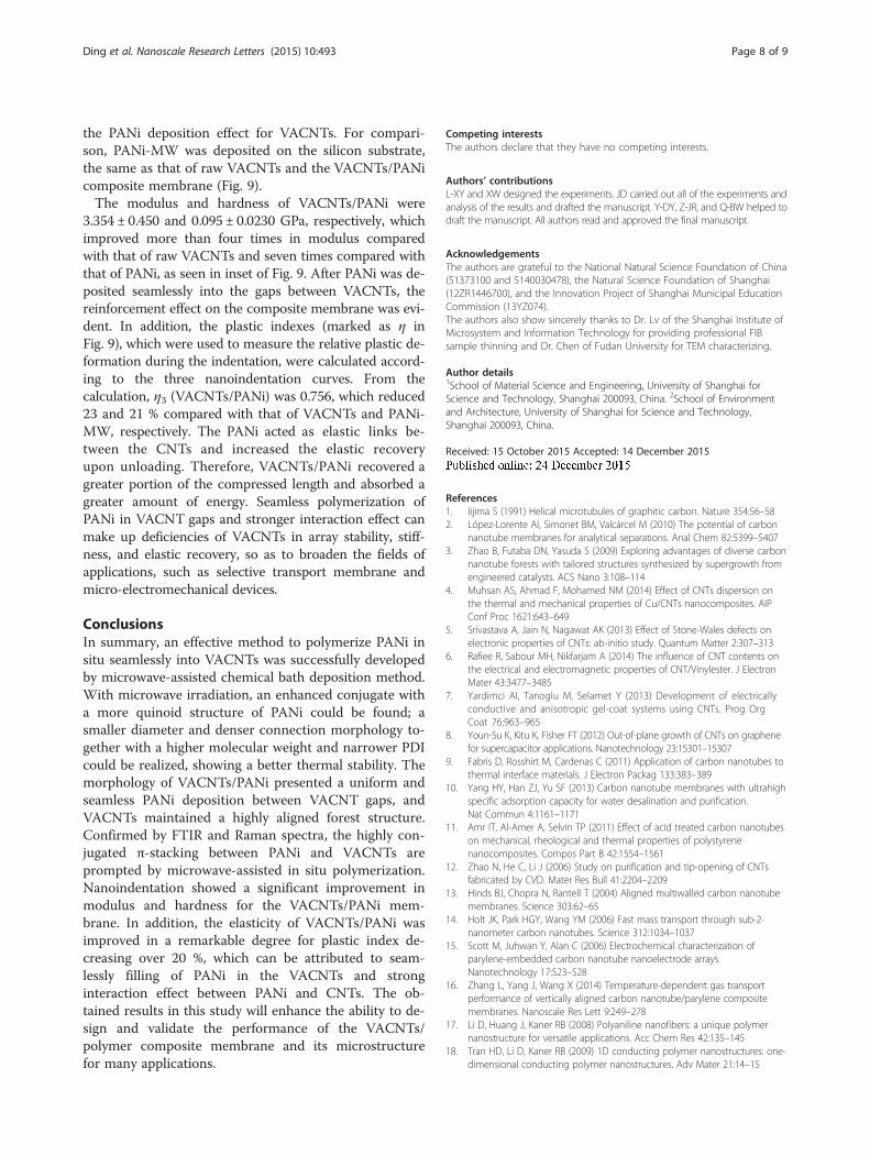
the PANi deposition effect for VACNTs. For compari-son, PANi-MW was deposited on the silicon substrate,the same as that of raw VACNTs and the VACNTs/PANicomposite membrane (Fig. 9).The modulus and hardness of VACNTs/PANi were
3.354 ± 0.450 and 0.095 ± 0.0230 GPa, respectively, whichimproved more than four times in modulus comparedwith that of raw VACNTs and seven times compared withthat of PANi, as seen in inset of Fig. 9. After PANi was de-posited seamlessly into the gaps between VACNTs, thereinforcement effect on the composite membrane was evi-dent. In addition, the plastic indexes (marked as η inFig. 9), which were used to measure the relative plastic de-formation during the indentation, were calculated accord-ing to the three nanoindentation curves. From thecalculation, η3 (VACNTs/PANi) was 0.756, which reduced23 and 21 % compared with that of VACNTs and PANi-MW, respectively. The PANi acted as elastic links be-tween the CNTs and increased the elastic recoveryupon unloading. Therefore, VACNTs/PANi recovered agreater portion of the compressed length and absorbed agreater amount of energy. Seamless polymerization ofPANi in VACNT gaps and stronger interaction effect canmake up deficiencies of VACNTs in array stability, stiff-ness, and elastic recovery, so as to broaden the fields ofapplications, such as selective transport membrane andmicro-electromechanical devices.
ConclusionsIn summary, an effective method to polymerize PANi insitu seamlessly into VACNTs was successfully developedby microwave-assisted chemical bath deposition method.With microwave irradiation, an enhanced conjugate witha more quinoid structure of PANi could be found; asmaller diameter and denser connection morphology to-gether with a higher molecular weight and narrower PDIcould be realized, showing a better thermal stability. Themorphology of VACNTs/PANi presented a uniform andseamless PANi deposition between VACNT gaps, andVACNTs maintained a highly aligned forest structure.Confirmed by FTIR and Raman spectra, the highly con-jugated π-stacking between PANi and VACNTs areprompted by microwave-assisted in situ polymerization.Nanoindentation showed a significant improvement inmodulus and hardness for the VACNTs/PANi mem-brane. In addition, the elasticity of VACNTs/PANi wasimproved in a remarkable degree for plastic index de-creasing over 20 %, which can be attributed to seam-lessly filling of PANi in the VACNTs and stronginteraction effect between PANi and CNTs. The ob-tained results in this study will enhance the ability to de-sign and validate the performance of the VACNTs/polymer composite membrane and its microstructurefor many applications.
Competing interestsThe authors declare that they have no competing interests.
Authors’ contributionsL-XY and XW designed the experiments. JD carried out all of the experiments andanalysis of the results and drafted the manuscript. Y-DY, Z-JR, and Q-BW helped todraft the manuscript. All authors read and approved the final manuscript.
AcknowledgementsThe authors are grateful to the National Natural Science Foundation of China(51373100 and 5140030478), the Natural Science Foundation of Shanghai(12ZR1446700), and the Innovation Project of Shanghai Municipal EducationCommission (13YZ074).The authors also show sincerely thanks to Dr. Lv of the Shanghai Institute ofMicrosystem and Information Technology for providing professional FIBsample thinning and Dr. Chen of Fudan University for TEM characterizing.
Author details1School of Material Science and Engineering, University of Shanghai forScience and Technology, Shanghai 200093, China. 2School of Environmentand Architecture, University of Shanghai for Science and Technology,Shanghai 200093, China.
Received: 15 October 2015 Accepted: 14 December 2015
References1. Iijima S (1991) Helical microtubules of graphitic carbon. Nature 354:56–582. López-Lorente AI, Simonet BM, Valcárcel M (2010) The potential of carbon
nanotube membranes for analytical separations. Anal Chem 82:5399–54073. Zhao B, Futaba DN, Yasuda S (2009) Exploring advantages of diverse carbon
nanotube forests with tailored structures synthesized by supergrowth fromengineered catalysts. ACS Nano 3:108–114
4. Muhsan AS, Ahmad F, Mohamed NM (2014) Effect of CNTs dispersion onthe thermal and mechanical properties of Cu/CNTs nanocomposites. AIPConf Proc 1621:643–649
5. Srivastava A, Jain N, Nagawat AK (2013) Effect of Stone-Wales defects onelectronic properties of CNTs: ab-initio study. Quantum Matter 2:307–313
6. Rafiee R, Sabour MH, Nikfarjam A (2014) The influence of CNT contents onthe electrical and electromagnetic properties of CNT/Vinylester. J ElectronMater 43:3477–3485
7. Yardimci AI, Tanoglu M, Selamet Y (2013) Development of electricallyconductive and anisotropic gel-coat systems using CNTs. Prog OrgCoat 76:963–965
8. Youn-Su K, Kitu K, Fisher FT (2012) Out-of-plane growth of CNTs on graphenefor supercapacitor applications. Nanotechnology 23:15301–15307
9. Fabris D, Rosshirt M, Cardenas C (2011) Application of carbon nanotubes tothermal interface materials. J Electron Packag 133:383–389
10. Yang HY, Han ZJ, Yu SF (2013) Carbon nanotube membranes with ultrahighspecific adsorption capacity for water desalination and purification.Nat Commun 4:1161–1171
11. Amr IT, Al-Amer A, Selvin TP (2011) Effect of acid treated carbon nanotubeson mechanical, rheological and thermal properties of polystyrenenanocomposites. Compos Part B 42:1554–1561
12. Zhao N, He C, Li J (2006) Study on purification and tip-opening of CNTsfabricated by CVD. Mater Res Bull 41:2204–2209
13. Hinds BJ, Chopra N, Rantell T (2004) Aligned multiwalled carbon nanotubemembranes. Science 303:62–65
14. Holt JK, Park HGY, Wang YM (2006) Fast mass transport through sub-2-nanometer carbon nanotubes. Science 312:1034–1037
15. Scott M, Juhwan Y, Alan C (2006) Electrochemical characterization ofparylene-embedded carbon nanotube nanoelectrode arrays.Nanotechnology 17:S23–S28
16. Zhang L, Yang J, Wang X (2014) Temperature-dependent gas transportperformance of vertically aligned carbon nanotube/parylene compositemembranes. Nanoscale Res Lett 9:249–278
17. Li D, Huang J, Kaner RB (2008) Polyaniline nanofibers: a unique polymernanostructure for versatile applications. Acc Chem Res 42:135–145
18. Tran HD, Li D, Kaner RB (2009) 1D conducting polymer nanostructures: one-dimensional conducting polymer nanostructures. Adv Mater 21:14–15
Ding et al. Nanoscale Research Letters (2015) 10:493 Page 8 of 9

19. Ramana GV, Padya B, Srikanth VVSS (2014) Rapid mixing chemical oxidativepolymerization: an easy route to prepare PANI coated small-diameter CNTs/PANI nanofibres composite thin film. Bull Mater Sci 37:585–588
20. Liao YZ, Yu DG, Wang X (2013) Carbon nanotube-templated polyanilinenanofibers: synthesis, flash welding and ultrafiltration membranes.Nanoscale 5:3856–3862
21. Cai SS, Li XY, Wang X (2014) Preparation of MWNTs/polyaniline compositemembranes by filtration and flash welding method. Indian J Eng Mater Sci21:567–572
22. Wei Z, Wan M, Lin T (2003) Polyaniline nanotubes doped with sulfonatedcarbon nanotubes made via a self‐assembly process. Adv Mater 15:136–139
23. Small WR, Masdarolomoor F, Wallace GG (2007) Inkjet deposition andcharacterization of transparent conducting electroactive polyanilinecomposite films with a high carbon nanotube loading fraction. J MaterChem 17:4359–4361
24. Ginic-Markovic M, Matisons JG, Cervini R (2006) Synthesis of new polyaniline/nanotube composites using ultrasonically initiated emulsion polymerization.Chem Mater 18(26):6258–6265
25. Salvatierra RV, Oliveira MM, Zarbin AJG (2010) One-pot synthesis andprocessing of transparent, conducting, and freestanding carbonnanotubes/polyaniline composite films. Chem Mater 22:5222–5234
26. Bhadra S, Singha NK, Khastgir D (2007) Electrochemical synthesis of polyanilineand its comparison with chemically synthesized polyaniline. J Appl Polym Sci104:1900–1904
27. Prasannan A, Somanathan N, Hong PD (2009) Studies on polyaniline–polypyrrole copolymer micro emulsions. Mater Chem Phys 116:406–414
28. Abdolahi A, Hamzah E, Ibrahim Z (2012) Synthesis of uniform polyanilinenanofibers through interfacial polymerization. Materials 5:1487–1494
29. Wiesbrock F, Hoogenboom R, Schubert US (2004) Microwave-assisted polymersynthesis: state-of-the-art and future perspectives. Macromol Rapid Commun25:1739–1764
30. Li XQ, Yang L, Lei Y, Gu L, Xiao D (2014) Microwave-assisted chemical-vapor-induced in situ polymerization of polyaniline nanofibers on graphite electrodefor high-performance supercapacitor. ACS Appl Mater Interfaces 6:19978–19989
31. Gizdavic-Nikolaidis MR, Jevremovic MM, Allison MC (2014) Self-assembly ofnanostructures obtained in a microwave-assisted oxidative polymerizationof aniline. Express Polym Lett 8:745–755
32. Mi HY, Zhang XG, An SY, Ye XG, Yang SD (2007) Microwave-assisted synthesisand electrochemical capacitance of polyaniline/multi-wall carbon nanotubescomposite. Electrochem Commun 9:2859–2862
Submit your manuscript to a journal and benefi t from:
7 Convenient online submission
7 Rigorous peer review
7 Immediate publication on acceptance
7 Open access: articles freely available online
7 High visibility within the fi eld
7 Retaining the copyright to your article
Submit your next manuscript at 7 springeropen.com
Ding et al. Nanoscale Research Letters (2015) 10:493 Page 9 of 9