fabrication of solid polymer electrolyte-based electrodes for voltammetry in the absence of...
TRANSCRIPT
2380 Anel. Chem. lB91, 63, 2380-2383
(14) Boone, C. W.; Kelloff, 0. J.; Malone, W. E. Cancer Res. 1990, 50,
(15) Wlndhorst D. E.; Nigra, T. J . Am. Aced. Demretd. 1982, 6 ,
(16) Kochlar, D. M.; Penner, J. D.; Tellone, C. Teratog., Carclnog., Mote- p n . 1984, 4 , 377.
(17) Orfanos, C. E.; Ehlert, R.; Gollnick, H. Dnrgs 1987, 34, 459-503. (18) Motto, M. G.; Facchine, K. L.; Hamburg, P. F.; Bwlnsky, D. J.; Dunphy,
R.; Oyler, A. R.; Cotter, M. L. J . chrometogr. 1989, 481, 255-262. (19) YU. M.; DOvlChl, N. J. Appl. S ~ ~ C ~ ~ O S C . 1989, 43, 196-201. (20) CRC Henolbodc ot Chemistry and phvsics, 55th ed.; CRC Press: Boca
Raton, FL, 1974; p D-129. (21) Ewlng, A. G.; Walllngford, R. A.; Oleftowicz, T. M. Anal. Chem. 1989,
(22) Adamson, A. W. Fhydcel Chemistry of Surfaces, 5th ed.; Wlley Inter-
science: New York, 1990; pp 218-219. (23) Fujiwara, S.; Honda. S. Anal. Chem. 1987, 59, 487-490. 2-9.
Richard R. Chadwick* Jeff C. Hsieh
675-682.
Allergan Optical 2525 Dupont Drive Irvine, California 92715
RECEIVED for review February 12,1991. Revised manuscript received July 3, 1991. Accepted July 10, 1991.
6 1 , 292A-303A.
Fabrication of Solid Polymer Electrolyte-Based Electrodes for Voltammetry in the Absence of Supporting Electrolyte
Sir: Many approaches have been used to carry out vol- tammetry in nonconducting solutions, including microelec- trodes, permeable membrane electrodes, and electrodes in- corporating solid polymer electrolytes (SPES). These methods have been reviewed recently (I, 2). The SPEbased electrodes (e.g. see refs 1-6) have been fabricated to date by chemically or physically embedding an electrode material into a pre- formed ion-exchange membrane (typically Nafion, E. I. du Pont de Nemours & Co.). These electrodes, however, require a somewhat elaborate cell assembly and are restricted to a microelectode array configuration.
We describe here an alternate approach for fabricating an SPEbased electrode. The key feature of this approach is that the SPE is polymerized around a suitable electrode rather than starting with a preformed polymer. Some preliminary results on the fabrication and characteristics of the polymer chosen (p-hydroxybenzenesulfonic acid/formaldehyde) and the electrochemical performance of a SPE/Pt composite are discussed.
EXPERIMENTAL SECTION
Chemicals. All chemicals were reagent grade unless otherwise specified. Sodium p-hydroxybenzenesulfonate (98%, Aldrich), formaldehyde (37% aqueous solution, Fisher), sulfuric acid (Mallinkrodt) , hydroquinone (Sargent- Welch), 2-propanol (HPLC grade, Mallinkrodt), ethanol (HPLC grade, Aldrich), ethyl acetate (HPLC grade, Burdick & Jackson), hexane (HPLC grade, Aldrich), acetonitrile (Mallinkrodt), and potassium chloride (Mallinkrodt) were used as received. Reagent grade methanol (Sargent-Welch) was further purified following the procedure of Wolfhagen and Soltese (7). Quinone (Eastman) was purified by double-subli- mation just prior to use. The methanol stabilizer in the form- aldehyde was removed by using a Buchi rotovapor connected to an aspirator. Distilled water was further purified by passing it through a Barnstead Nanopure I1 system.
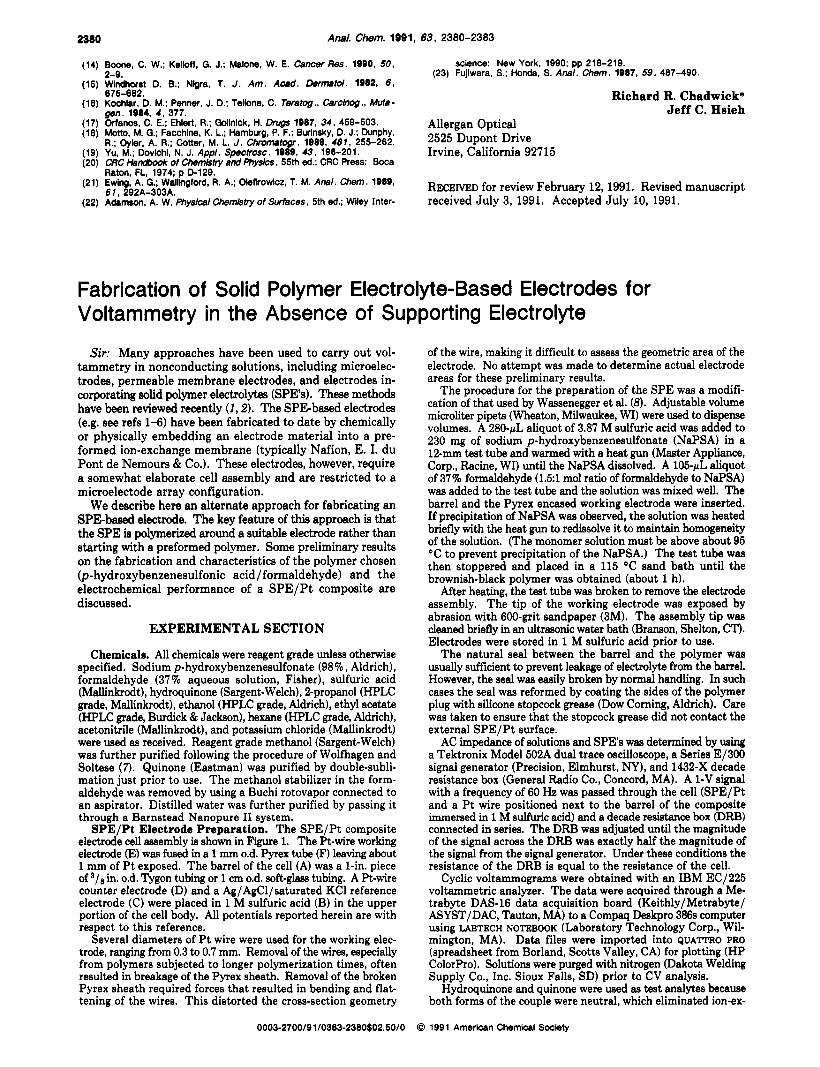
SPE/Pt Electrode Preparation. The SPE/Pt composite electrode cell assembly is shown in Figure 1. The Pt-wire working electrode (E) was fused in a 1 mm 0.d. Pyrex tube (F) leaving about 1 mm of Pt exposed. The barrel of the cell (A) was a 1-in. piece of 3/e in. 0.d. Tygon tubing or 1 cm 0.d. soft-glass tubing. A Pt-wire counter electrode (D) and a Ag/AgCl/saturated KCl reference electrode (C) were placed in 1 M sulfuric acid (B) in the upper portion of the cell body. All potentials reported herein are with respect to this reference.
Several diameters of Pt wire were used for the working elec- trode, ranging from 0.3 to 0.7 mm. Removal of the wires, especially from polymers subjected to longer polymerization times, often resulted in breakage of the Pyrex sheath. Removal of the broken Pyrex sheath required forces that resulted in bending and flat- tening of the wires. This distorted the cross-section geometry
of the wire, making it difficult to assess the geometric area of the electrode. No attempt was made to determine actual electrode areas for these preliminary results.
The procedure for the preparation of the SPE was a modifi- cation of that used by Wassenegger et al. (8). Adjustable volume microliter pipets (Wheaton, Milwaukee, WI) were used to dispense volumes. A 280-pL aliquot of 3.87 M sulfuric acid was added to 230 mg of sodium p-hydroxybenzenesulfonate (NaPSA) in a 12-mm test tube and warmed with a heat gun (Master Appliance, Corp., Racine, WI) until the NaPSA dissolved. A 105-pL aliquot of 37% formaldehyde (1.51 mol ratio of formaldehyde to NaPSA) was added to the test tube and the solution was mixed well. The barrel and the Pyrex encased working electrode were inserted. If precipitation of NaPSA was observed, the solution WBS heated briefly with the heat gun to redissolve it to maintain homogeneity of the solution. (The monomer solution must be above about 95 "C to prevent precipitation of the NaPSA.) The test tube was then stoppered and placed in a 115 "C sand bath until the brownish-black polymer was obtained (about 1 h).
After heating, the teat tube was broken to remove the electrode assembly. The tip of the working electrode was exposed by abrasion with 600-grit sandpaper (3M). The assembly tip was cleaned briefly in an ultrasonic water bath (Branson, Shelton, CT). Electrodes were stored in 1 M sulfuric acid prior to use.
The natural seal between the barrel and the polymer was usually sufficient to prevent leakage of electrolyte from the barrel. However, the seal was easily broken by normal handling. In such cases the seal was reformed by coating the sides of the polymer plug with silicone stopcock grease (Dow Corning, Aldrich). Care was taken to ensure that the stopcock grease did not contact the external SPE/Pt surface.
AC impedance of solutions and SPES was determined by using a Tektronix Model 502A dual trace oscilloscope, a Series El300 signai generator (Precision, Elmhurst, NY), and 1432-X decade resistance box (General Radio Co., Concord, MA). A 1-V signal with a frequency of 60 Hz was passed through the cell (SPE/Pt and a Pt wire positioned next to the barrel of the composite immersed in 1 M sulfuric acid) and a decade resistance box @RBI connected in series. The DRB was adjusted until the magnitude of the signal across the DRB was exactly half the magnitude of the signal from the signal generator. Under these conditions the resistance of the DRB is equal to the resistance of the cell.
Cyclic voltammograms were obtained with an IBM EC/225 voltammetric analyzer. The data were acquired through a Me- trabyte DAS-16 data acquisition board (Keithly/Metrabyte/ ASYST/DAC, Tauton, MA) to a Compaq Deskpro 386s computer using LABTECH NOTEBOOK (Laboratory Technology Corp., Wil- mington, MA). Data files were imported into QUATTRO PRO (spreadsheet from Borland, Scotts Valley, CA) for plotting (HP ColorPro). Solutions were purged with nitrogen (Dakota Welding Supply Co., Inc. Sioux Falls, SD) prior to CV analysis.
Hydroquinone and quinone were used as test analytes because both forms of the couple were neutral, which eliminated ion-ex-
0003-2700/91/0363-2380$02.50/0 0 199 1 Amerlcan Chemlcal Society
ANALYTICAL CHEMISTRY, VOL. 63, NO. 20, OCTOBER 15, 1991 2381
--
- A
4 1 B
4 C
4 D - f
LcIG Figure 1. Polymer/Pt composite electrode assembly: (A) barrel, (B) electrolyte solution, (C) reference electrode, (D) Pt counter electrode, (E) Pt working electrode, (F) Pyrex shroud for working electrode, (G) SPE.
change effects, and because at least one species of the couple was soluble in each solvent used. The more soluble form was used in each solvent.
Infrared spectra were obtained on an IBM Model 38 FTIR.
RESULTS AND DISCUSSION I. Fabrication Observations. In early studies p -
hydroxybenzenesulfonic acid (55% solution, Aldrich) was used to produce the polymer. The sodium salt, NaPSA, was sub- stituted for the p-hydroxybenzenesulfonic acid when it was discovered that the acid contained an unidentified impurity that exhibited electroactivity in the same potential region as hydroquinone. NaPSA did not exhibit the impurity problem.
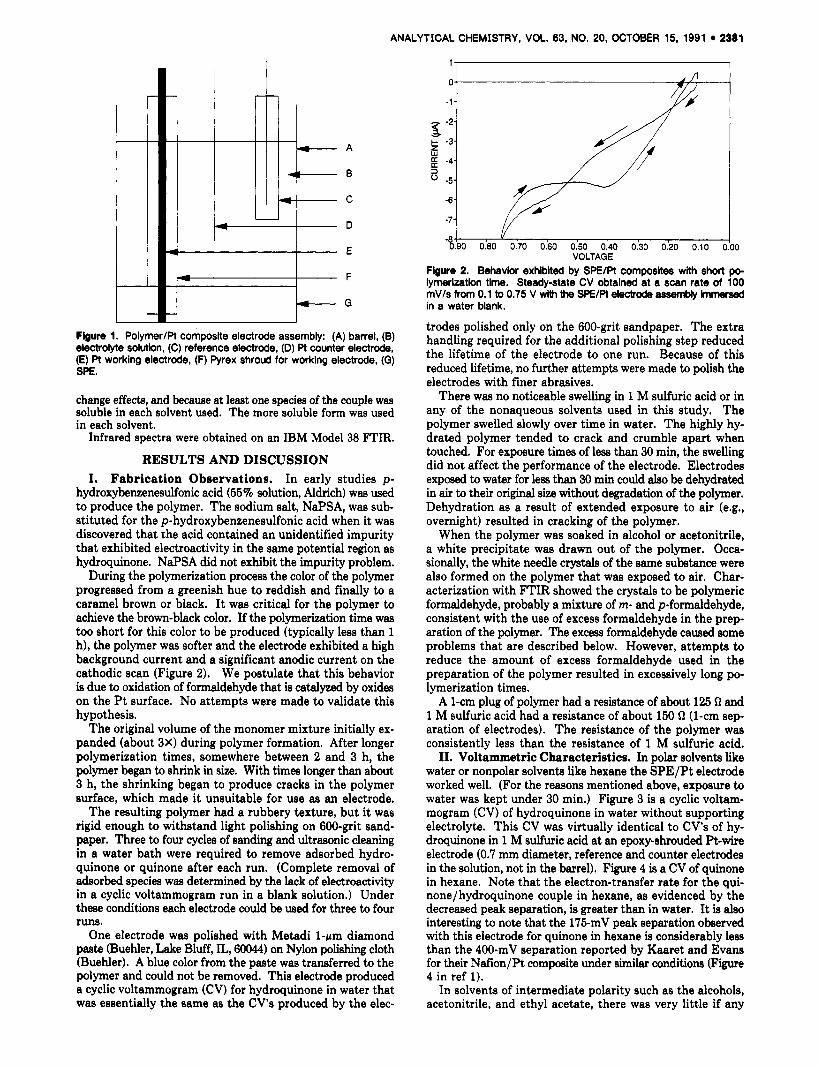
During the polymerization process the color of the polymer progressed from a greenish hue to reddish and finally to a caramel brown or black. I t was critical for the polymer to achieve the brown-black color. If the polymerization time was too short for this color to be produced (typically less than 1 h), the polymer was softer and the electrode exhibited a high background current and a significant anodic current on the cathodic scan (Figure 2). We postulate that this behavior is due to oxidation of formaldehyde that is catalyzed by oxides on the Pt surface. No attempts were made to validate this hypothesis.
The original volume of the monomer mixture initially ex- panded (about 3X) during polymer formation. After longer polymerization times, somewhere between 2 and 3 h, the polymer began to shrink in size. With times longer than about 3 h, the shrinking began to produce cracks in the polymer surface, which made it unsuitable for use as an electrode.
The resulting polymer had a rubbery texture, but it was rigid enough to withstand light polishing on 600-grit sand- paper. Three to four cycles of sanding and ultrasonic cleaning in a water bath were required to remove adsorbed hydro- quinone or quinone after each run. (Complete removal of adsorbed species was determined by the lack of eledroactivity in a cyclic voltammogram run in a blank solution.) Under these conditions each electrode could be used for three to four runs.
One electrode was polished with Metadi 1-rm diamond paste (Buehler, Lake Bluff, IL, 60044) on Nylon polishing cloth (Buehler). A blue color from the paste was transferred to the polymer and could not be removed. This electrode produced a cyclic voltammogram (CV) for hydroquinone in water that was essentially the same as the CV's produced by the elec-
1 , I
-1 o 1 7 % - - - - i
Figure 2. Behavlor exhlblted by SPElPt composites with short po- lymerization time. Steady-state CV obtained at a scan rate of 100 mV/s from 0.1 to 0.75 V wlth the SPE/Pt electde assembly hmersed in a water blank.
trodes polished only on the 600-grit sandpaper. The extra handling required for the additional polishing step reduced the lifetime of the electrode to one run. Because of this reduced lifetime, no further attempts were made to polish the electrodes with finer abrasives.
There was no noticeable swelling in 1 M sulfuric acid or in any of the nonaqueous solvents used in this study. The polymer swelled slowly over time in water. The highly hy- drated polymer tended to crack and crumble apart when touched. For e x p u r e times of less than 30 min, the swelling did not affect the performance of the electrode. Electrodes exposed to water for less than 30 min could also be dehydrated in air to their original size without degradation of the polymer. Dehydration as a result of extended exposure to air (e.g., overnight) resulted in cracking of the polymer.
When the polymer was soaked in alcohol or acetonitrile, a white precipitate was drawn out of the polymer. Occa- sionally, the white needle crystals of the same substance were also formed on the polymer that was exposed to air. Char- acterization with FTIR showed the crystals to be polymeric formaldehyde, probably a mixture of m- and p-formaldehyde, consistent with the use of excess formaldehyde in the prep- aration of the polymer. The exces formaldehyde caused some problems that are described below. However, attempts to reduce the amount of excess formaldehyde used in the preparation of the polymer resulted in excessively long po- lymerization times.
A 1-cm plug of polymer had a resistance of about 125 Q and 1 M sulfuric acid had a resistance of about 150 Q (1-cm sep- aration of electrodes). The resistance of the polymer was consistently less than the resistance of 1 M sulfuric acid.
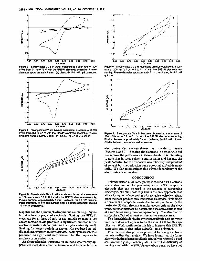
11. Voltammetric Characteristics. In polar solvents like water or nonpolar solvents like hexane the SPE/Pt electrode worked well. (For the reasons mentioned above, exposure to water was kept under 30 min.) Figure 3 is a cyclic voltam- mogram (CV) of hydroquinone in water without supporting electrolyte. This CV was virtually identical to CV's of hy- droquinone in 1 M sulfuric acid at an epoxy-shrouded Pt-wire electrode (0.7 mm diameter, reference and counter electrodes in the solution, not in the barrel). Figure 4 is a CV of quinone in hexane. Note that the electron-transfer rate for the qui- none/hydroquinone couple in hexane, as evidenced by the decreased peak separation, is greater than in water. It is also interesting to note that the 175-mV peak separation observed with this electrode for quinone in hexane is considerably less than the 400-mV separation reported by Kaaret and Evans for their Ndion/Pt composite under similar conditions (Figure 4 in ref 1).
In solvents of intermediate polarity such as the alcohols, acetonitrile, and ethyl acetate, there was very little if any
2382 ANALYTICAL CHEMISTRY, VOL. 83, NO. 20, OCTOBER 15, 1991
2-
1.5-
1 -
6 0.5-
a a
c 2 0-
-0.5-
-1 - -1.5-
-2-1
s. t -5 O S
b
a
VOLTAGE Flguro 3. Steady-state CV’s in water obtained at a scan rate of 100 mV/s from 0.1 to 0.75 V wlth the SPE/Pt electrode assembly, Pt-wire diameter approximately 7 mm: (a) blank, (b) 5.0 mM hydroquinone.
%O Oh0 0:70 OkO 0:50 0:40 0:30 0.’20 0:lO 200 VOLTAGE
Flguro 4. Steady-state CV’s in hexane obtained at a scan rate of 200 mV/s from 0.8 to 0.1 V wlth the SPE/Pt electrode assembly, Pt-wire diameter approximately 7 mm: (a) blank, (b) 2.1 mM quinone.
- 6
4
2
c o
-2
-4
-6
-8
3 z w
3
w -‘d90 O h 0:70 OkO 0:SO 0:40 0:30 0:20 0:lO O!W
VOLTAGE
Flguo 1. Steady state CV’s In ethyl acetate obtained at a scan rate of 100 mVls from 0.8 to 0.1 V with the SPElPt electrode assembly, Pt-We diameter approxknatdy 5 mm: (a) blank, (b) 5.0 mM quinone freah ekctrode, (c) 5.0 mM quinone aftw electrode assembly soaked 10 mln In acetonitrile.
response for the quinone/hydroquinone couple (e.g., Figure 5b) at a freshly prepared electrode. Soaking the SPE/Pt electrode for at least 10 min in acetonitrile to remove the excess formaldehyde produced a significant increase in the electron-transfer rate for quinone in ethyl acetate (Figure 5). Soaking for longer periods in acetonitrile produced no ad- ditional improvement in ethyl acetate. Soaking in acetonitrile produced no significant improvement for the response in alcohols or in acetonitrile.
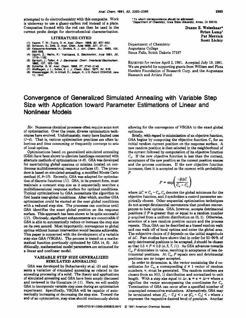
An electrochemical response for quinone was readily ap- parent in methylene chloride, benzene, and toluene, but the
00
Figwe 6. Steady-state CV’s in methylene chloride obtained at a scan rate of 200 mV/s from 0.8 to 0.1 V with the SPElPt electrode as- sembly, Pt-wire diameter approximately 3 mm: (a) blank, (b) 5.0 mM quinone.
-$!XI 0.’80 0:70 Oh0 0:50 0:40 0:30 0:20 0:lO O!OO VOLTAGE
Flguro 7. Steady-state CV’s in benzene obtained at a scan rate of 100 mV/s from 0.8 to 0.1 V with the SFWPt electrode assembly, Pt-wire diameter approximately 5 mm: (a) blank, (b) 5.0 mM quinone. Similar behavior was observed in toluene.
electron-transfer rate was slower than in water or hexane (Figures 6 and 7). Soaking the electrode in acetonitrile did not improve the performance in these solvents. It is interesting to note that in these solvents and in water and hexane, the peak potential for the oxidation was relatively independent of solvent but the reduction peak potential shifted dramat- ically. We plan to investigate this solvent dependency of the electron-transfer kinetics.
CONCLUSION Polymerization of an ionic polymer around a Pt electrode
is a viable method for producing an SPE/Pt composite electrode that can be used in the absence of supporting electrolyte. To our knowledge this is the only approach that allow formation of composites with a single electrode surface; other methods produce only microarray electrodes. This single surface in the composite is essential to our plan to verify the postulate (1) that electron transfer occurs only at the elec- trode/polymer interface by determining the active surface area at short times using chronoamperometry. We also plan to study the effect of solvent on the active surface area.
The formaldehyde/hydroxybenzenesulfonic acid polymer used here does not appear to be the ideal SPE for this ap- plication. Work continues in this lab to improve this SPE/Pt composite and to find other suitable ionic polymers.
This method also provides potential for using electrode materials other than metals. We have found that the form- aldehyde/ hydroxybenzenesulfonic acid polymer formed a good seal around a glassy-carbon plate. Due to the difficulty of making a cell with the SPE/glassy-carbon plate, we have not
Anal. Chem. 1001, 63, 2303-2306 2383
attempted to do electrochemistry with this composite. Work is underway to use a glassy-carbon rod instead of a plate. Composites formed with the rod can then be used in the current probe design for electrochemical characterization.
LITERATURE CITED (1) Kaaret, T. W.; Evans, D. H. Anal. Chem. 1988, 60, 657-662.
(3) Katayama-Aramata, A.; Ohnkhl, R. J . Am. Chem. Soc. 1983. 105,
(4) Ogumi. 2.; Nlshb, K.; Yoshlzawa, S. €lecP~&lm. Acta 1081, 26,
(5) Sanazin, J.; T a l k , A. J . Eleciroenel. W”. I n t w f a d e l E ~ .
(7) Wdmagen, J. L.; Soltes, E. J. J . Chem. Educ. 1977. 54, 619. (8) Wassemggw, H.: In Anhalt, D.: Jaeger, K. US. Patent 2204538, June
(2) SChiaVOn, G.; ZOtti, G. AMI. chlin. AClo 1989, 211, 27-41.
658-859.
1779-1782.
1982, 137, 183-188. (6) SchleffW. G. W. AMI . Chem. 1985. 57, 2745-2748.
11. 1940.
To whom correspondence should be addressed. ’Department of Chemistry, Iowa State Universlty, Ames, IA 50010.
Duane E. Weieshaar* Brian Lamp1 Pat Merrick Scott Lichty
Department of Chemistry Augustana College Sioux Falls, South Dakota 57197
RECEIVED for review April 2, 1991. Accepted July 19, 1991. We are grateful for supporting granta from William and Flora Hewlett Foundation of Research Corp. and the Augustana Research and Artists Fund.
Convergence of Generalized Simulated Annealing with Variable Step Size with Application toward Parameter Estimations of Linear and Nonlinear Models
Sic Numerous chemical processes often require some sort of optimization. Over the years, diverse optimization tech- niques have evolved. Unfortunately, many have limited uses (1-4). That is, various optimization practices are often la- borious and time consuming or frequently converge to sets of local optima.
Optimizations based on generalized simulated annealing (GSA) have been shown to alleviate handicaps concerned with alternate methods of optimizations (4-8). GSA was developed for ascertaining global maxima or minima located on con- tinuous multidimensional response surfaces (5). The proce- dure is b e d on simulated annealing, a modified Monte Carlo method (6,8-10). Recently, GSA was adapted for optimiza- tion of discrete functions (11). GSA, in its present form, must maintain a constant step size as it sequentially searches a multidimensional response surface for optimal conditions. Typical optimizations by GSA necessitate the algorithm to first locate near-global conditions. After which, another GSA optimization could be started at the near global conditions with a reduced step size. The processes can continue until GSA identifies the exact global position on the response surface. This approach has been shown to be quite successful (11). Obviously, significant enhancements are conceivable if GSA is able to automatically reduce or increase the step size on its own accord. Most importantly, convergence to global optima without human intervention would become achievable. This paper is concerned with the development of a variable step size GSA (VSGSA). The process is tested on a mathe- matical function previously optimized by GSA (4 , 5). Ad- ditionally, mathematical model parameters are estimated for a linear and nonlinear model.
VARIABLE STEP SIZE GENERALIZED SIMULATED ANNEALING
GSA was developed by Bohachevsky et al. (5) and repre- sents a variation of simulated annealing as related to the annealing processing of a solid. The theory and applications of simulated annealing and GSA have been amply discussed and reviewed in the literature (4-11). Here, we will modify GSA to incorporate variable step sizes during an optimization experiment. Specifically, VSGSA will be capable of auto- matically increasing or decreasing the step size. Toward the end of an optimization, step sizes should continuously shrink
allowing for the convergence of VSGSA to the exact global optimum. I
Briefly, with regard to “ h a t i o n of an objective function, GSA begins by computing the objective function C, for an initial random current position on the response surface. A new random position is then selected in the neighborhood of the current followed by computation of its objective function C,. If the new objective function is less than the current, acceptance of the new position as the current position ensues and the process continues. If the new objective function increases, then it is accepted as the current with probability P
P = exp( -) -PAC cc - c,
where AC = C, - C,, C, denotes the global minimum for the objective function, and j3 symbolizes a control parameter em- pirically chosen. Other sequential optimization techniques do not accept detrimental movements that produce conver- gences to local optima. GSA, however, accepts detrimental positions if P is greater than or equal to a random number p acquired from a uniform distribution on (0,l). Otherwise, selection of a new random position occurs and the process repeata. Thus, GSA can be described as a b d random walk and can walk off of local optima and enter the global area. The subjective choice of j3 depends on the initial magnitude of AC. Past studies have shown that in order for 5040% of early detrimental positions to be accepted, j3 should be chosen so that 0.5 P < 0.9 (4 ,5 , 7,11). As GSA advances towards C,, P diminishes in value, resulting in acceptance of less de- trimental positions. At C,, P equals zero and detrimental positions are no longer accepted.
In order to determine, n, the vector containing the d co- ordinates for C,, a corresponding d X 1 vector of random numbers, v, must be generated. The random numbers are chosen from an N(0, l ) distribution and normalized to unit length. With a step size equal to Ar, n = c + Arsv where c signifies the vector encompassing the coordinates for C,. Termination of GSA can occur after a specified number of unaccepted consecutive evaluations. Alternatively, GSA may be terminated when IC, - C,l < c or IC, - C,l < c where c expresses the respective desired level of precision. Another
0003-2700/9 1 /0363-2383$02.50/0 Q 199 1 American Chemical Soclety