fabrication of microcontroller based dip-casting for thin...
TRANSCRIPT
American Journal of Science and Technology
2015; 2(3): 111-115
Published online April 30, 2015 (http://www.aascit.org/journal/ajst)
ISSN: 2375-3846
Keywords Dip Casting,
Pic-Microcontroller,
Stepper Motor,
Alumina,
Poly-Ethylene Glycol,
Optical Characterization,
Proteus 7.6 Professional,
Olympus Optical Microscope
Received: March 25, 2015
Revised: April 16, 2015
Accepted: April 17, 2015
Fabrication of Microcontroller Based Dip-Casting for Thin Films Depositions
Srinivasan E.1, Vanchinathan T.
2, Siva Kumar G.
3
1Department of Electronics and Communication Engineering, Panimalar Engineering College,
Chennai, India 2Centre of Nanotechnology and Research, VIT University Vellore, India 3Department of Chemistry, Panimalar Engineering College, Chennai, India
Email address [email protected] (Srinivasan E.), [email protected] (Vanchinathan T.),
[email protected] (Siva K. G.)
Citation Srinivasan E., Vanchinathan T., Siva Kumar G.. Fabrication of Microcontroller Based Dip-Casting
for Thin Films Depositions. American Journal of Science and Technology.
Vol. 2, No. 3, 2015, pp. 111-115.
Abstract An automated dip coater capable of coating thin films of less or greater than one micron
from nano suspensions has been designed and fabricated using microcontroller
controlled stepper motor. Various off-the-shelf components have been integrated to build
a cost effective, customizable, versatile kit. The setup is used to coat thin films of
photoresist material such as alumina, and poly-ethylene glycol composite on substrates
to achieve uniform thickness. The automated system outperforms manual systems by
allowing constant dipping speeds in the range of 10 to 100mm per second. The
repeatability, reproducibility of the fabricated dip coater is excellent and the ease of use
is comparable to that of commercial kits. The design considerations and selection criteria
for the components are discussed in this paper. Finally, a thin film of alumina based
ceramic and alumina-polymer composite thin film was made and characterized using
optimal microscopy to view particles sizeses and behaviours.
1. Introduction
Dip coating is a simple, industrially popular method for forming thin films. The
function of the dip coater is to hold, dip and raise the substrate into and out of a
suspension photoresist liquid at controlled speed so that thin films can be formed based
on the viscous drag of the liquid against gravitational force. In some cases, it is
advantageous to dry the samples soon after they are removed from the liquid [1]. Dip
coating process can be employed in fabrication of photovoltaic solar cells,
semiconductor industry and fuel cell electrolyte layers [2].
The dip coater machine consists of stepper motor, stepper motor driver circuitry and
controller unit mounted on a stand. The stepper motor moves the sample from a start
point to the bowl (bowl point) containing coater solution in vertical direction [3]. After
dipping the sample in the coater solution, it takes the sample to the drier point which is
located at a height of approximately 30 cm above the bowl point for drying the sample in
the drier unit. The drier here is activated by a relay circuitry. Now the sample is again
taken to the start point, where we load and unload the sample. The whole process
mentioned above is fed to the controller unit PIC-Microcontroller 16F877A [4].
The sample is loaded to the dip coater with the help of sample holder which is
suspended through a string. The controller unit and the stepper motor is fixed in a metal

112 Srinivasan E. et al.: Fabrication of Microcontroller Based Dip-Casting for Thin Films Depositions
stand which is made strong enough to withstand the vibration
of the steppermotor and remain stable. Switches are given to
select the mode of operation. Changes can be made in the
program and burned into the IC, in order to obtain required
resolution of the dip coater. For large area deposition as size
poses a major limitations a dip casting is instigated and indeep
surprising to observe, thinfilms as prepared in this study
irrespective of the dip coating methodologies outperform their
amorphous or polymer analogues owing their superior
chemical and physical properties [5]. In order to obtain a micro
structured thin film with desired structural and morphological
properties under dip-coating process [6, 7].
Polyethylene glycol (PEG) mostly used for thin film
depositions; PEG is a oligomer or polymer compound with
many applications from industrial manufacturing to medicine.
PEG is a less molecular mass about 20,000g/mol, having low
melting solid [8]. PEG is suitable for fabrication of thin films
due to its good adhesion properties, also having high
depositing quality along with uniformity with precise thick
and thin film. PEG films are used in pharmaceutics [14],
cosmetics, and textile and leather industry for paper, plastics,
rubber and printing purposes [9, 10]. PEG’s chemistry,
biological amenability and excellent solubility, widely
accepted the properties of PEG conjugates resides from the
unique combination of physicochemical and biological
properties of polymer [11, 12]. Effectively in thin film
making, drug delivery and diagnosing, where it functions as a
membrane through which drug is slowly released [13].
Polyethylene glycol is highly hydrophilic, its response to
water vapor and its thickness can be controlled by changing
the relative humidity [15,16]. Permeation properties of PEG
are depends on the chemical microstructure, crystallinity, and
morphology of monomer, permeant properties like, size and
shape determine transport properties. The permeability
depends on the solubility of polyethylene glycol, simply
polymer [17].
2. Design Parameters and Tools
2.1. Mechanical Design
It consists of a metal stand to hold the stepper motor. The
substrate suspended using nylon string is moved
verticallyfrom sample loading point to bowl point and in
reverse.i.e. from bowl point to loading point by geared
spindle arrangement which is coupled with stepper motor
through a shaft. The operating height is 60cm; the drier is
placed in between at a height of 30 cm. The drier may be
heating filament or halogen-lamp which produces heat for
drying the sample and the width of the equipment is 45cm.
The sample is held near the drier point for drying which is
defined in the program sequence.
2.2. Electronic Design
It is used to give the required pulse to the driver unit to
operate the stepper motor as defined in the program coding.
Stepper motors provide a means for a precise positioning and
speed control without the use of sensors. Other than the
normal Microcontrollers PIC Family, the 16F877A PIC
controller supports more features (discussed below), so we
have chosen this PIC-controller as the main controller. The
most commonly used Character based LCDs are based on
Hitachi's HD44780 controller were used for our display unit.
They can be interfacing with various microcontrollers.
Various interfaces (8-bit/4-bit), programming, special stuff
can be done with this LCD displays [18].
2.3. Supply Section
Fig 1. Power supply unit [4].
AC is applied to the primary winding of the power
transformer it can either be stepped down or up depending on
the value of DC needed. In our circuit the transformer of
230v/15-0-15v is used to perform the step down operation
where a 230V AC appears as 15V AC across the secondary
winding A bridge rectifier of four diodes (4*IN4007) are
used to achieve full wave rectification and to achieve a AC to
DC Conversion
2.4. Opto-Coupler and Amplifier Section
Fig 2. Optocoupler and amplifier section.
In Fig 2 we have used CNY 17-2 opto-coupler, It consists
of Gallium Arsenide IR emitting diode optically coupled to a
monolithic silicon photo transistor detector. A reverse biased
diode is connected in parallel with the coil of the stepper
motor. When the coil is demagnetizing it produce high back
emf which destroys TIP122 which is in the cut off state. This
can be avoided by this diode. The power transistor is used to
amplify the current from milli amps to few amps (.i.e. from
50mA to 2mA.)

American Journal of Science and Technology 2015; 2(3): 111-115 113
2.5. Coding Language and Software
In this project Embedded C is used for programming the
PIC (16F877A). The program consist of main program for
forward and reverse movement. The sub programs which
consist of delays while performing the operation. There are
five sub programs delay at start point, delay at bowl point,
and the delay at drier point. Display interface and relay
operation at drier are called while performing the dip coating
operation. Proteus version 7.6Professional simulation
software was used to simulate the operation of the dip coater
is showed below fig 3.
Fig 3. Simulation part using Proteus s/w
In this simulation software we can check actual working of
the controller and the driver circuit by giving inputs to the
simulation software. It is an easy way to test the performance
of the coating technique and change the coding as we
required in the simulation for future change of work. The
results of the simulations help to fabricate the dip-coater
which launch in way of hardware implementations.
3. Experimental Setup
Fig 4. Dipcasting setup
The Fig 4 shows the single vessel dip coater. The dip
coater range is divided in two types, either single or multiple
vessel systems. The single vessel dip coater is used to deposit
from one solution while the multiple vessel system allows
many solutions which can include cleaning or rinsing. The
“single vessel” and “multi-vessel” categories both offer
Small, Medium and Large systems to cater for a large range
of sample sizes. You can choose from sample weight, sample
size, number of samples, dipper movements and number of
vessels required by changing the program
3.1. Setup Implementation Parameters
Table Setup implementation parameters
Sno Parameters Dimensions
1 Weight of the mechanical design 12.7Kg
2 Height of the system 75cm
3 Width 45cm
4 No of samples used 6 Glass Slides
5 Coated samples Alumina-PEG
3.2. Glass Cleaning Procedures
Initially a glass slide (75mm long x 25mm wide), which
was cleaned by using various chemicals and acids. Glass
slide is rinsed in soapy water for 2 hours after again soak in
concentrated hydrochloric acid (HCL), Nitric acid (HNO3)
finally acetone bath for removing the oil residues and other
contaminated particles on the surface of the glass slide.
114 Srinivasan E. et al.: Fabrication of Microcontroller Based Dip-Casting for Thin Films Depositions
3.3. Fabrication and Characterization of Thin
Films
To prepare thin films by dip coating, substrate were
deposit on glass slide, Slurry was prepared by dispersing
Alumina in water. Alumina (activated, neutral) was procured
from Aldrich,India was a micron sized particle having wide
particle size distribution. 1gm of alumina was stirred with 30
ml of water in a magnetic stirrer for 5 minutes to prepare the
slurry. The slurry used for dip coating alumina- polyethylene
glycol composite was made by adding 200 mg of
polyethylene glycol (PEG), molecular weight ~4000 obtained
from Aldrich, India. This was also stirred in a magnetic
stirrer for 5 minutes and PEG being a water soluble polymer
dissolved completely. This altered the viscosity of the
solution and this was also used for dip coating. Dip coating
was done at 30 mm/sec rate and dwell time was 5 seconds.
An optical microscope, Olympus coupled with analysis
software for image acquisition and analysis was used for
obtaining the images.
4. Results and Discussions
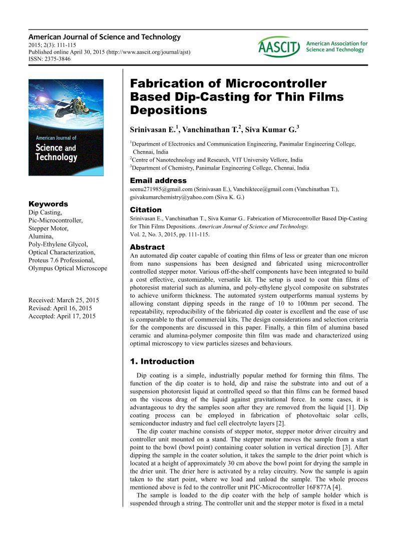
Fig5.Shows the photocopy dip coater equipment designed
by us. Using the dip coater we can coat thin film of
thecoatersolution(egpolymer based poly ethylene
glycol)onaglassslideofseveralmicrons(range<1microntofew
microns). The dip coater can be used to coat thin or thick film
on the glass slide according to the delays defined by the user
at start point, bowl point, and drier point. The thin film
coated will be in the range of several microns. The resolution
obtained .i.e. the dipping speed in the range of approximately
(30-200) mm/sec. After the deposition of chemical
compositions such as alumina and poly-ethylene glycolkept
for the drying process done by 500W halogen lamp for 10
seconds to bring film in good stability and less gluing
property. The stepper motor was under ideal state for 5 to 20
seconds, which is effectively created by the delay unit.
Fig 5. Photocopy of Dip-coater
Theresolutioncanbechangedbydoingsomechanges such as
incrementing duration forsubstrate bath (dipping in bowl),
increasing time for drying and so on inthedesignofthe
equipment. We are using string to suspend the glass slide in
the solution which will provide low resolution due to
vibration of the stepper during operation using this dip coater
we can obtain thin films suspensionphotoresist on the glass
slide in the range of less than 1 micron to few microns.
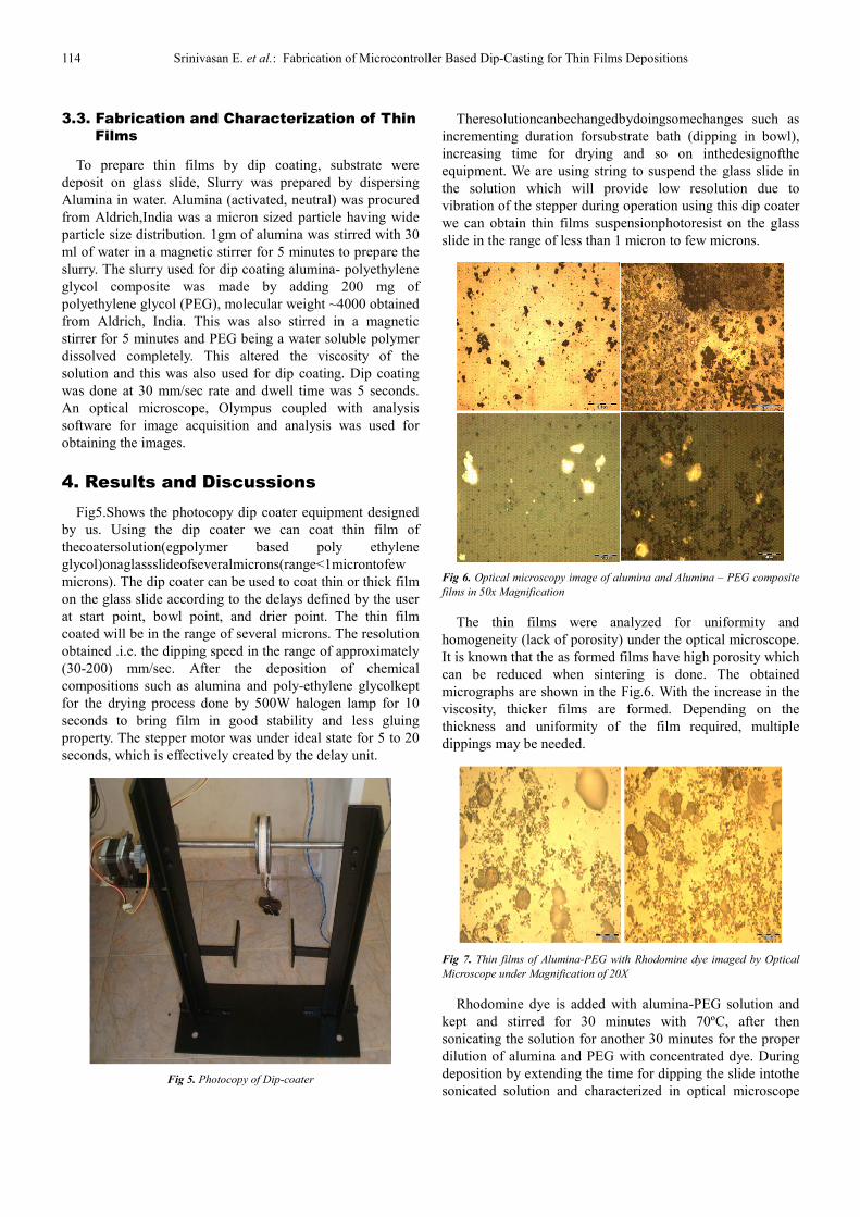
Fig 6. Optical microscopy image of alumina and Alumina – PEG composite
films in 50x Magnification
The thin films were analyzed for uniformity and
homogeneity (lack of porosity) under the optical microscope.
It is known that the as formed films have high porosity which
can be reduced when sintering is done. The obtained
micrographs are shown in the Fig.6. With the increase in the
viscosity, thicker films are formed. Depending on the
thickness and uniformity of the film required, multiple
dippings may be needed.
Fig 7. Thin films of Alumina-PEG with Rhodomine dye imaged by Optical
Microscope under Magnification of 20X
Rhodomine dye is added with alumina-PEG solution and
kept and stirred for 30 minutes with 70ºC, after then
sonicating the solution for another 30 minutes for the proper
dilution of alumina and PEG with concentrated dye. During
deposition by extending the time for dipping the slide intothe
sonicated solution and characterized in optical microscope

American Journal of Science and Technology 2015; 2(3): 111-115 115
through objective lens (10/0.25NA) 20x magnification, in
that films contains particles are get agglomerated and created
a bumps size of ~20microns in range, and some of the
particles are formed the grains in size of approximately
985nm and 991nm which are showed in the Fig.7. Further
work is required to characterize these films in to various
techniques. An automated dip coating unit with controlled
dipping speed and dwell time in solution and heater zone has
been fabricated along with hardware implementation.
5. Conclusion
Thin film deposition are achieved bydipping processie
glass slide was simply be inserted and removed from the
slurry, with help of stepper motor which was effectively
controlled by Pic-microcontroller, Alumina-PEGfilm
substrate get uniform deposition, with rough surface due to
vibration of stepper motor, film was characterized by optical
microscope with various magnification objective lenses, in
that particles are forms as uncircled bubbles, some group of
particles are agglomerated with the size of several microns,
well diluted particles are in form of grains with various
nanometered in sized, Further studies in making thin films of
photoresist and other materials are being carried out with
various dilution methods by increasing stirring timings for
well dilution of solvents for reducing the surface roughness,
using various curing process for drying to remove the
furthergluing property of the film, by varying the angle of
rotation of the stepper motor possible to avoid more vibration,
and characterized those samples in Near-field Scanning
Optical Microscope (NSOM) and Nano Scratch Tester (NST)
to get a high resolution and better accuracy compare to the
present.
References
[1] HenningLuebbe, Jan Van herle, HeinrichHofmann,Paul Bowen, Ulrich Aschaue, Andreas Schuler, Frans Snijkers, Hans-Juergen Schindler, Ulrich Vogt, Cécile Lalanne, “Cathode- supported micro-tubular SOFCs basedonfabrication and characterization of dip-coat edelectrolyte layers”, Solid State Ionics, Vol180, (2009) 805–811.
[2] Geffcken W. And Berger E., Deutsches Reichspatent,”Optics of Thin Films”, Vol736411, May 6,(1989) Page 455-465.
[3] Brinker C. J, and Alan J. Hurd, ‘Journal dephysique Archives’,
“Fundamentals of Sol-GelDip-Coating”, Vol 4, 1994, Page 1231-1242.
[4] Data Sheet of stepper motor and PIC16F87XAMicrocontroller (2003 Microchip TechnologyInc)
[5] M. Deepa, T.K. Saxena, D.P. Singh, K.N. Sord,S.A. Agnihotry, ”Electrochimica Acta”, Vol 51,(2006), Page:1974-1989.
[6] R.Ashiri, A.Nemati, M.Sasani Ghamsari,“Ceramics International”, Science direct, Vol40,(2014), Page: 8613-8619.
[7] Rocio Bayon, Gema San Vicente, Angel Morales,“Solar Energy Materials & Solar Cells”, Vol94,(2010), Page: 998-1004.
[8] Ji Chen, Scott K.Spear, Jonathan. G, Huddlestonand Robin D. Rogers, “Green Chemistry Organisation”, Vol 7, (2005), Page: 64-82.
[9] George W. Greene, Lisandra L. Martin, Rico F.Tabor, Agnes Michalczyk, “Biomaterials”,Science direct, Vol 53, (2015), Page 127-136.
[10] A.Purice, J. Schou, P.Kingshott, N.Pryds,M.Dinescu, “Applied Surface Science”, Sciencedirect, Vol 253, (2007), Page: 7952-7956.
[11] R. Cristescu, C. Popescu, A. C. Popescu, S. Grigorescu, L. Duta, I. N. Mihailescu, ”Applied Surface Science”, Science direct, Vol 255(2009), Page 5605-5610.
[12] R. Cristescu, C. Popescu, A. Popescu, S. Grigorescu, I.N. Mihailescu, ”Applied Surface Science”, Science direct, Vol 255, (2009), Page:9873-9876.
[13] Weixin Huang, Ming Lei, HoungHaung, JunchiChen, Huanqin Chen, “Surface & CoatingTechnology”, Science Direct, Vol 255, (2010),Page: 3954-3961.
[14] Li-Li xu, Li-Li Shi, Qing-Ri Cao, Wei-Juan Xu,YueCaa, Jing-Hao Cui, “International Journal of Pharamaceutics”, Science Direct, Vol 473, (2014), Page 598-406.
[15] SabriyeAcikgoz, HasanYungevis, AmitarSanyal, M. NaciInci, “Sensor & Actuators”, Manuscript, (2015), Page 1-28.
[16] Junliu, Bin Ni, Liang Zhu, Jun Yang, XiaejianCao, Wei Zhou, “The Spine Journal”, BasicScience, Vol 10, (2010) Page: 441-447.
[17] Anja Car, ChrtomirStropink, WilfredoYave,Klaus-Viktor Peinemann, “SeparationPurification Technology”, Science Direct, Vol62, (2008), Page: 110-117.
[18] www.labcenter.com