fabrication of directly designed gears with symmetric and ... of directly... · table 1 main...
TRANSCRIPT

Fabrication of Directly Designed Gears with Symmetric and Asymmetric TeethAlexander L. Kapelevich and Yuriy V. Shekhtman
IntroductionWhen compared with the tradit ional gear design approach — based on pre-selected, typically standard generating rack parameters — the alternative Direct Gear Design (Ref.1) method provides certain advantages for custom, high-perfor-mance gear drives. Among them are increased load capacity; efficiency; length-of-service; reduced size and weight; noise/vibrations; and cost. However, the manufacture of such non-standard gears requires custom tooling and certain alterations of known gear fabrication processes.
This paper presents specifics of application main methods of gear fabrication, i.e. — form and generating machining (cutting and grinding); gear forming injection molding technology; net forging; powder metal (PM) processing; die casting; and wire EDM gear prototyping. It also describes tooling profile defini-tion, dependent upon the selected gear fabrication method. It presents the Genetic Molding Solution technique for compensa-tion of differential warpage and shrinkage for plastic injection molding tooling — that enables enhancement of gear accuracy and shortens the process development cycle.
Table 1 Main machining processes used for spur and helical gearsType of process Type of tooling
Form Machining
Cutting Form disk or end mill cutter, broach, etc.Grinding Grinding wheel
Generating Machining
Cutting Hob, shaper cutter, rack cutter, shaver cutter
Grinding Grinding wheel
Contour Machining
CNC milling Cylinder or ball mill cutterWire-cut EDM WireLaser cutting Laser beam
Water Jet cutting Water or water and abrasive media mixture stream
Figure 1 Gear form machining: 1) gear profile; 2) tool profile.Figure 2 Gear fly cutting schematics: a) top view; b) right view; c)
isometric view.
a
b
c
asymmetric
For Related Articles Search
at www.geartechnology.com
86 GEAR TECHNOLOGY | November/December 2014[www.geartechnology.com]
technical

Gear MachiningForm machining. In the form gear cutting or grinding process (Fig. 1), a tool profile is the same as a space profile between gear teeth; this process is applicable for spur and helical gears. A form machining tool is unique for every gear tooth profile and its cost is practically the same for standard or custom-directly designed gears. Note: accuracy of form-cutting-tool-positioning relative to the gear blank is critically important.
In gear form machining, usually one tooth is machined after another. When machining of one tooth is completed, the index-ing device (rotary table) positions a gear blank for the next tooth cutting. But there is one type of form machining process, i.e. — gear fly cutting (Ref. 2) — that has a tool (fly cutter) in mesh with the gear blank (Figs. 2–3). It uses conventional gear hobbing machines that have a cutter and gear blank in constant synchro-nized rotation. However, unlike the gear rack generating process, the space between teeth is shaped by a whole cutter tooth pro-file — exactly as in conventional form machining with the disk cutter (Fig. 1).
The gear fly cutter also looks similar to the conventional gear disk cutter, but all cutter edges are turned at the start angle ϕ that is defined as:
(1)
ϕ = arcsin mn ntdt
where: mn is the normal module of the gear nt is the number of the fly cutter teeth dt is the fly cutter pitch diameter
A gear fly cutter also can be considered as the multi start gear hob that has just one tooth in each start. The cutter set up angle ϕ relative to the gear plane is defined the same way as for gear hobbing:
(2)φ = β ± ϕ
where: β gear helix angle, sign “+” if the gear helix and cutter start
angle have similar directions (right or left); and sign “–” if the gear helix and cutter start angle have opposite directions.
The adjustable gear fly cutter is shown in Figure 3b; it makes possible the machining of gears with different numbers of teeth and modules by using replaceable cutting and angle inserts.
Generating machining. Schematics of the rack generating gear cutting or grinding process are shown in Figure 4. In this process a gear blank and tool are engaged in a mesh, and all gear teeth are machined practically simultaneously. In traditional gear design the tooling (a hob or rack cutter) profile is deter-mined early on in the gear design procedure. In combination with its position relative to the gear center (addendum modifi-cation or X-shift), the tooling rack profile defines the gear tooth and whole gear profiles.
Direct Gear Design applies a different approach. The opti-mized gear tooth and whole gear profiles are described without
Figure 3 Gear fly cutting: a) hobbing machine set-up; b) adjustable fly cutter with inserts.
Figure 4 a. rack generating: 1) gear profile; 2) hob or rack cutter profile; b. asymmetric gear hob cutter.
87November/December 2014 | GEAR TECHNOLOGY
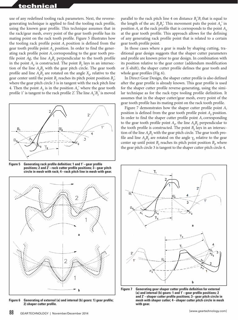
use of any redefined tooling rack parameters. Next, the reverse-generating technique is applied to find the tooling rack profile, using the known gear profile. This technique assumes that in the rack/gear mesh, every point of the gear tooth profile has its mating point on the rack tooth profile. Figure 5 illustrates how the tooling rack profile point At position is defined from the gear tooth profile point Ag position. In order to find the gener-ating rack profile point At corresponding to the gear tooth pro-file point Ag, the line AgBg perpendicular to the tooth profile in the point Ag is constructed. The point Bg lays in an intersec-tion of the line AgBg with the gear pitch circle. The gear tooth profile and line AgBg are rotated on the angle Xg, relative to the gear center until the point Bg reaches its pitch point position Bg’, where the gear pitch circle 3 is in tangent with the rack pitch line 4. Then the point Ag is in the position Ag’ where the gear tooth profile 1’ is tangent to the rack profile 2’. The line Ag’Bg’ is moved
parallel to the rack pitch line 4 on distance Bg’Bt that is equal to the length of the arc BgBg’. This movement puts the point Ag’ in position At at the rack profile that is corresponds to the point Ag at the gear tooth profile. This approach allows for the defining of any generating rack profile point that is related to a certain gear tooth profile point.
In those cases where a gear is made by shaping cutting, tra-ditional gear design suggests that the shaper cutter parameters and profile are known prior to gear design. In combination with its position relative to the gear center (addendum modification or X-shift), the shaper cutter profile defines the gear tooth and whole gear profiles (Fig. 6).
In Direct Gear Design, the shaper cutter profile is also defined after the gear profile is already known. This gear profile is used for the shaper cutter profile reverse-generating, using the simi-lar technique as for the rack-type tooling profile definition. It assumes that in the shaper cutter/gear mesh, every point of the gear tooth profile has its mating point on the rack tooth profile.
Figure 7 demonstrates how the shaper cutter profile point At
position is defined from the gear tooth profile point Ag position. In order to find the shaper cutter profile point At corresponding to the gear tooth profile point Ag, the line AgBg perpendicular to the tooth profile is constructed. The point Bg lays in an intersec-tion of the line AgBg with the gear pitch circle. The gear tooth pro-file and line AgBg are rotated on the angle γg relative to the gear center up until point Bg reaches its pitch point position Bg, where the gear pitch circle 3 is tangent to the shaper cutter pitch circle 4.
Figure 5 Generating rack profile definition: 1 and 1’ – gear profile positions; 2 and 2’ – rack cutter profile positions; 3 – gear pitch circle in mesh with rack; 4 – rack pitch line in mesh with gear.
Figure 6 Generating of external (a) and internal (b) gears: 1) gear profile; 2) shaper cutter profile.
a
b Figure 7 Generating gear shaper cutter profile definition for external (a) and internal (b) gears: 1 and 1’ – gear profile positions; 2 and 2’ – shaper cutter profile positions; 3 – gear pitch circle in mesh with shaper cutter; 4 – shaper cutter pitch circle in mesh with gear.
a
b
88 GEAR TECHNOLOGY | November/December 2014[www.geartechnology.com]
technical
The angle γg is:(3)
γg =BgBg’dpt
where: BgBg’ is the length of arc BgBg’ dpg is the gear pitch diameter in the mesh with the shaper
cutter
Then the point Ag is in the position Ag’ where the gear tooth profile 1’ is tangent to the shaper cutter profile 2’. The line Ag’Bg’ is rotated back relative to the shaper cutter center on angle γt
that is:(4)
γt = γgdpg
dpt
where: dpg is the gear pitch diameter in the mesh with the shaper
cutter.
This movement puts the point Ag’ in position At at the shaper cutter profile that corresponds to point Ag at the gear tooth pro-file. This approach allows definition of any shaper cutter profile point corresponding to a certain gear tooth profile point.
The gear pitch diameter in mesh with generating tooling (hob, rack or shaper cutters) is not necessarily equal to the operat-ing pitch diameter with the mating gear. Accordingly, the pres-sure angle in mesh with the generating tooling can differ from the operating pressure angle. The pressure angle in mesh with the generating tooling selection is important. An extreme pres-sure angle (close to zero) results in a tooling profile that cannot sustain the required gear profile, due, for example, to the point-ed tooling tooth tip or its overly small radius. It also adversely affects cutting condition, gear tooth profile surface finish, and tooling life.
One of the benefits of the generating gear process is the abil-ity of using one tool (hob, rack or shaper cutter) for machining gears with different numbers of teeth. This allows reduction of tooling inventory and cost of low- and medium-volume gear production where tooling-share-per-one-gear is relatively high. In general, traditionally designed mating gears are machined with the same generating gear cutter; however, in mass gear production, gear cutting (or grinding) machines are typical-ly set up to machine one gear and they use a dedicated set of tools — including the gear cutters.
Directly designed gears require a custom-dedicated generat-ing tool for every gear with a different number of teeth. This increases tooling inventory and gear cost when production vol-ume is low. Although, even in this case, application of directly designed gears can be beneficial if their improved performance justifies a production cost increase — like, for example, in aero-space and racing transmissions. In mass gear production, a share of custom-dedicated-machining-tool-per-gear is low and, as a result, the cost of directly designed gears becomes practi-cally equal to traditional gears. This makes them applicable and sensible for automotive, agriculture, and other industries. Reverse-generating of the tooling profile from the gear profile is applicable for involute as well as for non-involute gears.
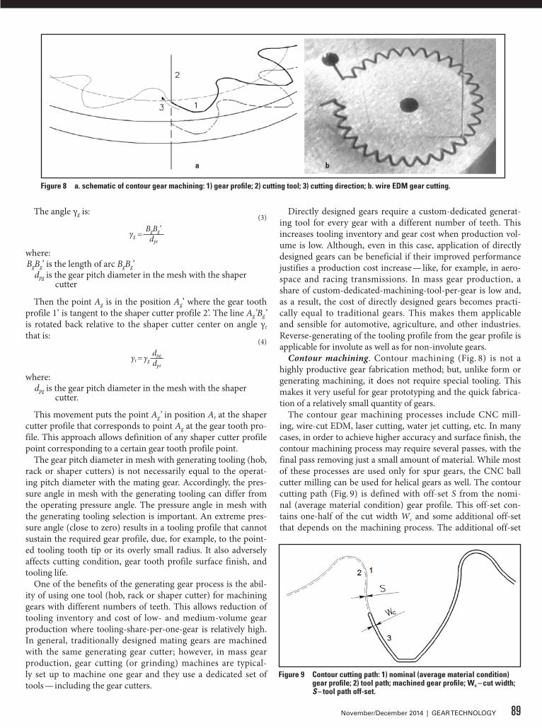
Contour machining. Contour machining (Fig. 8) is not a highly productive gear fabrication method; but, unlike form or generating machining, it does not require special tooling. This makes it very useful for gear prototyping and the quick fabrica-tion of a relatively small quantity of gears.
The contour gear machining processes include CNC mill-ing, wire-cut EDM, laser cutting, water jet cutting, etc. In many cases, in order to achieve higher accuracy and surface finish, the contour machining process may require several passes, with the final pass removing just a small amount of material. While most of these processes are used only for spur gears, the CNC ball cutter milling can be used for helical gears as well. The contour cutting path (Fig. 9) is defined with off-set S from the nomi-nal (average material condition) gear profile. This off-set con-tains one-half of the cut width Wc and some additional off-set that depends on the machining process. The additional off-set
Figure 9 Contour cutting path: 1) nominal (average material condition) gear profile; 2) tool path; machined gear profile; Wc – cut width; S – tool path off-set.
Figure 8 a. schematic of contour gear machining: 1) gear profile; 2) cutting tool; 3) cutting direction; b. wire EDM gear cutting.
a b
89November/December 2014 | GEAR TECHNOLOGY

may include a stock for final machining, over-cut or over-burn (for wire EDM and laser machining), and/or a defective layer that should be removed by a tooth surface treatment operation; e.g. — polishing.
Gear FormingForming gear fabrication processes. Plastic and metal injec-tion molding; powder metal processing; net forging; stamping; die casting; extrusion; gear and worm rolling; etc. are very cost-efficient for mass-produced gear drives. Most of these forming gear fabrication processes have a similar tooling component that actually defines a gear shape and its accuracy, i.e. — a tooling (mold or die) cavity. Any gear forming process cavity is dedicat-ed to a particular gear profile, which makes Direct Gear Design very acceptable for gear forming technology, as the production cost of the custom-optimized gears is practically the same as that of the similar-sized, standardized gears.
The cavity has a profile similar to the gear — but adjusted for shrinkage and warpage (Fig. 10) that greatly affects both gear size and shape accuracy. This makes the accurate prediction of shrinkage and warpage critical for all gear forming technolo-gies — but particularly for the plastic injection molding process. Plastic gears often have intricate body shape, including ribs or spokes to maintain limited, maximum material thickness to exclude voids, and/or for weight and cost reduction. They also are often incorporated as one piece with other mechanism com-ponents such as, for example, shafts, cams, etc. These design specifics, in combination with a huge variety of available gear polymers and enhancing additives (for increased strength, ther-mo resistance, lubricity, etc.) make prediction of gear shrink-age and warpage an extremely difficult process. In many cases, gear molders rely on a sometimes costly trial-and-error meth-od — with varying degree of success. Typically, this “educated guess” method works better for gears with relatively simple body shapes (like, for example, the flat uniform disks with small cen-tral holes) that are made out of generic unfilled polymers.
A totally different approach to molding distortion compen-sation is proposed in the literature (Ref. 3), referred to as the
Genetic Molding Solution. Similar to how DNA contains genetic information about the entire living organism, the shape of the molded part reflects the originally designed profile, polymer material properties, tooling design, and molding process param-eters. The Genetic Molding Solution method is based on math-ematical prediction that defines a transformational function describing relations between the initially molded sample gear profile and its actual, initial cavity profile. Once this function is defined, the target gear profile replaces the first molded sample profile as the transformational function variable to calculate the final cavity profile. The transformational function is based on a system of trigonometric and polynomial functions.
The initial cavity profile coordinates are:(5)
M1 = Ksh × Dwhere: D target gear profile data set, presented as X,Y coordinate
points of the 2D CAD model typically constructed for average material conditions
Ksh polymer linear mold shrinkage coefficient provided by the material supplier. These initial cavity profile coordinates M1 can be also presented as:
(6)M1 = f(P)
where: P initial sample gear profile data set, presented as X,Y
coordinate points provided by the CMM inspection of actual molded gear
f transformation function describing relations between the initial cavity and initial sample gear profiles
Then the final cavity profile coordinates are:(7)
M2 = f(D)
Unlike previously mentioned approaches, the Genetic Molding Solution method is based on the “black box” con-cept and uses only gear and cavity inspection results and math that define transformation function between them. It does not require knowledge of any specific data related to polymer mate-rial, tooling, and molding process parameters.
Practical application of this method entails eight steps:(1) Target gear profile definition (data file #1). The X,Y coor-
dinate points extracted from the gear CAD model present a desired nominal gear profile at average material condition. A number of these coordinate points are typically several-hun-dred-per-one-gear-tooth.
(2) Initial cavity profile definition. Initial cavity profile is the scaled up target gear CAD profile using the polymer linear mold shrinkage coefficient Ksh from its specification.
(3) Fabrication and inspection of initial mold cavity (data file #2). CMM inspection produces the X, Y coordinate points (several-hundred-per-one-tooth-space) accurately describing the initial cavity.
(4) Molding process optimization. Gears are molded using the initial cavity, without concern about the gear shape. A goal here is to achieve a stable and repeatable molding process with the part dimensional variation significantly lower than the required accuracy tolerances. Any material flaws — voids, for example — are unacceptable. Once this goal is reached, the molding process must be “locked in” and certified; no changes
Figure 10 Gear molding; 1) gear profile; 2) mold or die cavity profile.
90 GEAR TECHNOLOGY | November/December 2014[www.geartechnology.com]
technical
to the process are now allowed. Using the opti-mized process, several dozen gears are molded.
(5) Representative gear specimen selection. All molded gears are roll tested and inspection data is analyzed. The single-most representative pre-liminary gear specimen is selected. This specimen should have average statistical tooth-to-tooth and total composite errors (TTE and TCE).
(6) Gear specimen inspection (data file #3). CMM inspection produces the X, Y coordinate points (several-hundred-per-one-gear-tooth) accurately describing the initial cavity. Inspection data of the initial cavity and the gear specimen must have the same axes orientation to provide the each gear tooth and its cavity space accordance.
(7) Final cavity profile definition and fabrication. The Genetic Molding Solution software uses the gear specimen and initial cavity data (files #2 and #3) to generate a transformation function f. The target gear data (file #1) is then used as the vari-able of this transformation function to define the final cavity profile, or output data set. The same axes orientation of all three data file is absolutely critical. Any angular rotation or mirroring of the data points totally compromises the mold cavity adjustment results. The final cavity manufactured and then undergoes a CMM check-inspection.
(8) Final gear profile. And last, gears are molded using the final mold cavity. The CMM data of the molded gears should be identical to the specified gear profile, within the molding pro-cess accuracy variation.For successful application of the Genetic Molding Solution
method, the initial and final gear molding must be done with the same-batch polymer, on the same molding press, using the same tool. The current version of the software uses the 2D data sets and works well for spur plastic gears with relatively low face width. For helical and wide spur gears, this method should be used for several (typically 2 – 3) gear sections.
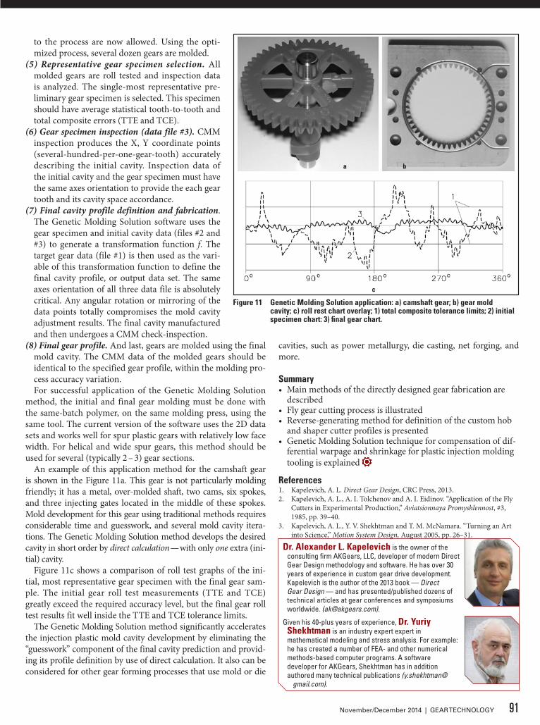
An example of this application method for the camshaft gear is shown in the Figure 11a. This gear is not particularly molding friendly; it has a metal, over-molded shaft, two cams, six spokes, and three injecting gates located in the middle of these spokes. Mold development for this gear using traditional methods requires considerable time and guesswork, and several mold cavity itera-tions. The Genetic Molding Solution method develops the desired cavity in short order by direct calculation — with only one extra (ini-tial) cavity.
Figure 11c shows a comparison of roll test graphs of the ini-tial, most representative gear specimen with the final gear sam-ple. The initial gear roll test measurements (TTE and TCE) greatly exceed the required accuracy level, but the final gear roll test results fit well inside the TTE and TCE tolerance limits.
The Genetic Molding Solution method significantly accelerates the injection plastic mold cavity development by eliminating the “guesswork” component of the final cavity prediction and provid-ing its profile definition by use of direct calculation. It also can be considered for other gear forming processes that use mold or die
cavities, such as power metallurgy, die casting, net forging, and more.
Summary• Main methods of the directly designed gear fabrication are
described• Fly gear cutting process is illustrated• Reverse-generating method for definition of the custom hob
and shaper cutter profiles is presented• Genetic Molding Solution technique for compensation of dif-
ferential warpage and shrinkage for plastic injection molding tooling is explained
References1. Kapelevich, A. L. Direct Gear Design, CRC Press, 2013.2. Kapelevich, A. L., A. I. Tolchenov and A. I. Eidinov. “Application of the Fly
Cutters in Experimental Production,” Aviatsionnaya Promyshlennost, #3, 1985, pp. 39–40.
3. Kapelevich, A. L., Y. V. Shekhtman and T. M. McNamara. “Turning an Art into Science,” Motion System Design, August 2005, pp. 26–31.
Figure 11 Genetic Molding Solution application: a) camshaft gear; b) gear mold cavity; c) roll rest chart overlay; 1) total composite tolerance limits; 2) initial specimen chart: 3) final gear chart.
a b
c
Dr. Alexander L. Kapelevich is the owner of the consulting firm AKGears, LLC, developer of modern Direct Gear Design methodology and software. He has over 30 years of experience in custom gear drive development.Kapelevich is the author of the 2013 book — Direct Gear Design — and has presented/published dozens of technical articles at gear conferences and symposiums worldwide. ([email protected]).
Given his 40-plus years of experience, Dr. Yuriy Shekhtman is an industry expert expert in mathematical modeling and stress analysis. For example: he has created a number of FEA- and other numerical methods-based computer programs. A software developer for AKGears, Shekhtman has in addition authored many technical publications (y.shekhtman@
gmail.com).
91November/December 2014 | GEAR TECHNOLOGY