fabrication and characterization of micro-dimple …repository.um.edu.my/40957/1/fab and cha...
TRANSCRIPT

CERAMICSINTERNATIONAL
Available online at www.sciencedirect.com
0272-8842/$ - sehttp://dx.doi.org/
nCorrespondinE-mail addre
Ceramics International 40 (2014) 2381–2388www.elsevier.com/locate/ceramint
Fabrication and characterization of micro-dimple array on Al2O3
surfaces by using a micro-tooling
Taposh Roya, Dipankar Choudhurya,b,n, Azuddin Bin Mamatc, Belinda Pingguan-Murphya
aDepartment of Biomedical Engineering, Faculty of Engineering, University of Malaya, 50603 Kuala Lumpur, MalaysiabFaculty of Mechanical Engineering, Brno University of Technology, Technická 2896/2, 616 69 Brno, Czech Republic
cDepartment of Mechanical Engineering, Faculty of Engineering, University of Malaya, 50603 Kuala Lumpur, Malaysia
Received 9 July 2013; accepted 2 August 2013Available online 22 August 2013
Abstract
Al2O3 is a material with high potential for use in biomedical implants because of its low wear rate and excellent biocompatibility. The micro-dimpling surface technique is one of the most advanced surface modification techniques available for the optimisation of tribologicalperformance. A well-defined dimple surface fabricated on an Al2O3 substrate could further improve its tribological properties, thus extending thedurability of an implant. In this study, we fabricated a well-defined micro-dimple pattern on an Al2O3 surface by using a CNC micro machine,and characterised the fabricated dimple parameters. Mechanical analyses were conducted to investigate whether there are any changes inmechanical properties, and XRD testing was performed to detect the presence of foreign wear particles due to the fabrication procedures. Finallya friction testing was conducted replicating ceramic-on-ceramic hip joints. The outcomes of the study indicate the successful fabrication of threemicro-dimple patterns averaging in diameter of 403.59 mm (SD 6.6325 mm) and averaging in depth of 20.97 mm (SD 2.1368 mm). There was achange in hardness, toughness and residual strength found in subsequent mechanical testing; nevertheless, no foreign wear debris was detected.Therefore, we conclude that the precision fabrication of a micro-dimple array of Al2O3 surfaces by using micro-tooling can be successfullyexecuted without any significant degradation of mechanical properties. The tribology test showed a significant reduction in friction coefficientwith these micro-dimple arrays.& 2013 Elsevier Ltd and Techna Group S.r.l. All rights reserved.
Keywords: Al2O3; Surface texturing; Micro-fabrication; Micro-tooling
1. Introduction
Al2O3 has attracted the attention of biomedical scientists,orthopedic surgeons and arthroplasty patients due to itsexcellent bio-tribological properties such as low wear andfriction rate, high scratch resistance, and excellent biocompat-ibility [1]. Micro-texturing techniques, such as dimpling andhoned surface techniques, are widely employed in engineeringsystems for good lubrication distribution, high hydrodynamicpressure and large film thickness [2–12]. Recent researchshows that the scope for applying surface texturing to artificialload bearing interfaces has a high potential, particularly instoring wear debris, thus reducing the third body abrasive wearrate [13–16] and lowering the risk of an adverse biological
e front matter & 2013 Elsevier Ltd and Techna Group S.r.l. All ri10.1016/j.ceramint.2013.08.009
g author. Tel.: þ60 3 79674581.ss: [email protected] (D. Choudhury).
response to micro- or nano-wear debris in the surroundingtissue. Therefore, fabrication of a dimple surface on an Al2O3
substrate could result in improved biotribology and durabilityto meet the demands of young patients.A micro-dimple surface can be characterised by its geometric
entities, such as shape (square, circular, or elliptical), equivalentdiameter (20 mm–4 mm) area ratio (7–40%), and depth(200 nm–100 mm) [2,3,6,8,9,14]. All these parameters havebeen found to have an influence on tribological performance[10,13]. Therefore, controlling the accurate replication of dimpleparameters is very important for the production of a high qualitydimple surface. There are a number of machining processtechniques which can be applied to fabricate micro-dimples,mostly depending on the nature of energy used for materialremoval. These include mechanical, thermo-electric, chemical,and electro-chemical. Mechanical and thermo-electric machin-ing are well suited to a non-conductive material. Table 1 shows
ghts reserved.
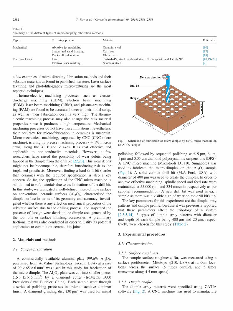
Table 1Summary of the different types of micro-dimpling fabrication methods.
Type Texturing process Material Reference
Mechanical Abrasive jet machining Ceramic, steel [10]Shaper and sand blasting Cast iron [17]Rockwell indentation Glass disc [18]
Thermo-electric Laser Ti–6Al–4V, steel, hardened steel, Ni composite and Cr18Ni9Ti [10,19–21]Electrox laser marking Stainless steel [2]
Fig. 1. Schematic of fabrication of micro-dimple by CNC micro-machine onan Al2O3 sample.
T. Roy et al. / Ceramics International 40 (2014) 2381–23882382
a few examples of micro-dimpling fabrication methods and theirsubstrate materials as found in published literature. Laser surfacetexturing and photolithography micro-texturing are the mostreported techniques.
Thermo-electric machining processes such as electro-discharge machining (EDM), electron beam machining(EBM), laser beam machining (LBM), and plasma-arc machin-ing (PAM) are found to be accurate; however, their initial setup,as well as, their fabrication cost, is very high. The thermo-electric machining process may also change the bulk materialproperties since it produces a high temperature. Mechanicalmachining processes do not have these limitations; nevertheless,their accuracy for micro-fabrication in ceramics is uncertain.Micro-mechanical machining, supported by CNC (CNC micromachine), is a highly precise machining process (71% micronerror) along the X, Y and Z axes. It is cost effective andapplicable to non-conductive materials. However, a fewresearchers have raised the possibility of wear debris beingtrapped in the dimple from the drill bit [22,23]. This wear debrismight not be biocompatible, therefore introducing risk to theimplanted prosthesis. Moreover, finding a hard drill bit (harderthan ceramic) with the required specification is also a keyconcern. So far, the application of the CNC micro machine isstill limited to soft materials due to the limitations of the drill bit.In this study, we fabricated a well-defined micro-dimple surfaceon conventional ceramic surfaces (Al2O3), characterised thedimple surface in terms of its geometry and accuracy, investi-gated whether there is any effect on mechanical properties of thesubstrate surface due to the drilling process, and inspected thepresence of foreign wear debris in the dimple area generated bythe tool bits or surface finishing accessories. A preliminaryfrictional test was also conducted in order to justify its potentialapplication to ceramic-on-ceramic hip joints.
2. Materials and methods
2.1. Sample preparation
A commercially available alumina plate (99.6% Al2O3,purchased from AdValue Technology Tucson, USA) at a sizeof 90� 65� 6 mm3 was used in this study for fabrication ofthe micro-dimple. The Al2O3 plate was cut into smaller pieces(15� 15� 6 mm3) by a diamond cutter (IsoMets 5000Precisions Saws Buehler, China). Each sample went througha series of polishing processes in order to achieve a mirrorfinish. A diamond grinding disc (30 μm) was used for initial
polishing, followed by sequential polishing with 9 μm, 6 μm,1 μm and 0.05 μm diamond polycrystalline suspensions (DPS).A CNC micro machine (Mikrotools DT110, Singapore) wasused to fabricate the micro-dimples on the Al2O3 sample(Fig. 1). A solid carbide drill bit (M.A Ford, USA) withdiameter of 400 μm was used to create the dimples. In order toachieve effective machining, spindle speed and feed rate weremaintained at 55,000 rpm and 334 mm/min respectively as persupplier recommendation. A new drill bit was used in eachsample as there was a visible sign of wear on the drill bit's tip.The key parameters for this experiment are the dimple array
patterns and dimple profile, because it was previously reportedthat these parameters affect the tribology of a system[2,3,5,14]. 3 types of dimple array patterns with diameterand depth of each dimple being 400 μm and 20 μm, respec-tively, were chosen for this study (Table 2).
3. Experimental procedures
3.1. Characterisation
3.1.1. Surface roughnessThe sample surface roughness, Ra, was measured using a
surface profilometer (Mitutoyo sj210, USA), at random loca-tions across the surface (5 times parallel, and 5 timestransverse along 4.5 mm spans).
3.1.2. Dimple profileThe dimple array patterns were specified using CATIA
software (Fig. 2). A CNC machine was used to manufacture

T. Roy et al. / Ceramics International 40 (2014) 2381–2388 2383
the dimples. Scanning electron microscopy (SEM; AURIGA,Zeiss Singapore) was used to confirm the morphology of thedimple array patterns (Fig. 3a). The diameter and the pitch(distance between 2 dimples) were measured with an opticalmicroscope (Olympus BX51, Japan). Analysis software byOlympus, Japan, was used to measure the diameter and pitchof the dimple. Basically, a region of interest (ROI) wasselected, and the software calculated the diameter. A digitalruler within the software was used to measure the distance.The depth of the dimple was measured by a surface profil-ometer (Mitutoyo sj210, USA). This is a stylus type ofprofilometer, and being tapped across the surface of thedimple, it produces a measurement along the X and Y axes.The reading from the Y axis will be used to calculate the heightof the dimple (Fig. 3b). The X reading can be used to confirmthe diameter of the dimple which was measured previously byan optical microscope. Each sample has 2 replicates.
Friedrich [23] mentioned the possible surface integritycaused by the cutting process, and unexpected wear debris(chips) generated which may not be completely removed fromthe dimple. Therefore, samples were washed with 10%sulphuric acid, distilled water and ultrasonic cleaner, and thentested with X-ray diffraction (XRD; Philips X′pert MPDPW3040, Singapore) and EDS (SEM; Philips XL40). TheXRD pattern of the sample was then compared to that of Al2O3
(JCPDS card 46-0306). EDS was then employed to determinethe presence of any other foreign particles.
3.2. Mechanical properties
3.2.1. HardnessVickers indentation (Mitutoyo AVK-C2, USA) technique
was used to measure hardness, fracture toughness and resi-dual stress. A 2 kg load was loaded on to the dimple and
Table 2Dimple parameters.
Dimple arraypattern
Dimplediameter (μm)
Dimple distance/pitch (mm)
Dimpledepth (μm)
Dimple areadensity (%)
Pattern 1 400 2 20 5.84Pattern 2 400 1.5 20 9.78Pattern 3 400 1 20 19.63
Fig. 2. A drawing of the 3 dimple array patterns. The dimple array pattern is arran2 mm, (b) in pattern 2, the distance between 2 dimples is 1.5 mm, and (c) in patte
non-dimple surface area for 15 s. The length of the diagonaland crack produced by indenter is shown in Fig. 4. Threerandom dimples and non-dimple areas were selected for thehardness test. These procedures were repeated on everysample.
3.2.2. Fracture toughness (KIC)The fracture toughness (KIC) was calculated from the length
of cracks (Fig. 4) induced by the indenter using the equation[24,25]
KIC ¼ 0:016E
H
� �1=2 P
C3=2
� �ð1Þ
where KIC is the indentation fracture toughness (Paffiffiffiffim
p),
0.016 is the material-independent constant for a Vickers radialcrack, E is Young's modulus (MPa), H is the Vickers hardness(GPa), P is the indentation load (N), and C is the half-length ofthe radial cracks parallel to the layers on the surface (m). The
value of 0.016 EH
� �1=2was estimated at 0.07, which is a typical
value for Al2O3 ceramics.
3.2.3. Residual stressResidual stresses within the dimple surface were also
calculated by indentation methods. In low surface tensionconditions, cracks perpendicular to the layers (CR) weredetermined by the stress intensity factor for the crack understress. The indentation fracture toughness (KIC) was related totwo factors; the first was the stress intensity factor for the crackunder stress (KI), which caused deformation of the area byindentation, and the second was residual stress represented byKR:
KIC ¼ KIþKR ð2Þ
KR ¼ YsRCR1=2 ð3Þ
where Y is a geometric factor, approximately 1.26, sR is theresidual stress, and (CR) is the crack perpendicular to the layer.The residual stress on both sides of the crack was the same,whereas this was not the case in the field gradient. The valuesrecorded indicated that the residual stresses were at the centreof the indentation. The stress was tensile when sR40 andcompressive when sRo0:
ged in a rectangular pattern. (a) In pattern 1, the distance between 2 dimples isrn 3, the distance between 2 dimples is 1 mm.

100 µm
Dep
th
0.5 1.50.0 1.0 2.0 2.5 3.0 3.5 4.0 4.5
0.0-5.0
-10.0-15.0-20.0-25.0
5.0
Distance (mm)
Hei
ght (
µm)
Fig. 3. (a) A SEM image shows the micrograph of pattern 2 surface, and (b) dimple profiles were mapped by the profilometer where their depths are shown by thered arrow. (For interpretation of the references to colour in this figure legend, the reader is referred to the web version of this article.)
Fig. 4. Crack indentation definition by Vickers indenter.
T. Roy et al. / Ceramics International 40 (2014) 2381–23882384
sR ¼ KIC�KI
YCR1=2
¼KIC 1� C
CR
� �3=2
YCR1=2
ð4Þ
The main difficulty involved in measuring hardness within thedimple is dealing with the curved surface. Since the 3D topographyfor a dimple is similar to a semispheroid, measurement error isunavoidable. To minimise the experimental error the Vickersindenter was chosen as it has a better stability when dealing withcurved surfaces than do other common indenter types.
3.3. Friction testing
Friction tests were conducted by a pin-on-disk tester (Fig. 5)where the disk (flat surface) and pin (cylindrical surface) wererubbing each other. The disks had three surface profiles: non-dimple, pattern 1 and pattern 2 which were investigated underbovine calf serum. The pin was placed into a metallic holder
(zero degree of freedom), and the holder had 10 mm/s speed(simulated medium walking speed 10 mm/s) and was loadedunder 10 N, 15 N, 20 N. Details of experiment parameters areshown in Table 3. The sliding contact zone was fully soaked ina lubricant where the temperature was kept at 37 1C through-out the tests.Friction coefficients were calculated using the friction force
measured at different loading conditions. Total running time ofevery sample was 90 min—first 30 min under 10 N, next30 min under 15 N, and last 30 min under 20 N. These loadswere estimated to create the Hertzian contact pressure of 0.132,0.162, and 0.187 GPa correspondingly.
4. Result and discussion
4.1. Surface roughness
Prior to the fabrication of the dimples, the sample Ra wasmeasured. The average surface roughness (Ra) of six sampleswas 0.1270.02 mm, indicating that the prepared samples havea smooth surface. The very small standard error measurementof the 6 samples shows that almost all the samples have thesame surface roughness.
4.2. Dimple profile
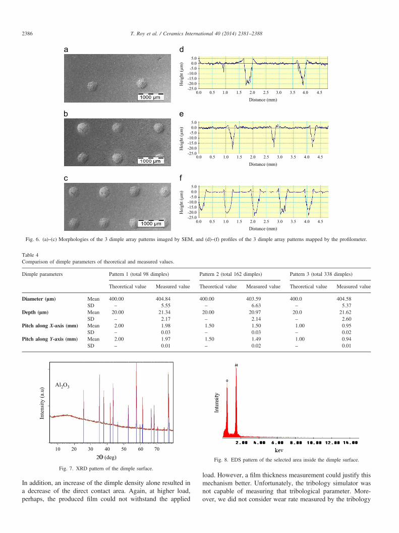
The morphologies of the dimple array patterns were con-firmed by SEM images (Fig. 6). Table 4 summarises themeasured and theoretical values of the dimple diameter, depthand pitch along X and Y. It shows that measured andtheoretical values are very close and the standard deviationis very small in all cases. This confirms that the CNC micromachine can be used to produce micro-dimples with accuracy.The tribology of a system depends on the diameter, depth and

Fig. 5. (a) Schematic diagram of the test setup and (b) tribometer.
Table 3Parameters of friction test.
Pin and disc Alumina ceramic
Load (N) 10, 15, 20Hertz contact pressure (GPa) 0.132, 0.162, 0.187Sliding velocity (mm/s) 10Stroke length (mm) 2Lubricant Bovine synovial fluidTemperature (1C) 37
T. Roy et al. / Ceramics International 40 (2014) 2381–2388 2385
pitch distance [14,19,22]; hence we needed to make sure theselected parameters are reproducible. The ability of the CNCmicro machine to control accurate replication of dimpleparameters allows the production of a high quality dimplesurface.
4.3. Debris
The results of the wear debris (chips) tests were likewisesupportive of the manufacture method. The XRD pattern fromthe cleaned sample is shown in Fig. 7, which coincides withthat of aluminium oxide in the JCPDS card of 46-0306. Basedon the XRD result, there is no other foreign particle found onthe surface of the sample. The EDS pattern also showed noother foreign particle inside the dimple in Fig. 8.
4.4. Mechanical properties
Mechanical testing including hardness, toughness and resi-dual test was performed in view of the brittleness properties ofthe ceramic. A pile-up region was observed on the outer edgeof the dimple, a phenomenon often associated with tensilestress and a negative influence on tribological properties. As aresult of the pile-up regions, compressive residual stresses areformed on the material subsurface. Micro-machining does notaffect the hardness within the dimple area. The averagehardness within the dimple area was slightly lower than theaverage value of the non-dimple area. This could be explainedby the presence of compressive stress within the dimplesurface. On average, hardness in the dimple area decreased
13% compared to the bulk material. Fig. 9 presents thehardness profile of the surface for different patterns. As thedimple depth is 20 μm, the slope of the dimple is nearlyperpendicular to the surface.The fracture toughness of the dimple surfaces at the applied
indentation load of 2 kg is shown in Fig. 10. At the centre ofthe dimple the fracture toughness was as low as 3.9 MPa
ffiffiffiffim
pincreasing at the periphery of the dimple, where fracturetoughness on the non-dimple surface averaged to 6.5 MPaffiffiffiffim
p. As compressive load was applied during the drilling
process at the centre of the dimple, fracture toughness is lessthere than in the non-dimple surface areas. Fig. 11 shows thatcompressive residual stress forms at the centre of the dimple,but near the periphery of the dimple diameter there is tensileresidual stress due to the pile-up region, as expected. It isexpected that tensile residual stress creates the premises forcrack initiation and crack growth. On the other hand, com-pressive residual stresses on the surface act on surface integrityby closing crack tips and resisting crack growth [26]. At thedimple centre the residual stresses were measured at 385, 381and 376 MPa (compressive) whereas near the pile-up regionthe residual stresses were measured at 150, 201 and 173 MPa(tensile).
4.5. Friction test
The friction coefficient profiles for non-dimple, and patterns1 and 2 are shown in the Fig. 12. The average frictioncoefficient (m) trends were found to be as follows:mpattern 2ompattern 1omnon-dimpleAt load 10 N (132 Mpa), the
performance of dimple surface was very significant—thepercentage of friction coefficient reduction 15.2% to pattern2 and 9.1% to pattern 1 compared to non-dimple surface.However, the difference of friction coefficient became flatter atthe higher load 20 N (187 Mpa)—percentage of frictioncoefficient reduction 3.6% to the pattern 2 and 3.2% to pattern1 compared to non-dimple surface. Although both dimplesurfaces (Patterns 1 and 2) showed good friction reduction, italso revealed that the micro-dents with higher area densityperformed better in reducing friction. This might be becausethe higher density dimple area had better fluid reservationand promoted the retention of a thicker lubricating film.
5.0
Hei
ght (
µm) 0.0
-10.0
-20.0
Distance (mm)0.0
-5.0
-15.0
-25.00.5 1.0 1.5 2.0 2.5 3.0 3.5 4.0 4.5
5.00.0
-5.0-10.0-15.0
-25.0-20.0H
eigh
t (µm
)5.00.0
-10.0
-25.0-20.0
-5.0
-15.0
Hei
ght (
µm)
Distance (mm)
Distance (mm)
0.0 0.5 1.0 1.5 2.0 2.5 3.0 3.5 4.0 4.5
4.54.03.53.02.52.01.51.00.50.0
Fig. 6. (a)–(c) Morphologies of the 3 dimple array patterns imaged by SEM, and (d)–(f) profiles of the 3 dimple array patterns mapped by the profilometer.
Table 4Comparison of dimple parameters of theoretical and measured values.
Dimple parameters Pattern 1 (total 98 dimples) Pattern 2 (total 162 dimples) Pattern 3 (total 338 dimples)
Theoretical value Measured value Theoretical value Measured value Theoretical value Measured value
Diameter (lm) Mean 400.00 404.84 400.00 403.59 400.0 404.58SD – 5.55 – 6.63 – 5.37
Depth (lm) Mean 20.00 21.34 20.00 20.97 20.0 21.62SD – 2.17 – 2.14 – 2.60
Pitch along X-axis (mm) Mean 2.00 1.98 1.50 1.50 1.00 0.95SD – 0.03 – 0.03 – 0.02
Pitch along Y-axis (mm) Mean 2.00 1.97 1.50 1.49 1.00 0.94SD – 0.01 – 0.02 – 0.01
Inte
nsity
(a.u
)
2 (deg)10 20 30 40 60 7050
Al2O3
Fig. 7. XRD pattern of the dimple surface.
Fig. 8. EDS pattern of the selected area inside the dimple surface.
T. Roy et al. / Ceramics International 40 (2014) 2381–23882386
In addition, an increase of the dimple density alone resulted ina decrease of the direct contact area. Again, at higher load,perhaps, the produced film could not withstand the applied
load. However, a film thickness measurement could justify thismechanism better. Unfortunately, the tribology simulator wasnot capable of measuring that tribological parameter. More-over, we did not consider wear rate measured by the tribology

Fig. 9. Vickers hardness for the dimple surface with load 2 kg.
Fig. 10. Indentation fracture toughness for the dimple surface.
Fig. 11. Residual stress measured by the indentation method for the dimplingsurface.
Fig. 12. Friction coefficients for different samples at 10 N, 15 N, and20 N loads.
T. Roy et al. / Ceramics International 40 (2014) 2381–2388 2387
simulator since it was affected by the wear debris. However thereduction of friction coefficient is justified by other similarpublished studies, although they were conducted on othermaterial combinations [13,27,28].
Despite these limitations, realistic simulated hip joints experi-ment conditions were maintained. These parameters are: (1) bovinesynovial fluid, which was collected from four joints of a cow [29];(2) loads of 10, 15, 20 N (Hertz pressure 132, 162, 187 MPa)
which are similar to those of other published articles for ceramic-on-ceramic hip joints [30]; (3) speed of 10 mm/s which issimulated medium walking speed [31]; (4) 37 1C temperaturewhich is body temperature [29]; and (5) a very smooth surface (Ra0.12 μm) [13].
5. Conclusion
A successful fabrication of micro-dimple array on Al2O3
surfaces revealed the feasibility of applying micro-tools onceramic surfaces. The key findings of this research are asfollows:
i.
Micro-tooling is a reliable process for fabricating micro-dimple arrays with different geometries on ceramic sur-faces. The dimple parameters were precisely characterised(diameter, depth, pitch along X-axis, pitch along Y-axis),each with standard deviation as low as 3.75%.ii.
The hardness was found to be 9.8% and 2.5% lower at theinner edge and centre of the dimple respectively, comparedto the non-dimple area. Moreover, the centre of the dimplewas found to have a lower toughness compared to the inneredge and non-dimple area. The induced residual stress wascompressive (380.67 MPa) at the centre of the dimple.iii.
There was no detectable wear debris nor were there cuttingchips found in the dimple holes.iv.
Friction test confirmed the influence of dimple surface insignificantly reducing friction coefficient at 10–20 N loadsunder simulated hip joint conditions. A further tribologicalexperiment with wide ranges of dimple parameters onoptimising dent surfaces to ceramic on ceramic hip jointsbased on their outcomes on friction, wear rate and loadcarrying capacity is under investigation.Acknowledgements
The research was supported by University of MalayaResearch Grant (UMRG; RG147-12AET) and Ministry ofHigher Education High ImpactResearch Grant (UM.C/HIR/MOHE/ENG/44).
References
[1] H.S.A. Rahman, D. Choudhury, N.A.A. Osman, H.N. Shasmin,W.A.B.W. Abas, In vivo and in vitro outcomes of alumina, zirconiaand their composited ceramic-on-ceramic hip joints, Journal of theCeramic Society of Japan 121 (4) (2013) 382–387.
[2] Y. Qiu, M. Khonsari, Experimental investigation of tribological perfor-mance of laser textured stainless steel rings, Tribology International 44(5) (2011) 635–644.
[3] S. Qian, D. Zhu, N. Qu, H. Li, D. Yan, Generating micro-dimples arrayon the hard chrome-coated surface by modified through mask electro-chemical micromachining, The International Journal of Advanced Man-ufacturing Technology 47 (9–12) (2010) 1121–1127.
[4] W. Huang, L. Jiang, C. Zhou, X. Wang, The lubricant retaining effect ofmicro-dimples on the sliding surface of PDMS, Tribology International (2012).

T. Roy et al. / Ceramics International 40 (2014) 2381–23882388
[5] A. Kovalchenko, O. Ajayi, A. Erdemir, G. Fenske, I. Etsion, The effect of lasersurface texturing on transitions in lubrication regimes during unidirectionalsliding contact, Tribology International 38 (3) (2005) 219–225.
[6] F. Meng, T. Davis, J. Cao, Q.J. Wang, D. Hua, J. Liu, Study on effect ofdimples on friction of parallel surfaces under different sliding conditions,Applied Surface Science 256 (9) (2010) 2863–2875.
[7] X. Wang, K. Kato, K. Adachi, K. Aizawa, Loads carrying capacity mapfor the surface texture design of SiC thrust bearing sliding in water,Tribology International 36 (3) (2003) 189–197.
[8] M.-s. Suh, Y.-h. Chae, S.-s. Kim, T. Hinoki, A. Kohyama, Effect ofgeometrical parameters in micro-grooved crosshatch pattern under lubricatedsliding friction, Tribology International 43 (8) (2010) 1508–1517.
[9] X. Wang, W. Liu, F. Zhou, D. Zhu, Preliminary investigation of the effectof dimple size on friction in line contacts, Tribology International 42 (7)(2009) 1118–1123.
[10] M. Wakuda, Y. Yamauchi, S. Kanzaki, Y. Yasuda, Effect of surfacetexturing on friction reduction between ceramic and steel materials underlubricated sliding contact, Wear 254 (3) (2003) 356–363.
[11] D. Choudhury, R. Walker, A. Shirvani, R. Mootanah, The influences ofhoned surfaces on metal-on-metal hip joints, Tribology Online 8 (3)(2013) 195–202.
[12] D. Choudhury, R. Walker, T. Roy, S. Paul, R. Mootanah, Performance ofhoned surface profiles to artificial hip joints: an experimental investiga-tion, International Journal Of Precision Engineering And Manufacturing(2013) (in press).
[13] H. Sawano, S.i. Warisawa, S. Ishihara, Study on long life of artificialjoints by investigating optimal sliding surface geometry for improvementin wear resistance, Precision Engineering 33 (4) (2009) 492–498.
[14] L. Gao, P. Yang, I. Dymond, J. Fisher, Z. Jin, Effect of surface texturingon the elastohydrodynamic lubrication analysis of metal-on-metal hipimplants, Tribology International 43 (10) (2010) 1851–1860.
[15] P. Shum, Z. Zhou, K. Li, To increase the hydrophobicity and wearresistance of diamond-like carbon coatings by surface texturing usinglaser ablation process, Thin Solid Films (2013) (in press).
[16] X.J. Jiang, D.J. Whitehouse, Technological shifts in surface metrology,CIRP Annals—Manufacturing Technology 61 (2) (2012) 815–836.
[17] M. Nakano, A. Korenaga, A. Korenaga, K. Miyake, T. Murakami,Y. Ando, H. Usami, S. Sasaki, Applying micro-texture to cast ironsurfaces to reduce the friction coefficient under lubricated conditions,Tribology Letters 28 (2) (2007) 131–137.
[18] I. Křupka, M. Hartl, The effect of surface texturing on thin EHDlubrication films, Tribology International 40 (7) (2007) 1100–1110.
[19] T. Hu, L. Hu and Q. Ding, Effective solution for the tribologicalproblems of Ti–6Al–4V: combination of laser surface texturing andsolid lubricant film, Surface and Coatings Technology 206 (24) (2012),5060–5066.
[20] A. Kovalchenko, O. Ajayi, A. Erdemir, G. Fenske, Friction and wearbehavior of laser textured surface under lubricated initial point contact,Wear 271 (9) (2011) 1719–1725.
[21] J. Li, D. Xiong, H. Wu, Y. Zhang and Y. Qin, Tribological properties oflaser surface texturing and molybdenizing duplex-treated stainless steel atelevated temperatures, Surface and Coatings Technology 228, Supple-ment 1, (2012), S219–S223.
[22] Y. Guo, R. Caslaru, Fabrication and characterization of micro dent arraysproduced by laser shock peening on titanium Ti–6Al–4V surfaces,Journal of Materials Processing Technology 211 (4) (2011) 729–736.
[23] C. Friedrich, Micromechanical machining of high aspect ratio prototypes,Microsystem Technologies 8 (4–5) (2002) 343–347.
[24] S. Gustafsson, L.K.L. Falk, E. Lidén, E. Carlström, Pressureless sinteredAl2O3–SiC nanocomposites, Ceramics International 34 (7) (2008)1609–1615.
[25] E. Askari, M. Mehrali, I. Metselaar, N. Kadri, M.M. Rahman, Fabricationand mechanical properties of functionally graded material by electro-phoretic deposition, Journal of the Mechanical Behavior of BiomedicalMaterials (2012).
[26] Y.B. Guo, R. Caslaru, Fabrication and characterization of micro-dentarrays produced by laser shock peening on titanium Ti–6Al–4V surfaces,Journal of Materials Processing Technology 211 (4) (2011) 729–736.
[27] H. Ito, K. Kaneda, T. Yuhta, I. Nishimura, K. Yasuda, T. Matsuno,Reduction of polyethylene wear by concave dimples on the frictionalsurface in artificial hip joints, The Journal of Arthroplasty 15 (3) (2000)332–338.
[28] C. Myant, R. Underwood, J. Fan, P. Cann, Lubrication of metal-on-metalhip joints: the effect of protein content and load on film formation andwear, Journal of the Mechanical Behavior of Biomedical Materials 6(2012) 30–40.
[29] V.C. Mow, R. Huiskers, Basic Orthopaedic Biomechanics and Mechano-Biology, Lippincott Williams & Wilkins, 2005.
[30] L. Mattei, F. Di Puccio, B. Piccigallo, E. Ciulli, Lubrication and wearmodelling of artificial hip joints: a review, Tribology International 44 (5)(2011) 532–549.
[31] G. Bergmann, G. Deuretzbacher, M. Heller, F. Graichen, A. Rohlmann,J. Strauss, G. Duda, Hip contact forces and gait patterns from routineactivities, Journal of Biomechanics 34 (7) (2001) 859–871.