fabrication and characterization of affordable hydrophobic ... · kaolin–alumina ceramic material...
TRANSCRIPT
Journal of Advanced Ceramics 2017, 6(4): 330–340 ISSN 2226-4108https://doi.org/10.1007/s40145-017-0245-1 CN 10-1154/TQ
Research Article
www.springer.com/journal/40145
Fabrication and characterization of affordable hydrophobic ceramic
hollow fibre membrane for contacting processes
Mohammed Abdulmunem ABDULHAMEEDa,b, Mohd Hafiz Dzarfan OTHMANa,*, Haider Nadhom Azziz Al JODAb, Ahmad Fauzi ISMAILa, Takeshi MATSUURAc, Zawati HARUNd, Mukhlis A. RAHMANa, Mohd Hafiz PUTEHe, Juhana JAAFARa
aAdvanced Membrane Technology Research Centre (AMTEC), Faculty of Chemical and Energy Engineering, Universiti Teknologi Malaysia, 81310 UTM Johor Bahru, Johor, Malaysia
bDepartment of Petroleum and Petrochemical Engineering, Engineering College, Kerbala University, 56001 Kerbala, Iraq
cDepartment of Chemical and Biological Engineering, University of Ottawa, Ottawa, Ontario, K1N 6N5, Canada dAdvanced Manufacturing & Materials Centre (AMMC), Faculty of Mechanical and Manufacturing Engineering,
Universiti Tun Hussein Onn Malaysia, Parit Raja, 86400 Batu Pahat, Johor, Malaysia eDepartment of Environmental Engineering, Faculty of Civil Engineering, Universiti Teknologi Malaysia, 81310
UTM Johor Bahru, Johor, Malaysia
Received: April 26, 2017; Revised: August 26, 2017; Accepted: September 01, 2017 © The Author(s) 2017. This article is published with open access at Springerlink.com
Abstract: Affordable hydrophobic hollow fibre membranes were prepared using kaolin and alumina based ceramic powders via a combined phase inversion and sintering technique, followed by a grafting with fluoroalkylsilane (FAS). The crux of the matter in this paper is to study the changes in the properties of the hollow fibre membranes (gas permeation, mechanical strength, pore size, porosity, tortuosity, morphology, and contact angle) by the addition of alumina (Al2O3) to the pure kaolin with mono or multiparticle sizes. By varying the overall loading and particle size of alumina addition, different morphologies of the membranes were obtained due to the differences in the path lengths during phase inversion process for each solvent and nonsolvent exchange. The successful grafting with FAS was evidenced by the increase in contact angle from nearly equal to zero degree before grafting to 140° after grafting. Kaolin–alumina-4, one of the hollow fibres fabricated in this work, achieved a mean pore size of 0.25 µm with the bending strength of 96.4 MPa and high nitrogen permeance of 2.3×10⁵ mol·m2·Pa1·s1, which makes the hollow fibre most suitable for the membrane contactor application.
Keywords: ceramic membrane contactor; hollow fibre; kaolin; hydrophobic
1 Introduction
The quality of the ceramic membrane may be much
better than other membrane material, especially polymers, owing to its superior chemical and thermal stability and ability to withstand harsh operating conditions (temperature and chemicals) [1]. For many years, an enormous number of studies have been conducted on hollow fibre membranes due to their
*Corresponding author. E-mail: [email protected], [email protected]

J Adv Ceram 2017, 6(4): 330–340
www.springer.com/journal/40145
331
exceptionally high packing density compared to other geometrical shapes, such as flat sheet and tubular. In addition, the hollow fibre possesses a small wall thickness with less resistance to the fluid flow [2].
Currently, the engineering community is paying significant attention to the request for technologies that would lead us to the target of technological sustainability. A promising example with a huge interest by engineers is the membrane contactor. The development of effective and less expensive membranes for membrane contactor application has become increasingly important. Membrane contactors represent a technology where porous membranes are used as “packing materials” for interphase mass transfer and offer superior process efficiency compared to the more traditional separation process. The membrane contactors are able to carry out all traditional gas separation (stripping and absorption, distillation, liquid–liquid extraction) as well as emulsification, crystallisation [3] with reduced operational and capital costs owing to their high interfacial area per volume and the unique functions of the membrane.
The crucial requirements of membrane contactor include appropriate hydrophobicity/hydrophilicity and high porosity so that one fluid is prevented from penetrating into the pores while the other fluid is allowed to enter into the pores easily [3,4]. Since the membrane materials play an essential role in governing the fluid transport through the membrane, there is a need to judiciously select the membrane materials to fulfil the above requirements. Presently, most of the commercially and in-house made hollow fibre membranes are made from polymeric materials such as, but not limited to, polyvinylidene fluoride (PVDF), polypropylene (PP), polyethylene (PE), polyimide, and polysulfone [5,6]. A considerable amount of reports are found in the literature on the morphological changes of polymeric membranes after having been in contact with organic fluids for a certain length of time. For the adsorbent, a highly alkaline aqueous solution or an amine solution is usually used; however, the membrane is wetted or the chemical used in the solution ultimately causes permanent damage of the membrane, leading to the need of frequent replacement. For example, it was found that the performance of polymeric membrane contactors completely stopped after a couple weeks of operation due to the membrane wetting [7]. In contrast, ceramic materials have much better durability due to their superior chemical and thermal stability.
Ceramic hollow fibre membranes have been recently
used for membrane contactor applications after some modification [8–11]. Ceramic membrane is hydrophilic in nature owing to the O–H group on the membrane surface [12]. Hence in order to make the membrane surface hydrophobic, the chemical modification needs to be applied. Flouroalkylsilanes (FASs) are the group of compounds that can be effectively used to create the hydrophobic character of different surfaces. The grafting process can be performed by reaction between –OH groups of the ceramic material and ethoxy groups (O-Et) presented in organosilane compounds. Many literature reviews have reported on the grafting of different FAS on the surface of alumina, titania, zirconia, and silica. Unfortunately, these materials are expensive and/or need high sintering temperatures; therefore a new material has been recently proposed to lower the ceramic membrane cost and make it more affordable. Kaolin clay based ceramic material is one of the promising alternatives to alumina due to the various advantages such as inexpensiveness and low sintering temperature. Although a large amount of information about the use of kaolin as ceramic membrane material has been disclosed in the open literature [13–15], the fabrication of kaolin membrane by the phase inversion technique has been rarely reported. One of the reasons may be due to the low density of kaolin. The kaolin powders have a low density of 2.4 g/cm3 compared to alumina with a density of 3.95 g/cm3. Hence, the relatively low density of kaolin powders is able to create resistance in preparing dope when mixing them with the solvent and binder especially when exceeding more than 50 wt%. The optimal ceramic content in the dope is 50–60 wt% [16] in order to fabricate well-structured membranes with small pore sizes and a narrow pore size distribution. To overcome this problem, alumina particles of various sizes were added to reach the desired total ceramic powder loading. Alumina is suitable as an additive due to its compatibility with kaolin during the sintering process. The sintering reaction may also take place between kaolin and alumina to produce the mullite. The formation of kaolin–alumina ceramic material is also beneficial since it can be produced from relatively low-cost materials and at lower sintering temperatures than pure alumina. Recently, the distinctive properties of mullite such as high thermal and mechanical strength, and outstanding stability under harsh chemical environments made it a strong candidate material for advanced structural and functional ceramics [17]. As well, the structure of metal oxides such as alumina allows for the surface

J Adv Ceram 2017, 6(4): 330–340
www.springer.com/journal/40145
332
modification. For instance, a maximum contact angle of 120° was reached by the modification of alumina hollow fibre membrane [12]. Surface modification of yittria-stabilized zirconia (YSZ) was possible after pre-treatment of the surface [18]. Yu et al. [8] developed alumina tube by coating the surface with ZrO2 layer in order to increase the hydrophobicity.
In the present study, we are interested in preparing hydrophobic membrane that may carry the essential ingredient of the membrane such as high permeability and sufficient mechanical strength, that would permit us to leave the door open to have a certain flexibility to choose a potential application for each membrane prepared.
Our previous work showed that the ceramic membrane contactors made from kaolin/alumina mixture could be used for CO2 absorption [10]. The objective of this study is to show that the kaolin/alumina membranes can also be used for many other applications such as membrane distillation, osmotic evaporation, and filtration especially by changing the ratio of alumina, of mono or multiparticle sizes, to kaolin. Thus, it is aimed in this work to explore a new material from which affordable membranes of sufficiently high permeability, high mechanical strength, high hydrophobicity, and narrow pore size distribution can be fabricated. Besides, the main purpose of this study is also to improve hydrophobicity on the membrane surface by observing the effect of the above factors towards fulfilling the required application as the membrane contactor materials.
2 Experimental
2. 1 Materials
Local kaolin with particle sizes of 2–4 µm purchased
from KAOLIN (MALAYSIA) SDN. BHD, and alumina oxide with three different particle sizes of 1, 0.05, and 0.02 µm purchased from Alfa AESAR, A Johnson Mathy Company, were used as the base materials, and Arlacel P135 (polyethyleneglycol 30-dipolyhydroxystearate, Uniqema) was used as dispersion. N-methyl-2-pyrrolidinone (NMP) procured from Merck and PESf (RADEL A-300 supplied by Amoco Chemicals) were used as the solvent and polymer binder respectively. Tap and distilled water were used as the coagulant in the spinning process. Hexane (A grade, Sigma-Aldrich) and Fluoroalkylsilanes (FASs) (Manchester Organics) were used for surface grafting.
2. 2 Fabrication of precursor hollow fibre membranes
Figure 1 shows the steps involved in the preparation of hollow fibre membrane precursors from kaolin and kaolin/alumina. Table 1 shows the dope compositions used to prepare hollow fibre membranes. The ceramic hollow fibres were prepared via immersion-induced phase inversion/sintering technique. The details of both experimental setup and procedure are given elsewhere [9]. A predetermined quantity of Arlacel P135 was added to NMP as a dispersant under gentle stirring prior to the addition of ceramic powders. The dispersion was obtained with different proportions of alumina and/or kaolin in a way that the final composition of the precursor hollow fibre remained with 0, 25, 26.5, and 27.5 wt% of alumina (Table 1). The ceramic powders were added into the solution with a mechanical stirring at a suitable speed. The suspension was then rolled/milled at 150 rpm for 48 h. PESf was then added to the suspension and continuously milled for another 48 h. As a last step before the extrusion, the dope suspension was degassed under vacuum with gentle stirring at room temperature until bubbles were no
Fig. 1 Preparation of affordable kaolin–alumina hollow fibres using phase inversion and sintering techniques.

J Adv Ceram 2017, 6(4): 330–340
www.springer.com/journal/40145
333
longer visible. The dope was transferred into a stainless steel
container and extruded by a syringe pump (PHD 2000, Harvard Apparatus) at constant flow rate of 8 mL/min through a tube-in-orifice spinneret into an external water coagulation bath and kept there overnight to complete the phase inversion. The tube-in-orifice spinneret had an outer dimeter of 3 mm and inner diameter of 1.5 mm. In order to run the extrusion process smoothly, the air gap was kept constant at 4.5 cm. Higher air gap distance would result in the flow instability of the dope suspension due to the high viscosity of the dope. The precursor hollow fibres so obtained were thoroughly washed with water. The composition of the spinning dope is given in Table 1.
2. 3 Sintering process
The precursor was sintered in a high-temperature tubular furnace (XY-1700 MAGNA) to consolidate the precursor into a strong hollow fibre. The temperature was first raised from room temperature to 600 ℃ at a rate of 2 ℃/min and maintained for 2 h in order to remove the residual liquid, organic binders, and dispersant. Then, the furnace was heated up to the target temperature (1400 ℃) at a rate of 5 ℃/min and maintained for 6 h. Lastly, the furnace was cooled down to room temperature at a cooling rate of 5 ℃/min. The hollow fibre code given in the table is also applicable to the hollow fibre after surface grafting.
2. 4 Characterization
The membranes were characterised by contact angle measurement, scanning electron microscopy (SEM), gas permeation test, mercury porosimetry, and the three-point bending method for measuring the mechanical strength. For SEM characterization, samples were broken carefully to make a smooth cross-sectional surface prior to gold coating under vacuum. SEM images at various magnifications were taken using the equipment (TM 3000, Hitachi). The porosity, tortuosity, and pore size distribution were
measured using mercury intrusion (Micromeritics, Autopore IV, 9500). Nitrogen gas permeation test was conducted at feed pressures of 0.1 and 0.5 bar gauge using a module in which fibres were installed in a stainless-steel holder with one end of the fibres sealed by epoxy resin. Figure 2 is the experimental setup for the measurement of gas permeability. The operating pressure can be read from the HDI 2000B digital pressure gauge. The hollow fibers were glued with epoxy glue at one end and the other end was potted to a stainless steel fitting. The gas permeance was determined using Eq. (1):
o i
o i
ln( / )π ( )
Q D DJL D D p
(1)
where J is the nitrogen gas permeability (mol·m2·Pa1·s1), Q is the N2 permeation rate (mol/s), L is the effective length of hollow fibre (m), and p is the transmembrane pressure difference (Pa). oD and
iD are the outer and inner diameters of the hollow fibre (m), respectively. Each of oD and iD was determined by SEM.
The bending strength of the sintered hollow fibres was measured by the three-point bending method using an Instron Model 5544 tensile tester. The loading cell was 1 kN. The bending strength ( F (N·m2)) was calculated by Eq. (2):
o
4 4o i
8πF
FLDD D
(2)
where F is the force value when the fracture occurs (N),
Fig. 2 Schematic diagram of apparatus for measuring gas permeation: (a) flow diagram; (b) permeation module.
Table 1 Composition of the dope suspension for the preparation of kaolin/alumina hollow fibre precursors
PES (wt%)
NMP (wt%)
Arlacel P135 (wt%)
Kaolin (wt%)
Al2O3
(wt%) Ratio of alumina of
1µm:0.05µm:0.02µm
Ceramic powde:polymer
binder
Total particle (%)
Kaolin 5.0 44.0 1 50.0 0 — 10:1 50 Kaolin–alumina-1 5.0 44.0 1 25.0 25.0 10:0:0 10:1 50 Kaolin–alumina-2 5.0 44.0 1 25.0 25.0 7:2:1 10:1 50 Kaolin–alumina-3 5.3 40.7 1 26.5 26.5 7:2:1 10:1 53 Kaolin–alumina-4 5.5 38.5 1 27.5 27.5 7:2:1 10:1 55

J Adv Ceram 2017, 6(4): 330–340
www.springer.com/journal/40145
334
L is the fibre length (m), and iD and oD are the inner and outer diameters of the fibre (m), respectively.
The X-ray diffraction (XRD) patterns of the prepared membranes were identified to examine the possible crystal transformations and phase compositions. The XRD analysis was conducted in a 2θ range between 25° and 60° with a scanning speed of 0.005 (°)/s using BRUKER, D8 ADVANCE with Cu Kα (1.5406 Å) radiation operating at 40 kV and 40 mA. The diffraction technique is a powerful tool to understand mullite crystal structures, the causes of their formation, and their stability.
Contact angle measurement is a simple method to quantify the hydrophobicity/hydrophilicity of the outer surface of the membrane surface. Furthermore, the contact angle of the grafted ceramic membrane depends on several parameters: grafting time, FAS concentration, and the amount of –OH group on the original membrane surface [12]. The contact angle was measured by the sessile drop technique using a goniometer (model G1, Krüss GmbH, Hamburg, Germany). At various points, a droplet of deionizing water was deposited on the outer surface and the change in contact angle was monitored by a high-resolution camera.
2. 5 Grafting procedure
The sintered hollow fibres were kept immersed in 0.01 mol/L (FAS, C8F17C2H4Si(OEt)3), in hexane solution for 4 h at room temperature, which was followed by rinsing with hexane many times to remove the residual reactant. The hollow fibres were then dried at 100 ℃ in an oven for 12 h.
3 Results and discussion
3. 1 Microstructure of sintered samples
In this work, the asymmetric membrane structures were prepared via phase inversion spinning and sintering technique. This desired asymmetric membrane structure
usually possesses high flux with capabilities of high filtration rate due to the low resistance of permeation as flow feed medium passes through the structure towards to the bottom area. This channelling structure with the low resistance of permeation would be the best option in getting this performance at a single step. Many factors can be used to control the asymmetric macrostructure formation, i.e., the sponge-like structures coupled with the finger-like structures such as ceramic loading, extrusion rate, and the particle shape and/or particle size of ceramic powders [10,19]. The influences of these parameters on the physical properties such as permeation rate, porosity, pore size, contact angle, and mechanical strength of the membrane hollow fibres are given in Table 2.
The extrusion rate and air gap were fixed at the same value for all the membrane types during the spinning process. The content of ceramic loading and particle sizes of alumina addition to kaolin have been manipulated as presented in the table. Figure 3 shows the scanning electron microscopy (SEM) images of the prepared pure kaolin and kaolin–alumina hollow fibre membranes sintered at 1400 ℃.
As can be seen in Fig. 3(a1), the pure kaolin hollow fibre possesses a homogenous sponge-like structure across the cross-section. The formation of the sponge-like structure can be ascribed to the slow precipitation that occurred when the dope suspension was brought into contact with the nonsolvent (water) [2], and the irregular shapes of kaolin particle that are able to retard the particles’ movement during precipitation also tend to create delay precipitation which is promoting formation the sponge-like structure. Kaolin particles are flaky in shape as shown in Fig. 4. The agglomerates are formed when some large kaolin flakes are stacked together. Hence, the irregular shape and relatively big particle size of kaolin resulted in a long pathway, slowing down the solvent and nonsolvent exchange, which ultimately formed the sponge-like structure (Fig. 5(a)).
The difference between Figs. 3(a1) and 3(b1) is
Table 2 Physical properties of kaolin–alumina hollow fibres
Membrane No. Average pore size (µm) Porosity (%) Bending
strength (MPa)Tortuosity
factor Contact angle
(°)
Gas permeation (N2 0.5 bar)
(105mol·m2·Pa1·s1) Kaolin 1.32 32.6 82.3 2.068 140 23.4
Kaolin–alumina-1 1.93 68.4 62.6 1.830 125 28.5 Kaolin–alumina-2 0.59 64.0 73.8 1.802 138 16.4 Kaolin–alumina-3 0.29 61.8 87.4 1.890 142 7.9 Kaolin–alumina-4 0.25 38.6 96.4 2.069 145 2.3

J Adv Ceram 2017, 6(4): 330–340
www.springer.com/journal/40145
335
Fig. 3 SEM images of kaolin and kaolin/alumina hollow fibre membranes sintered at 1400 ℃: (a) kaolin; (b) kaolin–alumina-1; (c) kaolin–alumina-2; (d) kaolin–alumina-3; (e) kaolin–alumina-4; (1) cross-section; (2) outer surface.
Fig. 4 Shape of the kaolin particles.
Fig. 5 Schematic presentation of the paths for solvent and nonsolvent during phase inversion process: (a) kaolin; (b) kaolin–alumina-1; (c) kaolin–alumina-2.
insignificant, likely because the solvent–nonsolvent exchange pathway of kaolin–alumina-1 dope is similar to that of pure kaolin with bending around the large kaolin and alumina particles (see Figs. 5(a) and 5(b)). The morphology of kaolin–alumia-2 shown in Fig. 3(c1)is very different from Figs. 3(a1) and 3(b1), i.e., in Fig. 3(c1) finger-like voids advance from the inner surface to the middle of the cross-section (about 50% of the hollow fibre thickness). This is likely due to the presence of small sized alumina particles that has made the solvent–nonsolvent exchange pathway shorter (see Fig. 5(c)). It should, however, be mentioned that Han et al. [15] have observed practically no finger-like structure, although the ceramic loading and composition were the same as this work. Li [20] has reported, on the other hand, that the graded structure could be formed during phase inversion when different particle sizes were used due to the faster movement of the small particles than the large particles towards the surface during the phase inversion. Thus, the graded particle sizes may affect the hollow fibre morphology due to the dual functions of the particle size. Firstly, it enables the particle arrangement to achieve high packing densities and secondly, it enables to prepare a membrane with an asymmetric structure [10].
As the kaolin–alumina content increased in the dope from kaolin–alumina-2 to kaolin–alumina-3, the finger-like layer thickness decreased from 50% to 20% of the total thickness (see Fig. 3(d1)). When the kaolin–alumina content was further increased to kaolin–alumina-4 the finger-like voids practically disappeared (see Fig. 3(e1)). This is due to the increase of dope viscosity, which has decreased the solvent–nonsolvent exchange rate.
The outer layer surface images are compared in Figs. 3(a2) to 3(e2). Comparing Figs. 3(a2) and 3(b2) of pure kaolin and kaolin–alumina-1, respectively, pure kaolin particles are tightly packed and eventually fused with each other in Fig. 3(a2), while the fused particle sizes are smaller when alumina particles are added, leaving larger void spaces between particles (see Fig. 3(b2)). As reported in the literature [21], the pure kaolin powders experience a series of phase transformations with the increase of temperature from room to the target temperature, resulting in particles’ fusion. For kaolin–alumina-1, particle fusion also takes place, to a lesser extent, because of the sintering reaction between kaolin and alumina. In both Figs. 3(a2) and 3(b2) individual particles cannot be observed. In Fig. 3(c2) for kaolin–alumina-2, particles are densely packed and
J Adv Ceram 2017, 6(4): 330–340
www.springer.com/journal/40145
336
most of them are not fused. We can hence observe individual particles. Small void spaces are present between the individual particles. On the other hand, some particles are fused and large void spaces are observed surrounded by the fused particles. As the kaolin–alumina content increased from kaolin–alumina-2 to kaolin–alumina-3 (Fig. 3(d2)) and further to kaolin–alumin-4 (Fig. 3(e2)) the packing density increased progressively, and the contribution of large void spaces became less. The above observation indicates that both ceramic loading and ceramic particle sizes play equally important roles in the pore size distribution of the kaolin/alumina hollow fibre membranes.
3. 2 Gas permeation and mechanical property characteristics of kaolin and kaolin–alumina hollow fibre membranes
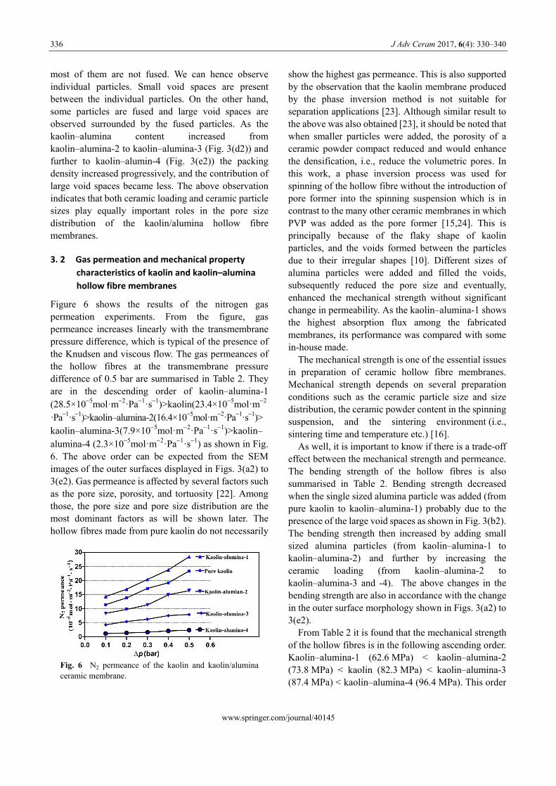
Figure 6 shows the results of the nitrogen gas permeation experiments. From the figure, gas permeance increases linearly with the transmembrane pressure difference, which is typical of the presence of the Knudsen and viscous flow. The gas permeances of the hollow fibres at the transmembrane pressure difference of 0.5 bar are summarised in Table 2. They are in the descending order of kaolin–alumina-1 (28.5×10⁵mol·m2·Pa1·s1)>kaolin(23.4×10⁵mol·m2
·Pa1·s1)>kaolin–alumina-2(16.4×10⁵mol·m2·Pa1·s1)> kaolin–alumina-3(7.9×10⁵mol·m2·Pa1·s1)>kaolin– alumina-4 (2.3×10⁵mol·m2·Pa1·s1) as shown in Fig. 6. The above order can be expected from the SEM images of the outer surfaces displayed in Figs. 3(a2) to 3(e2). Gas permeance is affected by several factors such as the pore size, porosity, and tortuosity [22]. Among those, the pore size and pore size distribution are the most dominant factors as will be shown later. The hollow fibres made from pure kaolin do not necessarily
show the highest gas permeance. This is also supported by the observation that the kaolin membrane produced by the phase inversion method is not suitable for separation applications [23]. Although similar result to the above was also obtained [23], it should be noted that when smaller particles were added, the porosity of a ceramic powder compact reduced and would enhance the densification, i.e., reduce the volumetric pores. In this work, a phase inversion process was used for spinning of the hollow fibre without the introduction of pore former into the spinning suspension which is in contrast to the many other ceramic membranes in which PVP was added as the pore former [15,24]. This is principally because of the flaky shape of kaolin particles, and the voids formed between the particles due to their irregular shapes [10]. Different sizes of alumina particles were added and filled the voids, subsequently reduced the pore size and eventually, enhanced the mechanical strength without significant change in permeability. As the kaolin–alumina-1 shows the highest absorption flux among the fabricated membranes, its performance was compared with some in-house made.
The mechanical strength is one of the essential issues in preparation of ceramic hollow fibre membranes. Mechanical strength depends on several preparation conditions such as the ceramic particle size and size distribution, the ceramic powder content in the spinning suspension, and the sintering environment (i.e., sintering time and temperature etc.) [16].
As well, it is important to know if there is a trade-off effect between the mechanical strength and permeance. The bending strength of the hollow fibres is also summarised in Table 2. Bending strength decreased when the single sized alumina particle was added (from pure kaolin to kaolin–alumina-1) probably due to the presence of the large void spaces as shown in Fig. 3(b2). The bending strength then increased by adding small sized alumina particles (from kaolin–alumina-1 to kaolin–alumina-2) and further by increasing the ceramic loading (from kaolin–alumina-2 to kaolin–alumina-3 and -4). The above changes in the bending strength are also in accordance with the change in the outer surface morphology shown in Figs. 3(a2) to 3(e2).
From Table 2 it is found that the mechanical strength of the hollow fibres is in the following ascending order. Kaolin–alumina-1 (62.6 MPa) < kaolin–alumina-2 (73.8 MPa) < kaolin (82.3 MPa) < kaolin–alumina-3 (87.4 MPa) < kaolin–alumina-4 (96.4 MPa). This order
Fig. 6 N2 permeance of the kaolin and kaolin/alumina ceramic membrane.
J Adv Ceram 2017, 6(4): 330–340
www.springer.com/journal/40145
337
is the same as the descending order of nitrogen permeance except for the interchange of the positions of kaolin–alumina-2 and kaolin. Therefore, it can be concluded that there is a trade-off effect between the mechanical strength and the gas permeability among the studied hollow fibres.
3. 3 Crystal structure of membranes
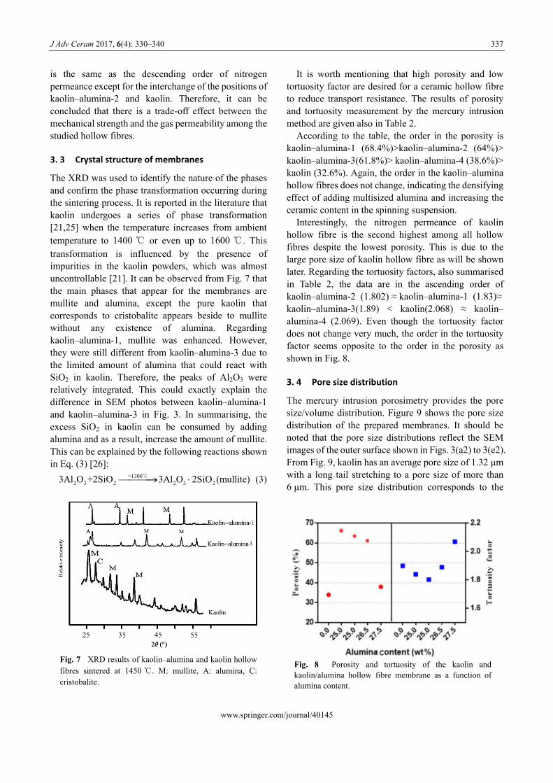
The XRD was used to identify the nature of the phases and confirm the phase transformation occurring during the sintering process. It is reported in the literature that kaolin undergoes a series of phase transformation [21,25] when the temperature increases from ambient temperature to 1400 ℃ or even up to 1600 ℃. This transformation is influenced by the presence of impurities in the kaolin powders, which was almost uncontrollable [21]. It can be observed from Fig. 7 that the main phases that appear for the membranes are mullite and alumina, except the pure kaolin that corresponds to cristobalite appears beside to mullite without any existence of alumina. Regarding kaolin–alumina-1, mullite was enhanced. However, they were still different from kaolin–alumina-3 due to the limited amount of alumina that could react with SiO2 in kaolin. Therefore, the peaks of Al2O3 were relatively integrated. This could exactly explain the difference in SEM photos between kaolin–alumina-1 and kaolin–alumina-3 in Fig. 3. In summarising, the excess SiO2 in kaolin can be consumed by adding alumina and as a result, increase the amount of mullite. This can be explained by the following reactions shown in Eq. (3) [26]:
>13002 3 2 2 3 23Al O +2SiO 3Al O 2SiO (mullite)
C (3)
It is worth mentioning that high porosity and low tortuosity factor are desired for a ceramic hollow fibre to reduce transport resistance. The results of porosity and tortuosity measurement by the mercury intrusion method are given also in Table 2.
According to the table, the order in the porosity is kaolin–alumina-1 (68.4%)>kaolin–alumina-2 (64%)> kaolin–alumina-3(61.8%)> kaolin–alumina-4 (38.6%)> kaolin (32.6%). Again, the order in the kaolin–alumina hollow fibres does not change, indicating the densifying effect of adding multisized alumina and increasing the ceramic content in the spinning suspension.
Interestingly, the nitrogen permeance of kaolin hollow fibre is the second highest among all hollow fibres despite the lowest porosity. This is due to the large pore size of kaolin hollow fibre as will be shown later. Regarding the tortuosity factors, also summarised in Table 2, the data are in the ascending order of kaolin–alumina-2 (1.802) ≈ kaolin–alumina-1 (1.83)≈ kaolin–alumina-3(1.89) < kaolin(2.068) ≈ kaolin– alumina-4 (2.069). Even though the tortuosity factor does not change very much, the order in the tortuosity factor seems opposite to the order in the porosity as shown in Fig. 8.
3. 4 Pore size distribution
The mercury intrusion porosimetry provides the pore size/volume distribution. Figure 9 shows the pore size distribution of the prepared membranes. It should be noted that the pore size distributions reflect the SEM images of the outer surface shown in Figs. 3(a2) to 3(e2). From Fig. 9, kaolin has an average pore size of 1.32 μm with a long tail stretching to a pore size of more than 6 μm. This pore size distribution corresponds to the
Fig. 8 Porosity and tortuosity of the kaolin and kaolin/alumina hollow fibre membrane as a function of alumina content.
Fig. 7 XRD results of kaolin–alumina and kaolin hollow fibres sintered at 1450 ℃. M: mullite, A: alumina, C: cristobalite.

J Adv Ceram 2017, 6(4): 330–340
www.springer.com/journal/40145
338
surface image shown in Fig. 3(a2). The average pore size of kaolin–alumina-1 increased to 1.93 μm also with a long tail to large pore sizes, which corresponds to the image in Fig. 3(b2). Interestingly, a bimodal distribution was obtained for kaolin–alumina-2 with the average pores size of 0.55 and 2.09 μm. The small pores represent the void spaces between the individual particles, while the large pores represent the large void spaces between the fused particles, as observed in the SEM image of Fig. 3(c2). In kaolin–alumina-3, the contribution of the second (larger) pore size distribution decreased as shown in Fig. 3(d2) and finally in kaolin–alumina-4 the second pore size distribution
practically disappeared and only a pore size distribution of the first (smaller) distribution with an average size of 0.25 μm remained, which corresponds to the image shown in Fig. 3(e2).
The average size of the smaller pores is in the descending order of kaolin–alumina-1(1.93 μm)> kaolin(1.32 μm)>kaolin–alumina-2(0.55 μm) > kaolin– alumina-3(0.29 μm)>kaolin–alumina-4(0.25 μm). The permeance decreased exactly in the same order. Therefore, it can be concluded that it is the pore size that governs the nitrogen gas permeance.
3. 5 Contact angle
The wettability of the membrane surface should be low to prevent the liquid penetration into the pores when the liquid is brought into contact with the membrane surface. The contact angles of the studied hollow fibres are listed in Table 2. In Table 2, all the hollow fibres showed very high contact angles of above 138°, except for kaolin–alumina-1 hollow fibre, indicating that most of them are useful for membrane contactor applications in which an aqueous solution is used as the absorbent. The high hydrophobicity is due to the successful surface modification by FAS. The exceptionally low contact angle of kaolin–alumina-1 is likely due to the presence of large pores, which allowed the penetration of water into the pores. The partial wetting of the membrane has probably lowered the average hydrophobicity of the membrane surface.
3. 6 Comparison with previous works
Recently, the development of kaolin–alumina has attracted attention. This is due to the high surface area promoted by the membranes, enabling good performance. Table 3 reports the comparison of kaolin–alumina-3 in previous studies towards membrane gas permeation and hydrophobicity. As shown, the gas permeance value obtained in this work is comparable to other works on the effects of ceramic contents and sintering temperature [15,23,27–31].
Fig. 9 Pore size distribution for membrane fabricated at different kaolin and kaolin/alumina ratio.
Table 3 Comparison of ceramic membrane gas permeation and hydrophobicity in this study with previous works
Membrane Ceramic content (wt%)
Sintering temperature (℃)
Gas permeation (N2 0.5 bar)(105mol·m2·Pa1·s1) Contact angle (°) Reference
Kaolin 45 1400 19 — [27] Al2O3 50 1450 5 — [23] TiO2 23 1300 6 — [28] Si3N4 58 1700 1.04 136 [29]
β-SiAlON 52 1500 4.6 125 [30] YSZ 66 1475 0.013 — [31]
Kaolin–alumina 53 1400 7.9 142 Present study

J Adv Ceram 2017, 6(4): 330–340
www.springer.com/journal/40145
339
Therefore, it is suggested that kaolin–alumina possesses high permeability and high hydrophobicity at low cost due to the ceramic content used and the price of the material.
4 Conclusions
Affordable hydrophobic ceramic hollow fibres have been successfully prepared using the phase inversion, sintering technique, and surface grafting with fluoroalkylsilane (FAS). The effects of particle loading and particle sizes on the membrane physical properties were discussed and several conclusions could be drawn as follows:
The ceramic loading and particle shape/size have an equally significant effect on the structure of hollow fibre membranes. Finger-like structure can be obtained when the suspension contains multiparticle instead of mono-particle since the graded particles promote the exchange between the solvent and nonsolvent. In addition, the small particles move faster than the large ones to the surface during phase inversion process and as a result, the nanoparticles offer short path through the membrane section which makes fast precipitation.
The superhydrophobic membrane can be obtained by using alumina and/or kaolin as membrane materials since kaolin surface possesses a large number of O–H groups which readily react with FAS during the grafting process.
The prepared kaolin–alumina hollow fibre membranes offer high gas permeance ((2.3–28.5)× 105mol·m2·Pa1·s1) with respect to the mechanical strength of the membranes. On top of that, this study provides an insight into the development of ceramic with controllable permeability and high strength for the membrane.
The flaky shape and low specific gravity of kaolin are obstacles for achieving maximum benefit from this material, i.e., low cost and low sintering temperature. Thus, the membrane prepared from pure kaolin by using phase inversion process may need to be improved in future based on the results and analysis from this study, to ensure it can be used for critical applications with targeting in reducing the membrane cost of material.
Acknowledgements
The authors gratefully acknowledge the financial support from Universiti Teknologi Malaysia under Research
University Grant Tier 1 (Project No. Q.J130000.2546.12H25) and Flagship UTMShine (Project No. Q.J130000.2446.03G29), and Nippon Sheet Glass Foundation for Materials Science and Engineering under Overseas Research Grant Scheme (Project No. Q.J130000.2446.03G29). The authors also would like to thank Research Management Centre, Universiti Teknologi Malaysia for the technical support.
References
[1] Sarkar S, Bandyopadhyay S, Larbot A, et al. New clay–alumina porous capillary supports for filtration application. J Membrane Sci 2012, 392–393: 130–136.
[2] Kingsbury BFK, Li K. A morphological study of ceramic hollow fibre membranes. J Membrane Sci 2009, 328: 134–140.
[3] Drioli E, Criscuoli A, Curcio E. Membrane Contactors: Fundamentals, Applications and Potentialities, Volume 11. Elsevier Science, 2005.
[4] Aroon MA, Ismail AF, Matsuurabc T, et al. Performance studies of mixed matrix membranes for gas separation: A review. Sep Purif Technol 2010, 75: 229–242.
[5] Xu A, Yang A, Young S, et al. Effect of internal coagulant on effectiveness of polyvinylidene fluoride membrane for carbon dioxide separation and absorption. J Membrane Sci 2008, 311: 153–158.
[6] Nishikawa N, Ishibashi M, Ohta H, et al. CO2 removal by hollow-fiber gas–liquid contactor. Energ Convers Manage 1995, 36: 415–418.
[7] Dindore V, Brilman DWF, Feronc PHM, et al. CO2 absorption at elevated pressures using a hollow fiber membrane contactor. J Membrane Sci 2004, 235: 99–109.
[8] Yu X, An L, Yang J, et al. CO2 capture using a superhydrophobic ceramic membrane contactor. J Membrane Sci 2015, 496: 1–12.
[9] Faiz R, Fallanza M, Ortiz I, et al. Separation of olefin/paraffin gas mixtures using ceramic hollow fiber membrane contactors. Ind Eng Chem Res 2013, 52: 7918–7929.
[10] Abdulhameed MA, Othman MHD, Ismail AF, et al. Carbon dioxide capture using a superhydrophobic ceramic hollow fibre membrane for gas–liquid contacting process. J Clean Prod 2017, 140: 1731–1738.
[11] Koonaphapdeelert S, Wu Z, Li K. Carbon dioxide stripping in ceramic hollow fibre membrane contactors. Chem Eng Sci 2009, 64: 1–8.
[12] Koonaphapdeelert S, Li K. Preparation and characterization of hydrophobic ceramic hollow fibre membrane. J Membrane Sci 2007, 291: 70–76.
[13] Bouzerara F, Harabi A, Condom S. Porous ceramic membranes prepared from kaolin. Desalin Water Treat 2009, 12: 415–419.
[14] Boudaira B, Harabia A, Bouzerara F, et al. Preparation and characterization of microfi ltration membranes and their supports using kaolin (DD2) and CaCO3. Desalin Water

J Adv Ceram 2017, 6(4): 330–340
www.springer.com/journal/40145
340
Treat 2009, 9: 142–148. [15] Han L-F, Xu Z-L, Cao Y, et al. Preparation,
characterization and permeation property of Al2O3, Al2O3–SiO2 and Al2O3–kaolin hollow fiber membranes. J Membrane Sci 2011, 372: 154–164.
[16] Li K. Ceramic Membranes for Separation and Reaction. John Wiley & Sons, Ltd., 2007.
[17] Schneider H, Schreuer J, Hildmann B. Structure and properties of mullite—A review. J Eur Ceram Soc 2008, 28: 329–344.
[18] Wei CC, Li K. Preparation and characterization of a robust and hydrophobic ceramic membrane via an improved surface grafting technique. Ind Eng Chem Res 2009, 48: 3446–3452.
[19] Shao J, Zhan Z, Li J, et al. Zeolite NaA membranes supported on alumina hollow fibers: Effect of support resistances on pervaporation performance. J Membrane Sci 2014, 451: 10–17.
[20] Li K. Ceramic hollow fiber membranes and their applications. In: Comprehensive Membrane Science and Engineering. Drioli E, Giorno L, Eds. Oxford: Elsevier, 2010: 253–273.
[21] Chakraborty AK. Phase Transformation of Kaolinite Clay. India: Springer, 2013.
[22] Falamaki C, Afarani MS, Aghaie A. Initial sintering stage pore growth mechanism applied to the manufacture of ceramic membrane supports. J Eur Ceram Soc 2004, 24: 2285–2292.
[23] Liu S, Li K, Hughes R. Preparation of porous aluminium oxide (Al2O3) hollow fibre membranes by a combined phase-inversion and sintering method. Ceram Int 2003, 29: 875–881.
[24] Liu S, Li K, Hughes R. Preparation of porous aluminium oxide (Al2O3) hollow fibre membranes by a combined phase-inversion and sintering method. Ceram Int 2003, 29: 875–881.
[25] Chen CY, Lan GS, Tuan WH. Preparation of mullite by the reaction sintering of kaolinite and alumina. J Eur Ceram Soc 2000, 20: 2519–2525.
[26] Chen G, Qi H, Xing W, et al. Direct preparation of macroporous mullite supports for membranes by in situ reaction sintering. J Membrane Sci 2008, 318: 38–44.
[27] Abdulhameed MA, Othman MHD, Ismail AF, et al. Preparation and characterisation of inexpensive porous kaolin hollow fibre as ceramic membrane supports for gas separation application. J Aust Ceram Soc 2017, 53: 645–655.
[28] Rahman MA, Ghazali MA, Aizi WMSWA, et al. Preparation of titanium dioxide hollow fiber membrane using phase inversion and sintering technique for gas separation and water purification. Sains Malaysiana 2015, 44: 1195–1201.
[29] Zhang J-W, Fang H, Wang J-W, et al. Preparation and characterization of silicon nitride hollow fiber membranes for seawater desalination. J Membrane Sci 2014, 450: 197–206.
[30] Wang J-W, Li L, Zhang J-W, et al. β-Sialon ceramic hollow fiber membranes with high strength and low thermal conductivity for membrane distillation. J Eur Ceram Soc 2016, 36: 59–65.
[31] Liu L, Tan X, Liu S. Yttria stabilized zirconia hollow fiber membranes. J Am Ceram Soc 2006, 89: 1156–1159.
Open Access The articles published in this journal are distributed under the terms of the Creative Commons Attribution 4.0 International License (http://creativecommons. org/licenses/by/4.0/), which permits unrestricted use, distribution, and reproduction in any medium, provided you give appropriate credit to the original author(s) and the source, provide a link to the Creative Commons license, and indicate if changes were made.