fa100 installation manual h5 10-17-05
TRANSCRIPT
PRINTED IN JAPAN
UAIS TRANSPONDER
FA-100

The paper used in this manual
is elemental chlorine free.
FURUNO Authorized Distributor/DealerFURUNO Authorized Distributor/Dealer
9-52 Ashihara-cho,9-52 Ashihara-cho,Nishinomiya, 662-8580, JAPANNishinomiya, 662-8580, JAPAN
Telephone :Telephone : 0798-65-21110798-65-2111FaxFax 0798-65-42000798-65-4200::
FIRST EDITION :FIRST EDITION : SEP.SEP. 20022002Printed in JapanPrinted in JapanAll rights reserved.All rights reserved.H5H5 :: OCT.OCT. 17, 200517, 2005
Pub. No.Pub. No. IME-44170-H5IME-44170-H5
*00080932513**00080932513*(( AKMUAKMU )) FA-100FA-100*00080932513**00080932513*
* 0 0 0 8 0 9 3 2 5 1 3 ** 0 0 0 8 0 9 3 2 5 1 3 *

i
SAFETY INSTRUCTIONS
WARNING
Turn off the power at the switchboardbefore beginning the installation.
Fire or electrical shock can result if thepower is left on.
Do not install the equipment where itmay get wet from rain or water splash.
Water in the equipment can result in fire,electrical shock or damage the equipment.
Be sure that the power supply iscompatible with the voltage rating ofthe equipment.
Connection of an incorrect power supplycan cause fire or damage the equipment. The voltage rating of the equipment appearson the label above the power connector.
ELECTRICAL SHOCK HAZARDDo not open the equipmentunless totally familiar withelectrical circuits andservice manual.
Only qualified personnelshould work inside theequipment.
CAUTIONObserve the following compass safedistances to prevent interference to amagnetic compass:
Standardcompass
Steeringcompass
FA-100 1.0 m 0.6 m
CB-100 0.6 m 0.4 m
GVA-100 0.3 m 0.3 m
DB-1 0.3 m 0.3 m
PR-240-CE 0.9m 0.6 m
Attach securely protectionearth to the ship's body.
The protection earth is required to the power supply to prevent electrical shock

ii
TABLE OF CONTENTS
SYSTEM CONFIGURATION................................................................................ iii EQUIPMENT LISTS ............................................................................................. iv
1. MOUNTING ....................................................................................................... 1 1.1 Antenna Unit....................................................................................................................1
1.1.1 GPS antenna unit ...............................................................................................1 1.1.2 VHF antenna ......................................................................................................3 1.1.3 GPS/VHF combined antenna ..............................................................................5
1.2 Transponder Unit .............................................................................................................8 1.3 Junction Box..................................................................................................................10 1.4 Power Supply (option) ...................................................................................................11 1.5 Pilot Plug (option) ..........................................................................................................11
2. WIRING ........................................................................................................... 12
3. INPUT/OUTPUT SIGNAL ............................................................................... 15 3.1 Inputs from Sensors.......................................................................................................15 3.2 Input/Output of AIS Signal .............................................................................................16 3.3 Input of Gyrocompass Signal.........................................................................................17 3.4 Alarm Signal Output.......................................................................................................17 3.5 LAN Input/Output...........................................................................................................18 3.6 Pilot Plug .......................................................................................................................18 3.7 Jumper Setting in the Junction Box................................................................................19 3.8 Input/Output Sentences.................................................................................................20 3.9 Changing Ship’s Mains Specifications............................................................................21
4. SETTING AND ADJUSTMENT....................................................................... 22 4.1 Setting MMSI, IMO No., Name and Call Sign ................................................................22 4.2 Setting GPS Antenna Position and Ship’s Type .............................................................24 4.3 System Settings.............................................................................................................26
PACKING LIST OUTLINE DRAWINGS INTERCONNECTION DIAGRAM

iii
SYSTEM CONFIGURATION
: Standard
: Option
GPS/VHFcombined antennaGVA-100
GPS antennaGPA-017SGSC-001
Distributor unitDB-1
VHF whip antenna
Transponder unitFA-100
Junction box CB-100
Other external equipments
Power supplyPR-240-CE
100-115/200-230 VAC1f, 50/60Hz 12-24 VDC
Ship’s mains: Local supply
Either
24 VDC
GPS Navigator *
*: External GPS Navigation is required.
Gyrocompass
AD-100
Category of the units GPA-017S Exposed to the weather GSC-001 Exposed to the weather GVA-100 Exposed to the weather FA-100 Protected from the weather CB-100 Protected from the weather DB-1 Protected from the weather PR-240-CE Protected from the weather
iv
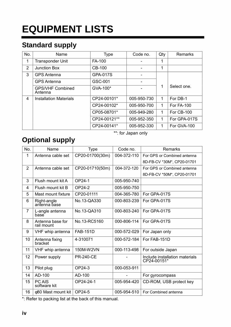
EQUIPMENT LISTS Standard supply No. Name Type Code no. Qty Remarks 1 Transponder Unit FA-100 - 1 2 Junction Box CB-100 - 1
GPS Antenna GPA-017S - GPS Antenna GSC-001 -
3
GPS/VHF Combined Antenna
GVA-100* -
1
Select one.
CP24-00101* 005-950-730 1 For DB-1 CP24-00102* 005-950-700 1 For FA-100 CP05-08701* 005-949-280 1 For CB-100 CP24-00121** 005-952-350 1 For GPA-017S
4 Installation Materials
CP24-00141* 005-952-330 1 For GVA-100 **: for Japan only
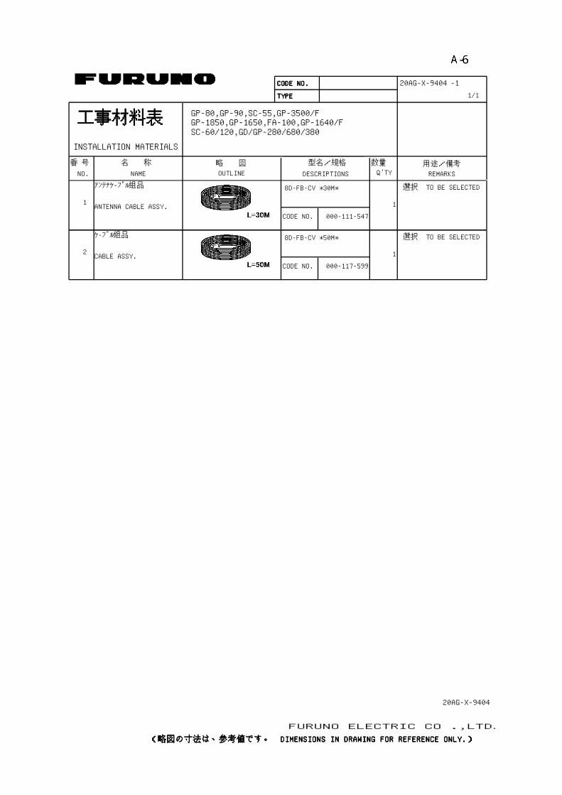
Optional supply No. Name Type Code no. Remarks 1 Antenna cable set CP20-01700(30m) 004-372-110 For GPS or Combined antenna
8D-FB-CV *30M*, CP20-01701 2 Antenna cable set CP20-01710(50m) 004-372-120 For GPS or Combined antenna
8D-FB-CV *50M*, CP20-01701 3 Flush mount kit A OP24-1 005-950-740 4 Flush mount kit B OP24-2 005-950-750 5 Mast mount fixture CP20-01111 004-365-780 For GPA-017S 6 Right-angle
antenna base No.13-QA330 000-803-239 For GPA-017S
7 L-angle antenna base
No.13-QA310 000-803-240 For GPA-017S
8 Antenna base for rail mount
No.13-RC5160 000-806-114 For GPA-017S
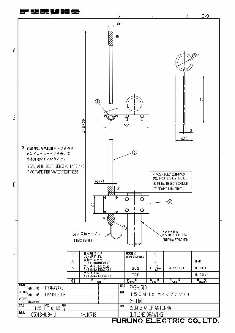
9 VHF whip antenna FAB-151D 000-572-029 For Japan only
10 Antenna fixing bracket
4-310071 000-572-184 For FAB-151D
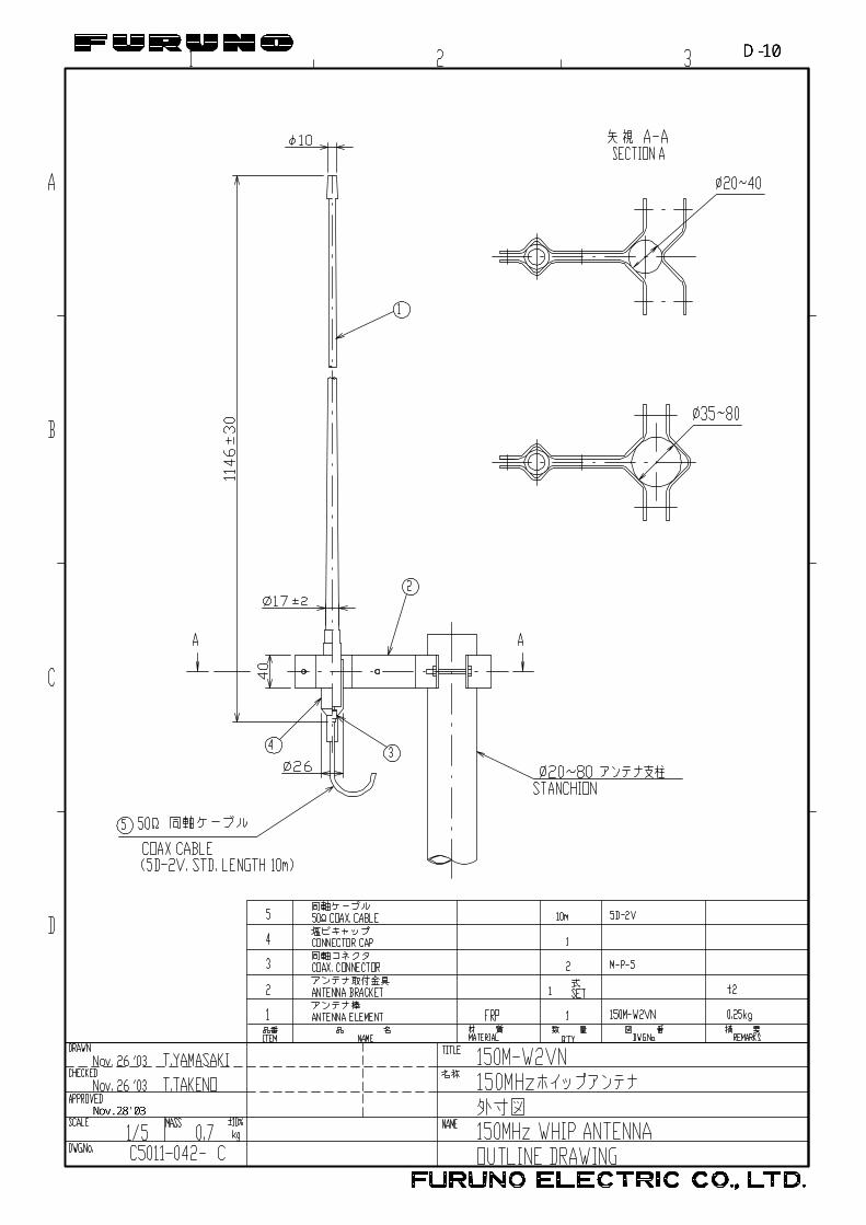
11 VHF whip antenna 150M-W2VN 000-113-498 For outside Japan 12 Power supply PR-240-CE - Include installation materials
CP24-00151* 13 Pilot plug OP24-3 000-053-911
14 AD-100 AD-100 - For gyrocompass 15 PC AIS
software kit OP24-24-1 005-954-420 CD-ROM, USB protect key
16 φ80 Mast mount kit OP24-5 005-954-510 For Combined antenna *: Refer to packing list at the back of this manual.

1
1. MOUNTING
1.1 Antenna Unit 1.1.1 GPS antenna unit Install the GPS antenna unit referring to the drawing at the back of this manual D-1. When selecting a mounting location for the antenna, keep in mind the following points. • Select a location out of the radar beam. The radar beam will obstruct or prevent
reception of the GPS satellite signal. • There should be no interfering object within the line-of-sight to the satellites. Objects
within line-of-sight to a satellite, for example, a mast, may block reception or prolong acquisition time.
• Mount the antenna unit as high as possible to keep it free of interfering objects and water spray, which can interrupt reception of GPS satellite signal if the water freezes.
Extending antenna cable
Three types of antenna cable extensions are optionally available. a) Antenna cable set CP20-01700
Antenna Unit
1 m
Antenna Cable
30 m 1 m
Fabricate locally. (See next page.)
FA-100
: ConnectorConversionCable Assy.NJ-TP-3DXV-1
0.6 m
◆ Waterproofing connector Wrap connector with vulcanizing tape and then vinyl tape. Bind the tape end with a cable-tie.
Waterproofing connector b) Antenna cable set CP20-01710 (8D-FB-CV, 50m)
Connect the cable the same as a) above. c) Cable type RG-10U/Y (shipyard supply)
Note: The length of this cable should be less than 20 m to prevent signal loss. The coax. coupling cable assy.(type: NJ-TP+3DXV-1, code no. 000-123-809), coaxial connector(N-P-8DFB; supplied), vulcanizing tape and vinyl tape are required. Fabricate both ends of the cable as shown in the figure on the next page.

2
How to attach the connector N-P-8DFB for cable 8D-FB-CV Outer Sheath
ArmorDimensions in millimeters.
Inner Sheath Shield
Remove outer sheath and armor by the dimensions shown left.Expose inner sheath and shield by the dimensions shown left.
Cut off insulator and core by 10mm.
Twist shield end.
Ship on clamp nut, gasket and clamp as shown left.
Fold back shield over clamp and trim.
Cut aluminum foil at four places, 90° from one another.
Fold back aluminum foil onto shield and trim.
Expose the insulator by 1mm.
Expose the core by 5mm.
Slip the pin onto the conductor. Solder them together through the hole on the pin.
Insert the pin into the shell. Screw the clamp nut into the shell.(Tighten by turning the clamp nut. Do not tighten by turning the shell.)
Cover with heat-shrink tubing and heat.
30 10
ClampNut
Gasket(reddishbrown)
Clamp
Aluminum Foil
Trim shield here.
Trim aluminumtape foil here.
Insulator
1
5
Clamp NutPin
Shell
Solder throughthe hole.
50 30
How to attach connector N-P-8DFB

3
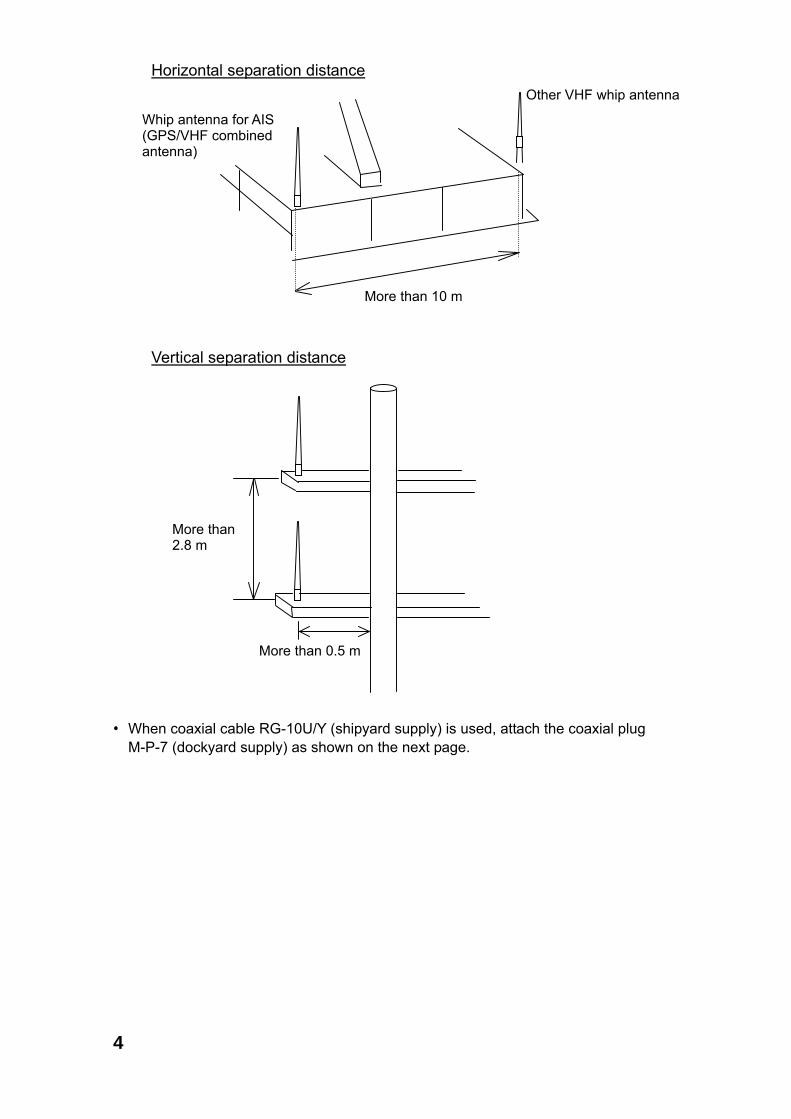
1.1.2 VHF antenna Location Location of the mandatory AIS VHF-antenna should be carefully considered. Digital communication is more sensitive than analog/voice communication to interference created by reflections in obstructions like masts and booms. It may be necessary to relocate the VHF radiotelephone antenna to minimize interference effects. To minimise interference effects, the following guidelines apply: • The AIS VHF antenna should be placed in an elevated position that is as free as
possible with a minimum of 0.5 meters in the horizontal direction from constructions made of conductive materials. The antenna should not be installed close to any large vertical obstruction. The objective for the AIS VHF antenna is to see the horizon freely through 360 degrees.
• The AIS VHF antenna should be installed safely away from interfering high-power energy sources like radar and other transmitting radio antennas, preferably at least 3 meters away from and out of the transmitting beam.
• There should not be more than one antenna on the same plane. The AIS VHF antenna should be mounted directly above or below the ship’s primary VHF radiotelephone antenna, with no horizontal separation and with a minimum of 2.8 meters vertical separation. If it is located on the same plane as other antennas, the distance apart should be at least 10 meters.
Cabling • The cable should be kept as short as possible to minimize signal attenuation.
Coaxial cables equal to or better than RG10U/Y are recommended. • All outdoor installed connectors on coaxial cables should be fitted with preventive
isolation such as vulcanizing tape to protect against water penetration into the antenna cable.
• Coaxial cables should be installed in separate signal cable channels/tubes and at
least 10 cm away from power supply cables. Crossing of cables should be done at right angles (90°). The minimum bend radius of the coaxial cable should be 5 times the cable's outer diameter.
• Install the VHF whip antenna referring to the outline drawing at the back of this
manual. Separate this antenna from other VHF radiotelephone antennas as shown on the next page to prevent interference to the FA-100.
4
• When coaxial cable RG-10U/Y (shipyard supply) is used, attach the coaxial plug
M-P-7 (dockyard supply) as shown on the next page.
Horizontal separation distance
More than 10 m
More than 0.5 m
More than 2.8 m
Vertical separation distance
Other VHF whip antenna
Whip antenna for AIS (GPS/VHF combined antenna)
5
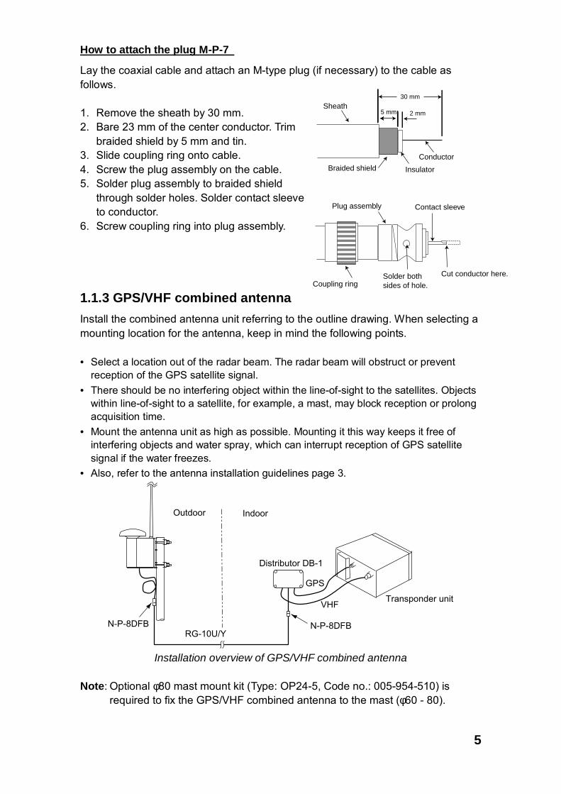
How to attach the plug M-P-7
Lay the coaxial cable and attach an M-type plug (if necessary) to the cable as follows. 1. Remove the sheath by 30 mm. 2. Bare 23 mm of the center conductor. Trim
braided shield by 5 mm and tin. 3. Slide coupling ring onto cable. 4. Screw the plug assembly on the cable. 5. Solder plug assembly to braided shield
through solder holes. Solder contact sleeve to conductor.
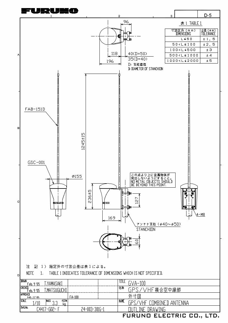
6. Screw coupling ring into plug assembly. 1.1.3 GPS/VHF combined antenna Install the combined antenna unit referring to the outline drawing. When selecting a mounting location for the antenna, keep in mind the following points. • Select a location out of the radar beam. The radar beam will obstruct or prevent
reception of the GPS satellite signal. • There should be no interfering object within the line-of-sight to the satellites. Objects
within line-of-sight to a satellite, for example, a mast, may block reception or prolong acquisition time.
• Mount the antenna unit as high as possible. Mounting it this way keeps it free of interfering objects and water spray, which can interrupt reception of GPS satellite signal if the water freezes.
• Also, refer to the antenna installation guidelines page 3.
Outdoor Indoor
N-P-8DFBN-P-8DFB
Distributor DB-1
GPS
Transponder unitVHF
RG-10U/Y
Installation overview of GPS/VHF combined antenna
Note: Optional φ80 mast mount kit (Type: OP24-5, Code no.: 005-954-510) is required to fix the GPS/VHF combined antenna to the mast (φ60 - 80).
Sheath30 mm
5 mm 2 mm
Conductor
InsulatorBraided shield
Plug assembly Contact sleeve
Cut conductor here.Solder both sides of hole.Coupling ring
6
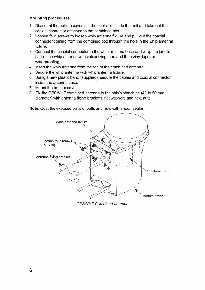
Mounting procedures
1. Dismount the bottom cover, cut the cable-tie inside the unit and take out the coaxial connector attached to the combined box.
2. Loosen four screws to loosen whip antenna fixture and pull out the coaxial connector coming from the combined box through the hole in the whip antenna fixture.
3. Connect the coaxial connector to the whip antenna base and wrap the junction part of the whip antenna with vulcanizing tape and then vinyl tape for waterproofing.
4. Insert the whip antenna from the top of the combined antenna. 5. Secure the whip antenna with whip antenna fixture. 6. Using a new plastic band (supplied), secure the cables and coaxial connector
inside the antenna case. 7. Mount the bottom cover. 8. Fix the GPS/VHF combined antenna to the ship’s stanchion (40 to 50 mm
diameter) with antenna fixing brackets, flat washers and hex. nuts. Note: Coat the exposed parts of bolts and nuts with silicon sealant.
Whip antenna fixture
Antenna fixing bracket
Bottom cover
Combined box
Loosen four screws.(M5x16)
GPS/VHF Combined antenna
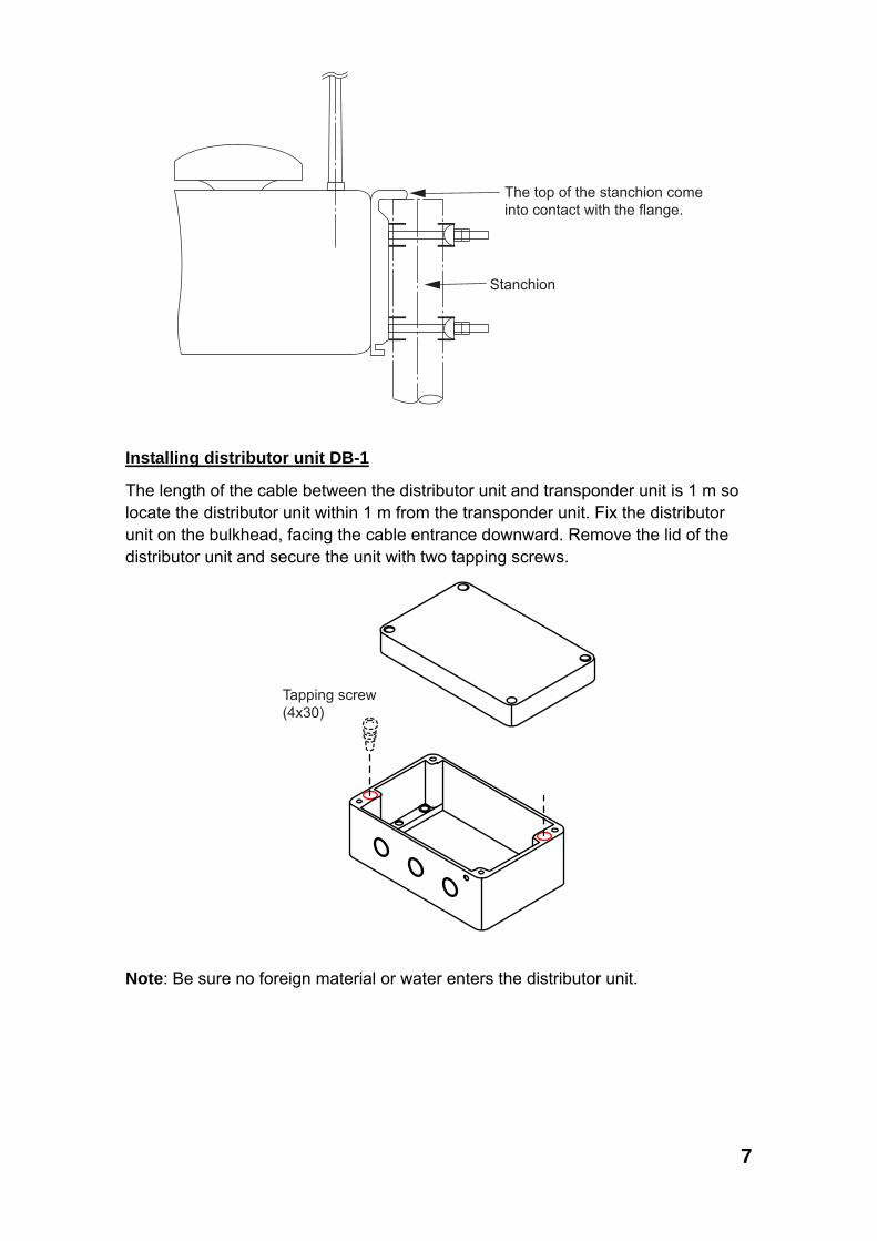
7
Stanchion
The top of the stanchion comeinto contact with the flange.
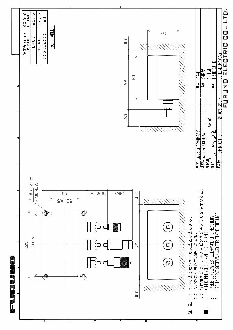
Installing distributor unit DB-1
The length of the cable between the distributor unit and transponder unit is 1 m so locate the distributor unit within 1 m from the transponder unit. Fix the distributor unit on the bulkhead, facing the cable entrance downward. Remove the lid of the distributor unit and secure the unit with two tapping screws.
Tapping screw(4x30)
Note: Be sure no foreign material or water enters the distributor unit.
8
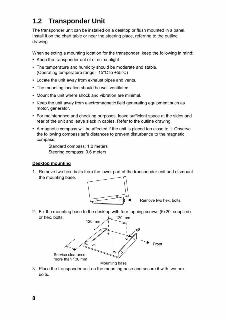
1.2 Transponder Unit The transponder unit can be installed on a desktop or flush mounted in a panel. Install it on the chart table or near the steering place, referring to the outline drawing. When selecting a mounting location for the transponder, keep the following in mind: • Keep the transponder out of direct sunlight.
• The temperature and humidity should be moderate and stable. (Operating temperature range: -15°C to +55°C)
• Locate the unit away from exhaust pipes and vents.
• The mounting location should be well ventilated.
• Mount the unit where shock and vibration are minimal.
• Keep the unit away from electromagnetic field generating equipment such as motor, generator.
• For maintenance and checking purposes, leave sufficient space at the sides and rear of the unit and leave slack in cables. Refer to the outline drawing.
• A magnetic compass will be affected if the unit is placed too close to it. Observe the following compass safe distances to prevent disturbance to the magnetic compass:
Standard compass: 1.0 meters Steering compass: 0.6 meters
Desktop mounting
1. Remove two hex. bolts from the lower part of the transponder unit and dismount the mounting base.
2. Fix the mounting base to the desktop with four tapping screws (6x20: supplied)
or hex. bolts. 3. Place the transponder unit on the mounting base and secure it with two hex.
bolts.
Remove two hex. bolts.
Service clearance more than 130 mm
Mounting base
Front
120 mm 120 mm
φ8

9
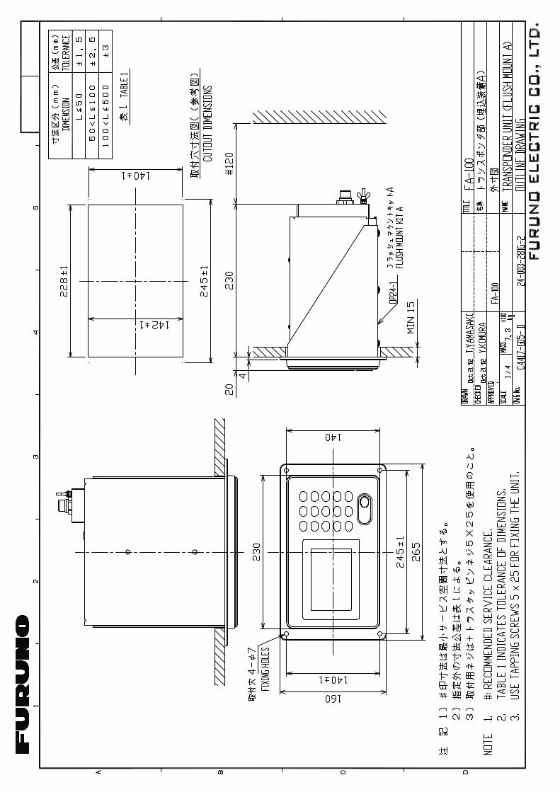
Flush mounting
Optional flush mount kit A or B is required for flush mounting. For mounting dimensions, refer to the outline drawing at the back of this manual. Flush mount kit A: Type OP24-1 Code no. 005-950-740
Name Type Code no. Qty
1 Cosmetic panel 24-003-2811 100-299-540 1
2 +Tapping screw 5x25 000-802-082 4 1. Cut out a hole in the mounting location, referring to the outline drawing. 2. Remove two hex bolts to dismount the mounting base. 3. Remove six hex bolts from the bottom of the transponder unit to dismount the
mounting pedestal. 4. Set the transponder unit to the cosmetic panel and fix them with six hex bolts. 5. Set the assembly (transponder unit and cosmetic panel) to the hole and fix it
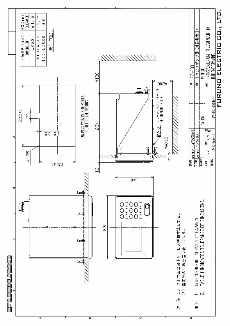
with four tapping screws (5x25). Flush mount kit B: Type OP24-2 Code no. 005-950-750
Name Type Code no. Qty
1 Mounting bracket 24-003-2821 100-299-550 1
2 Hex bolt M5x25 000-862-125 6
3 Hex nut M5 000-863-108 6
4 Flat washer M5 000-864-128 6
5 Spring washer M5 000-864-258 6 1. Cut out a hole in the mounting location, referring to the outline drawing. 2. Dismount the mounting base and mounting pedestal from the transponder unit. 3. Set the transponder unit to the hole. Using six hex bolts, attach the mounting
bracket at the bottom of the transponder unit from the rear of the flush mounting panel.
4. Fix with six sets of hex bolt, nut, flat washers and spring washers from the rear of the flush mounting panel.
10
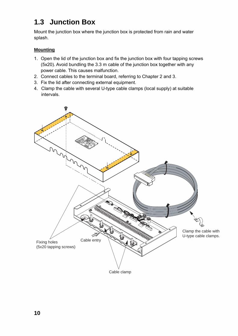
1.3 Junction Box Mount the junction box where the junction box is protected from rain and water splash. Mounting
1. Open the lid of the junction box and fix the junction box with four tapping screws (5x20). Avoid bundling the 3.3 m cable of the junction box together with any power cable. This causes malfunction.
2. Connect cables to the terminal board, referring to Chapter 2 and 3. 3. Fix the lid after connecting external equipment. 4. Clamp the cable with several U-type cable clamps (local supply) at suitable
intervals.
Fixing holes(5x20 tapping screws)
Cable entry
Cable clamp
Clamp the cable with U-type cable clamps.
11
1.4 Power Supply (option) The length of the power cable between the power supply and the transponder unit is 3.5 m. Keep this length in mind when selecting a mounting location. A longer cable should not be used – voltage drop will result, affecting performance. When selecting a mounting location for the unit, keep the following in mind: • Keep the unit out away from areas subject to water splash. • Locate the unit away from exhaust pipes and vents. • The mounting location should be well ventilated. • Mount the unit where shock and vibration are minimal. • A magnetic compass will be affected if the unit is placed too close to it. Observe
the following compass safe distances to prevent disturbance to the magnetic compass:
Steering compass: 0.6 m Standard compass: 0.9 m
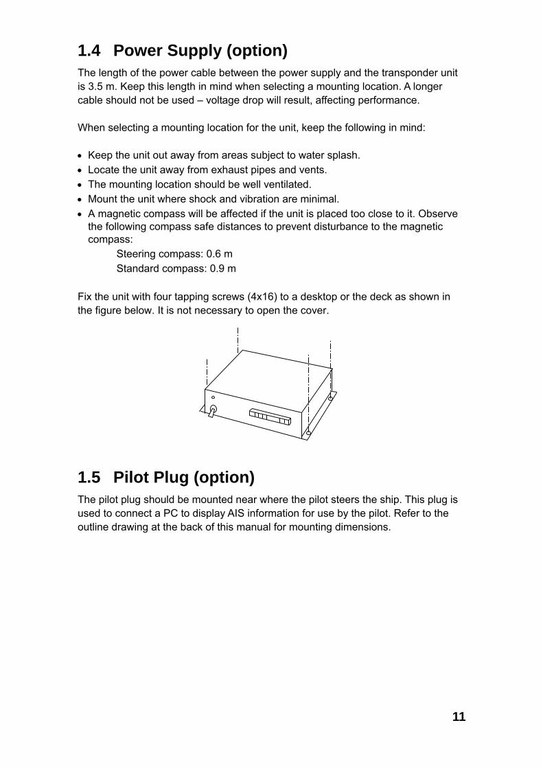
Fix the unit with four tapping screws (4x16) to a desktop or the deck as shown in the figure below. It is not necessary to open the cover.
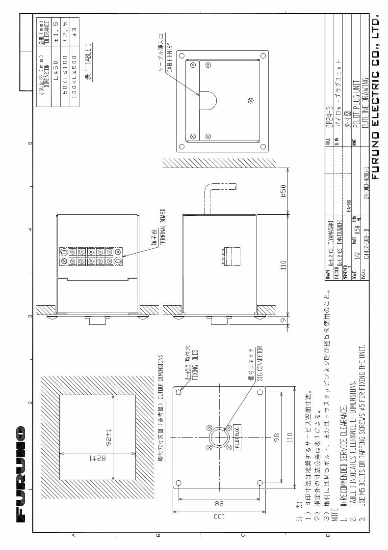
1.5 Pilot Plug (option) The pilot plug should be mounted near where the pilot steers the ship. This plug is used to connect a PC to display AIS information for use by the pilot. Refer to the outline drawing at the back of this manual for mounting dimensions.
12
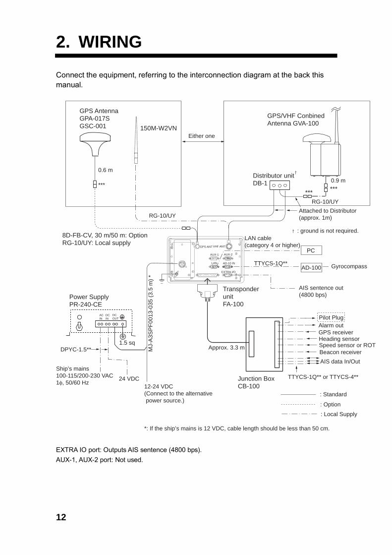
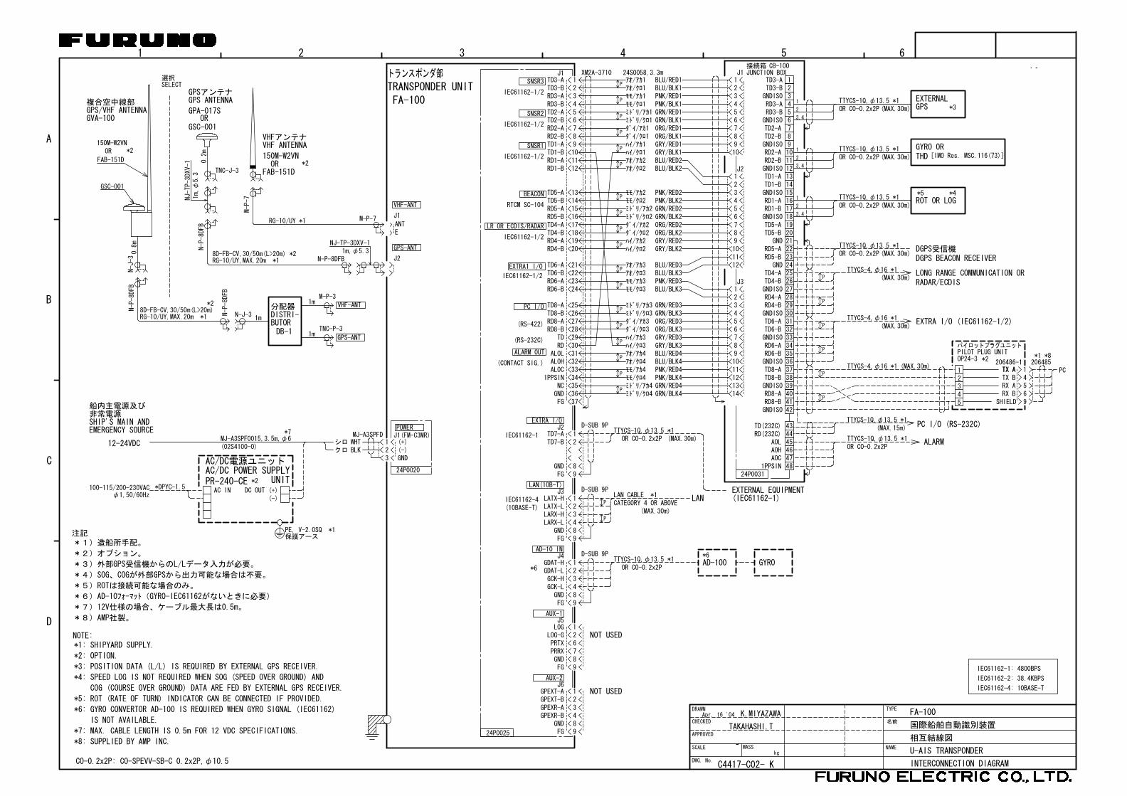
2. WIRING Connect the equipment, referring to the interconnection diagram at the back this manual.
AD-10 IN
EXTRA I/O
GPS AntennaGPA-017SGSC-001
PC
AD-100
150M-W2VNEither one
RG-10/UY
RG-10/UYAttached to Distributor(approx. 1m)
Gyrocompass
LAN cable (category 4 or higher)
TTYCS-1Q**
AIS sentence out(4800 bps)
Distributor unitDB-1
Alarm outGPS receiverHeading sensorSpeed sensor or ROTBeacon receiverAIS data In/Out
Junction BoxCB-100
ACIN
DCIN
DCOUT
12-24 VDC(Connect to the alternative power source.)
*: If the ship’s mains is 12 VDC, cable length should be less than 50 cm.
Ship’s mains100-115/200-230 VAC�1φ, 50/60 Hz
Power SupplyPR-240-CE
MJ-
A3S
PF0
013-
035
(3.5
m) *
TransponderunitFA-100
GPS/VHF ConbinedAntenna GVA-100
8D-FB-CV, 30 m/50 m: OptionRG-10/UY: Local supply
: Standard
: Option
: Local Supply
DPYC-1.5**
LAN
0.6 m
*** ******
0.9 m
GPS ANT VHF ANT
Approx. 3.3 m
TTYCS-1Q** or TTYCS-4**24 VDC
: ground is not required.
1.5 sq
AUX-2AUX-1
Pilot Plug
EXTRA IO port: Outputs AIS sentence (4800 bps). AUX-1, AUX-2 port: Not used.
13
ConductorS = 1.5 mmφ = 1.56 mm
2
DPYC-1.5
Armor
Sheath
φ = 11.7 mm
***: Waterproofing connectors
**: DPYC-1.5, TTYCS-1Q and TTYCS-4 are Japan Industry Standard cable. Use them or the equivalents.
ConductorS = 0.75 mmφ = 1.11 mm
2
TTYCS-1Q (Four core twisted)
Armor
Shield
Sheath
φ = 11.3 mm
ConductorS = 0.75 mmφ = 1.11 mm
2
TTYCS-4 (Four twisted pairs)
Armor
Shield
Sheath
φ = 18.5 mm Sheath
Wrap connector with vulcanizing tape and then vinyl tape. Bind the tape end with a cable-tie.
Waterproofing connector
14
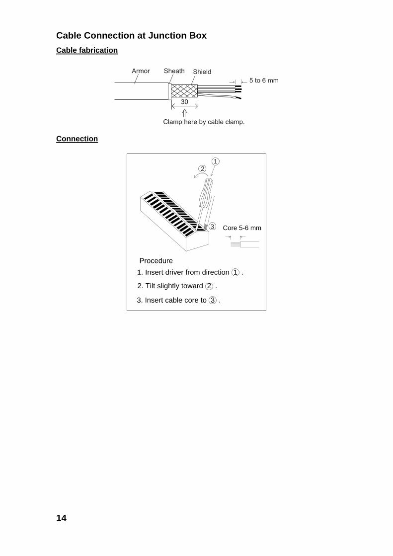
Cable Connection at Junction Box Cable fabrication
Armor Sheath Shield
Clamp here by cable clamp.
5 to 6 mm
30
Connection
Procedure
1. Insert driver from direction 1 .
2. Tilt slightly toward 2 .
3. Insert cable core to 3 .
Core 5-6 mm
12
3
15
3. INPUT/OUTPUT SIGNAL
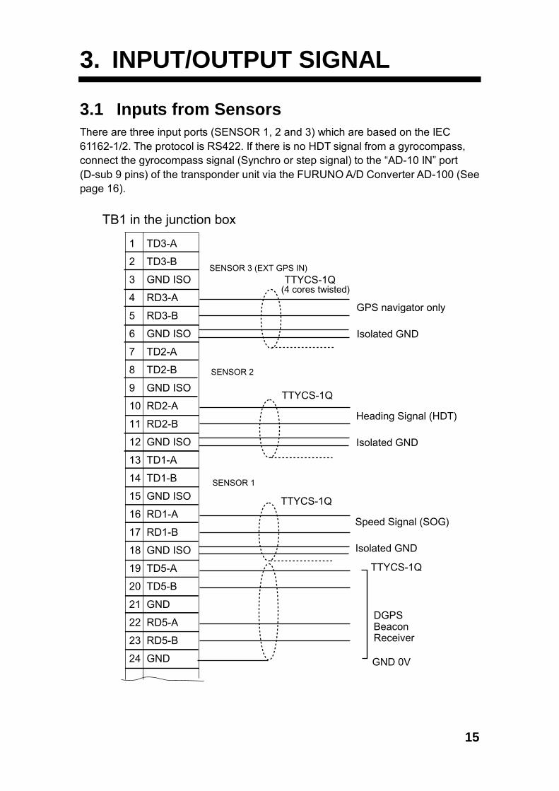
3.1 Inputs from Sensors There are three input ports (SENSOR 1, 2 and 3) which are based on the IEC 61162-1/2. The protocol is RS422. If there is no HDT signal from a gyrocompass, connect the gyrocompass signal (Synchro or step signal) to the “AD-10 IN” port (D-sub 9 pins) of the transponder unit via the FURUNO A/D Converter AD-100 (See page 16).
1 TD3-A
2 TD3-B
3 GND ISO
4 RD3-A
5 RD3-B
6 GND ISO
7 TD2-A
8 TD2-B
9 GND ISO
10 RD2-A
11 RD2-B
12 GND ISO
13 TD1-A
14 TD1-B
15 GND ISO
16 RD1-A
17 RD1-B
18 GND ISO
19 TD5-A
20 TD5-B
21 GND
22 RD5-A
23 RD5-B
24 GND
TB1 in the junction box
GPS navigator only
TTYCS-1Q
Isolated GND
Heading Signal (HDT)
TTYCS-1Q
Isolated GND
Speed Signal (SOG)
TTYCS-1Q
Isolated GND
TTYCS-1Q
GND 0V
DGPS BeaconReceiver
SENSOR 3 (EXT GPS IN)
SENSOR 2
SENSOR 1
(4 cores twisted)
16
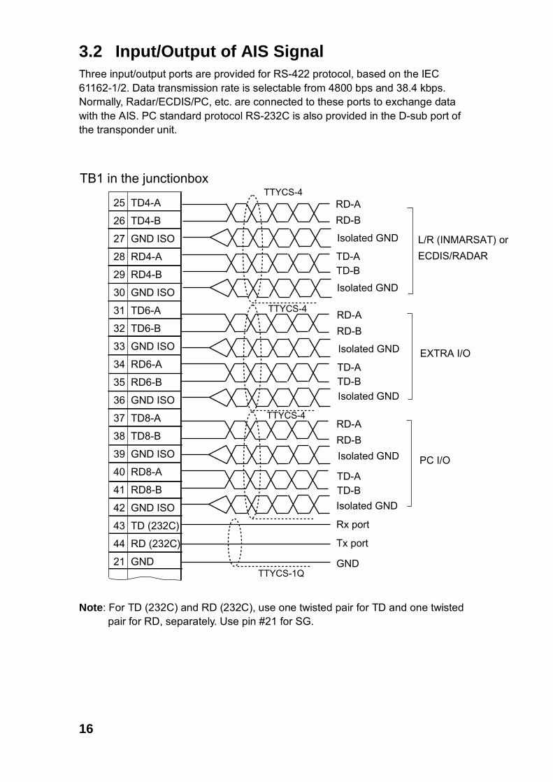
3.2 Input/Output of AIS Signal Three input/output ports are provided for RS-422 protocol, based on the IEC 61162-1/2. Data transmission rate is selectable from 4800 bps and 38.4 kbps. Normally, Radar/ECDIS/PC, etc. are connected to these ports to exchange data with the AIS. PC standard protocol RS-232C is also provided in the D-sub port of the transponder unit.
25 TD4-A
26 TD4-B
27 GND ISO
28 RD4-A
29 RD4-B
30 GND ISO
31 TD6-A
32 TD6-B
33 GND ISO
34 RD6-A
35 RD6-B
36 GND ISO
37 TD8-A
38 TD8-B
39 GND ISO
40 RD8-A
41 RD8-B
42 GND ISO
43 TD (232C)
44 RD (232C)
21 GND
TB1 in the junctionbox
L/R (INMARSAT) or
ECDIS/RADAR
TTYCS-4
RD-ATTYCS-4
RD-B
Isolated GND
TD-ATD-BIsolated GND
EXTRA I/O
TTYCS-4
PC I/O
RD-A
RD-B
Isolated GND
TD-ATD-B
Isolated GND
RD-A
RD-B
Isolated GND
TD-ATD-B
Isolated GND
Rx port
Tx port
GNDTTYCS-1Q
Note: For TD (232C) and RD (232C), use one twisted pair for TD and one twisted
pair for RD, separately. Use pin #21 for SG.
17
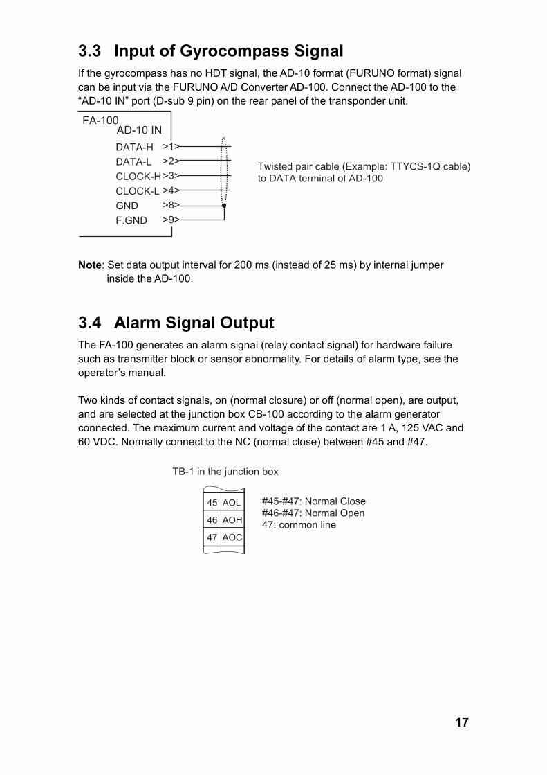
3.3 Input of Gyrocompass Signal If the gyrocompass has no HDT signal, the AD-10 format (FURUNO format) signal can be input via the FURUNO A/D Converter AD-100. Connect the AD-100 to the “AD-10 IN” port (D-sub 9 pin) on the rear panel of the transponder unit.
DATA-H DATA-L CLOCK-HCLOCK-LGNDF.GND
AD-10 INFA-100
>1>>2>>3>>4>>8>>9>
Twisted pair cable (Example: TTYCS-1Q cable) to DATA terminal of AD-100
Note: Set data output interval for 200 ms (instead of 25 ms) by internal jumper
inside the AD-100.
3.4 Alarm Signal Output The FA-100 generates an alarm signal (relay contact signal) for hardware failure such as transmitter block or sensor abnormality. For details of alarm type, see the operator’s manual. Two kinds of contact signals, on (normal closure) or off (normal open), are output, and are selected at the junction box CB-100 according to the alarm generator connected. The maximum current and voltage of the contact are 1 A, 125 VAC and 60 VDC. Normally connect to the NC (normal close) between #45 and #47.
45 AOL
46 AOH
47 AOC
TB-1 in the junction box
#45-#47: Normal Close#46-#47: Normal Open47: common line
18
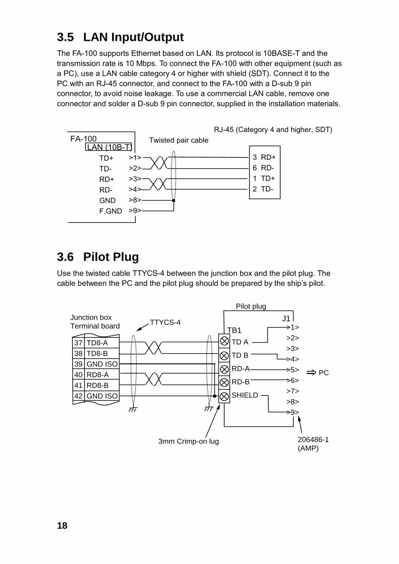
3.5 LAN Input/Output The FA-100 supports Ethernet based on LAN. Its protocol is 10BASE-T and the transmission rate is 10 Mbps. To connect the FA-100 with other equipment (such as a PC), use a LAN cable category 4 or higher with shield (SDT). Connect it to the PC with an RJ-45 connector, and connect to the FA-100 with a D-sub 9 pin connector, to avoid noise leakage. To use a commercial LAN cable, remove one connector and solder a D-sub 9 pin connector, supplied in the installation materials.
TD+ TD- RD+RD-GNDF.GND
LAN (10B-T)FA-100
>1>>2>>3>>4>>8>>9>
3 RD+6 RD-1 TD+2 TD-
Twisted pair cableRJ-45 (Category 4 and higher, SDT)
3.6 Pilot Plug Use the twisted cable TTYCS-4 between the junction box and the pilot plug. The cable between the PC and the pilot plug should be prepared by the ship’s pilot.
Junction boxTerminal board
TD A
TD B
RD-A
RD-B
SHIELD
TB1 >1>
>2>
>3>
>4>
>5>
>6>
>7>
>8>
>9>
J1
37 TD8-A
38 TD8-B
39 GND ISO
40 RD8-A
41 RD8-B
42 GND ISO
Pilot plug
TTYCS-4
3mm Crimp-on lug 206486-1(AMP)
PC

19
3.7 Jumper Setting in the Junction Box Each RS-422 RX line (on the PCB 24P0031 in the junction box) has a jumper block with 240 ohms termination resistor. The junction box is shipped with all jumper blocks connected between the #3 and #4 terminals pins, terminating RX lines with 240 ohms. Assuming that an external equipment has the output voltage of ±5 V, more than 21 mA of output current is required. If multiple equipment are connected to an output port of an external equipment, change to jumper block setting to between the #1 and #2 pins to reduce the load on the FA-100. Then, the input impedance of the RS-422 RX lines in the FA-100 becomes more than 2.4 k ohms. We recommend that you leave the connection of the jumper block between #3 and #4 pins if only the FA-100 is connected to an external equipment.
1
2
34
Jumper block (6 pcs)
Factory setting: #3-#4

20
3.8 Input/Output Sentences 1) SENSOR 1, SENSOR2, and SENSOR3 ports These ports can receive IEC61162-1/2 standard data. The transmission rate of sensor 1, 2, and 3 is selectable from 4800 bps and 38.4 kbps through the menu.
Input sentences are as follows: $xxDTM, $xxGBS, $xxGGA, $xxGLL, $xxGNS, $xxHDT $xxOSD, $xxRMC, $xxROT, $xxVBW, $xxVTG Note: The talker of the underlined sentences has priority as follows:
GN>GP>GL>LC>IN Other sentences disregard talker.
2) PC I/O, LR or ECDIS/RADAR, EXTRA I/O and EXTRA 1 I/O ports These ports can receive or output IEC61162-1/2 standard data. The transmission rate of signals is selectable from 4800 bps and 38.4 kbps through the menu. The transmission rate of the EXTRA IO port signal is fixed to 4800 bps. Input sentences are as follows:
$xxABM, $xxACA, $xxACK, $xxAIR $xxBBM, $xxDTM, $xxGBS, $xxGGA $xxGLL, $xxGNS, $xxHDT, $xxLRF $xxLRI, $xxOSD, $xxRMC, $xxROT $xxSSD, $xxVBW, $xxVSD, $xxVTG Note: The talker of the underlined sentences has priority as follows:
GN>GP>GL>LC>IN Other sentences disregard talker.
Output sentences are as follows: $AIABK, $AIACA, $AIALR, $AILRF, $AILR1, $AILR2, $AILR3, $AITXT, $AIVDM, $AIVDO

21
3.9 Changing Ship�s Mains Specifications The power supply PR-240-CE is shipped ready for connection to a 200-230 VAC ship�s mains. If the ship�s mains is 100 VAC � 115 VAC, change the tap connection and terminal board connection as below. Attach label supplied as accessories to the punch mark in the front panel according to the ship�s mains.
Ship�s mains Tap connection Terminal board connection #1 & #2
100-115 VAC SEL 115 V b
200-230 VAC SEL 230 V a
12345678
Heat sink
Tap connection (Pull out to remove)
Front
SEL115 V
SEL230 V
Top view (Cover removed)
1
2
3
100-115 VAC
1
2
3
200-230 VAC
Terminal board connection
(a) (b)
White
Black
White
Black
Punch mark
22
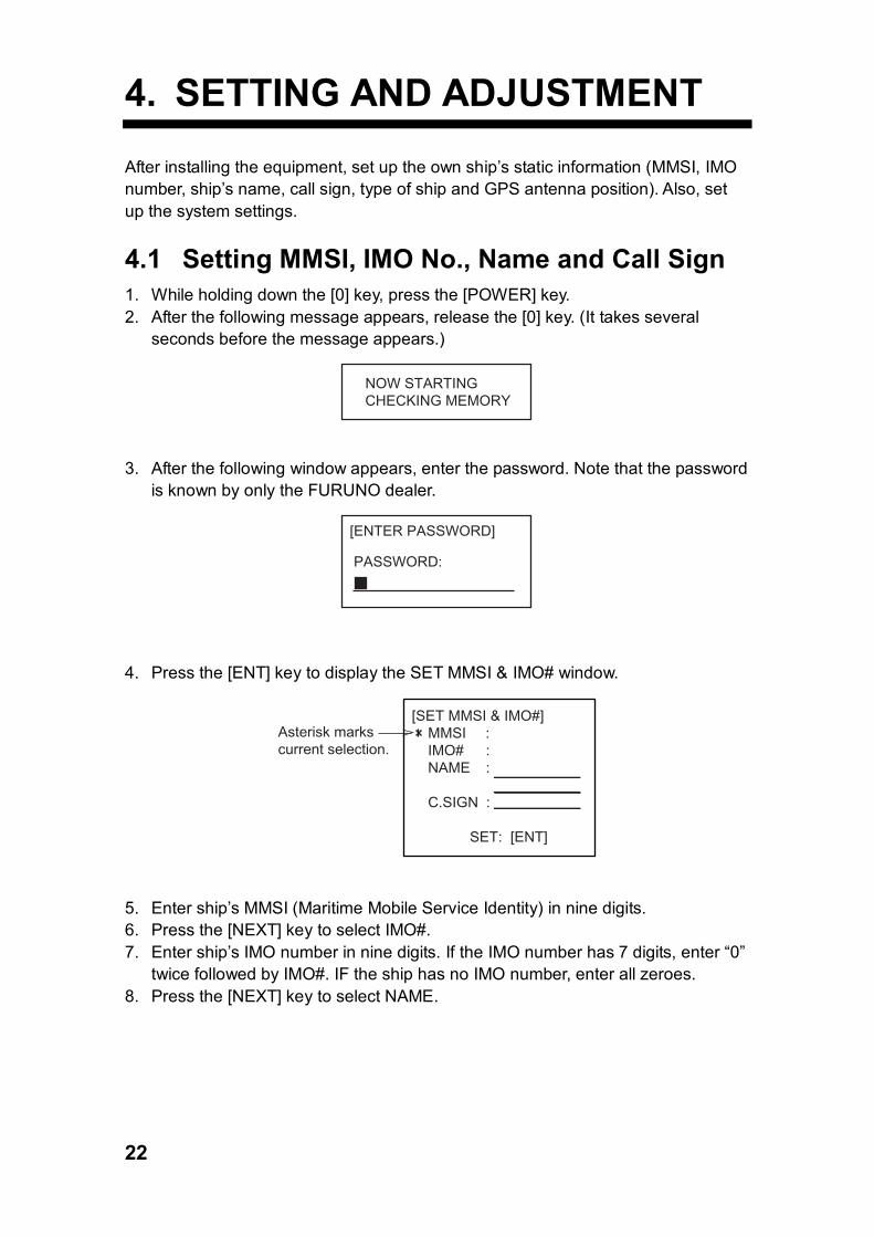
4. SETTING AND ADJUSTMENT After installing the equipment, set up the own ship’s static information (MMSI, IMO number, ship’s name, call sign, type of ship and GPS antenna position). Also, set up the system settings.
4.1 Setting MMSI, IMO No., Name and Call Sign 1. While holding down the [0] key, press the [POWER] key. 2. After the following message appears, release the [0] key. (It takes several
seconds before the message appears.)
NOW STARTINGCHECKING MEMORY
3. After the following window appears, enter the password. Note that the password
is known by only the FURUNO dealer.
[ENTER PASSWORD]
PASSWORD:
4. Press the [ENT] key to display the SET MMSI & IMO# window.
Asterisk markscurrent selection.
[SET MMSI & IMO#] MMSI : IMO# : NAME :
C.SIGN :
SET: [ENT]
5. Enter ship’s MMSI (Maritime Mobile Service Identity) in nine digits. 6. Press the [NEXT] key to select IMO#. 7. Enter ship’s IMO number in nine digits. If the IMO number has 7 digits, enter “0”
twice followed by IMO#. IF the ship has no IMO number, enter all zeroes. 8. Press the [NEXT] key to select NAME.

23
9. Enter ship�s name, using up to 20 alphanumeric characters. To switch between alphabet and numerical character, press the [SFT] key. To enter an alphabet, press corresponding key several times until desired letter is displayed. For example, if you press the [2] key continuously, the character A, B and C appear cyclically. If you want to enter the same letter or an other letter with the same key (for example, AA or AC), press the [6] key while pressing the [SFT] key, to send the cursor to the next position.
10. Press the [NEXT] key to select C.SIGN. 11. Enter call sign, using up to seven alphanumeric characters. 12. Press the [ENT] key to register data. The INIT SETTINGS sub-menu appears.

24
4.2 Setting GPS Antenna Position and Ship’s Type
1. In the INIT SETTING sub-menu, press the [6] key to open the SET ANTENNA POS window.
SET ANTENNA POS 1 INTERNAL ANT POS 2 EXTERNAL ANT POS
SET ANTENNA POS window 2. With 1 selected, press the [ENT] key. The 1 is for entering internal GPS antenna
position and 2 is for external GPS which is connected to the AIS.
[INTERNAL ANT POS]
A: 000 mB: 000 mC: 00 mD: 00 m
A
B
C D
INTERNAL ANT POS window 3. Enter locations of GPS antenna, by using the numeric keys and the [NEXT] key,
and finally press the [ENT] key. A: Distance from bow to GPS antenna position B: Distance from stern to GPS antenna position C: Distance from port to GPS antenna position D: Distance from starboard to GPS antenna position
4. Enter external GPS antenna position similar to how you entered internal GPS antenna position.
5. Press the [MENU] key to return to the INIT SETTINGS sub-menu. 6. Press the [4] key to display the SET TYPE&CREW window.
TYPE NAME
[SET TYPE&CREW] CREW : 0012 TYPE CLASS : A TYPE NO. : 0
TYPE CLASS cannotbe changed.(A = IMO type)
SET TYPE&CREW window
25
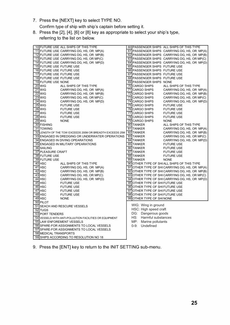
7. Press the [NEXT] key to select TYPE NO. Confirm type of ship with ship’s captain before setting it.
8. Press the [2], [4], [6] or [8] key as appropriate to select your ship’s type, referring to the list on below.
10 FUTURE USE ALL SHIPS OF THIS TYPE 60 PASSENGER SHIPS ALL SHIPS OF THIS TYPE11 FUTURE USE CARRYING DG, HS, OR MP(A) 61 PASSENGER SHIPS CARRYING DG, HS, OR MP(A)12 FUTURE USE CARRYING DG, HS, OR MP(B) 62 PASSENGER SHIPS CARRYING DG, HS, OR MP(B)13 FUTURE USE CARRYING DG, HS, OR MP(C) 63 PASSENGER SHIPS CARRYING DG, HS, OR MP(C)14 FUTURE USE CARRYING DG, HS, OR MP(D) 64 PASSENGER SHIPS CARRYING DG, HS, OR MP(D)15 FUTURE USE FUTURE USE 65 PASSENGER SHIPS FUTURE USE16 FUTURE USE FUTURE USE 66 PASSENGER SHIPS FUTURE USE17 FUTURE USE FUTURE USE 67 PASSENGER SHIPS FUTURE USE18 FUTURE USE FUTURE USE 68 PASSENGER SHIPS FUTURE USE19 FUTURE USE NONE 69 PASSENGER SHIPS NONE20 WIG ALL SHIPS OF THIS TYPE 70 CARGO SHIPS ALL SHIPS OF THIS TYPE21 WIG CARRYING DG, HS, OR MP(A) 71 CARGO SHIPS CARRYING DG, HS, OR MP(A)22 WIG CARRYING DG, HS, OR MP(B) 72 CARGO SHIPS CARRYING DG, HS, OR MP(B)23 WIG CARRYING DG, HS, OR MP(C) 73 CARGO SHIPS CARRYING DG, HS, OR MP(C)24 WIG CARRYING DG, HS, OR MP(D) 74 CARGO SHIPS CARRYING DG, HS, OR MP(D)25 WIG FUTURE USE 75 CARGO SHIPS FUTURE USE26 WIG FUTURE USE 76 CARGO SHIPS FUTURE USE27 WIG FUTURE USE 77 CARGO SHIPS FUTURE USE28 WIG FUTURE USE 78 CARGO SHIPS FUTURE USE29 WIG NONE 79 CARGO SHIPS NONE30 FISHING 80 TANKER ALL SHIPS OF THIS TYPE31 TOWING 81 TANKER CARRYING DG, HS, OR MP(A)32 LENGTH OF THE TOW EXCEEDS 200M OR BREADTH EXCEEDS 25M 82 TANKER CARRYING DG, HS, OR MP(B)33 ENGAGED IN DREDGING OR UNDERWATER OPERATIONS 83 TANKER CARRYING DG, HS, OR MP(C)34 ENGAGED IN DIVING OPEARATIONS 84 TANKER CARRYING DG, HS, OR MP(D)35 ENGAGED IN MILITARY OPEARATIONS 85 TANKER FUTURE USE36 SAILING 86 TANKER FUTURE USE37 PLEASURE CRAFT 87 TANKER FUTURE USE38 FUTURE USE 88 TANKER FUTURE USE39 FUTURE USE 89 TANKER NONE40 HSC ALL SHIPS OF THIS TYPE 90 OTHER TYPE OF SHI ALL SHIPS OF THIS TYPE41 HSC CARRYING DG, HS, OR MP(A) 91 OTHER TYPE OF SHI CARRYING DG, HS, OR MP(A)42 HSC CARRYING DG, HS, OR MP(B) 92 OTHER TYPE OF SHI CARRYING DG, HS, OR MP(B)43 HSC CARRYING DG, HS, OR MP(C) 93 OTHER TYPE OF SHI CARRYING DG, HS, OR MP(C)44 HSC CARRYING DG, HS, OR MP(D) 94 OTHER TYPE OF SHI CARRYING DG, HS, OR MP(D)45 HSC FUTURE USE 95 OTHER TYPE OF SHI FUTURE USE46 HSC FUTURE USE 96 OTHER TYPE OF SHI FUTURE USE47 HSC FUTURE USE 97 OTHER TYPE OF SHI FUTURE USE48 HSC FUTURE USE 98 OTHER TYPE OF SHI FUTURE USE49 HSC NONE 99 OTHER TYPE OF SHI NONE50 PILOT51 SEACH AND RESCURE VESSELS52 TUGS53 PORT TENDERS54 VESSELS WITH ANTI-POLUUTION FACILITIES OR EQUIPMENT
55 LAW ENFOREMENT VESSELS56 SPARE-FOR ASSIGNMENTS TO LOCAL VESSELS57 SPARE-FOR ASSIGNMENTS TO LOCAL VESSELS58 MEDICAL TRANSPORTS59 SHIPS ACCORDING TO RESOLUTION NO 18
WIG: Wing in groundHSC: High speed craftDG: Dangerous goodsHS: Harmful substancesMP: Marine pollutants0-9: Undefined
9. Press the [ENT] key to return to the INIT SETTING sub-menu.
26
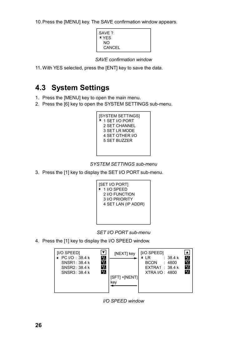
10. Press the [MENU] key. The SAVE confirmation window appears.
SAVE ? YES NO CANCEL
SAVE confirmation window
11. With YES selected, press the [ENT] key to save the data.
4.3 System Settings 1. Press the [MENU] key to open the main menu. 2. Press the [6] key to open the SYSTEM SETTINGS sub-menu.
[SYSTEM SETTINGS] 1 SET I/O PORT 2 SET CHANNEL 3 SET LR MODE 4 SET OTHER I/O 5 SET BUZZER
SYSTEM SETTINGS sub-menu
3. Press the [1] key to display the SET I/O PORT sub-menu.
[SET I/O PORT] 1 I/O SPEED 2 I/O FUNCTION 3 I/O PRIORITY 4 SET LAN (IP ADDR)
SET I/O PORT sub-menu
4. Press the [1] key to display the I/O SPEED window.
[I/O SPEED] LR : 38.4 k BCON : 4800 EXTRA1 : 38.4 k XTRA I/O : 4800 1 2
+-
+-
+-+-
[I/O SPEED] PC I/O : 38.4 k SNSR1: 38.4 k SNSR2: 38.4 k SNSR3: 38.4 k 1 2
+-
+-
+-+-
[NEXT] key
[SFT] +[NENT] key
I/O SPEED window
27
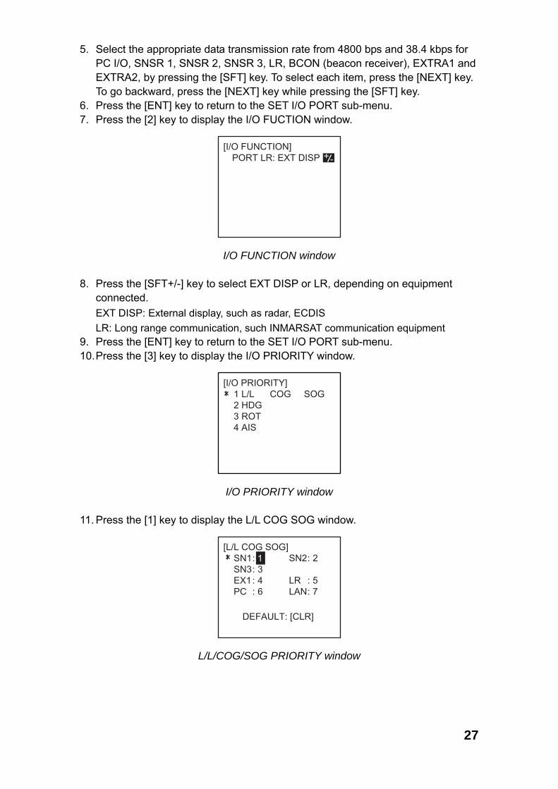
5. Select the appropriate data transmission rate from 4800 bps and 38.4 kbps for PC I/O, SNSR 1, SNSR 2, SNSR 3, LR, BCON (beacon receiver), EXTRA1 and EXTRA2, by pressing the [SFT] key. To select each item, press the [NEXT] key. To go backward, press the [NEXT] key while pressing the [SFT] key.
6. Press the [ENT] key to return to the SET I/O PORT sub-menu. 7. Press the [2] key to display the I/O FUCTION window.
[I/O FUNCTION] PORT LR: EXT DISP +-
I/O FUNCTION window 8. Press the [SFT+/-] key to select EXT DISP or LR, depending on equipment
connected. EXT DISP: External display, such as radar, ECDIS LR: Long range communication, such INMARSAT communication equipment
9. Press the [ENT] key to return to the SET I/O PORT sub-menu. 10. Press the [3] key to display the I/O PRIORITY window.
[I/O PRIORITY] 1 L/L COG SOG 2 HDG 3 ROT 4 AIS
I/O PRIORITY window 11. Press the [1] key to display the L/L COG SOG window.
SN2: 2
LR : 5LAN: 7
[L/L COG SOG] SN1: SN3: 3 EX1: 4 PC : 6
DEFAULT: [CLR]
1
L/L/COG/SOG PRIORITY window
28
12. Set L/L position, COG and SOG data priority with the numeric keys according to sensors connected.
COG: Course over ground SOG: Speed over ground 13. Press the [ENT] key to return to the I/O PRIORITY window.
Note: If you have entered 8, 9 or the same value for more than one item at step
12, the following error message appears. In this case, press the [ENT] key and set the priority correctly.
[ERROR] CAN NOT INPUT SAME VALUE !
ESC: [ENT]
[ERROR] OUT OF RANGE ! PRIORITY: 1-7
ESC: [ENT]
ERROR message
14. Set the priority for HDG and ROT similar to how you did for “L/L COG SOG”. The priority of heading data entered from the AD-10 IN port is the lowest.
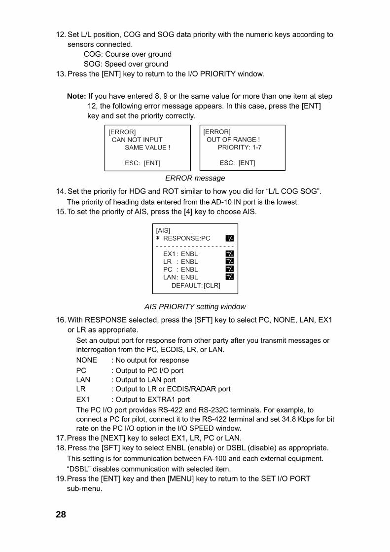
15. To set the priority of AIS, press the [4] key to choose AIS.
[AIS] RESPONSE:PC- - - - - - - - - - - - - - - - - - - - EX1: ENBL LR : ENBL PC : ENBL LAN: ENBL
+-
+-
+-
+-+-
DEFAULT: [CLR]
AIS PRIORITY setting window
16. With RESPONSE selected, press the [SFT] key to select PC, NONE, LAN, EX1 or LR as appropriate. Set an output port for response from other party after you transmit messages or
interrogation from the PC, ECDIS, LR, or LAN. NONE : No output for response PC : Output to PC I/O port
LAN : Output to LAN port LR : Output to LR or ECDIS/RADAR port
EX1 : Output to EXTRA1 port The PC I/O port provides RS-422 and RS-232C terminals. For example, to
connect a PC for pilot, connect it to the RS-422 terminal and set 34.8 Kbps for bit rate on the PC I/O option in the I/O SPEED window.
17. Press the [NEXT] key to select EX1, LR, PC or LAN. 18. Press the [SFT] key to select ENBL (enable) or DSBL (disable) as appropriate.
This setting is for communication between FA-100 and each external equipment. “DSBL” disables communication with selected item.
19. Press the [ENT] key and then [MENU] key to return to the SET I/O PORT sub-menu.
29
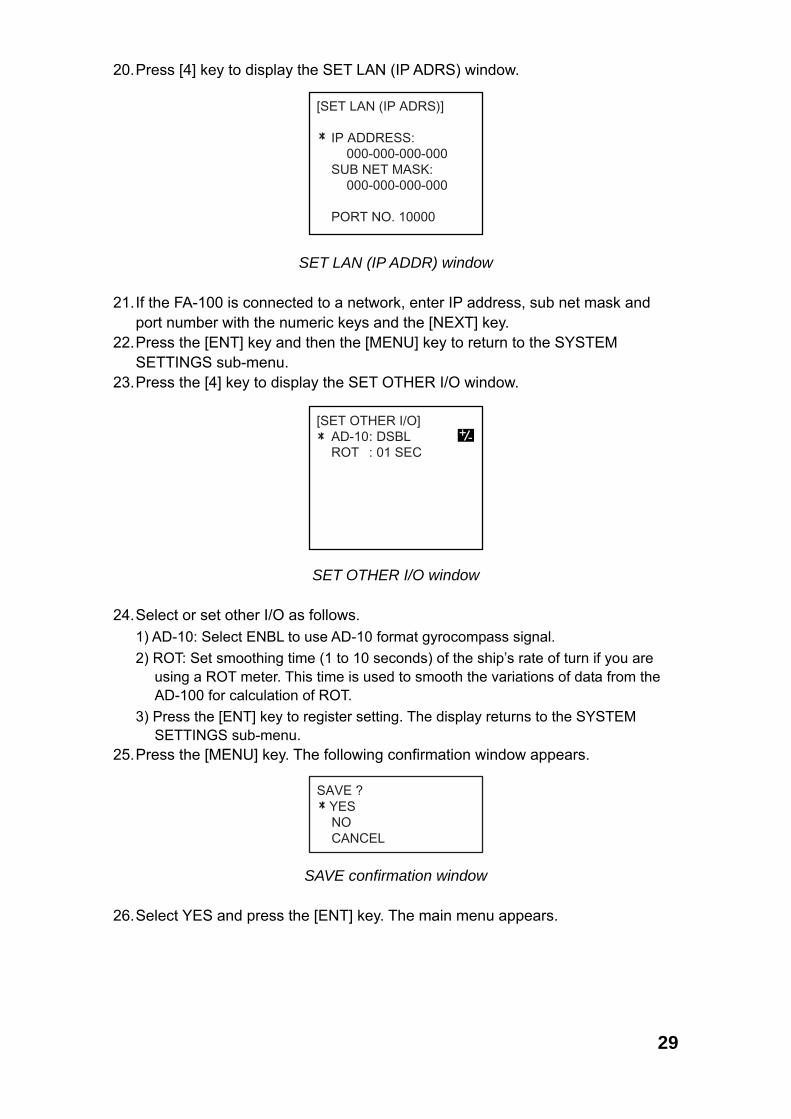
20. Press [4] key to display the SET LAN (IP ADRS) window.
[SET LAN (IP ADRS)]
IP ADDRESS:000-000-000-000
SUB NET MASK:000-000-000-000
PORT NO. 10000
SET LAN (IP ADDR) window 21. If the FA-100 is connected to a network, enter IP address, sub net mask and
port number with the numeric keys and the [NEXT] key. 22. Press the [ENT] key and then the [MENU] key to return to the SYSTEM
SETTINGS sub-menu. 23. Press the [4] key to display the SET OTHER I/O window.
[SET OTHER I/O] AD-10: DSBL ROT : 01 SEC
+ -
SET OTHER I/O window 24. Select or set other I/O as follows.
1) AD-10: Select ENBL to use AD-10 format gyrocompass signal. 2) ROT: Set smoothing time (1 to 10 seconds) of the ship’s rate of turn if you are
using a ROT meter. This time is used to smooth the variations of data from the AD-100 for calculation of ROT.
3) Press the [ENT] key to register setting. The display returns to the SYSTEM SETTINGS sub-menu.
25. Press the [MENU] key. The following confirmation window appears.
SAVE ? YES NO CANCEL
SAVE confirmation window 26. Select YES and press the [ENT] key. The main menu appears.

This page is intentionally left blank.
PACKING LISTPACKING LISTPACKING LISTPACKING LIST 24AA-X-9854 -1
FA-100-J/E,FA-100-J/E-HKFA-100-J/E,FA-100-J/E-HKFA-100-J/E,FA-100-J/E-HKFA-100-J/E,FA-100-J/E-HK
N A M E O U T L I N E DESCRIPTION/CODE № Q'TY
1/1
ユニットユニットユニットユニット UNITUNITUNITUNITトランスポンダ部
TRANSPONDER UNIT
FA-100
000-053-889
1
**
工事材料工事材料工事材料工事材料 INSTALLATION MATERIALSINSTALLATION MATERIALSINSTALLATION MATERIALSINSTALLATION MATERIALS CP24-00102CP24-00102CP24-00102CP24-00102コネクタフード(XM2)
HOUSING CASE
XM2S-0912
000-145-422
1
ケーブル組品MJ
CABLE ASSY.
MJ-A3SPF0015-035
000-137-340
1
コネクタ(XM2)
CONNECTOR(XM2)
XM2A-0901
000-111-785
1
図書図書図書図書 DOCUMENTDOCUMENTDOCUMENTDOCUMENT装備要領書
INSTALLATION MANUAL
IMJ-44170-*
000-809-324
1
**
取扱説明書
OPERATOR'S MANUAL
OMJ-44170-*
000-809-322
1
**
1.コ-ド番号末尾の[**]は、選択品の代表型式/コートを表します。
CODE NUMBER ENDED BY "**" INDICATES THE NUMBER OF TYPICAL MATERIAL.
(略図の寸法は、参考値です。 DIMENSIONS IN DRAWING FOR REFERENCE ONLY.)(略図の寸法は、参考値です。 DIMENSIONS IN DRAWING FOR REFERENCE ONLY.)(略図の寸法は、参考値です。 DIMENSIONS IN DRAWING FOR REFERENCE ONLY.)(略図の寸法は、参考値です。 DIMENSIONS IN DRAWING FOR REFERENCE ONLY.)
24AA-X-9854

PACKING LISTPACKING LISTPACKING LISTPACKING LIST 24AA-X-9851 -4
CB-100-A、CB-100-A-HKCB-100-A、CB-100-A-HKCB-100-A、CB-100-A-HKCB-100-A、CB-100-A-HK
N A M E O U T L I N E DESCRIPTION/CODE № Q'TY
1/1
ユニットユニットユニットユニット UNITUNITUNITUNIT接続箱
JUNCTION BOX UNIT
CB-100-A
000-053-873
1
**
工事材料工事材料工事材料工事材料 INSTALLATION MATERIALSINSTALLATION MATERIALSINSTALLATION MATERIALSINSTALLATION MATERIALS CP05-08701CP05-08701CP05-08701CP05-08701+トラスタッピンネジ
+TAPPING SCREW
5X20 SUS304 1シュ
000-802-081
4
1.コ-ド番号末尾の[**]は、選択品の代表型式/コートを表します。
DOUBLE ASTERISK DENOTES COMMONLY USED EQUIPMENT.
(略図の寸法は、参考値です。 DIMENSIONS IN DRAWING FOR REFERENCE ONLY.)(略図の寸法は、参考値です。 DIMENSIONS IN DRAWING FOR REFERENCE ONLY.)(略図の寸法は、参考値です。 DIMENSIONS IN DRAWING FOR REFERENCE ONLY.)(略図の寸法は、参考値です。 DIMENSIONS IN DRAWING FOR REFERENCE ONLY.)
24AA-X-9851

PACKING LIST 24AA-X-9853 -3
GVA-100
N A M E O U T L I N E DESCRIPTION/CODE № Q'TY
1/1
ユニット UNIT
複合空中線部
GPS/VHF COMBINED ANTENNA
GVA-100
000-053-810
1
工事材料 INSTALLATION MATERIALS CP24-00141
コネクタ(N)
CONNECTOR
N-P-8DFB 座金付き
000-140-463
2
コンベックス
PLASTIC BAND
CV-200HT
000-809-226
2
アンテナ取付金具
ANTENNA FIXING BRACKET
24-003-3015-0
100-302-670
2
ミガキ平座金
FLAT WASHER
M8 SUS304
000-864-130
4
六角ナット 1種
HEX.NUT
M8 SUS304
000-863-110
8
(略図の寸法は、参考値です。 DIMENSIONS IN DRAWING FOR REFERENCE ONLY.)
24AA-X-9853
CODE NO.CODE NO.CODE NO.CODE NO. 004-365-780TYPETYPETYPETYPE CP20-01111
略 図OUTLINE
名 称 NAME
数量Q'TY
用途/備考REMARKS
番 号 NO.
型名/規格DESCRIPTIONS
1/1
-1
INSTALLATION MATERIALS
工事材料表工事材料表工事材料表工事材料表 マスト取付金具 MAST FIXTURE
20AG-X-9403
パイプ
PIPE
20-007-3011-2
1
100-183-262
1
CODE NO.
取付補助金具
INSTALLING SPACER
20-007-3012-1
1
100-183-271
2
CODE NO.
パーカークランプ
HOSE CLAMP
NO.6348 SUS303
2
000-805-906
3
CODE NO.
(略図の寸法は、参考値です。 DIMENSIONS IN DRAWING FOR REFERENCE ONLY.)(略図の寸法は、参考値です。 DIMENSIONS IN DRAWING FOR REFERENCE ONLY.)(略図の寸法は、参考値です。 DIMENSIONS IN DRAWING FOR REFERENCE ONLY.)(略図の寸法は、参考値です。 DIMENSIONS IN DRAWING FOR REFERENCE ONLY.)
FURUNO ELECTRIC CO .,LTD.
20AG-X-9403

PACKING LISTPACKING LISTPACKING LISTPACKING LIST 24AA-X-9852 -5
PR-240-CEPR-240-CEPR-240-CEPR-240-CE
N A M E O U T L I N E DESCRIPTION/CODE № Q'TY
1/1
ユニットユニットユニットユニット UNITUNITUNITUNIT
AC-DC電源
POWER SUPPLY UNIT
PR-240-CE
000-053-879
1
工事材料工事材料工事材料工事材料 INSTALLATION MATERIALSINSTALLATION MATERIALSINSTALLATION MATERIALSINSTALLATION MATERIALS CP24-00151CP24-00151CP24-00151CP24-00151
PR-240-CE電源変更手順書
POWER MODIFICATION PROCEDURES
C52-00205-A
000-147-013
1
デンゲンハリマーク
POWER LABEL
24-003-4101-3
100-299-773
1
+トラスタッピンネジ
+TAPPING SCREW
4X16 SUS304 1シュ
000-802-080
4
(略図の寸法は、参考値です。 DIMENSIONS IN DRAWING FOR REFERENCE ONLY.)(略図の寸法は、参考値です。 DIMENSIONS IN DRAWING FOR REFERENCE ONLY.)(略図の寸法は、参考値です。 DIMENSIONS IN DRAWING FOR REFERENCE ONLY.)(略図の寸法は、参考値です。 DIMENSIONS IN DRAWING FOR REFERENCE ONLY.)
24AA-X-9852
CODE NO.CODE NO.CODE NO.CODE NO.
TYPETYPETYPETYPE
略 図OUTLINE
名 称 NAME
数量Q'TY
用途/備考REMARKS
番 号 NO.
型名/規格DESCRIPTIONS
1/1
-1
INSTALLATION MATERIALS
工事材料表工事材料表工事材料表工事材料表 GP-80,GP-90,SC-55,GP-3500/F GP-1850,GP-1650,FA-100,GP-1640/F SC-60/120,GD/GP-280/680/380
20AG-X-9404
アンテナケーブル組品
ANTENNA CABLE ASSY.
8D-FB-CV *30M*
1
選択 TO BE SELECTED
000-111-547
1
CODE NO.
ケーブル組品
CABLE ASSY.
8D-FB-CV *50M*
1
選択 TO BE SELECTED
000-117-599
2
CODE NO.
(略図の寸法は、参考値です。 DIMENSIONS IN DRAWING FOR REFERENCE ONLY.)(略図の寸法は、参考値です。 DIMENSIONS IN DRAWING FOR REFERENCE ONLY.)(略図の寸法は、参考値です。 DIMENSIONS IN DRAWING FOR REFERENCE ONLY.)(略図の寸法は、参考値です。 DIMENSIONS IN DRAWING FOR REFERENCE ONLY.)FURUNO ELECTRIC CO .,LTD.
20AG-X-9404

CODE NO.CODE NO.CODE NO.CODE NO. 004-372-420TYPETYPETYPETYPE CP20-01701
略 図OUTLINE
名 称 NAME
数量Q'TY
用途/備考REMARKS
番 号 NO.
型名/規格DESCRIPTIONS
1/1
-1
INSTALLATION MATERIALS
工事材料表工事材料表工事材料表工事材料表
20AG-X-9405
変換ケーブル組品
CONVERT CABLE ASSY.
NJ-TP-3DXV-1
2
000-123-809
1
CODE NO.
ビニールテープ
VINYL TAPE
NO360 02X19X10000 クロ エスロン
1
000-835-215
2
CODE NO.
コネクタ(N)
CONNECTOR
N-P-8DFB
1
000-111-549
3
CODE NO.
絶縁テープ
SELF-BONDING TAPE
Uテープ 0.5X19X5M
1
000-800-985
4
CODE NO.
(略図の寸法は、参考値です。 DIMENSIONS IN DRAWING FOR REFERENCE ONLY.)(略図の寸法は、参考値です。 DIMENSIONS IN DRAWING FOR REFERENCE ONLY.)(略図の寸法は、参考値です。 DIMENSIONS IN DRAWING FOR REFERENCE ONLY.)(略図の寸法は、参考値です。 DIMENSIONS IN DRAWING FOR REFERENCE ONLY.)FURUNO ELECTRIC CO .,LTD.
20AG-X-9405

CODE NO.CODE NO.CODE NO.CODE NO. 004-365-780TYPETYPETYPETYPE CP20-01111
略 図OUTLINE
名 称 NAME
数量Q'TY
用途/備考REMARKS
番 号 NO.
型名/規格DESCRIPTIONS
1/1
-1
INSTALLATION MATERIALS
工事材料表工事材料表工事材料表工事材料表 マスト取付金具 MAST FIXTURE
20AG-X-9403
パイプ
PIPE
20-007-3011-2
1
100-183-262
1
CODE NO.
取付補助金具
INSTALLING SPACER
20-007-3012-1
1
100-183-271
2
CODE NO.
パーカークランプ
HOSE CLAMP
NO.6348 SUS303
2
000-805-906
3
CODE NO.
(略図の寸法は、参考値です。 DIMENSIONS IN DRAWING FOR REFERENCE ONLY.)(略図の寸法は、参考値です。 DIMENSIONS IN DRAWING FOR REFERENCE ONLY.)(略図の寸法は、参考値です。 DIMENSIONS IN DRAWING FOR REFERENCE ONLY.)(略図の寸法は、参考値です。 DIMENSIONS IN DRAWING FOR REFERENCE ONLY.)
FURUNO ELECTRIC CO .,LTD.
20AG-X-9403


3 41 2 5 6
TYPE
名前
NAMEkg
DWG. No.
SCALE
APPROVED
DRAWN
CHECKED
MASS
FA-100
国際船舶自動識別装置
相互結線図
INTERCONNECTION DIAGRAM
U-AIS TRANSPONDER
C
B
D
A
1234
IEC61162-1/2
FA-100
J2
GPS-ANT
VHF-ANT
J1
ANTE
N-P-8DFB
NJ-TP-3DXV-11m,φ5.3
123
(+)(-)GND
*DPYC-1.5AC IN (+)
(-)DC OUT
φ1,50/60Hz100-115/200-230VAC
(02S4100-0)
SNSR3
AC/DC電源ユニットAC/DC POWER SUPPLY
UNIT
POWER
24P0020
J1(FM-C3MR)MJ-A3SPFDMJ-A3SPF0015,3.5m,φ6
シロクロ
WHTBLK
J1
IEC61162-1: 4800BPS
IEC61162-2: 38.4KBPS
IEC61162-4: 10BASE-T
RG-10/UY *1 M-P-7
TRANSPONDER UNITTD3-ATD3-BRD3-ARD3-B
*7
トランスポンダ部
CO-0.2x2P: CO-SPEVV-SB-C 0.2x2P,φ10.5
5678
IEC61162-1/2
SNSR2 TD2-ATD2-BRD2-ARD2-B
9101112
IEC61162-1/2
SNSR1TD1-BRD1-ARD1-B
TD1-A
13141516
RTCM SC-104
BEACON TD5-ATD5-BRD5-ARD5-B
17181920
21222324
IEC61162-1/2
TD4-ATD4-BRD4-ARD4-B
LR OR ECDIS/RADAR
IEC61162-1/2
TD6-ATD6-BRD6-ARD6-B
EXTRA1 I/O
252627282930
TDRD
TD8-ATD8-BRD8-ARD8-B
(RS-232C)
(RS-422)
PC I/O
31323334353637
GNDFG
NC
(CONTACT SIG.)
1PPSIN
ALARM OUT
BLU/RED1BLU/BLK1PNK/RED1
アオ/アカ1アオ/クロ1モモ/アカ1モモ/クロ1
P
PPNK/BLK1GRN/RED1ミドリ/アカ1GRN/BLK1ミドリ/クロ1
ダイ/アカ1ダイ/クロ1
ORG/RED1ORG/BLK1
P
P
ハイ/アカ1
アオ/アカ2アオ/クロ2
GRY/RED1
BLU/BLK2BLU/RED2
P
ハイ/クロ1 GRY/BLK1P
234
1
5678910
P
P
モモ/アカ2モモ/クロ2ミドリ/アカ2ミドリ/クロ2
GRN/RED2GRN/BLK2
PNK/RED2PNK/BLK2
P
P
P
P
ダイ/アカ2ダイ/クロ2ハイ/アカ2
ORG/RED2ORG/BLK2GRY/RED2
ハイ/クロ2 GRY/BLK2
アオ/アカ3アオ/クロ3モモ/アカ3
BLU/RED3BLU/BLK3PNK/RED3
モモ/クロ3 BLU/BLK3
234
1
56789101112
GRY/RED3ダイ/クロ3 ORG/BLK3ダイ/アカ3 ORG/RED3ミドリ/クロ3 GRN/BLK3ミドリ/アカ3 GRN/RED3
ハイ/アカ3
P
P
ハイ/クロ3 GRY/BLK3
234
1
567891011121314ミドリ/クロ4 GRN/BLK4
モモ/クロ4モモ/アカ4 PNK/RED4アオ/クロ4 BLU/BLK4アオ/アカ4 BLU/RED4
P
PPNK/BLK4
ミドリ/アカ4 GRN/RED4P
P
12345678910111213141516171819202122
242526272829303132333435363738394041
TD3-ATD3-B
RD3-ARD3-B
TD2-ATD2-B
RD2-ARD2-B
42
TD1-ATD1-B
RD1-ARD1-B
TD5-ATD5-B
RD5-A23RD5-B
接続箱JUNCTION BOX
CB-100
RD4-ARD4-B
TD8-ATD8-B
TD4-ATD4-B
TD6-ATD6-B
RD6-ARD6-B
RD8-ARD8-B
1234
J3LATX-HLATX-LLARX-HLARX-L
IEC61162-4
89FG
D-SUB 9P
123489FG
D-SUB 9P
12
89FG
67
LOGLOG-GPRTXPRRX
J4
J5
GDAT-HGDAT-LGCK-HGCK-L
*6 OR CO-0.2x2PAD-100 GYRO*6
12
GNDFG
89
J2TD7-ATD7-B
D-SUB 9P
OR CO-0.2x2PIEC61162-1
12
89FG
J6GPEXT-AGPEXT-BGPEXR-AGPEXR-B
GND
GND
GND
GND
TTYCS-1Q,φ13.5 *1
TTYCS-1Q,φ13.5 *1
NOT USED
(10BASE-T)
EXTRA I/O
LAN(10B-T)
24P0025
AD-10 IN
LAN CABLE *1
NOT USED
AUX-1
AUX-2
(MAX.30m)
XM2A-3710
1
2
3,4
1
2
3,4
1
2
3,4
GNDISO
GNDISO
GNDISO
GNDISO
GNDISO
GNDISO
GND
GND
GNDISO
GNDISO
GNDISO
GNDISO
GNDISO
GNDISO
保護アース
PR-240-CE *2
24S0058,3.3m
IS NOT AVAILABLE.
*5: ROT (RATE OF TURN) INDICATOR CAN BE CONNECTED IF PROVIDED.
*6: GYRO CONVERTOR AD-100 IS REQUIRED WHEN GYRO SIGNAL (IEC61162)
NOTE:
*2: OPTION.
*3: POSITION DATA (L/L) IS REQUIRED BY EXTERNAL GPS RECEIVER.
*4: SPEED LOG IS NOT REQUIRED WHEN SOG (SPEED OVER GROUND) AND
COG (COURSE OVER GROUND) DATA ARE FED BY EXTERNAL GPS RECEIVER.
*1: SHIPYARD SUPPLY.
*7: MAX. CABLE LENGTH IS 0.5m FOR 12 VDC SPECIFICATIONS.
注記
*2)オプション。
*3)外部GPS受信機からのL/Lデータ入力が必要。
*4)SOG、COGが外部GPSから出力可能な場合は不要。
*5)ROTは接続可能な場合のみ。
*1)造船所手配。
*7)12V仕様の場合、ケーブル最大長は0.5m。
*8)AMP社製。
*8: SUPPLIED BY AMP INC.
8D-FB-CV,30/50m(L>20m) *2
NJ-TP-3DXV-1
1m,φ5.3
0.2m
N-P-8DFB
TNC-J-3
RG-10/UY,MAX.20m *1
VHFアンテナVHF ANTENNA
SELECT選択
N-P-8DFB
GSC-001
N-J-3
FAB-151D
0.8m
RG-10/UY,MAX.20m *18D-FB-CV,30/50m(L>20m)
*2
N-J-3N-P-8DFB
1m
VHF-ANT1mM-P-3
GPS-ANT1m
TNC-P-3DB-1
分配器DISTRI-BUTOR
SHIP'S MAIN ANDEMERGENCY SOURCE
非常電源船内主電源及び
P
P
GYRO OR[IMO Res. MSC.116(73)]THDOR CO-0.2x2P (MAX.30m)
TTYCS-1Q,φ13.5 *1
DGPS受信機OR CO-0.2x2PTTYCS-1Q,φ13.5 *1
(MAX.30m)DGPS BEACON RECEIVER
OR CO-0.2x2PROT OR LOG*5 *4
(MAX.30m)TTYCS-1Q,φ13.5 *1
(MAX.30m)LONG RANGE COMMUNICATION ORRADAR/ECDIS
(MAX.30m)
TTYCS-4,φ16 *1
TTYCS-4,φ16 *1
TTYCS-4,φ16 *1
GPSEXTERNAL
*3OR CO-0.2x2P (MAX.30m)TTYCS-1Q,φ13.5 *1
P
P
P
P
P
P
12-24VDC
PE, V-2.0SQ *1
FAB-151D
J1
J3
J2
CATEGORY 4 OR ABOVE
M-P-7
34
ALOLALOHALOC
TAKAHASHI.T
EXTRA I/O (IEC61162-1/2)
(MAX.30m)
LANEXTERNAL EQUIPMENT(IEC61162-1)
4344454647481PPSIN
AOLAOHAOC
TD(232C)RD(232C)
ALARMOR CO-0.2x2PTTYCS-1Q,φ13.5 *1
24P0031
TTYCS-1Q,φ13.5 *1(MAX.15m) PC I/O (RS-232C)
12345
14569SHIELD
TX ATX ATX BRX ARX B
206485206486-1*1 *8
パイロットプラグユニットPILOT PLUG UNITOP24-3 *2
PC(MAX.30m)
C4417-C02- K
K.MIYAZAWA
GSC-001
GPSアンテナGPS ANTENNA
GPA-017SOR
*6)AD-10フォーマット(GYRO-IEC61162がないときに必要)
Apr. 16 '04
GVA-100
複合空中線部GPS/VHF ANTENNA
OR150M-W2VN
OR150M-W2VN
*2
*2