f900ex easy 02-70-00 ata 70 – engines codde 1 · pdf fileata 70 – engines table of...
TRANSCRIPT

F900EX EASY 02-70-00
CODDE 1 PAGE 1 / 2
DGT91832
ATA 70 – ENGINES TABLE OF CONTENTS
ISSUE 4
DASSAULT AVIATION Proprietary Data
02-70 ATA 70 – ENGINES
02-70-00 TABLE OF CONTENTS
02-70-05 GENERAL
Introduction Sources Engines location
02-70-10 DESCRIPTION
Introduction Major components Operating principle Engine system Thrust reverser Automatic engine control Fire protection
02-70-15 CONTROL AND INDICATION
Control Indication
02-70-20 SYSTEM PROTECTION
Circuit breakers
02-70-25 NORMAL OPERATION
Engine auto-starting (DEEC AUTO mode) Engine shutdown
02-70-30 ABNORMAL OPERATION
Engine manual start and motoring CAS messages

02-70-00 F900EX EASY
PAGE 2 / 2 CODDE 1
ISSUE 4
ATA 70 – ENGINES TABLE OF CONTENTS
DGT91832
DASSAULT AVIATION Proprietary Data
INTENTIONALLY LEFT BLANK

F900EX EASY 02-70-05
CODDE 1 PAGE 1 / 4
DGT91832
ATA 70 – ENGINES GENERAL
ISSUE 4
DASSAULT AVIATION Proprietary Data
INTRODUCTION
The Falcon 900EX EASy is powered by three HONEYWELL TFE731-60 engines, automatically controlled by dedicated computers.
Each engine is rated at approximately 5,000 lb (2,224 daN) of thrust at sea level with an outside ambient temperature up to 32°C (89°F) and an ambient pressure of 1,013 hPa (29.92 inHg).
The Maximum Continuous Thrust is 1,112 lb at FL 400 and Mach 0.8 in ISA conditions.

02-70-05 F900EX EASY
PAGE 2 / 4 CODDE 1
ISSUE 4
ATA 70 – ENGINES GENERAL
DGT91832
DASSAULT AVIATION Proprietary Data
FIGURE 02-70-05-00 FLIGHT DECK OVERVIEW

F900EX EASY 02-70-05
CODDE 1 PAGE 3 / 4
DGT91832
ATA 70 – ENGINES GENERAL
ISSUE 4
DASSAULT AVIATION Proprietary Data
SOURCES
ELECTRICAL POWER Engine start or in-flight ignition requires electrical power:
- batteries assisted, if needed, by Auxiliary Power Unit
- Ground Power Unit
FUEL Refer to CODDE 1 / Chapter 02 / ATA 28.
HYDRAULIC POWER Thrust reverser operation requires HYD 2 system
ENGINES LOCATION
The engines are installed in a conventional tri-jet configuration:
- the No 1 and No 3 engines are pylon-mounted on the left and right sides of the rear fuselage,
- the No 2 engine is mounted internally within aft section of the fuselage.
A thrust reverser is installed on the No 2 engine only.
FIGURE 02-70-05-01 ENGINES LOCATION

02-70-05 F900EX EASY
PAGE 4 / 4 CODDE 1
ISSUE 4
ATA 70 – ENGINES GENERAL
DGT91832
DASSAULT AVIATION Proprietary Data
INTENTIONALLY LEFT BLANK

F900EX EASY 02-70-10
CODDE 1 PAGE 1 / 10
DGT91832
ATA 70 – ENGINES DESCRIPTION
ISSUE 4
DASSAULT AVIATION Proprietary Data
INTRODUCTION
The TFE731-60 is an axial flow turbofan engine.
Each engine incorporates lubrication, fuel, and ignition systems.
The No 2 engine is equipped with a thrust reverser.
The engines are automatically controlled by dedicated computers and share a common detection and fire extinguishing system with one of the other engines.
FIGURE 02-70-10-00 TFE731-60 TURBOFAN ENGINE
02-70-10 F900EX EASY
PAGE 2 / 10 CODDE 1
ISSUE 4
ATA 70 – ENGINES DESCRIPTION
DGT91832
DASSAULT AVIATION Proprietary Data
MAJOR COMPONENTS
INTRODUCTION
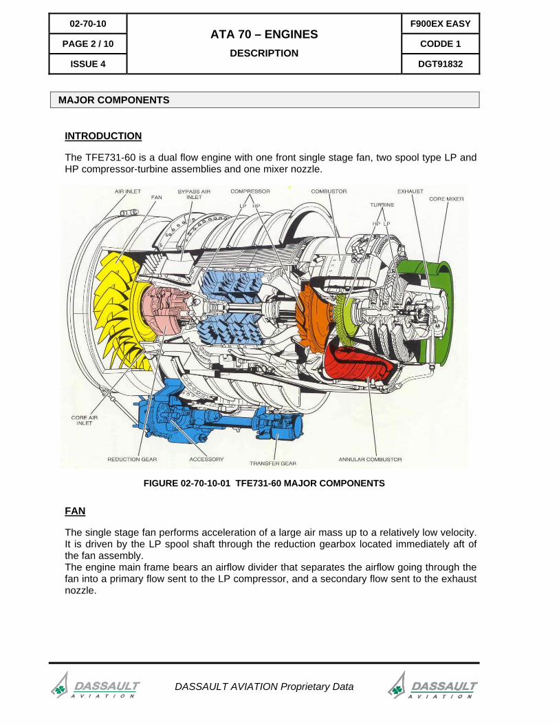
The TFE731-60 is a dual flow engine with one front single stage fan, two spool type LP and HP compressor-turbine assemblies and one mixer nozzle.
FIGURE 02-70-10-01 TFE731-60 MAJOR COMPONENTS
FAN
The single stage fan performs acceleration of a large air mass up to a relatively low velocity. It is driven by the LP spool shaft through the reduction gearbox located immediately aft of the fan assembly. The engine main frame bears an airflow divider that separates the airflow going through the fan into a primary flow sent to the LP compressor, and a secondary flow sent to the exhaust nozzle.

F900EX EASY 02-70-10
CODDE 1 PAGE 3 / 10
DGT91832
ATA 70 – ENGINES DESCRIPTION
ISSUE 4
DASSAULT AVIATION Proprietary Data
Fan LP compressor HP turbineHP compressor
Transfer gearboxAccessory gearbox
LP turbineSurge bleed valve
FIGURE 02-70-10-02 LP AND HP SPOOLS
LP SPOOL
The four stage LP compressor, driven by the LP turbine, directs the primary airflow through the HP compressor. The LP compressor includes a surge bleed valve, automatically operated by the Digital Electronic Engine Computer (DEEC), to prevent compressor from stalling or surging. The LP compressor also provides LP bleed air to the pneumatic system.
For more information, refer to CODDE1 / Chapter 02 / ATA 36. The three stage LP turbine, located downstream from the HP turbine, extracts the remaining energy of the exhaust gases to drive the four stage LP compressor and the fan through the reduction gear. The LP turbine, LP compressor and the fan form the LP spool section of the engine. The LP spool is designated N1 and rotates at approximately 21,000 rpm at 100% (fan rpm is around 10,000).

02-70-10 F900EX EASY
PAGE 4 / 10 CODDE 1
ISSUE 4
ATA 70 – ENGINES DESCRIPTION
DGT91832
DASSAULT AVIATION Proprietary Data
HP SPOOL
The single stage centrifugal HP compressor, driven by the HP turbine, provides high pressure airflow to the combustion chamber. It also supplies airflow to the pneumatic systems.
For more information, refer to CODDE1 / Chapter 02 / ATA 36.
The one-stage HP turbine, located downstream from the combustion chamber, extracts energy from the exhaust gases to drive the HP compressor and accessory gear. The HP compressor and turbine rotating assembly constitutes the HP spool of the turbofan engine. The HP spool is designated N2 and rotates at approximately 31,000 rpm at 100%.
COMBUSTION CHAMBER
The combustion chamber is divided into two parts: - in the first part, the combustion takes place. This part admits a limited quantity of
compressed air. - in the second part, the remaining airflow circulates and cools the combustion area.
The combustion chamber includes twelve duplex fuel spray nozzles and two high energy ignition plugs.
EXHAUST NOZZLE
Exhaust gases, exiting the LP turbine, are directed through the engine primary nozzle equipped with a mixer. The mixer forces high speed exhaust gases to mix with the fan peripheral secondary airflow. The gas mixture provides higher thrust and lower external noise level.
ACCESSORY GEARBOX
The accessory gearbox is driven by the HP spool through a transfer gearbox. It transmits the mechanical power necessary to:
- the fuel pump assembly and the Fuel Control Unit (FCU), - the oil pump, - the hydraulic pump, - the starter generator.
A dual-wound magnetic sensor is installed in the transfer gearbox to provide the avionics with the N2 rpm input signal.

F900EX EASY 02-70-10
CODDE 1 PAGE 5 / 10
DGT91832
ATA 70 – ENGINES DESCRIPTION
ISSUE 4
DASSAULT AVIATION Proprietary Data
OPERATING PRINCIPLE
Air inlet andbypass sections
Compressorsection
Combustionsection
LP turbineand exhaust
sections
Bypass duct
Fan housing
Singlestage fan bypass
sections
Reductiongear assembly
Core air inlet
Bypass air inlet
Accessory gear box Four stageLP compressor
Single stageHP compressor
Single stageHP turbine
Three stageLP turbine
ITT thermocouplesmounting area
N1 speed sensor
Exhaust nozzleand mixer
mounting area
FIGURE 02-70-10-03 TFE731-60 ENGINE MAJOR SECTIONS
The single-stage fan draws air in through the engine nacelle duct. The fan accelerates a large air mass up to a relatively low velocity into the full-length of the bypass duct and engine core. The pressure of the core airflow is increased in two steps by the LP compressor and the HP compressor before entering the combustion chamber. The air enters the combustion chamber where fuel is injected by the nozzles. When necessary (during engine start, stall or flameout detection) the mixture is ignited by the two high-energy igniter plugs. The mixture then expands through the turbine section. The HP turbine extracts energy to drive the HP compressor through the main rotor shaft on one hand and the accessory gearbox through bevel gears on the other hand. The LP turbine extracts energy to drive the LP compressor, the planetary gear and the single-stage fan through the LP rotor shaft. The LP turbine exhaust gas flow continues to accelerate through the exhaust mixer and mixes with the bypass airflow in the exhaust duct, which directs it into the atmosphere to provide the thrust. During engine start, the starter drives the HP spool (compressor and turbine). It stops operating when the engine reaches 45% N2 and is able to accelerate by itself. The generator is then connected to airplane electrical system (right main bus for No 2 engine and left main bus for No 1 and No 3 engines). The engine is self-sustaining when it reaches 70% N1 ground idle. Ignition is automatically shut down and bleed air is available for the pneumatic systems. If engine starter fails to stop when N2 reaches 45%, the STARTER ENG .. CAS message is displayed and an audio warning occurs.

02-70-10 F900EX EASY
PAGE 6 / 10 CODDE 1
ISSUE 4
ATA 70 – ENGINES DESCRIPTION
DGT91832
DASSAULT AVIATION Proprietary Data
ENGINE SYSTEM
The engine systems include the oil, fuel, and ignition systems described thereafter.
OIL SYSTEM
The oil system provides the HP and LP spools, the fan reduction gearbox and the accessory gearbox with lubrication and cooling. It mainly features:
- an electrical gauge, - an oil pump with a pressure regulator, - a clogging filter, - a chip detector, - two oil heat exchangers (one oil / air and one oil / fuel exchangers), - temperature and pressure probes.
The electrical gauge supplies oil quantity data to the avionics. The oil level can be checked by the CMC.
For details, refer to 02-70-15 pages 12 and 13.
The right engine is serviced through the tank filler while the left engine may be serviced through a crossover tube. All engine can be serviced through the tank filler or the crossover tube. In all cases the appropriate engine cowling must be open for servicing.
NOTE
Oil quantity should be checked within 10 min after engine shutdown, and serviced with the type and brand specified in the AFM (DGT84972).
The clogging filter is equipped with bypass line and a switch which transmits the filter clogging information. When the filter is clogged, prior to the bypass opening, the OIL FILTER .. CAS message appears within the CAS window. The chip detector plug attracts ferrous metal and detects important accumulation of particles. When ferrous metal particles accumulate on the chip detector, the related OIL CHIP .. CAS message appears within the CAS window. Engine oil pressure and temperature are sensed at the outlet of the oil / fuel heat exchanger. The data are displayed within the appropriate ENG synoptic and ENG - TRM - BRK window. Oil pressure is also sensed by pressure switches within the oil pressure line of each engine to provide warning of abnormally low pressure during operation. When the oil system pressure is below 50 psi, the OIL PRESS .. CAS message appears within the CAS window.

F900EX EASY 02-70-10
CODDE 1 PAGE 7 / 10
DGT91832
ATA 70 – ENGINES DESCRIPTION
ISSUE 4
DASSAULT AVIATION Proprietary Data
FUEL SYSTEM
The fuel system features a shut-off valve, the pressurizing system, the Fuel Control Unit and the distribution system.
Fuel shut-off valve
The fuel shut-off valve, located upstream from the pressurizing system, controls fuel supply. The valve automatically opens when the power lever position is set to IDLE position. In case of engine fire, the valve can also be controlled and shut off using the FUEL SHUT-OFF pushbutton, located on the fire warning panel.
For more information, refer to CODDE 1 / Chapter 02 / ATA 26.
Pressurizing system
The pressurizing system consists of a two stage pump (low and high pressure stages), feeding the FCU (Fuel Control Unit) with fuel at the required pressure and flow rate.
The fuel filter, installed between the two stages of the pump, is fitted with a by-pass valve. When the filter is clogged, the by-pass valve opens and activates the amber FUEL FILTER .. CLOGGED CAS message in the CAS message window.
The system also features an oil / fuel heat exchanger that warms the fuel and prevent the filter from being clogged by ice.
Fuel Control Unit
The Fuel Control Unit (FCU) includes a fuel-metering section, power-lever input, a shut-off valve, an outlet pressurizing valve and a mechanical speed governor.
In manual mode, the governor control is merely a flyweight-type governor operated from N2 rpm. As speed is selected with the power lever, the governor will react and regulate the proper amount of fuel to maintain the selected speed using the metering valve.
In automatic mode, the manual solenoid valve is energized. This allows two routes of regulated fuel pressure into the governor chamber and as a consequence resets the speeder spring of the flyweight governor. It then acts as an over speed governor. The DEEC controls its corresponding engine according to the throttle position.
Distribution system
The distribution system includes twelve duplex fuel spray nozzles, with primary and secondary ports, and one flow divider.
The flow divider directs metered fuel to the primary fuel manifold that feeds the 12 primary ports of the fuel nozzles. When fuel pressure increases, fuel is also directed to the secondary fuel manifold and the secondary port of the duplex fuel nozzles.

02-70-10 F900EX EASY
PAGE 8 / 10 CODDE 1
ISSUE 4
ATA 70 – ENGINES DESCRIPTION
DGT91832
DASSAULT AVIATION Proprietary Data
IGNITION SYSTEM
Each engine is equipped with an ignition system including one ignition exciter and two ignitor plugs. The ignition is initialized either manually by the pilot for normal or in-flight start-up, or automatically through stall warning circuits when high angle of attack is detected.
DEEC AUTO Ignition commanded by the DEEC when Power Lever Angle (PLA) moves from cut-off to idle
IGNITION
DEEC MAN Ignition commanded by the DEEC when Power Lever Angle (PLA) moves from cut-off to idle
Stall (high AOA) AUTO IGNITION
DEEC (N2 spool down)
IGNITION MANUALLY
Only with the IGN position on the engine selector
THRUST REVERSER
A thrust reverser system is installed on No 2 engine. It is designed, for ground operation only, to slow down the airplane after landing. The thrust reverser system consists of two thrust reverser doors tilting in the vertical plane under the action of two hydraulic actuators. It is powered by hydraulic No 2 system or by standby generation system. It also incorporates an accumulator allowing one extension and one retraction in case of hydraulic No 2 failure. Safety latch position (two per door), hydraulic pressure and time of operation are monitored to detect any malfunction. An auto-stow safety circuit commands hydraulic pressure to the retract side of the reverser actuators when any of the four latching hooks has been detected in an unsafe condition.
FIGURE 02-70-10-04 THRUST REVERSER IN NORMAL AND DEPLOYED POSITION

F900EX EASY 02-70-10
CODDE 1 PAGE 9 / 10
DGT91832
ATA 70 – ENGINES DESCRIPTION
ISSUE 4
DASSAULT AVIATION Proprietary Data
AUTOMATIC ENGINE CONTROL
The engines are electro-mechanically controlled by Digital Engine Electronic Computers (DEEC). The DEEC ensure fuel flow regulation as well as all checks necessary to keep the engines operational.
The DEEC performs:
- complete engine start control,
- opening of the surge bleed valve when necessary,
- engine N1 and N2 control through acceleration, deceleration and steady state operation,
- computation of N1 to achieve a flat-rated thrust of 5,000 lb.
It also protects the engine against damages by ensuring:
- start protection (hot start protection, with auto-start termination if ITT exceeds 994°C and hung start protection with auto-start termination if N1 = 0 at 30% N2),
- temperature limitation,
- overspeed protection,
- monitoring of N2 to avoid spool-down,
- automatic engine relight (on stall or flameout detection),
- ultimate overspeed protection in manual mode.
The DEEC also monitors its own functions and automatically reverts to manual mode in case of failure ( DEEC .. CAS message ).
NOTE
The automatic mode is the normal mode in all flight conditions. Automatic relight is stopped when engine falls below around 20% N1.
The DEEC can supply engine parameters (N1, N2, ITT) in the ENG synoptic instead of the normal analog inputs if a failure occurs. This reversion can be done by selected the DEEC boxes within the ENG synoptic display.
FIRE PROTECTION
On each engine, a temperature sensitive detector provides fire detection and monitors system integrity. Engine fire protection is provided by a total of four fire extinguisher cylinders, each cylinder supplying two of the three engines.
For more information, refer to CODDE1 / Chapter 02 / ATA 26.

02-70-10 F900EX EASY
PAGE 10 / 10 CODDE 1
ISSUE 4
ATA 70 – ENGINES DESCRIPTION
DGT91832
DASSAULT AVIATION Proprietary Data
INTENTIONALLY LEFT BLANK
F900EX EASY 02-70-15
CODDE 1 PAGE 1 / 14
DGT91832
ATA 70 – ENGINES CONTROL AND INDICATION
ISSUE 4
DASSAULT AVIATION Proprietary Data
CONTROL
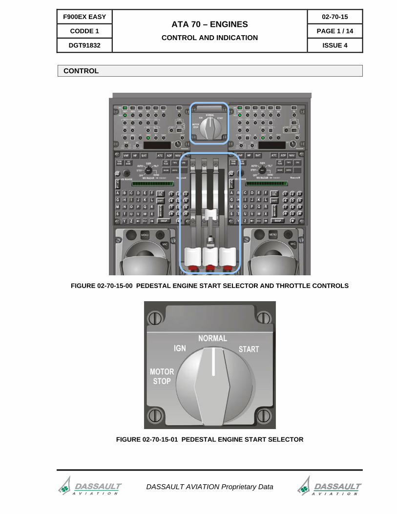
FIGURE 02-70-15-00 PEDESTAL ENGINE START SELECTOR AND THROTTLE CONTROLS
FIGURE 02-70-15-01 PEDESTAL ENGINE START SELECTOR
02-70-15 F900EX EASY
PAGE 2 / 14 CODDE 1
ISSUE 4
ATA 70 – ENGINES CONTROL AND INDICATION
DGT91832
DASSAULT AVIATION Proprietary Data
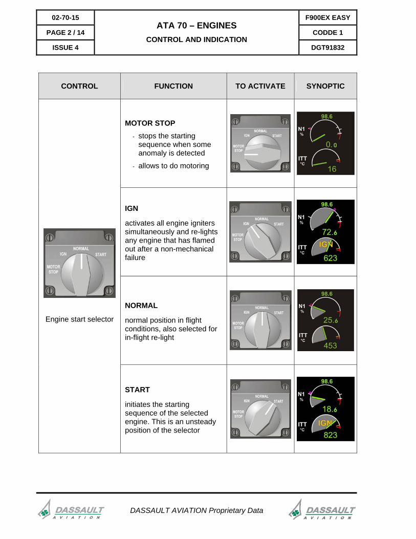
CONTROL FUNCTION TO ACTIVATE SYNOPTIC
MOTOR STOP - stops the starting
sequence when some anomaly is detected
- allows to do motoring
IGN
activates all engine igniters simultaneously and re-lights any engine that has flamed out after a non-mechanical failure
NORMAL
normal position in flight conditions, also selected for in-flight re-light
Engine start selector
START
initiates the starting sequence of the selected engine. This is an unsteady position of the selector

F900EX EASY 02-70-15
CODDE 1 PAGE 3 / 14
DGT91832
ATA 70 – ENGINES CONTROL AND INDICATION
ISSUE 4
DASSAULT AVIATION Proprietary Data
FIGURE 02-70-15-02 OVERHEAD PANEL DEEC ENGINE CONTROL
CONTROL FUNCTION TO ACTIVATE SYNOPTIC
AUTO mode: DEEC ensures complete control of the engine N1, N2, ITT limitation and over speed protection Engine auto START is only possible with the DEEC in AUTO mode
MAN mode: DEEC only provides N1 and N2 over speed protection. ITT limitation is not active.
OFF mode: overspeed protection is no longer provided
MAN START: manual start
HOLD TO MOTOR: engine ventilation
02-70-15 F900EX EASY
PAGE 4 / 14 CODDE 1
ISSUE 4
ATA 70 – ENGINES CONTROL AND INDICATION
DGT91832
DASSAULT AVIATION Proprietary Data
THROTTLE CONTROL UNIT
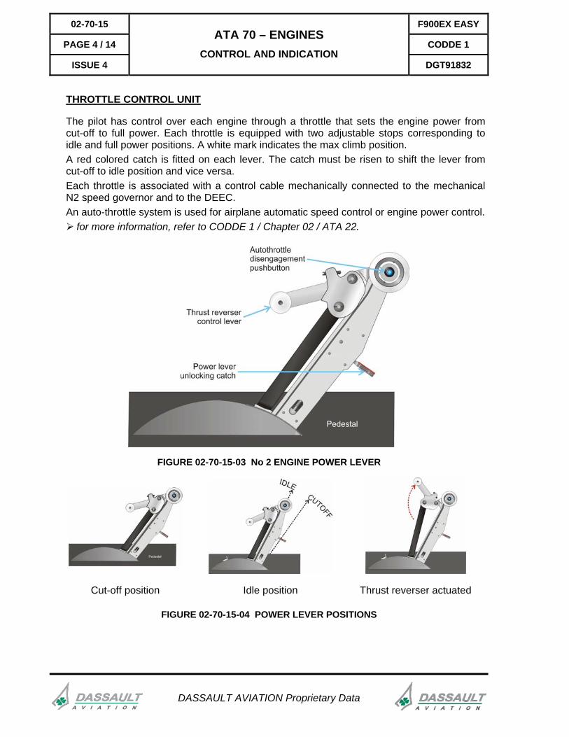
The pilot has control over each engine through a throttle that sets the engine power from cut-off to full power. Each throttle is equipped with two adjustable stops corresponding to idle and full power positions. A white mark indicates the max climb position. A red colored catch is fitted on each lever. The catch must be risen to shift the lever from cut-off to idle position and vice versa. Each throttle is associated with a control cable mechanically connected to the mechanical N2 speed governor and to the DEEC. An auto-throttle system is used for airplane automatic speed control or engine power control.
for more information, refer to CODDE 1 / Chapter 02 / ATA 22.
FIGURE 02-70-15-03 No 2 ENGINE POWER LEVER
Cut-off position Idle position Thrust reverser actuated
FIGURE 02-70-15-04 POWER LEVER POSITIONS

F900EX EASY 02-70-15
CODDE 1 PAGE 5 / 14
DGT91832
ATA 70 – ENGINES CONTROL AND INDICATION
ISSUE 4
DASSAULT AVIATION Proprietary Data
AUTO-THROTTLE ENGAGEMENT
FIGURE 02-70-15-05 AUTO THROTTLE GUIDANCE PANEL
Push on A/T pushbutton to engage auto-throttle. For more information, refer to CODDE 1 / Chapter 02 / ATA 22.
THRUST REVERSER
Switch over to thrust reverser mode is only possible when the throttle is in the IDLE position, after rising up the engine No 2 throttle reverser catch. As soon as the reverser catch is engaged in reverse-idle position, the engine throttle is locked into idle position. Until the thrust reverser is deployed, the engine No 2 power increases by pulling the reverser catch onto reverse-full power position (catch rear stop). Return to normal operation is performed by pushing back the reverser catch beyond the reverse-idle notch. Then the engine No 2 throttle lever becomes free to move normally.

02-70-15 F900EX EASY
PAGE 6 / 14 CODDE 1
ISSUE 4
ATA 70 – ENGINES CONTROL AND INDICATION
DGT91832
DASSAULT AVIATION Proprietary Data
SOFT KEYS CONTROLS
Selection of auto throttle mode, N1 / N2 synchronization and DEEC reversion modes is made through soft key controls located on the right side of the ENG synoptic.
A/T mode selection
Flex take-off (FLXTO) and Flex climb (FLXCLB) soft keys allow to manually set a take-off or a climb bug (soft keys are available on ground only). When one of the soft keys is depressed, the corresponding box is checked and a setting box is displayed next to the FLX TO or FLX CLB checked box. The CCD cursor is automatically displayed in the setting box and the pilot can set the required value using the rotary knob on the CCD base or the MKB numeric keypad. When the value is set, the flex take-off or climb bugs are displayed on the N1 scale (solid green triangular bug for FLXTO and green triangular bug for FLXCLB).
Depressing CRUISE soft key checks the corresponding box and limit the engine thrust to Max Cruise. This soft key is available in flight only.
A/T status ( if A/T is engaged or blank if not engaged) and mode annunciations (TO, FLX TO, CLB, FLX CLB, CRUISE or SPD) are displayed on the ENG synoptic.
The status, with TO, FLXTO, CLB, FLXCLB, CRUISE or SPD annunciations, are also displayed in the upper left corner of the PDU.
FIGURE 02-70-15-06 ENG SYNOPTIC
N1 or N2 synchronization
Depressing one of the two soft keys SYNC N1 and SYNC N2 selects either the N1 or N2 synchronization mode. The auto-throttle synchronizes the N1 or N2 of the three engines. No 2 engine is the master.

F900EX EASY 02-70-15
CODDE 1 PAGE 7 / 14
DGT91832
ATA 70 – ENGINES CONTROL AND INDICATION
ISSUE 4
DASSAULT AVIATION Proprietary Data
DEEC reversion
Depressing the DEEC REVERSION soft key checks the corresponding box and display engine parameters coming from the DEEC or ARINC instead of the normal analog data.
INDICATION
Engine parameters are displayed:
- in the ENG CAS window (primary parameters: N1, ITT and N2),
- in the ENG - TRM - BRK window (secondary parameters: fuel flow, oil pressure and temperature, LP and HP spool vibration levels),
- in the ENG synoptic (primary and secondary parameters).
ENGINE SYNOPTIC
The ENG synoptic allows the crew to display engine primary and secondary parameters, DEEC and A/T status and soft key controls.
FIGURE 02-70-15-07 ENG SYNOPTIC
The following information are displayed: - N1 %; - ITT, - N2 %, - Fuel Flow, - oil pressure and temperature, - N1 and N2 vibration levels, - APU N1 and T5, - A/T status and flex take-off / climb or cruise selection soft keys, - N1 and N2 SYNC modes and soft keys, - DEEC reversion and status.

02-70-15 F900EX EASY
PAGE 8 / 14 CODDE 1
ISSUE 4
ATA 70 – ENGINES CONTROL AND INDICATION
DGT91832
DASSAULT AVIATION Proprietary Data
N1 INDICATION
The PLA magenta bug indicates Power Lever Angle (throttle position). It shows the power required by the pilot. During acceleration or deceleration, the PLA bug and the needle indicating engine actual N1 may not be at the same location.
N1 indication during start sequence:
- PLA bug is at idle position
- engine is accelerating up to idle
In-flight N1 normal indication

F900EX EASY 02-70-15
CODDE 1 PAGE 9 / 14
DGT91832
ATA 70 – ENGINES CONTROL AND INDICATION
ISSUE 4
DASSAULT AVIATION Proprietary Data
- Data mismatch between MAU channels A and B
- Analog and numeric differential
N1 overspeed indication Invalid data
DEEC reversion selected Thrust reverser (engine No 2) in transit Thrust reverser deployed
FIGURE 02-70-15-08 N1 INDICATIONS SUMMARY

02-70-15 F900EX EASY
PAGE 10 / 14 CODDE 1
ISSUE 4
ATA 70 – ENGINES CONTROL AND INDICATION
DGT91832
DASSAULT AVIATION Proprietary Data
ITT INDICATION
Ignition activated Normal indication
Data mismatch between MAU channels A and B
Analog and numeric differential
Invalid data High temperature indication Over temperature indication
FIGURE 02-70-15-09 ITT INDICATION SUMMARY
F900EX EASY 02-70-15
CODDE 1 PAGE 11 / 14
DGT91832
ATA 70 – ENGINES CONTROL AND INDICATION
ISSUE 4
DASSAULT AVIATION Proprietary Data
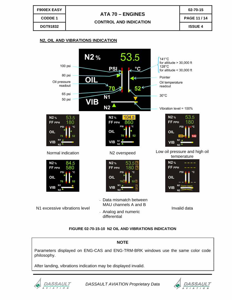
N2, OIL AND VIBRATIONS INDICATION
Normal indication N2 overspeed Low oil pressure and high oil temperature
N1 excessive vibrations level
- Data mismatch between MAU channels A and B
- Analog and numeric differential
Invalid data
FIGURE 02-70-15-10 N2 OIL AND VIBRATIONS INDICATION
NOTE
Parameters displayed on ENG-CAS and ENG-TRM-BRK windows use the same color code philosophy.
After landing, vibrations indication may be displayed invalid.

02-70-15 F900EX EASY
PAGE 12 / 14 CODDE 1
ISSUE 4
ATA 70 – ENGINES CONTROL AND INDICATION
DGT91832
DASSAULT AVIATION Proprietary Data
OIL LEVEL
Engine oil level is displayed on the Centralized Maintenance Computer (CMC) by selecting DAILY SERVICING.
FIGURE 02-70-15-11 ENGINE OIL LEVEL ON CMC
The engines oil level can be checked using the CMC Daily Servicing page or on the engine itself.

F900EX EASY 02-70-15
CODDE 1 PAGE 13 / 14
DGT91832
ATA 70 – ENGINES CONTROL AND INDICATION
ISSUE 4
DASSAULT AVIATION Proprietary Data
ENG-CAS WINDOW
The Primary Engine Instruments are displayed below the CAS Message Field. The Primary Engine Instruments consist of:
- Low Pressure compressor rotation speed (N1) analog gauge and digital readout, - N1 active limit (at take off), - Inter Turbine Temperature (ITT) analog gauge and digital readout, - High Pressure compressor rotation speed (N2) digital readout for each engine.
FIGURE 02-70-15-12 ENG-CAS PERMANENT WINDOW

02-70-15 F900EX EASY
PAGE 14 / 14 CODDE 1
ISSUE 4
ATA 70 – ENGINES CONTROL AND INDICATION
DGT91832
DASSAULT AVIATION Proprietary Data
ENG-TRM-BRK WINDOW
The engine-trim-brake window displays secondary engine parameters (fuel, oil and vibration data). The ENG-TRM-BRK window can be displayed to the pilot in each PDU. There is no graphic interface available in this window. The AFM and checklist require this window to be displayed on the Pilot Flying PDU for take-off and landing.
FIGURE 02-70-15-13 ENG-TRM-BRK WINDOW
The ENG-TRM-BRK window provides the following engine information: - fuel flow digital readout, - oil pressure and temperature digital readouts, - N1 and N2 vibrations scales.
The ENG-TRM-BRK window automatically pops-up in case an engine parameter exceeds limitations.

F900EX EASY 02-70-20
CODDE 1 PAGE 1 / 2
DGT91832
ATA 70 – ENGINES SYSTEM PROTECTION
ISSUE 4
DASSAULT AVIATION Proprietary Data
CIRCUIT BREAKERS
FIGURE 02-70-20-00 ENGINES CIRCUIT BREAKERS PANEL
02-70-20 F900EX EASY
PAGE 2 / 2 CODDE 1
ISSUE 4
ATA 70 – ENGINES SYSTEM PROTECTION
DGT91832
DASSAULT AVIATION Proprietary Data
INTENTIONALLY LEFT BLANK

F900EX EASY 02-70-25
CODDE 1 PAGE 1 / 2
DGT91832
ATA 70 – ENGINES NORMAL OPERATION
ISSUE 4
DASSAULT AVIATION Proprietary Data
ENGINE AUTO-STARTING (DEEC AUTO MODE)
Automatic engine start is achieved through the pedestal engine start selector located in front of the throttles. The engine power lever must be moved from the CUT-OFF to the IDLE position before the engine start selector is turned to the START (spring loaded) position.
The system automatically turns on the corresponding fuel booster pump and manages the generators to provide the required electrical power on the starting bus. The DEEC monitors the correct starting sequence and control ignition.
NOTE
The engines start sequence is No 2, 3 and 1.
In case of an anomaly, the crew can stop the starting sequence at any time by selecting the MOTOR STOP position.
In-flight, re-light of any engine can be achieved by selecting the IGN position, which activates all engine igniters simultaneously. Ignition can also be automatically commanded by the stall protection system and by the DEEC upon detection of rapid engine deceleration.
For more information, refer to CODDE 2.
In case of flameout or failed start, the power lever must be pulled back to the CUT-OFF position before restart.
ENGINE SHUTDOWN
To shut down engine, the engine power lever must be moved from the IDLE to the CUT-OFF position by raising the red-colored catch and pulling the lever back. The engine start selector can then be turned to the MOTOR STOP position.
The system automatically turns off the corresponding fuel booster pump and the DEEC monitors the stopping sequence.

02-70-25 F900EX EASY
PAGE 2 / 2 CODDE 1
ISSUE 4
ATA 70 – ENGINES NORMAL OPERATION
DGT91832
DASSAULT AVIATION Proprietary Data
INTENTIONALLY LEFT BLANK

F900EX EASY 02-70-30
CODDE 1 PAGE 1 / 2
DGT91832
ATA 70 – ENGINES ABNORMAL OPERATION
ISSUE 4
DASSAULT AVIATION Proprietary Data
ENGINE MANUAL START AND MOTORING
In case of failure of the DEEC AUTO mode, engine starting is achieved through the manual start controls on the overhead panel. Pressing the MAN START round pushbutton starts rotation of the N2 compressor. Pilot must then manually move the engine power lever to the idle position at N1 indication to initiate the starting sequence.
NOTE
In case of flameout or failed start, the power lever must be cycled to the cut-off position before restart.
For abnormal and emergency procedures: refer to CODDE 2 / Chapter 03.
CAS MESSAGES
CAS MESSAGE DEFINITION
ALL ENGINES OUT All engines not running in-flight
ENG 2 FAIL On ground and take-off, failure of engine 2
ENG 2 DUCT Non locking of door of engine 2 air duct
FIRE ENG .. Fire detected on engine (1/2/3)
OIL PRESS .. Oil pressure of one engine (1/2/3) is below 50 psi and the engine is running
THRUST REVERSER Anomaly in deployment or retraction sequence
CHECK OIL .. Oil pressure for engine (1/2/3) is out of green range when engine running
DEEC .. Failure of engine computer (1/2/3) is not in AUTO mode
DEEC .. FAULT 1 Engine computer (1/2/3) failure class 1
DEEC .. FAULT 2 On ground, engine computer (1/2/3) failure class 2
ENG .. OUT In-flight, engine (1/2/3) not running
ENG .. FIRE DETECT FAIL Failure of engine (1/2/3) fire detector
ENG .. VIBRATION Vibration above 100% for N1 or N2 of an engine (1/2/3)
FUEL FILTER .. CLOGGED Fuel filter concerned bypassed. See note below.
FUEL HEATER.. LO On ground, fuel temperature (1/2/3) lower than 10°C

02-70-30 F900EX EASY
PAGE 2 / 2 CODDE 1
ISSUE 4
ATA 70 – ENGINES ABNORMAL OPERATION
DGT91832
DASSAULT AVIATION Proprietary Data
CAS MESSAGE DEFINITION
STARTER ENG .. Engine (1/2/3) is ON and starter still active
DEEC .. FAULT 2 In-flight, engine computer (1/2/3) failure class 2
DEEC .. OK DEEC (1/2/3) failure is cleared It is possible to reselect AUTO mode
ECTM CHK ENG .. On park, engine (1/2/3) failure word was recorded in the Engine Condition Trend Monitoring Computer
ECTM FULL .. On park, Engine Condition Trend Monitoring Computer (1/2/3) memory is full
FUEL FILTER .. CLOGGED In flight, indication that fuel filter (1/2/3) is (are) clogged and bypassed
FUEL HEATER .. HI Indication of abnormal fuel heater (1/2/3) operation (temperature above 135°C)
FUEL HEATER .. LO In flight, indication of abnormal fuel heater (1/2/3) operation (temperature below 10°C)
IGN A .. FAIL Ignition failure circuit A (engine 1/2/3)
IGN B .. FAIL Ignition failure circuit B (engine 1/2/3)
IGN SYS .. FAIL Complete ignition failure (engine 1/2/3)
OIL .. FAIL On ground, indication of oil system failure (1/2/3) (open circuit)
OIL CHIP .. On ground, oil chip detected (1/2/3)
OIL CHIP .. FAIL On ground, oil chip detector concerned (1/2/3) failed (open circuit)
OIL FILTER .. On ground, oil filter concerned (1/2/3) bypassed. See note below.
NOTE
If FUEL FILTER .. CLOGGED or OIL FILTER .. CAS messages are displayed they will not visible during the daily servicing. They will only appear again at next start up, which can delay the corresponding flight. Before complete shut-down, record these CAS messages (if visible) and report to the maintenance staff.