f:: :: r,,,. '-i- - i.--i rtr 142-03
TRANSCRIPT

i I
m
, I_.i
ii|
!
!W
RTR 142-03
- -T-/ "SRB THERMAL_IRONMENTS
FINAL REPORT
June 1989
Prepared by:
W. K. Craln
E. C. Knox
C. L. Frost
C. D. Enge]
REMTECH, Inc.
-L T-_ -
i ! - For:m _d_
= i ....
i m_, - _. _Ngtional Space and Aeronautics Administrationm • _ - _
| __l ...........: - ........ -George C. Marshall Space Flight Center
i i _Marshall Space FlighgCenter_ AL 35812
• i

w
F::__:: r,,,._ '-I- _- _ i.--i RTR 142-03
FOREWORD
This final report documents the SRB thermal environment work performed
under the SRB REENTRY THERMAL ENVIRONMENT contract (NAS8-36476).
The work was performed for the Induced Environments Branch (ED-33) for the
George C. Marshall Space Flight Center (MSFC).
i

DF:_ _: M'T _:C _-4 RTR 142-03
Contents
1 INTRODUCTION
2 SRB REENTRY THERMAL ENVIRONMENTS
3 MISSION 51L SRB FAILURE ANALYSIS
4 SRM JOINT REDESIGN ANALYSIS
1
3
24
38
ii

I=_ _" M"I- _" C I---! RTR 142-03
List of Figures
2.1 Internal Aft Skirt Body Point Distribution ..............
2.2 Nozzle Flame Radiation Model ....................
2.3 Combustion Chamber Dome Heating .................
2.4 Internal Aft Skirt Heating .......................
2.5 Field Joint Stiffeners..........................
2.6 Typical Field Joint StiffenerTotal Environment ...........
3.1 Leak Plume Impingement "Footprint" on E.T. Sidewall ......
3.2 R-SRB Leak Plume Impingement Heating on E.T. Sidewall ....
3.3 SRB Aft Separation Motor Design Point Locations .........
3.4 Final EXITS Result (Liquid Layer 10 Particle Diameters Thick)
4.1 NASA/MSFC 70-lb. Motor Test Apparatus .............
4.2 Comparison of Predicted and Measured Subscale Test Results . .
4.3 Comparison of Predicted and Measured Full-scale Test Results
6
16
17
18
21
22
27
28
31
34
40
41
48
Qo_
111
F_'M-r-_'C I---I RTR 142-03
w
w
m
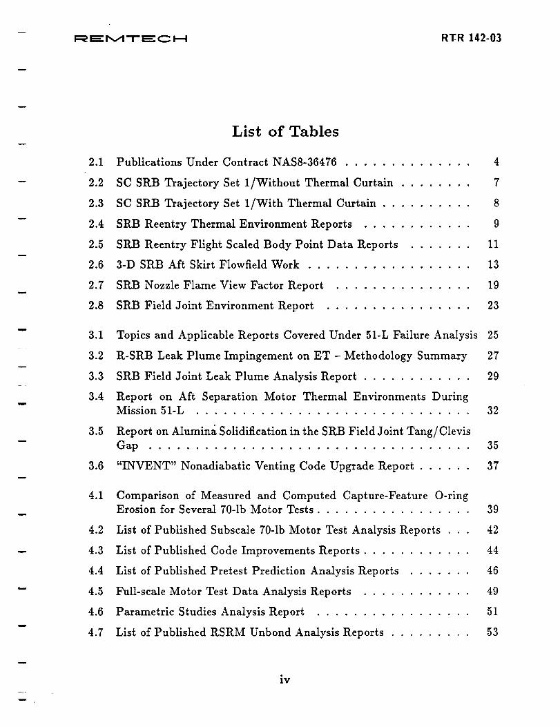
List of Tables
2.1 Publications Under Contract NAS8-36476 .............. 4
2.2 SC SRB Trajectory Set 1/Without Thermal Curtain ........ 7
2.3 SC SRB Trajectory Set 1/With Thermal Curtain .......... 8
2.4 StLB Reentry Thermal Environment Reports ............ 9
2.5 StLB Reentry Flight Scaled Body Point Data Reports ....... 11
2.6 3-D SRB Aft Skirt Flowfield Work .................. 13
2.7 SRB Nozzle Flame View Factor Report ............... 19
2.8 SRB Field Joint Environment Report ................ 23
3.1 Topics and Applicable Reports Covered Under 51-L Failure Analysis 25
3.2 R-SRB Leak Plume Impingement on ET - Methodology Summary 27
3.3 SRB Field Joint Leak Plume Analysis Report ............ 29
3.4 Report on Aft Separation Motor Thermal Environments During
Mission 51-L .............................. 32
3.5 Report on Alumina Solidification in the SRB Field Joint Tang/Clevis
Gap ................................... 35
3.6 "INVENT" Nonadiabatic Venting Code Upgrade Report ...... 37
4.1 Comparison of Measured and Computed Capture-Feature O-ring
Erosion for Several 70-1b Motor Tests ................. 39
4.2 List of Published Subscale 70-1b Motor Test Analysis Reports . . 42
4.3 List of Published Code Improvements Reports ............ 44
4.4 List of Published Pretest Prediction Analysis Reports ....... 46
4.5 Full-scale Motor Test Data Analysis Reports ............ 49
4.6 Parametric Studies Analysis Report ................. 51
4.7 List of Published RSRM Unbond Analysis Reports ......... 53
iv
w

r
RTR 142-03
4.8 SRB Aft Skirt Weld Failure Analysis Report ............ 55
m
m
L _
w
w
v

ORIGINAL PAGE iSOF POOR QUAL!TY
Section 1
INTRODUCTION
The objective of this contract was to utilize and expand the Solid Rocket
Booster orbital flight test data base for better predictions of future flight envi-
ronments. There were five tasks associated with this effort:
m
L
w
o
2_
.
.
.
analyze the internal aft skirt wind tunnel data and incorporate it into a data
base for generating design and preflight reentry thermal environments,
generate reentry design thermal environments for the SRB steel case with
the nozzle extension off,
generate reentry design thermal environments for the SRB Filament Wound
Case with the nozzle extension off,
develop an engineering tool to analyze the 3-D flowfield around the SRB aft
skirt during reentry for the purpose of obtaining the frequency and severity
of the belching gas intrusion internal to the aft skirt, and
perform SRM transient joint flow analysis for subscale and full scale motor
firing as well as determine the effects of debonds of the insulation on the fill
time and heating within the field joint insulation.
In addition, this work was extended to provide support for the 51L Shuttle
SRB failure analysis.
All work items under this contract have been addressed. The purpose of this
report is to document this work in summary fashion. During the course of the
contract, significant results and progress were documented in monthly progress
reports (RPR 142-01 through 46), and an assortment of memos, technical notes,
technical reports, and design environment documents were prepared and released
to the cognizant NASA offices. Details of the individual reports will not be revis-
ited, but a summary of work performed will be presented. This work will fall under
three main categories and will contain a brief description of each item, significant
findings, and a list of all applicable document numbers. These categories are:
1. SRB reentry thermal environments,
i
F:_ _" M-r" ¢="C l--! RTR 142-03
2. Mission 51L StLB failure analysis support, and
3. SRM field joint redesign.
ORIGINAL PAGE iS
OF. POOR QUALITY
2
F::_'r,,_-r'_"_ i..-i RTR 142-03
Section 2
SRB REENTRY THERMAL ENVIRONMENTS
The SRB reentry thermal environment work consists of SRB flight reentry
and wind tunnel heating data analysis, incorporation of that data into a base for
predicting flight environments, and design reentry environments for the Filament
Wound Case and steel case both with the nozzle extension off. In addition, nozzle
flame view factors were calculated to support nozzle flame environment calcula-
tions_ and field joint stiffener environments at the forward and mid locations were
calculated from liftoi_to splashdown. Topics and reports applicable to the enclosed
work are listed in Table 2.1. A brief summary of each follows.
w
3

I=_ _" M-r- _: C P--I RTR 142-03
Table 2.1: Publications Under Contract NAS8-36476
RTR 142-01
RTR 142-02
RTN 142-01
RTN 142-02
Technical Reports
Engel, C. D., and Frost, C. L., "FWC SRB Reentry Ther-
mal Environment," January 1986.
Engel, C. D., and Frost, C. L., "Steel Case SRB Nozzle
Extension Off-Reentry Thermal Environment," January
1986.
Technical Notes
Engel, Carl D. and Frost, Cynthia L., "FWC SRB Flight
Scaled Body Point Data Base," October 1985.
Engel, Carl D. and Frost, Cynthia L., "Steel Case SRB
Without Nozzle Extension Flight Scaled Body Point Data
Base," November 1985.
RTN 142-03
RTN 142-07
Engel, Carl D., and Reardon, John E., "SRB Nozzle Flame
View Factors," December 1985.
Engel, C. D., Bancroft, S., "Field Joint Stiffener Environ-
ments at FWD and Mid SRB Location," June 1986.
Additional Topics
3D CFD Nozzle Flame/Aft Skirt Modeling
SRB Reentry Wind Tunnel Data Base
4
m
TOPIC: SRB Reentry Thermal Environments
These documents contain the statistical reentry design thermal environments
for the filament wound and Steel Case Space Shuttle Solid Rocket Booster (SRB).
Included are the necessary instructions to use the environments. The reentry envi-
ronments include aerodynamic heating, aerodynamic cooling, and radiation from
burning gas discharge from within the solid rocket motor (SRM). Calculated envi-
ronments include nozzle flame heating and are referenced to Tw = 600°R. These
data are intended to be used in conjunction with the ascent and separation ther-
mal environments for the determination of the thermal protection system (TPS)
requirements for reuse of the SP_ when the nozzle extension is severed at apogee.
These environments are based primarily on the flight data base generated from
the design, development, test and evaluation (DDT&E) Shuttle flights and the
operational trajectories, along with a statistical methodology.
The reentry thermal environments have been generated using the latest aerody-
namics (J. Hengel, ED32-85-33), statistical trajectory set (G. Watts, ED13-27-85)
and configuration (ICD-2-00001 Revision G and F IRN's). Separation of the nozzle
extension is assumed to occur near apogee.
The SRB is divided into zones and each area of interest assigned a body point
within the zone. Heating rate and integrated heat load were then calculated for
each body point. The trajectory set considered 200 trajectories. The aerodynamic
heating characteristics of this set were analyzed to predict the range of heating that
will occur and the likelihood of a certain heating load being obtained. For every
body point on the SRB, four thermal environments are documented, corresponding
to the 0%, 50%, 95%, and 100% heating statistics based on 200 Monte Carlo
trajectories.
Heating load summary tables for each of the body points are presented as
well as the parachute trajectory. An example of this is shown in Fig. 2.1 and
Tables 2.2 - 2.3 for zone 9. Figure 2.1 gives the body point distribution and
Tables 2.2 and 2.3 present the integrated heat load summary for the steel case
SRB. Documents published under this topic are summarized in Table 2.4.
5

!
i=_ _- r,,,,_-r- _- c _--I RTR 142-03
COMBUSTION
DOME
w
i
E,
i
Figure 2.1: Internal Aft Skirt Body Point Distribution
6

Table 2.2: StatisticalThermal Environment - SC SRB Trajectory Set 1/Without
Thermal Curtain/Tw - 600
i
Zone 9
Zone 9
Zone 9
Zone 9
Zone 9
Zone 9
Zone 9
Zone 9
Zone 9
Zone 9
Zone 9
Zone 9
Zone 9
Zone 9
Zone 9
Zone 9
Zone 9
Zone 9
Zone 9
Zone 9
Zone 9
Zone 9
Zone 9
Zone 9
Zone 9
Zone 9
Zone 9
Zone 9
Zone 9
Zone 9
PT 102
PT 103
PT 104
PT 106
PT 107
PT 108
PT 110
PT 111
PT 112
PT 113
PT 122
PT 123
PT 124
PT 126
PT 127
PT 128
PT 130
PT 131
PT 132
PT 133
PT 142
PT 143
PT 144
PT 146
PT 147
PT 148
PT 150
PT 151
PT 152
PT 153
Theta = .00
Theta = .00
Theta = .00
Theta - .00
Theta = .00
Theta = .00
Theta = .00
Theta -- .00
Theta = .00
Theta = .00
Theta = 120.00
Theta = 120.00
Theta = 120.00
Theta = 120.00
Theta = 120.00
Theta = 120.00
Theta = 120.00
Theta = 120.00
Theta = 120.00
Theta -- 120.00
Theta = 240.00
Theta = 240.00
Theta = 240.00
Theta = 240.00
Theta = 240.00
Theta = 240.00
Theta = 240.00
Theta = 240.00
Theta = 240.00
Theta = 240.00
0% 50% 95% 100%
Load = 173.8 198.5 219.5 235.2
Load = 173.8 198.5 219.5 235.2
Load = 157.5 192.7 219.3 237.6
Load = 168.0 207.5 242.0 273.8
Load = 119.9 143.3 162.3 178.8
Load = 137.5 163.1 184.8 197.5
Load = 119.3 149.4 173.4 191.4
Load = 115.7 140.5 160.8 175.0
Load = 151.7 183.4 208.4 220.6
Load = 129.1 150.7 171.1 187.0
Load = 167.1 195.2 214.8 232.7
Load = 167.1 195.2 214.8 232.7
Load = 142.7 173.7 204.1 229.4
Load = 142.1 178.5 224.6 268.8
Load = 112.1 137.1 156.0 176.8
Load = 125.2 154.1 175.9 204.7
Load = 108.5 131.9 158.3 191.0
Load = 106.9 133.6 152.8 177.2
Load = 135.2 172.5 203.2 229.5
Load = 119.1 143.3 164.9 182.0
Load = 171.4 199.9 221.7 233.0
Load = 171.4 199.9 221.7 233.0
Load = 145.9 186.6 212.6 223.8
Load = 157.9 203.7 240.2 260.9
Load = 116.8 143.1 163.3 174.5
Load -" 130.4 160.4 183.9 197.7
Load = 115.4 146.5 170.7 184.4
Load = 107.1 136.3 157.3 171.5
Load = 145.3 182.3 211.1 226.3
Load = 118.8 147.0 170.9 181.2
7

w
I=_ ".'.'.'.'.'.'.'.'.="rvl "r- mE:c J--i RTR 142-03
Table 2.3: Statistical Thermal Environment - SC SI_B Trajectory Set 1/_With
Thermal Curtain/Tw = 600
Zone 9
Zone 9
Zone 9
Zone 9
Zone 9
Zone 9
Zone 9
Zone 9
Zone 9
Zone 9
Zone 9
Zone 9
Zone 9
Zone 9
Zone 9
Zone 9
Zone 9
Zone 9
Zone 9
Zone 9
Zone 9
Zone 9
Zone 9
Zone 9
Zone 9
Zone 9
Zone 9
Zone 9
Zone 9
Zone 9
PT 102
PT 103
PT 104
PT 106
PT 107
PT 108
PT 110
PT 111
PT 112
PT 113
PT 122
PT 123
PT 124
PT 126
PT 127
PT 128
PT 130
PT 131
PT 132
PT 133
PT 142
PT 143
PT 144
PT 146
PT 147
PT 148
PT 150
PT 151
PT 152
PT 153
Theta = .00
Theta = .00
Theta = .00
Theta = .00
Theta = .00
Theta = .00
Theta = .00
Theta = .00
Theta = .00
Theta = .00
Theta = 120.00
Theta = 120.00
Theta = 120.00
Theta = 120.00
Theta = 120.00
Theta = 120.00
Theta = 120.00
Theta = 120.00
Theta = 120.00
Theta = 120.00
Theta = 240.00
Theta = 240.00
Theta = 240.00
Theta = 240.00
Theta = 240.00
Theta = 240.00
Theta = 240.00
Theta = 240.00
Theta = 240.00
Theta = 240.00
0% 5O% 95% 100%
Load = 133.1 155.1 171.6 188.0
Load = 133.1 155.1 171.6 188.0
Load = 129.1 155.6 178.9 198.8
Load = 139.8 172.5 205.1 237.2
Load = 98.2 118.5 137.6 153.8
Load = 110.7 134.9 156.1 167.6
Load = 98.8 123.1 146.8 166.3
Load = 94.2 118.8 135.4 151.7
Load = 124.7 150.4 176.9 187.6
Load = 103.3 124.4 141.2 155.8
Load = 129.4 157.0 172.0 185.7
Load = 129.4 157.0 172.0 185.7
Load = 113.4 137.2 163.2 194.9
Load = 114.5 144.4 189.3 230.9
Load = 92.3 115.4 131.9 150.0
Load = 102.2 128.2 148.8 174.2
Load = 88.7 107.1 134.4 166.2
Load = 87.7 112.0 131.2 154.4
Load = 109.2 142.8 174.0 198.6
Load = 97.1 114.6 138.2 155.1
Load = 133.3 158.5 177.3 187.2
Load = 133.3 158.5 177.3 187.2
Load = 119.5 154.5 175.2 182.9
Load = 138.2 169.6 204.6 224.9
Load = 96.5 119.9 135.9 149.1
Load = 107.1 133.2 153.4 164.4
Load = 93.8 122.8 145.3 160.0
Load = 88.2 115.9 133.8 144.7
Load = t20.2 153.5 180.7 191.3
Load = 96.5 122.6 145.0 150.4
8
w
i=_ _" P,,.,,1-1- E:: C i--I RTR 142-03
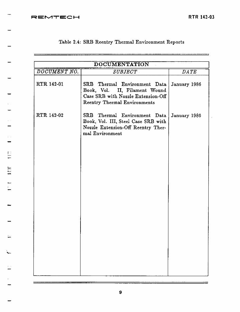
Table 2.4: SRB Reentry Thermal Environment Reports
w
u
w
w
L
%.--
D 0 CTflVIENTATION
D 0 C UMENT NO. S UBIECT DA TE
RTR 142-01
RTR 142-02
SRB Thermal Environment Data
Book, Vol. II, Filament Wound
Case SRB with Nozzle Extension-Off
Reentry Thermal Environments
SRB Thermal Environment Data
Book, Vol. III, Steel Case SP_B with
Nozzle Extension-Oil" Reentry Ther-
mal Environment
January 1986
January 1986
m

R, !_ M T I=="C H RTR 142-03Errata
TOPIC: SRB Reentry Flight Scaled Body Point Data Base
An interference factor data base for each of the gage locations on the SRB
FWC and Steel Case was generated by reducing the flight heating data. The flight
data was then used to replace and/or to scale the wind tunnel data. This scaling
was done by the use of a multiplication factor. The scaling algorithm is defined
in this report. This algorithm is defined for each of the body points. Equivalent
body point numbers are given for some body points. An interference factor matrix
is not generated for body points which are defined by an equivalent point.
The transformation relations (Appendix A of RTN 142-01) are read into the
SRBttIttU4 code which performs the indicated function. SRBHIHU4 uses both
the flight gage data base and the wind tunnel data base as input. A listing of
the transformation code is given in Appendix B of RTN 142-01, and 142-02. The
output from SRBHTRU4 is the flight data scaled interference factor matrix for each
non-equivalenced body point. These factors were put on tape for use in generating
the final environments. Reports documenting this work are listed in Table 2.5.
10

Table 2.5: SRB Reentry Flight Scaled Body Point Data Reports
DOCUMENTATION
DOCUMENT NO. SUBJECT DA TE
RTN 142-01
RTN 142-02
FWC SRB Flight Scaled Body PointData Base
Steel Case SRB Without Nozzle Ex-
tension Flight Scaled Body PointData Base
Oct. 1985
Nov. 1985
w
11
_q
Sl
st
I_' I_: M T E: C FI RTR 142-03Errata
TOPIC: CFD Nozzle Flame/Aft Skirt Modeling
The purpose of this work was to develop a 3D CFD flowfield code to calculate
the frequency and severity of the nozzle flame belching gas intrusion internal to the
aft skirt. Angles of attack from 90 to 180 degrees were to be considered for both
nozzle extension off and on configurations. Moreover, both supersonic, M=3.75,
and subsonic, M--0.5, conditions were to be investigated. The conduct of this
work was implemented through a subcontract with American Computing Inc. ofAuburn, Alabama.
Work was initiated on this subcontract work on August 2, 1985, and was pro-
gressing smoothly and according to schedule through January 1986. Due to the
51L accident, this work was halted by a stop work order issued on February 14,
1986. The subcontract status at time of the stop work order is summarized inTable 2.6.
Recent advances in CFD code capabilities would make the goal of calculating
nozzle flame entrainment more tractable. Thus, the technical risk of achieving
the program goal is significantly reduced within the past four years. Recent flight
data have shown that the nozzle flame heating can be quite significant. A renewed
attempt at defining this heating mechanism is recommended for both the currentStLB and the new ASRM.
a-]12

F_e_::r,,Jl-r-E:C I--I RT-R ]42-03
Table 2.6: 3-D SI_ Aft Skirt Flowfield Work
m
w
Task 1.1 Planning
Task 1.2 Basic Hydrodynamic Subroutine
a. Coefficient Subroutines
b. Source Subroutines
c. Linear Equation Solver
d. Outflow Boundary Condition
Task
a.
b.
C°
d.
e,
1.3 Models
Scalar Coefficient Subroutines
k-equation
Epsilon Equation
Concentration Equation
Wall Functions for all six equations
Task 1.4 Geometry Input (Axisymmetric)
a. Data Format
b. Porosity Subroutines
Task
a.
b.
C.
d.
1.5 Skew Differencing
2-D Polar Coordinates, Scalar
2-D Polar Coordinates, Velocities
3-D Cylindrical Coordinates, Scalar
3-D Cylindrical Coordinates, Velocities
Task 1.6 Verification Test Cases
a. Flow Over Cylinder
b. Flow Around Disk
Total
Completed
100
i00
I00
I00
75
100
i00
I00
100
90
100
100
75
75
50
0
50
0
13

w
F=__" r',_ "T" _: _ I---I RTR 142-03
m
n
Table 2.6: 3-D StLB Aft Skirt Flowfield Work (Concluded)
Task 1.7 Graphical Output (at Auburn)
a. Vector Plots
b. Color Temperature Plots
Task 2.1 Input SRB Data
a. Geometry
b. Exhaust Gas Properties
Task 2.2 Move Operation to Cray Computer
Total
Completed
(%)
50
0
0
0
0
Task 2.3 Testing, Debugging, Solving Convergence Problems 18
Total Contract 39
The code at this point was basically written, but required debugging.
containing the program "as is" was delivered to MSFC on March 18, 1986.
A disk
14
Jf
I::_ EE M-T- E C I--I R'FR 142-03
n
m
TOPIC: SI_B Nozzle Flame View Factors
In order to estimate the radiative heating external to the aft skirt due to the
nozzle flame during reentry, radiative heating rates were calculated for a hypo-
thetical flame. Relative view factors can then be determined from these radiative
heating values. The heat loads for body points in Zones 8 and 9 can then be
obtained by multiplying the relative view factor for a point by the reference load
for that zone.
The nozzle flame was modeled as a slab with an emissive power of 100 BTU/ft-
sec. The slab location and size is shown in Fig. 2.2 for the nozzle extension-on
configuration. The slab was translated to XB = 1930.64 for the nozzle extension-off
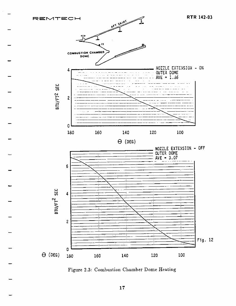
calculations. Radiative heating rates are plotted as a function of circumferential
angle from 90 to 180 degrees for 15 aft skirt regions. (An example of this is
presented in Figs. 2.3 and 2.4.) The average values given on the figures are the
average of all nodes shown for the component over the 90 to 180 degree interval.
Each figure contains nozzle extension-on and -off data for a specific component.
View factor ratios may be obtained by ratioing the heating rates to those at
another location where flight data measurements were obtained. The view factor
can then be multiplied by the reference gage heating load to give the heating load
at that location. To obtain the reference heating loads, the heating rates for the
interval from 360.2 to 380.0 seconds were also used from 340.2 to 360.0 seconds
for STS-3 and STS-5. The time, heating rate, and heating load for each of the
reference gages is also presented. The report documenting this work is listed in
Table 2.7.
15

F:_Er',,._-'I-EC H RTR ].42-03
CONCEPTUALFLAME
SLABFLAME
t,1930.64 X B= 2000.2
CONCEPTUALFLAME
e 8=180
08 =90
Figure 2.2: Nozzle Flame Radiation Model
16
COMBUSTION CHAMB_
--o0_--_
_J
h-L6
h-
6) CDEG)
4 NOZZLE EXTENSION - ON................................... OUTER DOME
2
0
4
180 160 140 120 100
(,.}l,i
¢%/I-'-
I,-'-r.m,
e (DEG)
NOZZLE EXTENSION - OFF
OUTER DOME
AVE : 3.07
! r ; • i J •
0
180 160 140 120 I00
RTR 142-03
Fig. 12
Figure 2.3: Combustion Chamber Dome Heating
17

I=_ I=="M -I- _ C l--i '"*" RTR 142-0311= •
!
z,:Ise4.1s _-) AFT SKIRT
m
_"MI--i,
I---
0
180
30
20
10
0
180
4c_2 -
160 140 120 I00
E) (DEG)
160 140 120
.... NOZZLE EXTENSION - ON........... AFT SKIN - INNER
: 1.16
100
NOZZLE EXTENSION - OFF
AFT SKIN - INNER
AVE : 9.35
Fig. 5
e (DEG)
Figure 2.4: Internal Aft Skirt Heating
18

w
F_'P,,A'-I-='C J--I R'FR 142-03
Table 2.7: SRB Nozzle Flame View Factor Report
m
DOCUMENTATION
D 0 C UMENT NO. S UBIECT DA TE
RTN 142-03 Engel, Carl D., and Reardon, John
E., "SRB Nozzle Flame View Fac-
tors _
Dec. 1985
19

w
F:_ E: M'_- Era:C I---4 RTR 142-03
TOPIC: SRB Field Joint Environments
Aerothermal environments from liftoff to splashdown for the proposed SRB
field joint stiffeners (Fig. 2.5) have been developed.
The Create Environment (CtLEENV) computer code which has been described
in RTR 094A-1 was used to generate these environments. The environments for
the body points consist of three parts: ascent, plume impingement (SSME), and
reentry. Ascent environment consists of plume induced convection, radiation (SRM
and SSME), and ascent convection.
The different components of the environments (Code No. 12214) which wereused are:
1. 1980 Ascent Environment
2. 1984 Revision "A" of 1983 SRB Operational Convective Base Heating Envi-
ronment
2. 1984 Revision "A" of 1983 SRB Operational Radiation Base Heating Envi-
ronment
1. 1983 Plume Impingement
4. 1984 Reentry 95 Percentile
The RDOT computer code with the recession equation for cork was used to
calculate the cold wall heat loads (QCW), cold wall peak heating rates (QDCWP)
and the hot wall recession rates (RHW). To get a better understanding of the
various components of the environments, the heat loads and peak heating rates for
the ascent aeroheating and plume convection, ascent radiation, plume impingement
and aerodynamic reentry were calculated using the RDOT computer code. Heating
rate versus time was plotted for the 95% Reentry ENV body points. An example
of these plots is shown in Fig. 2.6. The report documenting this work is listed in
Table 2.8.
w
2O

w
F=__" r,,,A'T" _" C _--I RTR 142-03
m
0 ® ®851.48 1171.48 1491.48
841.23 861.73 1161.23 1t81.73 1481.23 I
,t, .!. ,_ I I, _, • r > XB
2.27 REF
i
w
I
'--- 2.50 -_
_.//. _ .// t "f/ _// ..-k'/_'r) _s"u_s"._/ .-st.I/.I-..".'_/
I
150. DZA
u
Figure 2.5: Field Joint Stiffeners
21

w
I=_'M-t"_"C _ RTR 142-03
LL
LL
O.->
L
t._1L_l"iJ_
LL
!,,el
,!-4
LL
| i I i
• _ 11I! W
"_• ;2::0
I [ ! I
u_oa
I i I I I I I i
! L fI I I I
d u_ d
I f f I
!
L.t!
__--.-m-
I I | I
(0
J
J
/ :+,--t
L , , , ',i-'
u+ 6
[..-
22
0t-i
I.i
_1,-I
0
oe-I
1.2,i-I
I-i

Table 2.8: SI_B Field Joint Environment Report
D 0 CUMENTATION
D 0 C UMENT NO. SUBJECT DA TE
ttTN 142-07 Engel, C. D. and Bancroft, S., "Field
Joint Stiffener Environments at FWD
and Mid SRB Location"
June 1986
23

w
F_r_rvl"-r'f_:C _ RTR 142-03
Section 3
MISSION 51L SRB FAILURE ANALYSIS
Mission 51L SRB failure analysis support work completed under this contract
consists of the following:
1. Analysis of the right hand SRB field joint leak plume and comparisons with
flight film,
2. Calculations of thermal environments to the right hand SRB aft separation
motors,
3. Analysis of particle impingement and alumina solidification in the field joint
tang/clevis gap, and
4. Upgrading of the INVENT nonadiabatic venting code used for venting anal-
ysis.
Topics and reports applicable to the enclosed work are listed in Table 3.1 with
a brief description following.
24

rm".='M'-F=:'C J-4 RTR 142-03
Table 3.1: Topics and Applicable Reports Covered Under 51-L Failure Analysis
E
w
i
RTN 142-04
RTN 142-05
RTN 142-06
Technical Notes
Greenwood, Terry F. and Lee, Young C., (NASA/MSFC),
Bender, Robert L. and Engel, Carl D., (REMTECH, Inc.)
"Shuttle Mission 51-L Right Solid Rocket Booster (R-SRB)
Leak Plume Analysis," 16th JANNAF Plume Technology
Meeting, Sept. 9-11, 1986.
Bender, Robert L. and Engel, Carl D., "Thermal Environ-
ments to R-SP_B Aft Separation Motors During Mission
51-L," March 1986.
Bancroft, S. A., Pond, J., and Praharaj, S., "Particle Im-
pingement Analysis, Alumina Solidification in Joint Using
the EXITS Code," May 1986.
Schmitz, Craig P., "Heat Transfer Upgrades in INVENT,"
May 1986.
25

i=_ E: r,,_ "i- e_: c i.-.i RTR 142-03
TOPIC: SRB Field Joint Leak Plume Analysis
Development of a leak plume in the R-SRB field joint forward of the attach
ring was calculated Mong with plume geometry, flowfield and heating rates. The
heating prediction contained plume convection and radiation. Impingement heat-
ing and pressure environments on the ET aft barrel section wall resulting from the
SRB plume were determined and a thermal analysis of the ET run. This anal-
ysis predicted an ]ST burn through at approximately 64 seconds into the flight.
This correlated very closely with flight film data as reported by the Presidential
Commission. The methodology used in this analysis was adequate to quantify the
failure conditions and validate the failure scenarios. A summary of the method-
ology is shown in Table 3.2. SRB leak plume impingement "footprint" on the
External Tank is shown in Fig. 3.1 and the calculated impingement heating in
Fig. 3.2. The report documenting this work is listed in Table 3.3.
\
26

w
I:_ =" IX/I'T" =" C I--I RTR 142-03
Table 3.2: R-SRB Leak Plume Impingement on ET - Methodology Summary
OBJECTIVE METHODS/PROCEDURES
PLUME DEFINITION
Chamber Properties
Throat (Hole) Conditions
Plume (Inviscid)
Plume (Viscous)Freestream Deflection
IMPINGEMENT ENVIRONMENT
• Heating & Pressure X/D < 75
• Heating _ Pressure X/D > 75
CEC Code
CEC Code
RAMP Code
BOAT Code
Hand Calculation
Hand Calculation
PLIMP Code
w
=
• i
EXTERNAL
FORWARD ;'ANK SRBAXIAL AXIAL
POSITION POSITION
EXTERNAL TANK CIRCUMFERENTIAL POSITION. O-r~ Ofn_F;_ rNXHT_ ,,,X_,
92 1oo 11o 12o _ 13o 14o iso" -T_5-- 17o 1;_..... '"'".,=_
" ' ,_ _ ',,,L_| j I It..-_-i i..._; i j-- ' I AFT_ _- I" ;.... _73 S " _ 20 1470
_ ::;i:,_,:::::':
m
I:::_: r,,,_-l-_:="C H RTR 142-03
u
(,%11
ml.m)
--r"
2OOO
1600
1200
8OO
400
; _ .... + : " . k _ .... I _ i " ': IMPINGEMEN:F HEATING. . ; . i,: ....... ',: i..... i:.
....l "_I .......i....][,'4PI_IGE,_ENTZONE: )O.lFROM_O5"bo' 160.........l:'i: --_-
' :L.... : Ill. ::.| .......... _ . )...] X'_l FROM.;OZO tb 2058, " : i: [!:.:l.: [ .'.:i::!.]
' , ' I " I .... . i ,' ; "; ;': . _ , .: . " . . i ., •
., 5 i 1, .1 " :,: , ' :', : : ' ., 1.5' .L : ..... :;_:; - ..; ..... ; , : ._:- :.:. ::... : ....... . : : :.,,. ,......... ,......_ .......!........;......-,-----_:_"-r_" ........•.....:,.-'-..-_,"- -':'T'_
. ;, i ..... ::, : ' " '::: ;: :. : : : ] " :. :: : .
--:.!.:- ::C: ;.:. :::. :::. : . . ::: ::, 1• ;"" .: .:. ! .: ....... • : ..i : :'- T,'t
iT ]:: lii:[NCLU ES EFFECT GAS _ i
; . :i "" ,7)'iiT_')"!,:T|PARTICLE IM_ItlGEMENT:;; T"["N :....)-"_;;"]_"'.'" 'TT:
--: : :, :i' PHA. iONLY
0 .m__,_ " --_-----------_--'-----' ------
:i;)IT:::iTTiTI
!ii:.!i;i:!::ii:i:/:VEHICLE"
: FAILURE i
i;!:l
i!i:! t;!il:i
i
60 62 64 66 68 70 72 74
STS 51-L Flight Time _ Seconds
Figure 3.2: R-SRB Leak Plume Impingement Heating on E.T. Sidewall
28

i
I=_ _" r,,_"r" _" C I-..-I RTR 142-03
Table 3.3: SP, J3 Field Joint Leak Plume Analysis Report
m
m
w
w
w
DOCUMENTATION
DOCUMENT NO. SUBJECT DATE
198616th JANNAF
Plume Technology
Meeting, Sept.
9-11, 1986, Col-
orado Springs,
CO
"Shuttle Mission 51-L Right Solid
Rocket Booster (R-SRB) Leak Plume
Analysis," Terry Greenwood and
Young C. Lee (NASA/MSFC) and
Robert L. Bender and Carl D. Engel
(ILEMTECH, Inc.)
w
29

F:_ _" M-r ¢=" C m--_ RTR 142-03
TOPIC: Aft Separation Motor Thermal Environments During Mission
51-L
Environments were predicted for two locations on the inboard separation motor
No. 4: design point 061 on top of the housing and design point 078 on the nozzle.
These are depicted in Fig. 3.3. Estimated radiation and convective environments
to these design points were calculated. The total heat load during Mission 51-L,
for the design points selected, was less than that experienced during a nominal
130 second first stage boost. This work was documented in the report listed in
Table 3.4.
3O

F::__" M "l- _" C i---! RTR 142-03
w
w
31
0°i-i
0
o1,,_
0
e="g,
0
<
g4
=

Table 3.4: Report on Aft Separation Motor Thermal Environments During Mission
51-L
w
w
DOCUMENTATION
D 0 CUMENT NO. SUBJECT DA TE
RTN 142-04 Bender, Robert L. and Engel, Carl
D., "Thermal Environments to R-
SRB Aft Separation Motors During
Mission 51-L."
March 1986
m
32

F_ E:_ "-I- ==- _ _--_ RTR 142-03
TOPIC: Analysis of Particle Impingement and Alumina Solidification in
the SRB Field Joint Tang/Clevis Gap
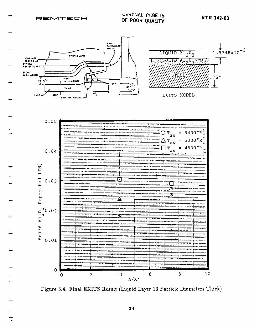
The EXITS computer code has been modified and updated to allow the option
of particle impingement (addition of material) to the surface of the structure. The
code was modified to determine the time required to deposit 0.05 in. of aluminum
oxide (AI203) in the tang/clevis gap, and the amount of AI203 deposited for
different area ratios. (A thickness of 0.05 in. would plug the gap.) Area ratio,mass flow and convective heat transfer calculations were made.
Conclusions of the study show that once the liquid phase is accounted for, it
is improbable that a solid layer of 0.05 in. will build up by direct particle impact
(Fig. 3.4). Consequently, if the gap were to be plugged by alumina solidification,
a different mechanism would be required. The report documenting this work islisted in Table 3.5.
= -
u
m
33
i
F=_='M"T'_"C _ RTR 142-03u_i_:_AL PAGF. IS
OF POOR QUALITY
DtP
i3 1!
LIQUID AI203 1.5748x10
:.!Y:":'.".':..".':."."",';:'A Z 6 :_':":: :k I
EXITS MODEL
i
rl_
0.05
0.04
ZH
v
0.03
-,_
O
_J
coo 0.02
C'4
,-4
<
,-4
O
O.Ol
_ O T = 5400 °R-aw --
...... _-:_"......... _............ - ............... _:..... /\T = -_^^-_UUU°__, _ aw
."-- T = 4600 °R_aw
_-_ --__--_ i.... ,i .... -" ........... L- '_ _--_':-:_- ...........
.... -4 : l + ! ........+ +t +
0 2 4 6 8 i0
A/A*
Figure 3.4: Final EXITS Result (Liquid Layer 10 Particle Diameters Thick)
34

w
RTR 142-03I_ I=" M Ti_- C I--I
Table 3.5: Report on Alumina Solidification in the SRB Field Joint Tang/Clevis
Gap
DOCUMENTATION
D 0 CUMENT i_0. SUBJE'GT DA TE
RTN 142-05 Bancroft, S., Pond, J. and Praharaj,
S., "Particle Impingement Analysis,
Alumina Solidification in Joint Usingthe EXITS Code."
May1986
w
35

RTR 142-03I=_ EE M-I- E C I--i
m
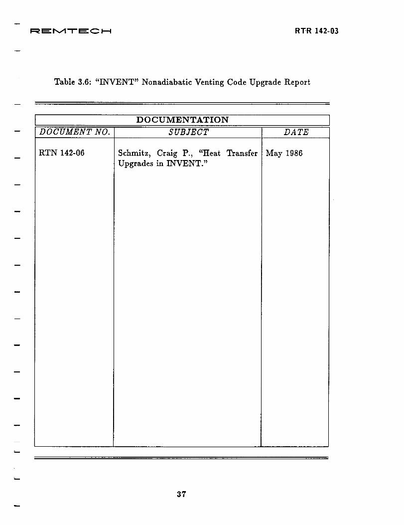
TOPIC: "INVENT" Nonadiabatic Venting Code Upgrade
The INVENT nonadiabatic venting computer code was used in support of the
51-L disaster analysis and SRB redesign effort. In an effort to verify the results
created by INVENT, an analysis was performed on the heat transfer section of the
code. Part of this procedure was to compare the energy balances and calculated
wall temperatures generated by INVENT with similar data generated using the
EXITS computer code and the analytical solution.
In several of the test cases that were performed using INVENT, the heat trans-
fer method desired was for an infinite slab solution. In order for the user to properly
model these conditions, a final temperature profile was added to the INVENT.RSL
output file. The addition of outputting the temperature profile provides several
important capabilities to the user of the INVENT code. One feature is that the
user can ensure that semi-infinite slab conditions have been met and at the same
time optimize the time requirements of the INVENT code. This is accomplished
by the user selecting a "node sizing parameter" and wall thickness that results in
the minimum wall thickness (with sufficient number of nodes to accurately cal-
culate thermal gradient) that still includes a back wall node uninfluenced by the
surface conditions. The report documenting this work is listed in Table 3.6.
36
u
F_ r_- r',,A "-r _:: C _--i RT-R 142-03
Table 3.6: "INVENT" Nonadiabatic Venting Code Upgrade Report
m
DOCUMENTATION
D 0 CUMENT NO. SUBJECT DA TE
RTN 142-06 Schmitz, Craig P., "Heat
Upgrades in INVENT."
Transfer May 1986
37

m
i_:_ e_::r,,._ -i- t_" _ _...4 RTR 142-03
w
Section 4
SRM JOINT REDESIGN ANALYSIS
The fifth task under the contract was to develop computational techniques for
the analysis of the flow of the hot combustion gases of the solid rocket motor
into the rocket segment field and nozzle-to-case joints. Both full- and sub-scale
hot motor firing test programs were initiated to examine the behavior of the hot
gases as they filled the joints, some of the pre-51L design and others of candidate
redesigns. The results of early subscale tests were used to refine the computational
techniques and, later, the codes used to analyze selected full-scale test data and to
make pretest predictions. In December 1987 end unbonds were detected between
the liner and the metal case on the clevis end of motor segments delivered to KSC
for use on STS-26R. The efforts to assess the effects of these unbonds on motor
flight safety were supported using these analytical techniques.
All activities under this task may be categorized into topics as listed below.
1. Subscale Hot Motor Tests
2. Code Improvements
3. Pretest Predictions
4. Full-scale Motor Test Data Analysis
5. Parametric Studies
6. RSRM Field Joint Liner Unbond Analysis
7. SRB Aft Skirt Weld Failure Analysis
As stated in the Introduction, a summary discussion along with a list of pub-
lished reports for each topic are presented.
w
4*
38

TOPIC: Sub,tale Hot Motor Te_t.s
The subscale tests, known as the MSFC 70-1b Motor Tests, simulated the SRM
flow as illustrated in Fig. 4.1. The test field joint was of full-scale dimensions
in the radial direction but the circumferential direction obviously was severely
shortened. To compensate for the unsimulated circumferential volume fill bottles
were attached to match the full-scale values. A total of 21 firings were made to
simulate changes in the joint design as well as test the effects of flaws, or defects, in
the liner seal or the O-rings allowing the hot combustion gases to fill the joint and
heat up the joint materials. The defects considered were based on manufacturing
tolerances and worst-case scenarios. One of the test objective was to demonstrate
the fail-safe performance of the motor even with the defects.
Temperatures and pressures were measured at strategic locations in the gas flow
path and a major objective in the analytical techniques was to develop confidence in
the ability to predict the maximum gas temperature the O-ring would see and the
amount of O-ring erosion that would occur with a given defect geometry. Shown
in Fig. 4.2 is a plot of the measured and predicted gas temperature as it enters
the area in front of the O-ring for a typical subscale test; Table 4.1 compares the
measured and computed O-ring erosion for several of the tests.
Table 4.1: Comparison of Measured and Computed Capture-Feature O-ring Ero-
sion for Several 70-1b Motor Tests
Test
No.
3-3
3-4
3-5
3-6
Erosion, mils
Measured Computed
67.
129.
71.
90.
64.
156.
115.
98.
w
The good agreement demonstrates achievement of that objective. The test
pressures for Tests 3-4 and 3-5 indicated plugging and subsequent reopening of
the flow path, which would cause the erosion to be less than computed assuming
no plugging. The insights learned in the development of this capability will be
discussed under the next Topic.
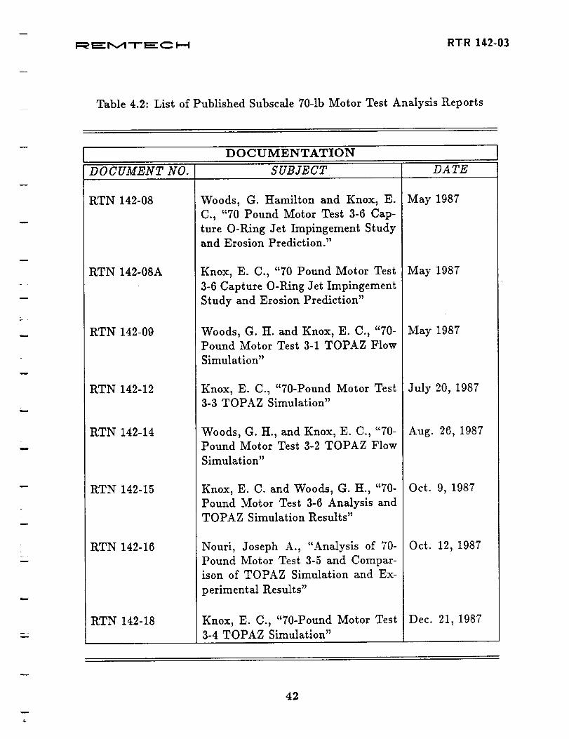
All the documents published under this Topic are listed in Table 4.2.
39

w
F=;__=- r,,,_ -!- _=- C _--! RTR 142-03
Head End
Closure\Spacer
Shims
Case
NBR Insulal
I Total Length = 77 Inches ICase Outer Diameter = !1 inches
Igniter Insert
w
w
u
-Clevis
Test Section-
MSFC 70 Lb. Test Motor Layout.
ALL D|I4EN31ONS IS |H_IE$
Lead Wires
Figure 4.1: NASA/MSFC 70-lb. Motor Test Apparatus
40

i
i=_zE_: r,,,,_ -r- =_" _ I--i RTR 142-03
o
0
:mt,_
tiJ
;>.
Cs
r_
N_0 m
o.,,_
N
41
i
F=__" M"l- _" C _.--I RT-R 142-03
Table 4.2: List of Published Subseale 70-1b Motor Test Analysis Reports
u
u
w
DOCUMENTATION
DOCUMENT NO. SUBJECT DA TE
RTN 142-08
RTN 142-08A
RTN 142-09
RTN 142-12
RTN 142-14
RTN 142-15
RTN 142-16
RTN 142-18
Woods, G. Hamilton and Knox, E.
C., "70 Pound Motor Test 3-6 Cap-
ture O-Ring Jet Impingement Studyand Erosion Prediction."
Knox, E. C., "70 Pound Motor Test
3-6 Capture O-Ring Jet Impingement
Study and Erosion Prediction"
Woods, G. H. and Knox, E. C., "70-
Pound Motor Test 3-1 TOPAZ Flow
Simulation"
Knox, E. C., ¢'70-Pound Motor Test
3-3 TOPAZ Simulation"
Woods, G. H., and Knox, E. C., "70-
Pound Motor Test 3-2 TOPAZ Flow
Simulation"
Knox, E. C. and Woods, G. H., "70-
Pound Motor Test 3-6 Analysis and
TOPAZ Simulation Results"
Nouri, Joseph A., "Analysis of 70-
Pound Motor Test 3-5 and Compar-
ison of TOPAZ Simulation and Ex-
perimental Results"
Knox, E. C., "70-Pound Motor Test
3-4 TOPAZ Simulation"
May 1987
May 1987
May 1987
July 20, 1987
Aug. 26, 1987
Oct. 9, 1987
Oct. 12, 1987
Dec. 21, 1987
¢*
42

w
F_'r,,_I'T'm:'C D--t RTR 142-03
u
TOPIC: Code Improvements
The computational code used in the analytical studies was TOPAZ (TransienL
One-dimensional Pipe flow AnalyZer), developed at Sandia National Laboratories.
The code solves the fully-coupled one-dimensional flow equations (mass, momen-
tum, and energy) through an arbitrary arrangement of pipes, flow branches, and
vessels. The code, as received, provides for mass addition (combustion), frictional
losses and heat transfer to the boundaries (albeit for a constant wall temperature).
Early in the study the constraint of constant wall temperature was removed by
the inclusion of an integral solution of one-dimensional heat conduction into a semi-
infinite slab with a time-variant heat transfer coefficient. Also an empirical method
developed by Morton Thiokol for computing the erosion of insulator-type materials
such as NBR and Viton used for the motor liner and O-rings was modified to permit
a change in the temperature of the gas causing the erosion and incorporated into
an off-line program that uses the output from TOPAZ for the local gas pressure,
velocity, and temperature in front of the O-ring to compute its erosion. The erosion
model's veracity is illustrated by the comparisons given in Table 4.1, page 39.
Another innovation adopted during the study that contributed significantly
to improving the modeling of the hot gas flow was the consideration that the
insulation surfaces over which the hot gases flow ablates and draws some energy
out of the combustion gas to fuel the ablation.
The implementation of the conduction and ablation models in the computa-
tions improved dramatically the agreement with the test results and the erosion
predictions.
The documents published under this Topic are listed in Table 4.3.
43

w
I::_'l,,,A'i-_'_ _ RTR 142-03
Table 4.3: List of Published Code Improvements Reports
w
DOCUMENTATION
DOCUMENT NO. SUBJECT DATE
RTN 142-11
RTN 142-22
Knox, E. C., and Woods, G. H.,
"Comparison of Wall Temperatures
Equation in TOPAZ with the REM-
TECH/EXITS Code"
Nouri, Joseph A., Knox, E. C., and
Woods, G. H., "Analysis of Selected
Results from NASA/MSFC (SRM D
MSFC) Test 15 Using a 1-D FlowCode"
June 1987
February 1988
44

F:_'r',_-t-_:C H R'I'-R 142-03
TOPIC: Pretest Predictiou_
Pretest predictions for two of the 70-lb. motor tests were made, and all of the
predictions indicated fall-safe operation with the built-in defects. Comparisons of
the test results with the predictions were precluded because the flow path into the
joint either sealed or some part of the flow path became plugged for either a part
of the burn or for its duration. Similar predictions were made for the DM-8 firing
but the joints sealed, preventing any gas flow from entering them.
The most comprehensive analytical predictions were clone in support of the
SRM Redesign Critical Design Review (Dec '87). A total of eight different joint
failure scenarios were considered (four field and four nozzle/case joint geometries).
An important observation from the predictions for the field joint was the significant
effect of the metal/metal gap downstream of the capture feature in absorbing
heat from the combustion gas passing through a failed capture-feature O-ring.
The effect was sufficient to render the gas benign as it enters the volume ahead
of the downstream O-rings. Also, the observation illustrated the importance of
maintaining the gap dimensions in the flight hardware.
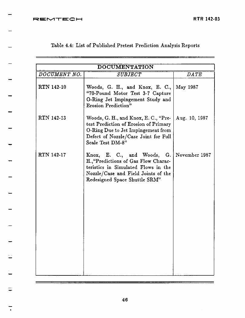
The documents published under this Topic are listed in Table 4.4.
w
45
i=:_mE:r,,._-r--_"_ _ R'rR 142-03
Table 4.4: List of Published Pretest Prediction Analysis Reports
w
DOCUMENTATION
D 0 CUMENT NO. SUBJECT DA TE
RTN 142-10
RTN 142-13
RTN 142-17
Woods, G. H., and Knox, E. C.,
"70-Pound Motor Test 3-7 Capture
O-Pdng Jet Impingement Study andErosion Prediction"
Woods, G. H., and Knox, E. C., "Pre-
test Prediction of Erosion of Primary
O-Ring Due to Jet Impingement from
Defect of Nozzle/Case Joint for FullScale Test DM-8"
Knox, E. C., and Woods, G.
H.,"Predictions of Gas Flow Charac-teristics in Simulated Flows in the
Nozzle/Case and Field Joints of the
Redesigned Space Shuttle SRM"
May 1987
Aug. 10, 1987
November 1987
w
w
6
46

w
l::_ '.=="r',,_ "-I- ".'._"C I-.-I RTR ].4.2-03
TOPIC: Full-scale Motor Test Data Analysis
There were several full-scale motor test firings and other test articles incorpo-
rating portions of the full-scale hardware that were tested to provide additional
data confirming the fail-safe operation of the redesigned joints. The full-scale mo-
tor firings and the JES and NJES test articles were tested at Wasatch and the
TPTA test article as well as the 70-lb. motor tests were done at MSFC.
Of these tests data from JES 3-B was selected for analysis using the analytical
techniques thus far developed. Some controversy surrounded whether or not the
liner material ablated or charred as the hot gases raced through the defect in the
process of filling the field joint. As discussed in a previous section, the amount
of energy predicted to be available for O-ring erosion would be controlled by the
selected model in the analysis. Excellent agreement with the measured gas tem-
perature as it exited the defect was obtained using the ablation model. Shown as
Fig. 4.3 is the comparison.
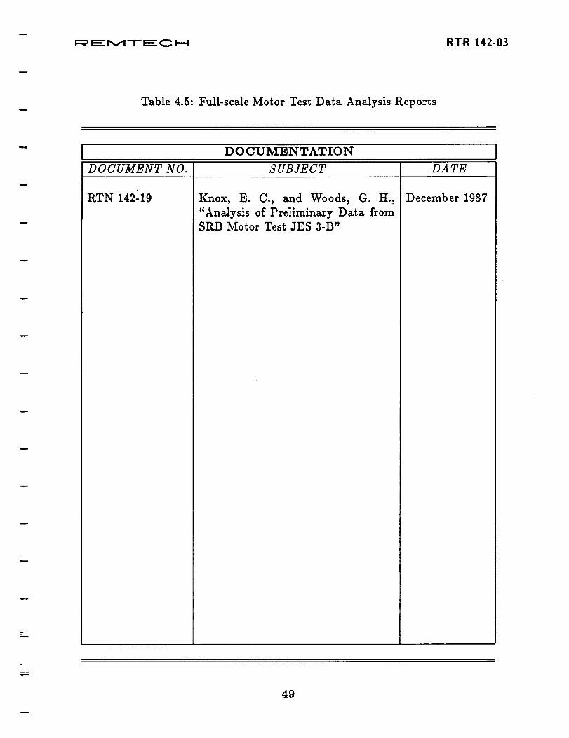
The one document published under this Topic is listed in Table 4.5.
w
i
47

-- F_ E r,,A -r" E C k--_ VISd RTR 142-03
l-
u
o
Ilq
o
i
Ne.,.i e,,,J ,,_
I _, == _:_"
-J I Q
t I
I
o O
m
v _
Lw
\
V3
Z
_J_J
_J
"930
Figure 4.3: Gas Temperature History of JES-3B in Field Joint A Capture Feature
in Line with Insulation Flaw (Source: 3-Hour Data Report)
48
l=_ _'M"r _" C P-4 RTR 142-03
Table 4.5: Full-scale Motor Test Data Analysis Reports
DOCUMENTATION
DOCUMENT NO. SUBJECT DA TE
RTN 142-19 Knox, E. C., and Woods, G. H.,
"Analysis of Preliminary Data fromSRB Motor Test JES 3-B"
December 1987
49

i=_ _- r,v,1 "r" mE:c i--i RTR 142-03
TOPIC: Parametric Studies
Another objective in developing the analytical capability of computing the
transient gas flow conditions in SRM joints was to perform sensitivity studies on
the several pararnetrics that affect the gas flow. One such study was done under
this Topic to examine the effect of defect size through the J-seal on the "fill time",
time required for the differential from the motor bore pressure to that in the joint to
become zero, and the maximum value of that differential during the filling process.
Other parametric studies were performed but they related to the unbond con-
dition and are described under the Topic for that subject.
The one document published under this Topic is listed in Table 4.6.
w
50

F_E_:r,,A'-r-E:C I--..-I RT-R 14.2-03
Table 4.6: Parametric Studies Analysis Report
i
r_
u
DOCUMENTATION
D 0 CUMENT NO. SUBJECT DA TE
RTN 142-20 Knox, E. C., "Parametric Study ofFlow in SRM J-Seal Joints"
Dec. 31, 1987
.,i
m
51
i=_ n_- r,,,A-I- n_- _ D--i R'FR 142-03
TOPIC: I_$RM Field Joint Liner Unbonds
As mentioned earlier, the RSRM segments shipped to KSC for the first post-51L
shuttle flight were detected to have edge unbonds of the case liner from the steel
case. Some unbonds were found on the tang side of the joint as well but the major
unbonds were on the clevis side. These unbonds far exceeded the pre-51L unbond
acceptance criteria. To reject them based on those criteria would cause significant
launch delay, so efforts were initiated to estimate the effect of the presence of the
unbonds in the joint filling process should a leak defect exist at the joint. Further,
because these segments with the new joint design required a new manufacturing
process, the question arose if the prior acceptance criteria were reasonable and, if
not, what was.
The evolved code, TOPAZ, was used extensively in support of these efforts. The
flow parameters obtained from the code were used in both 2- and 3-D conduction
codes to determine steel interior temperatures around the joint with edge unbonds.
These temperatures were supplied to Morton Thiokol for use in their structural
stress analysis.
The pace of producing results for this effort was so rapid as to preclude the
opportunity to document them until its completion. So only a report defining the
techniques used to model the unbond and a summary report of the work under
this Topic was published. These reports are listed in Table 4.7.
52

w
F=_'P,,A-r_'C I_ RTR 142-03
Table 4.7: List of Published RSRM Unbond Analysis Reports
L
i
DOCUMENTATION
DOCUMENT NO. SUBJECT DA TE
RTN 142-21
RTN 142-24
Woods, G. tI., "Full Scale Modified
J Seal Field Joint Insulation/ClevisDebond Model"
Knox, E. C., and Woods, G. H.,
"Summary of Analysis Support for
RSRM Clevis Unbonds - June/July1988"
December 1987
August 1988
53

I=_ _=="i',v,l"r- _" _ F..._ RTR 142-03
TOPIC: SPd3 Aft Skirt Weld Failure Analysis
During the load testing of an SRB aft skirt, one of the weld seams next to a hold-
down post failed over about 70 percent of its length, leaving a gap through which
external gases could flow into the interior. REMTECH was asked to estimate the
thermal consequences of such a scenario. The analysis and results are documented
in the publication listed in Table 4.8.
54

w
F:__" t,,,A"l- _" C I.--I R'FR 142-03
Table 4.8: SPLB Aft Skirt Weld Failure Analysis Report
!
DOCUMENTATION
D 0 C UMENT NO. SUBJECT DA TE
I%TN 142-23 Woods, Hamilton, and Crain, Will-
iam K., "SRB Aft Skirt Weld Seam
Failure Analysis"
August 1988
55