-f data sheet avec deltwavec-f
TRANSCRIPT

systec Controls GmbH Lindberghstrasse 4, 82178 Puchheim Telefon 089 - 80906-0, Telefax 089 - 80906-200 eMail: [email protected] http://www.systec-controls.de Rev. 1.60 / 04.02.2016
Clamp-on flowmeter for liquids in filled pipes
Data sheet deltwaveC-F
de
lta
wa
ve
C-F
Ultrasonic clamp-on flowmeter for liquids
1- Channel, 2- Channel, Ex

systec Controls GmbH Lindberghstr. 4, 82178 Puchheim, Germany Telefon +49 89 - 80906-0, Telefax +49 89 - 80906-200 eMail: [email protected] http://www.systec-controls.de 2 / 12
Clamp-on flowmeter for liquids in filled pipes
Overview
Range of applications
� -40 to 150 °C � Pipe Size DN10 – DN6000 � Pipe Material: Most common materials (ultrasonic conductible) like steel, plastics (PE, PVC,
PEEK,…) � Flow velocities: 0….+/-30 m/s � Media: Liquids � Accuracy: Up to 1% � Certificates: CE / ATEX (in preparation) � Heat quantity measurement � Operation in hazardous areas (Ex) � 5-point calibration (factory certificate)
Typical Applications
Power Plants � Cooling water � Boiler feed water � Condensate and heat circuits
Water and waste water industry � Influent, Effluent, Sludge � Consumption and distribution measurements � Chemical flows (small pipes, low flows) � Leakage detection � Treatment dosage control
Facility Management � Pump Control � Optimization of heating and air conditionig � Optimization of energy efficiency Chemical and petrochemical industry � Basic materials as well as intermediate and final products � Hydrocarbon liquids � Measurement on high pressure systems
Food and Beverage � Consumption optimization
Pharmaceutical and semiconductor industry � Non-invasive measurement of ultra pure fluids
Introduction
Picture 1 Mounted transducers with spacer bar at steel pipe.
systec Controls GmbH Lindberghstr. 4, 82178 Puchheim, Germany Telefon +49 89 - 80906-0, Telefax +49 89 - 80906-200 eMail: [email protected] http://www.systec-controls.de 3 / 12
Clamp-on flowmeter for liquids in filled pipes
Measurement principle
deltawaveC-F uses the effect of acceleration and decelaration of acoustic signals travelling in a moving fluid. Two ultrasonic clamp on transducers are mounted (from outside) on a pipe, as shown in Pictures 2/3/4 and produces an acoustic path. The transducers sending and receiving acoustic signals, the transit times T1 and T2 are measured by an electronic flow transmitter. The signal from transducer A towards transducer B is ac-celerated by the flow (short T1) the return signal from transducer B to transducer A is decelerated by the flow (longer T2). The difference between T1 and T2 together with the path length L can be used to determine the average flow velocity v. This principle is known as the acoustic time-of-flight principle. The flow is calculated from the geometry data of the pipe and the flow velocity. High level signal processing: deltawaveC-F emits coded signal pattern into the pipe. The received signals will be compared with the sent signals and only signal pattern which correlate with the original sent pattern will be used for flow calculation (cross correlation based signal evaluation). The calculation of the flow is done with the integrated DSP (digital signal processor). Thus the calculation has high sampling rates. The DSP calculation of the time-of-flight is a pure digital transit time measurement it works very precise, is completely drift and maintenance free and there is no need for recurring calibrations.
Features
� Clear text based user interface with LED backlight QVGA display � User interface control with 6 soft buttons � Quick- Mount- System with space bar for ultrasonic transducers F10 and F21 � AFC compensation algorithm: compensates influences of changing
media temperatures to the ultrasonic transducer distance � Reynolds compensation: compensates influences of media viscosity
on the ultrasonic measurement � Ultrasonic transducers AND technology: reducing signal echoes and dispersion
effects and having a positive effect on the signal to noise ratio. � 2 channel version � Applicable for ex hazardous areas (only deltawaveC-F flow transmitter
respectively ultrasonic transducers)

systec Controls GmbH Lindberghstr. 4, 82178 Puchheim, Germany Telefon +49 89 - 80906-0, Telefax +49 89 - 80906-200 eMail: [email protected] http://www.systec-controls.de 4 / 12
Clamp-on flowmeter for liquids in filled pipes
deltawaveC-F overview
deltawaveC-F 1-Channel flow transmitter Flow measurement, thermal output and heat quantity measurement is applicable for one measurement point in combination with one pair ultrasonic transducers and one pair PT100.
deltawaveC-F 2-Channel flow transmitter
Flow measurement is applicable for one or two different measurement points with two pairs of ultrasonic transducers. deltawaveC-F 2 channel version supports different mathematical operations like CH1+CH2, CH1-CH2, (CH1+CH2)/2; due to the appliance of two pair ultrasonic- transducers mounted. Opposite mounting of 2 pairs of transducers on the same pipe the accuracy of measurement will be increas-ing, a redundancy operation is possible or disruptive influences depending small inlet path lengths will be compensated. Thermal output and heat quantity measurement is only supported in operation mode (CH1+CH2)/2.
deltawaveC-F flow transmitter, 1 Channel, 2 Channel The deltwaveC-F Ex flow transmitter could be applied up to Ex Zone 1. The technology of deltawaveC-F Ex flow transmitter is installed in a special Ex housing. The electronics are implemented in the pressure encapsulated area of the housing (Ex d). The cable terminal compartment is located in the area of the housing with extended security (Ex e). To read off the measurement thuresults from the display from del-tawaveC-F Ex the housing is equipped with a gauge glass. For parameterization it is necessary to remove the gauge glass (screw cap).
The ultrasonic transducers
deltawaveC-F standard ultrasonic transducers The standard ultrasonic transducers can be used together with each deltawaveC-F flow transmitter. The standard ultrasonic transmitters are not applicable for usage in ex hazardous areas.
deltawaveC-F ultrasonic transducers The deltawaveC-F ultrasonic transducers with Ex approval can be operate up to Ex Zone 1. If a standard deltawaveC-F flow transmitter without Ex approval (located outside the ex hazardous area - safe area) is used, than it is allowed to operate it together with ultrasonic transducers with Ex approval (located in an Ex hazardous area). deltawaveC-F Ex flow transmitter with ex approval could be operated together with ultrasonic transducers with ex approval up to Ex Zone 1.

systec Controls GmbH Lindberghstr. 4, 82178 Puchheim, Germany Telefon +49 89 - 80906-0, Telefax +49 89 - 80906-200 eMail: [email protected] http://www.systec-controls.de 5 / 12
Clamp-on flowmeter for liquids in filled pipes
Picture 2 Mounting in V-Mode (standard installation applicable for most applications)
Picture 3: Mounting in Z-Mode (applicable for big pipe dimensions or high acoustic damping caused by pipe material and/or media)
Picture 4: Mounting in W-Mode (preferred mounting method for pipe dimensions <DN32)
D v [m/s] L
T2
D v [m/s] L T1
T2
T1
Transducers
4…20mA / Puls / RS232 /RS485
Flow, Velocity, Volume
Transducers
4…20mA / Puls / RS232 /RS485
Flow, Velocity, Volume
D v [m/s]
L T2 T1
Transducers
4…20mA / Puls / RS232 /RS485
Flow, Velocity, Volume
T1

systec Controls GmbH Lindberghstr. 4, 82178 Puchheim, Germany Telefon +49 89 - 80906-0, Telefax +49 89 - 80906-200 eMail: [email protected] http://www.systec-controls.de 6 / 12
Clamp-on flowmeter for liquids in filled pipes
Kanal 1 Kanal 2
2
21vv
v
+=
Measuring mode 2- channel system Picture 5: Simultaneous measurement at 2 different measurement points with two pair ultrasonic transducers
Picture 6: Simultaneous measurement with two pairs of ultrasonic transducers at one common metering point => accuracy will be increased, a redundancy operation is possible or disruptive influences depending small inlet path lengths will be compensated.
D
v1 v2
Channel 1
Flow, Velocity, Volume 4…20mA / Puls / RS232 /RS485
Flow, Velocity, Volume 4…20mA / Puls / RS232 /RS485
Channel 2

systec Controls GmbH Lindberghstr. 4, 82178 Puchheim, Germany Telefon +49 89 - 80906-0, Telefax +49 89 - 80906-200 eMail: [email protected] http://www.systec-controls.de 7 / 12
Clamp-on flowmeter for liquids in filled pipes
Measurement of heat quantity
deltawaveC-F is more than a flow meter. Together with external temperature sensors it can also measures the heat transfer of your media. Only two external PT100 have to be connected to deltawaveC-F for measur-ing feed / return temperatures (RTD 1 / RTD 2) within the heating circuit. The measured temperature differ-ence and the measured flow Q can then be used to calculate the thermal output and the heat quantity. systec Controls offers comfortable clamp-On PT100 for these applications as an option.
Picture 7: Measurement of heat quantity – Measurement principle
RTD 2
RTD 1
systec Controls GmbH Lindberghstr. 4, 82178 Puchheim, Germany Telefon +49 89 - 80906-0, Telefax +49 89 - 80906-200 eMail: [email protected] http://www.systec-controls.de 8 / 12
Clamp-on flowmeter for liquids in filled pipes
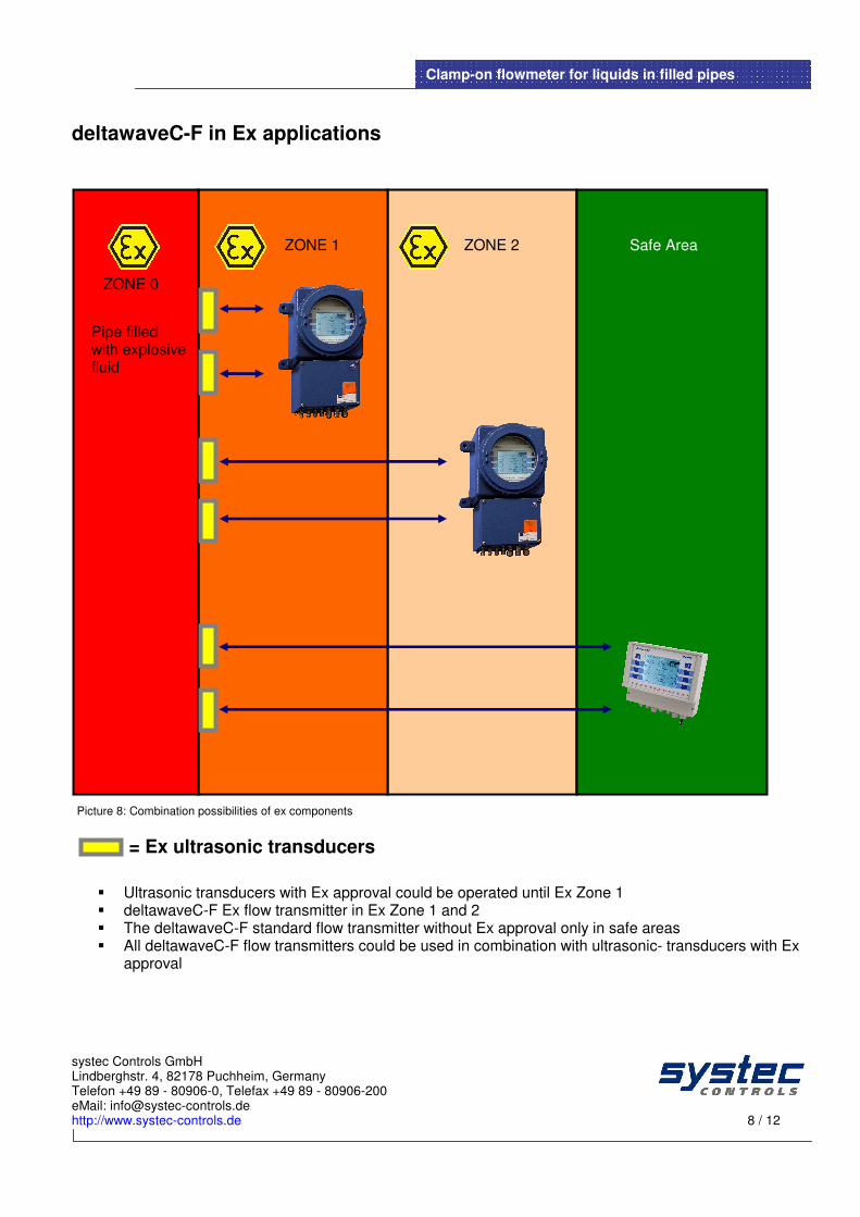
deltawaveC-F in Ex applications
Picture 8: Combination possibilities of ex components
= Ex ultrasonic transducers
� Ultrasonic transducers with Ex approval could be operated until Ex Zone 1 � deltawaveC-F Ex flow transmitter in Ex Zone 1 and 2 � The deltawaveC-F standard flow transmitter without Ex approval only in safe areas � All deltawaveC-F flow transmitters could be used in combination with ultrasonic- transducers with Ex
approval
ZONE 2 ZONE 1 Safe Area
ZONE 0
Pipe filled with explosive fluid

systec Controls GmbH Lindberghstr. 4, 82178 Puchheim, Germany Telefon +49 89 - 80906-0, Telefax +49 89 - 80906-200 eMail: [email protected] http://www.systec-controls.de 9 / 12
Clamp-on flowmeter for liquids in filled pipes
Electronic Flow transmitter – Specifications
Measurement principle Ultrasonic Time-of-flight
Signal processing DSP based, cross correlation
Physical Quantities Flow, velocity, Fluid velocity, Thermal Output, Heat Rate, Flow direction, Accumulated Flow
Counter Volume, Heat Quantity
Measurement range -30…+30 m/s
Calibration function PT100, flow
Signal damping 0…100 sec (adjustable)
Diagnostic functions In extracts: Sound velocity, Signal Amplitutde, SNR, Signal Quality (SQ), Signal Scan @ Display
Human interface Intuitive via 6 Soft buttons
Menu languages D, UK, FR, RU, ES, CHN
Flow transmitter units Metric /UK /US
Outputs 2x 4…20mA (active or passive, connection with ground poten-tial) 1x Pulse (Connection with ground potential) 1x Relays (Potential free) 1x optional RS232oder RS485 (Master Slave)
BUS Communication MODBUS (RTU, ASCII) via optional RS485 interface [Format: Request, Function 04)
Data Logger Optional Data Logger with 4GB capacity (available August 2015) – Not applicable together with MODBUS and serial communication
Inputs 2x US transducer, 2x PT100 (for measurement of heat quanti-ty), Power Supply
Power supply 90-230VAC or 18-36VDC
Degree of protection IP65
Cable connections Screw terminals
Dimensions [L x W x D] 260x240x120mm
Calibration Optional ISO 9000 based factory calibration certificate (per or-der)
Table 1 Common specifications of flow transmitter deltawaveC-F
deltawaveC 1- channel and 2- channel
Housing PVC, Wallmount
Operating temperature -20…60°C
Weight 1.3kg
Power consumption ca. 10W (1 channel) /ca. 13W (2 channel)
Dimensions [L x W x D] 260 x 240 x 120mm
Table 2 Specifications for deltawaveC-F 1-Channel and 2-Channel standard flow transmitter
systec Controls GmbH Lindberghstr. 4, 82178 Puchheim, Germany Telefon +49 89 - 80906-0, Telefax +49 89 - 80906-200 eMail: [email protected] http://www.systec-controls.de 10 / 12
Clamp-on flowmeter for liquids in filled pipes
Additional deltawave 2-Channel
Measuring modes CH1, CH2, CH1+CH2, CH1-CH2, (CH1+CH2)/2
Inputs 4x US transducer, 2x PT100 (for measurement of heat quanti-ty), Power supply
Outputs (additional) 2 x Pulse
Weight 1.5kg Table 3 Additional specifications for deltawaveC-F 2-Channel standard flow transmitter
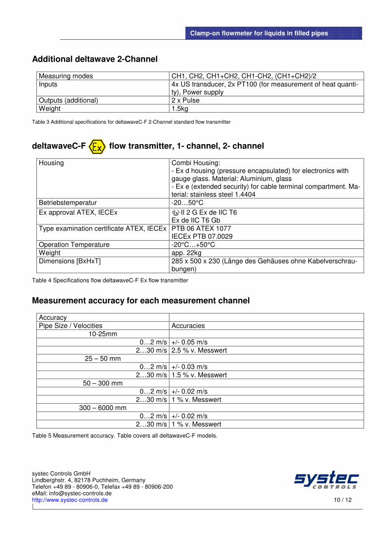
deltawaveC-F flow transmitter, 1- channel, 2- channel
Housing Combi Housing: - Ex d housing (pressure encapsulated) for electronics with gauge glass. Material: Aluminium, glass - Ex e (extended security) for cable terminal compartment. Ma-terial: stainless steel 1.4404
Betriebstemperatur -20…50°C
Ex approval ATEX, IECEx II 2 G Ex de IIC T6 Ex de IIC T6 Gb
Type examination certificate ATEX, IECEx PTB 06 ATEX 1077 IECEx PTB 07.0029
Operation Temperature -20°C…+50°C
Weight app. 22kg
Dimensions [BxHxT] 285 x 500 x 230 (Länge des Gehäuses ohne Kabelverschrau-bungen)
Table 4 Specifications flow deltawaveC-F Ex flow transmitter
Measurement accuracy for each measurement channel
Accuracy
Pipe Size / Velocities Accuracies
10-25mm
0…2 m/s +/- 0.05 m/s
2…30 m/s 2.5 % v. Messwert
25 – 50 mm
0…2 m/s +/- 0.03 m/s
2…30 m/s 1.5 % v. Messwert
50 – 300 mm
0…2 m/s +/- 0.02 m/s
2…30 m/s 1 % v. Messwert
300 – 6000 mm
0…2 m/s +/- 0.02 m/s
2…30 m/s 1 % v. Messwert
Table 5 Measurement accuracy. Table covers all deltawaveC-F models.

systec Controls GmbH Lindberghstr. 4, 82178 Puchheim, Germany Telefon +49 89 - 80906-0, Telefax +49 89 - 80906-200 eMail: [email protected] http://www.systec-controls.de 11 / 12
Clamp-on flowmeter for liquids in filled pipes
Ultrasonic transducers – specifications US- transducer model Pipe size
Type Pipe Sizes Media Temperature Cable length Material Housing
Acoustic Coupling
F21 2 MHz
DN10…DN100 -40…150°C 5m PEEK / Aluminium
Gel / Foil (opt.)
F10 1 MHz
DN32…DN400 -40…150°C
5m PEEK / Aluminium
Gel / Foil (opt.)
F05 500 kHz
DN200…DN6000 -40…150°C 5m PEEK / Aluminium
Gel / Foil (opt.)
Table 6: Specifications of ultrasonic transducers
Additional specifications for ultrasonic transducers with approval
Ex approval ATEX, IECEx II EX d IIC T6…T3 Gb
EG- type examination certificate ATEX, IECEx
EPS 13 ATEX 1 557 X IECEx XXX XX.XXXX X (certificate number depends on Charge) 2004
Ambient temperature -40 °C ≤ Ta ≤ +80 °C (fluid temperature max. 150°C)
Degree of protection IP68
Table 7: Specifications of ultrasonic transducers with ex approval
Picture 9: 1 MHz-ultrasonic transducers with spacer bar on water pipe, DN125
F05
F10
F21
DN10…DN100
DN32…DN400
DN200…DN6000

systec Controls GmbH Lindberghstr. 4, 82178 Puchheim, Germany Telefon +49 89 - 80906-0, Telefax +49 89 - 80906-200 eMail: [email protected] http://www.systec-controls.de 12 / 12
Clamp-on flowmeter for liquids in filled pipes
Further information
� www.systec-controls.de
Any questions? We are happy to support you! At www.systec-controls.de (Infos&Contact) you can search for your contact person or your systec representa-tive or you can send an inquiry directly to systec Controls Of course also our sales team in the systec headquarter in Puchheim, Germany would be happy to support you. systec Controls Mess- und Regeltechnik GmbH Lindberghstr. 4 82178 Puchheim Phone: ++49-(0)89-80 90 60 / Fax: ++49-(0)89-80 90 6-200 [email protected] http://www.systec-controls.de