f-801m h/-c service manual - hoshizaki …-c)_serv.pdf2 important only qualified service technicians...
TRANSCRIPT
Hoshizaki
“A Superior Degreeof Reliability”
www.hoshizaki.com
ModelsF-801MAH(-C)F-801MWH(-C)
Modular Flaker
Hoshizaki America, Inc.
Number: 73113Issued: 7-29-2004Revised: 6-15-2005
SERVICE MANUAL

2
IMPORTANTOnly qualified service technicians should attempt to service or maintain thisicemaker. No service or maintenance should be undertaken until the technicianhas thoroughly read this Service Manual.
HOSHIZAKI provides this manual primarily to assist qualified service technicians in theservice and maintenance of the icemaker.
Should the reader have any questions or concerns which have not been satisfactorilyaddressed, please call or write to the HOSHIZAKI Technical Support Department forassistance.
HOSHIZAKI AMERICA, INC.618 Highway 74 SouthPeachtree City, GA 30269
Attn: HOSHIZAKI Technical Support Department
Phone: 1-800-233-1940 Technical Service (770) 487-2331
Fax: 1-800-843-1056 (770) 487-3360
Web Site: www.hoshizakiamerica.com
Note: To expedite assistance, all correspondence/communication MUST include thefollowing information:
• Model Number
• Serial Number
• Complete and detailed explanation of the problem

3
CONTENTSI. Specification ...................................................................................................................... 5
1. Icemaker ....................................................................................................................... 5F-801MAH.................................................................................................................. 5F-801MWH................................................................................................................. 6F-801MAH-C .............................................................................................................. 7F-801MWH-C ............................................................................................................. 8
II. General Information .......................................................................................................... 91. Construction ................................................................................................................. 9
F-801MAH/-C ............................................................................................................. 9F-801MWH/-C .......................................................................................................... 10
2. Control Box Layout ..................................................................................................... 11F-801MAH/-C ........................................................................................................... 11F-801MWH/-C .......................................................................................................... 12
III. Technical Information ..................................................................................................... 131. Water Circuit and Refrigeration Circuit ........................................................................ 13
F-801MAH/-C ........................................................................................................... 13F-801MWH/-C .......................................................................................................... 14
2. Wiring Diagrams ......................................................................................................... 15F-801MAH/-C, F-801MWH/-C .................................................................................. 15
3. Sequence of Electrical Circuit .................................................................................... 164. Timing Chart ............................................................................................................... 265. Performance Data ....................................................................................................... 29
F-801MAH................................................................................................................ 29F-801MWH............................................................................................................... 30F-801MAH-C ............................................................................................................ 31F-801MWH-C ........................................................................................................... 32
IV. Adjustment of Components ............................................................................................ 331. Adjustment of Water Regulating Valve (water-cooled model only) .............................. 332. Adjustment of Flake Size ............................................................................................ 34
V. Service Diagnosis........................................................................................................... 351. No Ice Production ....................................................................................................... 352. Low Ice Production ..................................................................................................... 373. Other ........................................................................................................................... 38
VI. Removal and Replacement of Components .................................................................. 391. Service for Refrigerant Lines ...................................................................................... 39
[a] Refrigerant Recovery........................................................................................... 39[b] Evacuation and Recharge [R-404A] .................................................................... 39
2. Brazing ....................................................................................................................... 403. Removal and Replacement of Compressor ................................................................ 414. Removal and Replacement of Drier ........................................................................... 42
Please review this manual. It should be read carefully before the icemaker is serviced ormaintenance operations are performed. Only qualified service technicians should serviceand maintain the icemaker. This manual should be made available to the technician priorto service or maintenance.

4
5. Removal and Replacement of Expansion Valve......................................................... 436. Removal and Replacement of Water Regulating Valve (water-cooled model only) .... 447. Removal and Replacement of Evaporator Assembly ................................................. 458. Removal and Replacement of Fan Motor ................................................................... 499. Removal and Replacement of Control Water Valve .................................................... 4910. Removal and Replacement of Flush Water Valve ..................................................... 50
VII. Cleaning and Maintenance .......................................................................................... 511. Preparing the Icemaker for Long Storage ................................................................... 512. Cleaning and Sanitizing Instructions .......................................................................... 52
[a] Cleaning Solution ................................................................................................ 52[b] Cleaning Procedure ............................................................................................ 53[c] Sanitizing Solution............................................................................................... 54[d] Sanitizing Procedure - Initial ................................................................................ 54[e] Sanitizing Procedure - Final ................................................................................ 55
3. Maintenance ............................................................................................................... 57
5
I. Specification1. Icemaker
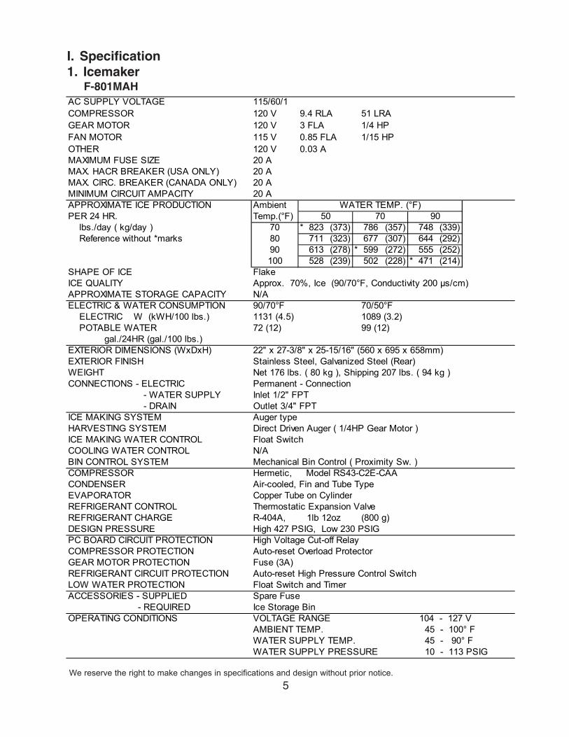
F-801MAH
We reserve the right to make changes in specifications and design without prior notice.
AC SUPPLY VOLTAGE 115/60/1 COMPRESSOR 120 V 9.4 RLA 51 LRAGEAR MOTOR 120 V 3 FLA 1/4 HPFAN MOTOR 115 V 0.85 FLA 1/15 HPOTHER 120 V 0.03 AMAXIMUM FUSE SIZE 20 AMAX. HACR BREAKER (USA ONLY) 20 AMAX. CIRC. BREAKER (CANADA ONLY) 20 AMINIMUM CIRCUIT AMPACITY 20 AAPPROXIMATE ICE PRODUCTION AmbientPER 24 HR. Temp.(°F) lbs./day ( kg/day ) 70 * 823 (373) 786 (357) 748 (339) Reference without *marks 80 711 (323) 677 (307) 644 (292)
90 613 (278) * 599 (272) 555 (252)100 528 (239) 502 (228) * 471 (214)
SHAPE OF ICE FlakeICE QUALITY Approx. 70%, Ice (90/70°F, Conductivity 200 µs/cm)APPROXIMATE STORAGE CAPACITY N/AELECTRIC & WATER CONSUMPTION 90/70°F 70/50°F ELECTRIC W (kWH/100 lbs.) 1131 (4.5) 1089 (3.2) POTABLE WATER 72 (12) 99 (12) gal./24HR (gal./100 lbs.)EXTERIOR DIMENSIONS (WxDxH) 22" x 27-3/8" x 25-15/16" (560 x 695 x 658mm)EXTERIOR FINISH Stainless Steel, Galvanized Steel (Rear)WEIGHT Net 176 lbs. ( 80 kg ), Shipping 207 lbs. ( 94 kg )CONNECTIONS - ELECTRIC Permanent - Connection - WATER SUPPLY Inlet 1/2" FPT - DRAIN Outlet 3/4" FPTICE MAKING SYSTEM Auger typeHARVESTING SYSTEM Direct Driven Auger ( 1/4HP Gear Motor )ICE MAKING WATER CONTROL Float SwitchCOOLING WATER CONTROL N/ABIN CONTROL SYSTEM Mechanical Bin Control ( Proximity Sw. )COMPRESSOR Hermetic, Model RS43-C2E-CAACONDENSER Air-cooled, Fin and Tube TypeEVAPORATOR Copper Tube on CylinderREFRIGERANT CONTROL Thermostatic Expansion ValveREFRIGERANT CHARGE R-404A, (800 g)DESIGN PRESSURE High 427 PSIG, Low 230 PSIGPC BOARD CIRCUIT PROTECTION High Voltage Cut-off RelayCOMPRESSOR PROTECTION Auto-reset Overload ProtectorGEAR MOTOR PROTECTION Fuse (3A)REFRIGERANT CIRCUIT PROTECTION Auto-reset High Pressure Control SwitchLOW WATER PROTECTION Float Switch and TimerACCESSORIES - SUPPLIED Spare Fuse - REQUIRED Ice Storage BinOPERATING CONDITIONS VOLTAGE RANGE 104 - 127 V
AMBIENT TEMP. 45 - 100° FWATER SUPPLY TEMP. 45 - 90° FWATER SUPPLY PRESSURE 10 - 113 PSIG
1lb 12oz
50WATER TEMP. (°F)
70 90
6
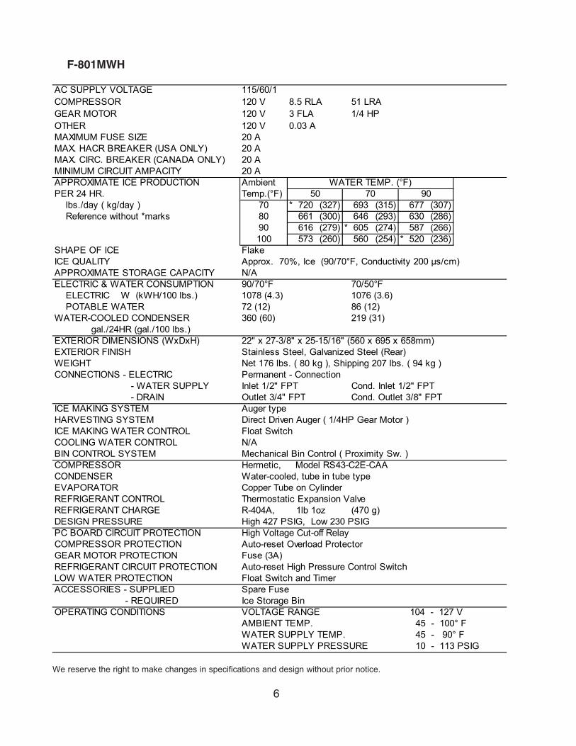
F-801MWH
We reserve the right to make changes in specifications and design without prior notice.
AC SUPPLY VOLTAGE 115/60/1 COMPRESSOR 120 V 8.5 RLA 51 LRAGEAR MOTOR 120 V 3 FLA 1/4 HPOTHER 120 V 0.03 AMAXIMUM FUSE SIZE 20 AMAX. HACR BREAKER (USA ONLY) 20 AMAX. CIRC. BREAKER (CANADA ONLY) 20 AMINIMUM CIRCUIT AMPACITY 20 AAPPROXIMATE ICE PRODUCTION AmbientPER 24 HR. Temp.(°F) lbs./day ( kg/day ) 70 * 720 (327) 693 (315) 677 (307) Reference without *marks 80 661 (300) 646 (293) 630 (286)
90 616 (279) * 605 (274) 587 (266)100 573 (260) 560 (254) * 520 (236)
SHAPE OF ICE FlakeICE QUALITY Approx. 70%, Ice (90/70°F, Conductivity 200 µs/cm)APPROXIMATE STORAGE CAPACITY N/AELECTRIC & WATER CONSUMPTION 90/70°F 70/50°F ELECTRIC W (kWH/100 lbs.) 1078 (4.3) 1076 (3.6) POTABLE WATER 72 (12) 86 (12)WATER-COOLED CONDENSER 360 (60) 219 (31) gal./24HR (gal./100 lbs.)EXTERIOR DIMENSIONS (WxDxH) 22" x 27-3/8" x 25-15/16" (560 x 695 x 658mm)EXTERIOR FINISH Stainless Steel, Galvanized Steel (Rear)WEIGHT Net 176 lbs. ( 80 kg ), Shipping 207 lbs. ( 94 kg )CONNECTIONS - ELECTRIC Permanent - Connection - WATER SUPPLY Inlet 1/2" FPT Cond. Inlet 1/2" FPT - DRAIN Outlet 3/4" FPT Cond. Outlet 3/8" FPTICE MAKING SYSTEM Auger typeHARVESTING SYSTEM Direct Driven Auger ( 1/4HP Gear Motor )ICE MAKING WATER CONTROL Float SwitchCOOLING WATER CONTROL N/ABIN CONTROL SYSTEM Mechanical Bin Control ( Proximity Sw. )COMPRESSOR Hermetic, Model RS43-C2E-CAACONDENSER Water-cooled, tube in tube typeEVAPORATOR Copper Tube on CylinderREFRIGERANT CONTROL Thermostatic Expansion ValveREFRIGERANT CHARGE R-404A, (470 g)DESIGN PRESSURE High 427 PSIG, Low 230 PSIGPC BOARD CIRCUIT PROTECTION High Voltage Cut-off RelayCOMPRESSOR PROTECTION Auto-reset Overload ProtectorGEAR MOTOR PROTECTION Fuse (3A)REFRIGERANT CIRCUIT PROTECTION Auto-reset High Pressure Control SwitchLOW WATER PROTECTION Float Switch and TimerACCESSORIES - SUPPLIED Spare Fuse - REQUIRED Ice Storage BinOPERATING CONDITIONS VOLTAGE RANGE 104 - 127 V
AMBIENT TEMP. 45 - 100° FWATER SUPPLY TEMP. 45 - 90° FWATER SUPPLY PRESSURE 10 - 113 PSIG
1lb 1oz
50WATER TEMP. (°F)
70 90
7
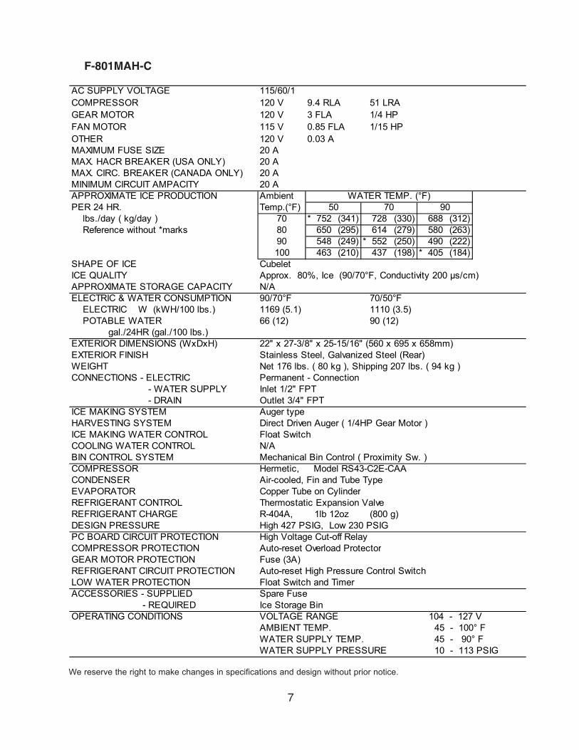
F-801MAH-C
We reserve the right to make changes in specifications and design without prior notice.
AC SUPPLY VOLTAGE 115/60/1 COMPRESSOR 120 V 9.4 RLA 51 LRAGEAR MOTOR 120 V 3 FLA 1/4 HPFAN MOTOR 115 V 0.85 FLA 1/15 HPOTHER 120 V 0.03 AMAXIMUM FUSE SIZE 20 AMAX. HACR BREAKER (USA ONLY) 20 AMAX. CIRC. BREAKER (CANADA ONLY) 20 AMINIMUM CIRCUIT AMPACITY 20 AAPPROXIMATE ICE PRODUCTION AmbientPER 24 HR. Temp.(°F) lbs./day ( kg/day ) 70 * 752 (341) 728 (330) 688 (312) Reference without *marks 80 650 (295) 614 (279) 580 (263)
90 548 (249) * 552 (250) 490 (222)100 463 (210) 437 (198) * 405 (184)
SHAPE OF ICE CubeletICE QUALITY Approx. 80%, Ice (90/70°F, Conductivity 200 µs/cm)APPROXIMATE STORAGE CAPACITY N/AELECTRIC & WATER CONSUMPTION 90/70°F 70/50°F ELECTRIC W (kWH/100 lbs.) 1169 (5.1) 1110 (3.5) POTABLE WATER 66 (12) 90 (12) gal./24HR (gal./100 lbs.)EXTERIOR DIMENSIONS (WxDxH) 22" x 27-3/8" x 25-15/16" (560 x 695 x 658mm)EXTERIOR FINISH Stainless Steel, Galvanized Steel (Rear)WEIGHT Net 176 lbs. ( 80 kg ), Shipping 207 lbs. ( 94 kg )CONNECTIONS - ELECTRIC Permanent - Connection - WATER SUPPLY Inlet 1/2" FPT - DRAIN Outlet 3/4" FPTICE MAKING SYSTEM Auger typeHARVESTING SYSTEM Direct Driven Auger ( 1/4HP Gear Motor )ICE MAKING WATER CONTROL Float SwitchCOOLING WATER CONTROL N/ABIN CONTROL SYSTEM Mechanical Bin Control ( Proximity Sw. )COMPRESSOR Hermetic, Model RS43-C2E-CAACONDENSER Air-cooled, Fin and Tube TypeEVAPORATOR Copper Tube on CylinderREFRIGERANT CONTROL Thermostatic Expansion ValveREFRIGERANT CHARGE R-404A, (800 g)DESIGN PRESSURE High 427 PSIG, Low 230 PSIGPC BOARD CIRCUIT PROTECTION High Voltage Cut-off RelayCOMPRESSOR PROTECTION Auto-reset Overload ProtectorGEAR MOTOR PROTECTION Fuse (3A)REFRIGERANT CIRCUIT PROTECTION Auto-reset High Pressure Control SwitchLOW WATER PROTECTION Float Switch and TimerACCESSORIES - SUPPLIED Spare Fuse - REQUIRED Ice Storage BinOPERATING CONDITIONS VOLTAGE RANGE 104 - 127 V
AMBIENT TEMP. 45 - 100° FWATER SUPPLY TEMP. 45 - 90° FWATER SUPPLY PRESSURE 10 - 113 PSIG
50WATER TEMP. (°F)
70 90
1lb 12oz
8
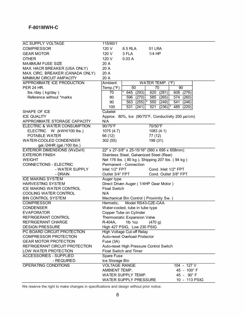
F-801MWH-C
We reserve the right to make changes in specifications and design without prior notice.
AC SUPPLY VOLTAGE 115/60/1 COMPRESSOR 120 V 8.5 RLA 51 LRAGEAR MOTOR 120 V 3 FLA 1/4 HPOTHER 120 V 0.03 AMAXIMUM FUSE SIZE 20 AMAX. HACR BREAKER (USA ONLY) 20 AMAX. CIRC. BREAKER (CANADA ONLY) 20 AMINIMUM CIRCUIT AMPACITY 20 AAPPROXIMATE ICE PRODUCTION AmbientPER 24 HR. Temp.(°F) lbs./day ( kg/day ) 70 * 645 (293) 620 (281) 608 (276) Reference without *marks 80 596 (270) 585 (265) 574 (260)
90 563 (255) * 550 (249) 541 (246)100 531 (241) 521 (236) * 485 (220)
SHAPE OF ICE CubeletICE QUALITY Approx. 80%, Ice (90/70°F, Conductivity 200 µs/cm)APPROXIMATE STORAGE CAPACITY N/AELECTRIC & WATER CONSUMPTION 90/70°F 70/50°F ELECTRIC W (kWH/100 lbs.) 1075 (4.7) 1083 (4.1) POTABLE WATER 66 (12) 77 (12)WATER-COOLED CONDENSER 302 (55) 199 (31) gal./24HR (gal./100 lbs.)EXTERIOR DIMENSIONS (WxDxH) 22" x 27-3/8" x 25-15/16" (560 x 695 x 658mm)EXTERIOR FINISH Stainless Steel, Galvanized Steel (Rear)WEIGHT Net 176 lbs. ( 80 kg ), Shipping 207 lbs. ( 94 kg )CONNECTIONS - ELECTRIC Permanent - Connection - WATER SUPPLY Inlet 1/2" FPT Cond. Inlet 1/2" FPT - DRAIN Outlet 3/4" FPT Cond. Outlet 3/8" FPTICE MAKING SYSTEM Auger typeHARVESTING SYSTEM Direct Driven Auger ( 1/4HP Gear Motor )ICE MAKING WATER CONTROL Float SwitchCOOLING WATER CONTROL N/ABIN CONTROL SYSTEM Mechanical Bin Control ( Proximity Sw. )COMPRESSOR Hermetic, Model RS43-C2E-CAACONDENSER Water-cooled, tube in tube typeEVAPORATOR Copper Tube on CylinderREFRIGERANT CONTROL Thermostatic Expansion ValveREFRIGERANT CHARGE R-404A, (470 g)DESIGN PRESSURE High 427 PSIG, Low 230 PSIGPC BOARD CIRCUIT PROTECTION High Voltage Cut-off RelayCOMPRESSOR PROTECTION Auto-reset Overload ProtectorGEAR MOTOR PROTECTION Fuse (3A)REFRIGERANT CIRCUIT PROTECTION Auto-reset High Pressure Control SwitchLOW WATER PROTECTION Float Switch and TimerACCESSORIES - SUPPLIED Spare Fuse - REQUIRED Ice Storage BinOPERATING CONDITIONS VOLTAGE RANGE 104 - 127 V
AMBIENT TEMP. 45 - 100° FWATER SUPPLY TEMP. 45 - 90° FWATER SUPPLY PRESSURE 10 - 113 PSIG
1lb 1oz
50WATER TEMP. (°F)
70 90

9
II. General Information1. Construction
F-801MAH/-C
Water SupplyInlet
Junction Box
Condenser
Fan Motor
Compressor
Drier
Control Water Valve
Bin Control
Ice Chute
Evaporator
ExpansionValve
Flush WaterValve
Control Box
Gear Motor
10
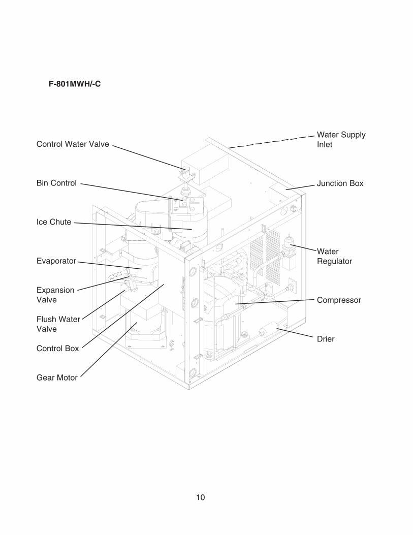
F-801MWH/-C
Water SupplyInlet
Junction Box
WaterRegulator
Compressor
Drier
Control Water Valve
Bin Control
Ice Chute
Evaporator
ExpansionValve
Flush WaterValve
Control Box
Gear Motor
11
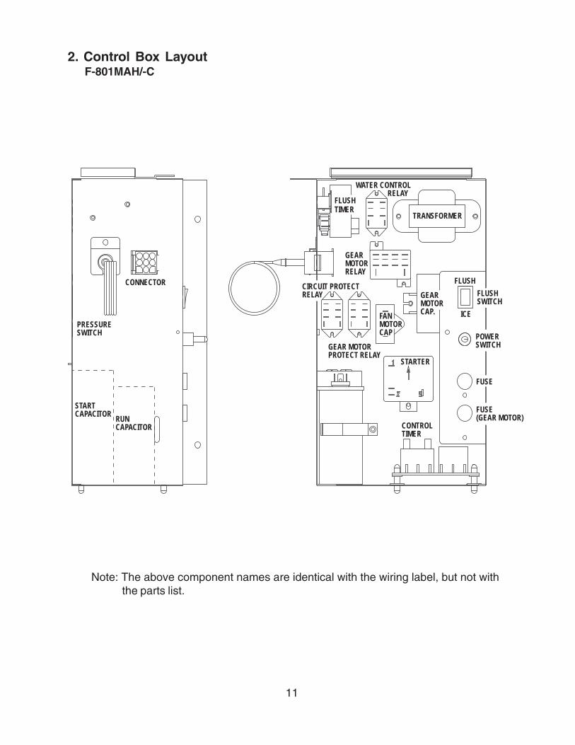
2. Control Box LayoutF-801MAH/-C
Note: The above component names are identical with the wiring label, but not withthe parts list.
PRESSURESWITCH
CONNECTOR
STARTCAPACITOR
RUNCAPACITOR
WATER CONTROL RELAY
FLUSHTIMER
TRANSFORMER
GEARMOTORRELAY
GEARMOTORCAP.
FLUSH
ICEFANMOTORCAP
GEAR MOTORPROTECT RELAY
STARTER
CONTROLTIMER
FUSE(GEAR MOTOR)
FUSE
POWERSWITCH
FLUSHSWITCH
CIRCUIT PROTECTRELAY

12
F-801MWH/-C
������������
�������
�� �� � ����
��� � ����
� ������������������������������� �
�� ��������
�� ��������� �
����
��
�� ����������������� �
�� ����
�����������
��������
���������
����
������� ��������
���������
��������������� �
�� ������ ��
13
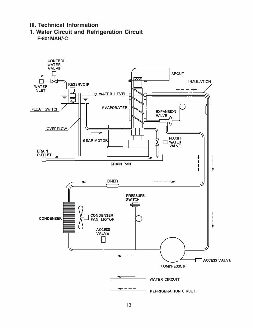
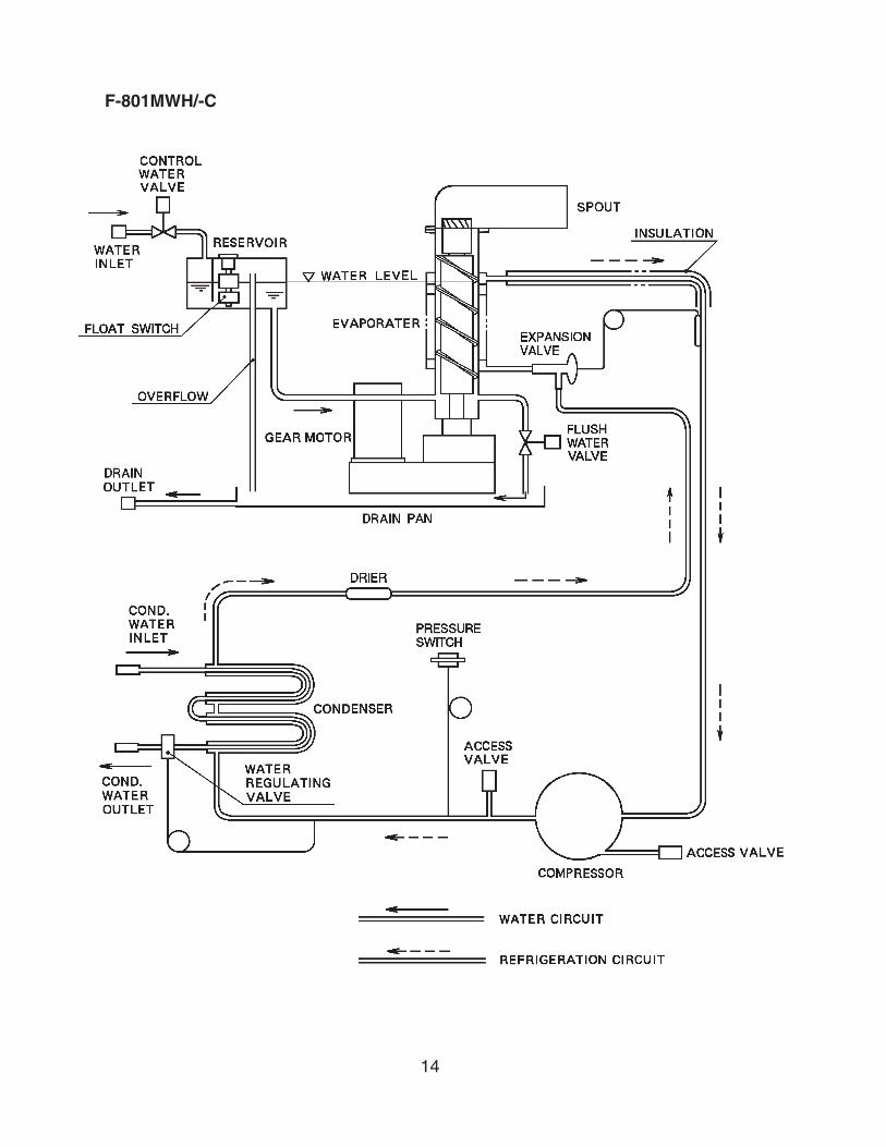
III. Technical Information1. Water Circuit and Refrigeration Circuit
F-801MAH/-C
14
F-801MWH/-C

15
2. Wiring DiagramsF-801MAH/-C, F-801MWH/-C
16
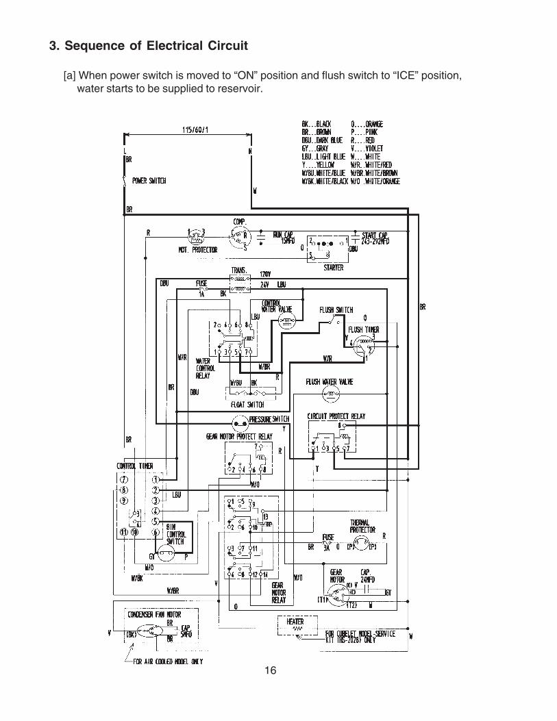
3. Sequence of Electrical Circuit
[a] When power switch is moved to “ON” position and flush switch to “ICE” position, water starts to be supplied to reservoir.
17
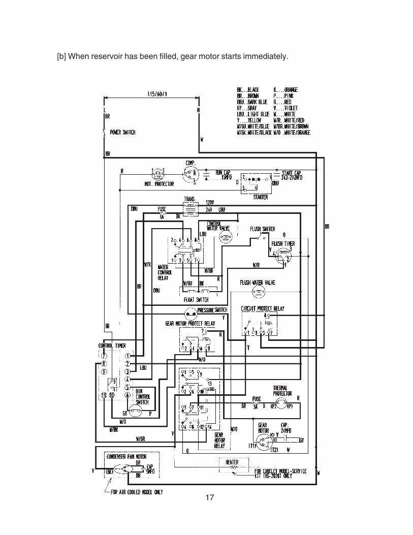
[b] When reservoir has been filled, gear motor starts immediately.

18
[c] Compressor starts about 60 sec. after gear motor starts.
19
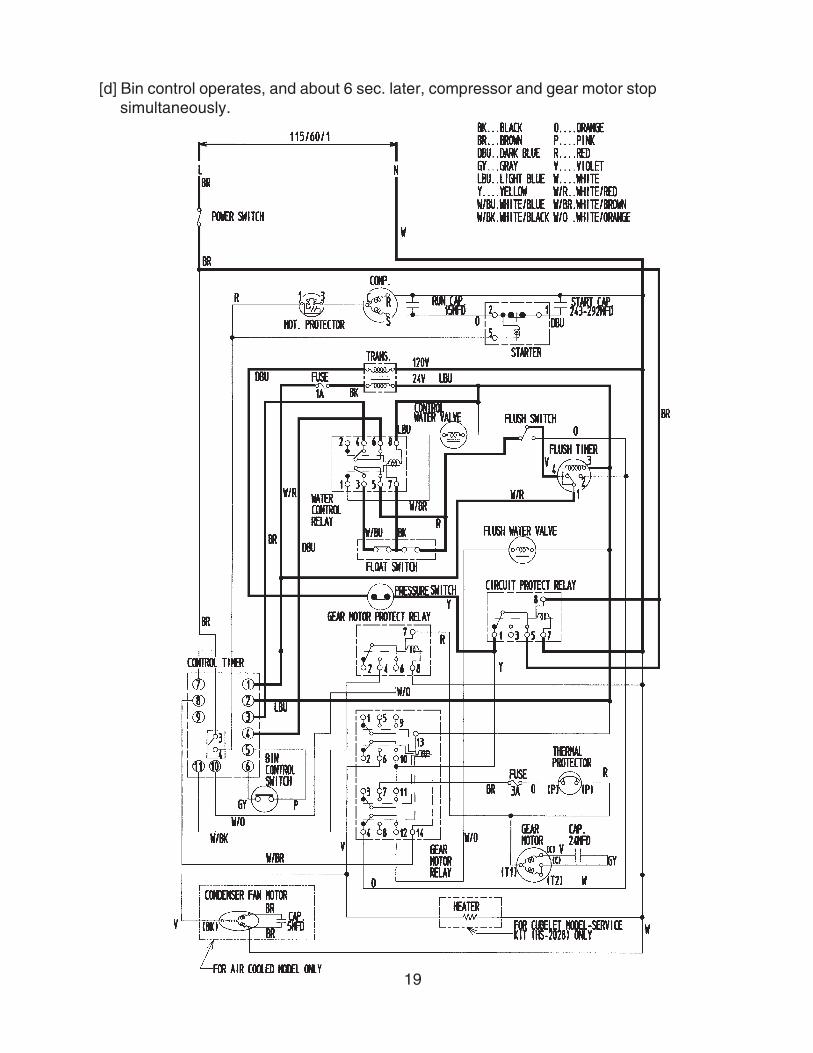
[d] Bin control operates, and about 6 sec. later, compressor and gear motor stopsimultaneously.
20
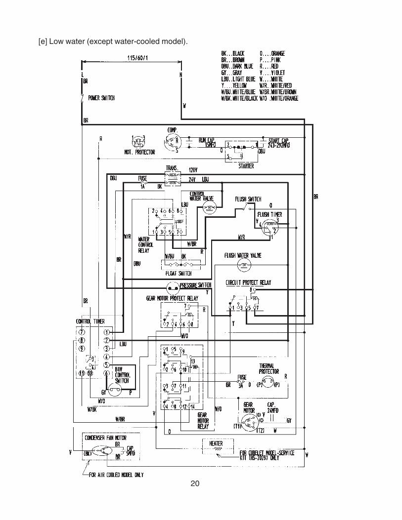
[e] Low water (except water-cooled model).
21
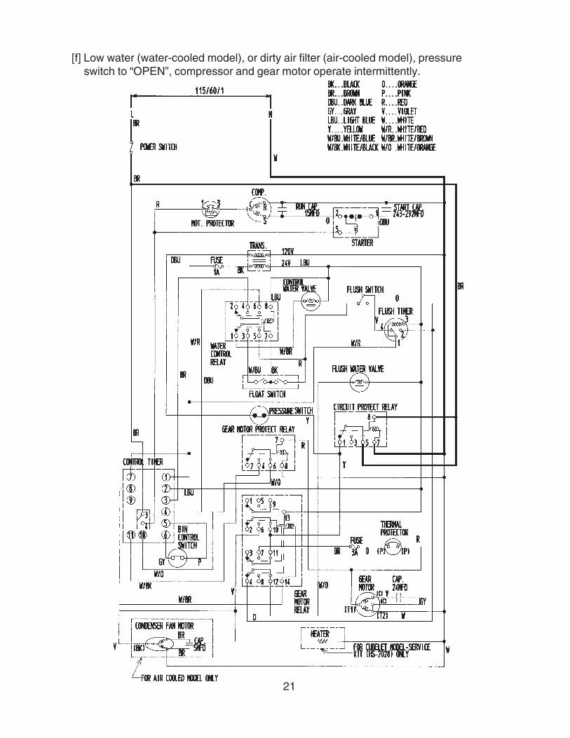
[f] Low water (water-cooled model), or dirty air filter (air-cooled model), pressure switch to “OPEN”, compressor and gear motor operate intermittently.
22
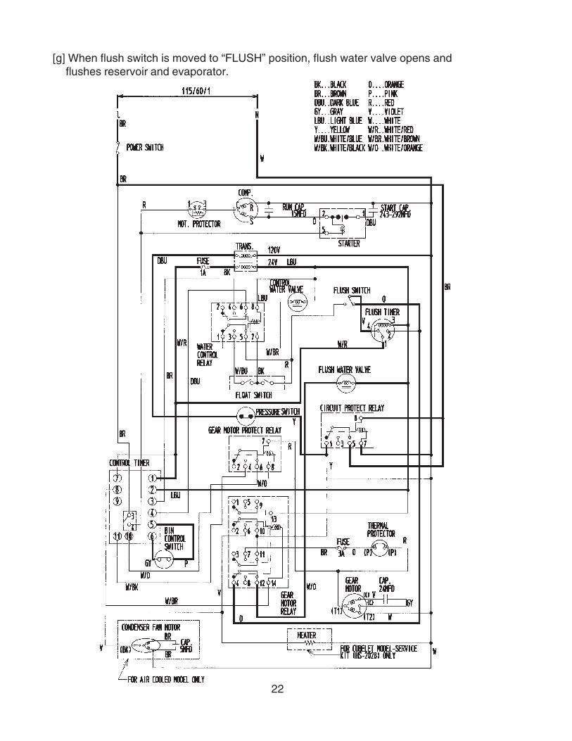
[g] When flush switch is moved to “FLUSH” position, flush water valve opens and flushes reservoir and evaporator.

23
[h] When flush timer operates (for 15 min. every 12 hours).

24
[i] When 208-230V are supplied to circuit protect relay, it protects the circuit from miswiring. If the power supply is properly connected, the contact of circuit protect relay does not move even when the coil is energized.

25
[j] When input voltage is too low, (less than 70%), gear motor fuse (1.5A) is blown causing the compressor and gear motor to turn off immediately.
26
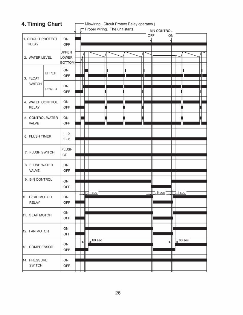
Miswiring. Circuit Protect Relay operates.)Proper wiring. The unit starts. BIN CONTROL
OFF ON1. CIRCUIT PROTECT
RELAY
2. WATER LEVEL
3. FLOAT
SWITCH
UPPER
LOWER
4. WATER CONTROL
RELAY
5. CONTROL WATER
VALVE
6. FLUSH TIMER
7. FLUSH SWITCH
8. FLUSH WATER
VALVE
9. BIN CONTROL
10. GEAR MOTOR
RELAY
11. GEAR MOTOR
12. FAN MOTOR
13. COMPRESSOR
14. PRESSURE
SWITCH
ON
OFF
ON
OFF
ON
OFF
ON
OFF
ON
OFF
1 - 2
2 - 3
FLUSH
ICE
ON
OFF
ON
OFF
ON
OFF
ON
OFF
ON
OFF
ON
OFF
ON
OFF
1 sec
60 sec
6 sec 1 sec
60 sec
UPPER
LOWER
BOTTOM
4. Timing Chart

27
1. CIRCUIT PROTECT
RELAY
2. WATER LEVEL
3. FLOAT
SWITCH
UPPER
LOWER
4. WATER CONTROL
RELAY
5. CONTROL WATER
VALVE
6. FLUSH TIMER
7. FLUSH SWITCH
8. FLUSH WATER
VALVE
9. BIN CONTROL
10. GEAR MOTOR
RELAY
11. GEAR MOTOR
12. FAN MOTOR
14. PRESSURE
SWITCH
ON
OFF
ON
OFF
ON
OFF
ON
OFF
ON
OFF
1 - 2
2 - 3
FLUSH
ICE
ON
OFF
ON
OFF
ON
OFF
ON
OFF
ON
OFF
ON
OFF
ON
OFF
UPPER
LOWERBOTTOM
LOW WATER FLUSH TIMER
21 min every 12 hr
150 sec 1 sec 150 sec
90 sec 60 sec 90 sec 60 sec
1 sec
13. COMPRESSOR

28
1. CIRCUIT PROTECT
RELAY
2. WATER LEVEL
3. FLOAT
SWITCH
UPPER
LOWER
4. WATER CONTROL
RELAY
5. CONTROL WATER
VALVE
6. FLUSH TIMER
7. FLUSH SWITCH
8. FLUSH WATER
VALVE
9. BIN CONTROL
10. GEAR MOTOR
RELAY
11. GEAR MOTOR
12. FAN MOTOR
14. PRESSURE
SWITCH
ON
OFF
ON
OFF
ON
OFF
ON
OFF
ON
OFF
1 - 2
2 - 3
FLUSH
ICE
ON
OFF
ON
OFF
ON
OFF
ON
OFF
ON
OFF
ON
OFF
ON
OFF
UPPER
LOWERBOTTOM
FLUSH SWITCH PRESSURE SWITCHFLUSH ICE OFF ON
150 sec 1 sec
90 sec 60 sec
13. COMPRESSOR
1 sec
1 sec
60 sec

29
5. Performance DataF-801MAH
We reserve the right to make changes in specifications and design without prior notice.
APPROXIMATE Ambient Water Temp. (F)ICE PRODUCTION Temp. (F)PER 24 HR. 70 * 823 (373) 786 (357) 748 (339)
80 711 (323) 677 (307) 644 (292)90 613 (278) * 599 (272) 555 (252)
lbs./day ( kg/day) 100 528 (239) 502 (228) * 471 (214)APPROXIMATE ELECTRIC 70 * 1089 -- 1095 -- 1101 --CONSUMPTION 80 1107 -- 1113 -- 1119 --
90 1125 -- * 1131 -- 1147 --watts 100 1164 -- 1181 -- * 1197 --APPROXIMATE WATER 70 * 99 (374) 94 (357) 90 (340)CONSUMPTION PER 24 HR. 80 85 (323) 81 (308) 77 (293)(TOTAL) 90 74 (278) * 72 (272) 67 (252)gal. / day (l/day) 100 63 (240) 60 (228) * 57 (214)EVAPORATOR OUTLET TEMP. 70 * 15 (-10) 16 (-9) 16 (-9)°F (°C) 80 16 (-9) 16 (-9) 17 (-8)
90 17 (-8) * 17 (-8) 18 (-8)100 19 (-7) 19 (-7) * 20 (-7)
HEAD PRESSURE 70 * 204 (14.3) 266 (18.7) 302 (21.2)80 204 (14.3) 266 (18.7) 302 (21.2)90 204 (14.3) * 266 (18.7) 302 (21.2)
PSIG (kg/cm2G) 100 204 (14.3) 266 (18.7) * 302 (21.2)SUCTION PRESSURE 70 * 38 (2.7) 42 (3.0) 46 (3.3)PSIG (kg/cm2G) 80 38 (2.7) 42 (3.0) 46 (3.3)
90 38 (2.7) * 42 (3.0) 46 (3.3)100 38 (2.7) 42 (3.0) * 46 (3.3)
6398 BTU/h (AT 90°F / WT 70°F)
Note: The data without *marks should be used for reference.
TOTAL HEAT OF REJECTION
50 70 90
30
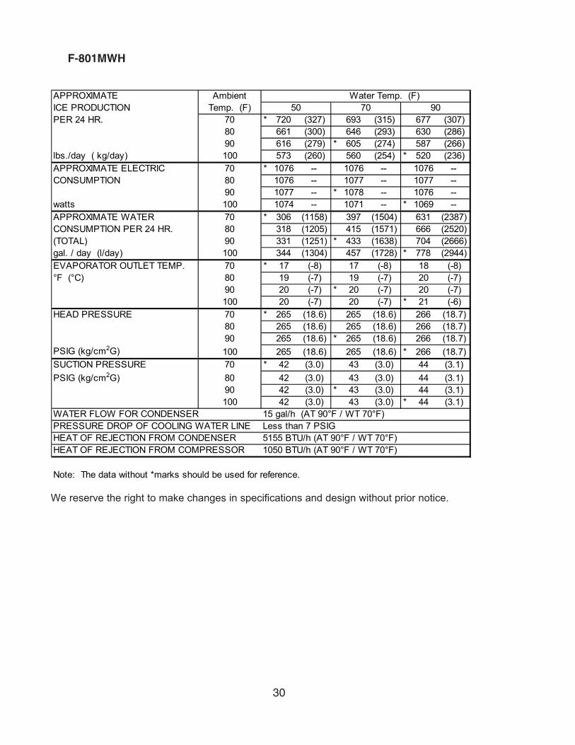
F-801MWH
We reserve the right to make changes in specifications and design without prior notice.
APPROXIMATE Ambient Water Temp. (F)ICE PRODUCTION Temp. (F)PER 24 HR. 70 * 720 (327) 693 (315) 677 (307)
80 661 (300) 646 (293) 630 (286)90 616 (279) * 605 (274) 587 (266)
lbs./day ( kg/day) 100 573 (260) 560 (254) * 520 (236)APPROXIMATE ELECTRIC 70 * 1076 -- 1076 -- 1076 --CONSUMPTION 80 1076 -- 1077 -- 1077 --
90 1077 -- * 1078 -- 1076 --watts 100 1074 -- 1071 -- * 1069 --APPROXIMATE WATER 70 * 306 (1158) 397 (1504) 631 (2387)CONSUMPTION PER 24 HR. 80 318 (1205) 415 (1571) 666 (2520)(TOTAL) 90 331 (1251) * 433 (1638) 704 (2666)gal. / day (l/day) 100 344 (1304) 457 (1728) * 778 (2944)EVAPORATOR OUTLET TEMP. 70 * 17 (-8) 17 (-8) 18 (-8)°F (°C) 80 19 (-7) 19 (-7) 20 (-7)
90 20 (-7) * 20 (-7) 20 (-7)100 20 (-7) 20 (-7) * 21 (-6)
HEAD PRESSURE 70 * 265 (18.6) 265 (18.6) 266 (18.7)80 265 (18.6) 265 (18.6) 266 (18.7)90 265 (18.6) * 265 (18.6) 266 (18.7)
PSIG (kg/cm2G) 100 265 (18.6) 265 (18.6) * 266 (18.7)SUCTION PRESSURE 70 * 42 (3.0) 43 (3.0) 44 (3.1)PSIG (kg/cm2G) 80 42 (3.0) 43 (3.0) 44 (3.1)
90 42 (3.0) * 43 (3.0) 44 (3.1)100 42 (3.0) 43 (3.0) * 44 (3.1)
Note: The data without *marks should be used for reference.
HEAT OF REJECTION FROM COMPRESSOR 1050 BTU/h (AT 90°F / WT 70°F)
WATER FLOW FOR CONDENSER 15 gal/h (AT 90°F / WT 70°F)PRESSURE DROP OF COOLING WATER LINE Less than 7 PSIGHEAT OF REJECTION FROM CONDENSER
50 70 90
5155 BTU/h (AT 90°F / WT 70°F)
31
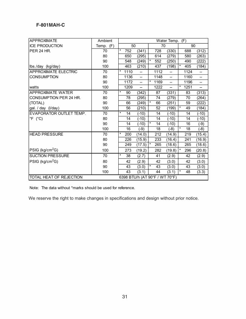
F-801MAH-C
We reserve the right to make changes in specifications and design without prior notice.
APPROXIMATE Ambient Water Temp. (F)ICE PRODUCTION Temp. (F)PER 24 HR. 70 * 752 (341) 728 (330) 688 (312)
80 650 (295) 614 (279) 580 (263)90 548 (249) * 552 (250) 490 (222)
lbs./day (kg/day) 100 463 (210) 437 (198) * 405 (184)APPROXIMATE ELECTRIC 70 * 1110 -- 1112 -- 1124 --CONSUMPTION 80 1136 -- 1148 -- 1160 --
90 1172 -- * 1169 -- 1196 --watts 100 1209 -- 1222 -- * 1251 --APPROXIMATE WATER 70 * 90 (342) 87 (331) 83 (313)CONSUMPTION PER 24 HR. 80 78 (295) 74 (279) 70 (264)(TOTAL) 90 66 (249) * 66 (251) 59 (222)gal. / day (l/day) 100 56 (210) 52 (199) * 49 (184)EVAPORATOR OUTLET TEMP. 70 * 14 (-10) 14 (-10) 14 (-10)°F (°C) 80 14 (-10) 14 (-10) 14 (-10)
90 14 (-10) * 14 (-10) 16 (-9)100 16 (-9) 18 (-8) * 18 (-8)
HEAD PRESSURE 70 * 200 (14.0) 212 (14.9) 219 (15.4)80 226 (15.9) 233 (16.4) 241 (16.9)90 249 (17.5) * 265 (18.6) 265 (18.6)
PSIG (kg/cm2G) 100 273 (19.2) 282 (19.8) * 296 (20.8)SUCTION PRESSURE 70 * 38 (2.7) 41 (2.9) 42 (2.9)PSIG (kg/cm2G) 80 42 (2.9) 42 (3.0) 42 (3.0)
90 43 (3.0) * 43 (3.0) 43 (3.0)100 43 (3.1) 44 (3.1) * 48 (3.3)
6398 BTU/h (AT 90°F / WT 70°F)
Note: The data without *marks should be used for reference.
TOTAL HEAT OF REJECTION
50 70 90

32
F-801MWH-C
We reserve the right to make changes in specifications and design without prior notice.
APPROXIMATE Ambient Water Temp. (F)ICE PRODUCTION Temp. (F)PER 24 HR. 70 * 645 (293) 620 (281) 608 (276)
80 596 (270) 585 (265) 574 (260)90 563 (255) * 550 (249) 541 (246)
lbs./day ( kg/day) 100 531 (241) 521 (236) * 485 (220)APPROXIMATE ELECTRIC 70 * 1083 -- 1082 -- 1081 --CONSUMPTION 80 1080 -- 1078 -- 1077 --
90 1076 -- * 1075 -- 1073 --watts 100 1072 -- 1070 -- * 1068 --APPROXIMATE WATER 70 * 276 (1046) 342 (1294) 579 (2192)CONSUMPTION PER 24 HR. 80 287 (1086) 354 (1339) 605 (2291)(TOTAL) 90 296 (1119) * 368 (1392) 633 (2397)gal. / day (l/day) 100 305 (1156) 381 (1442) * 693 (2622)EVAPORATOR OUTLET TEMP. 70 * 20 (-7) 20 (-7) 21 (-6)°F (°C) 80 21 (-6) 21 (-6) 21 (-6)
90 21 (-6) * 21 (-6) 21 (-6)100 21 (-6) 21 (-6) * 22 (-6)
HEAD PRESSURE 70 * 263 (18.5) 263 (18.5) 264 (18.6)80 263 (18.5) 263 (18.5) 264 (18.6)90 263 (18.5) * 263 (18.5) 264 (18.6)
PSIG (kg/cm2G) 100 263 (18.5) 263 (18.5) * 264 (18.6)SUCTION PRESSURE 70 * 46 (3.2) 46 (3.3) 47 (3.3)PSIG (kg/cm2G) 80 46 (3.2) 46 (3.3) 47 (3.3)
90 46 (3.2) * 46 (3.3) 47 (3.3)100 46 (3.2) 46 (3.3) * 47 (3.3)
Note: The data without *marks should be used for reference.
50 70 90
13 gal/h (AT 90°F / WT 70°F)Less than 7 PSIG5155 BTU/h (AT 90°F / WT 70°F)
WATER FLOW FOR CONDENSERPRESSURE DROP OF COOLING WATER LINEHEAT OF REJECTION FROM CONDENSERHEAT OF REJECTION FROM COMPRESSOR 1050 BTU/h (AT 90°F / WT 70°F)
33
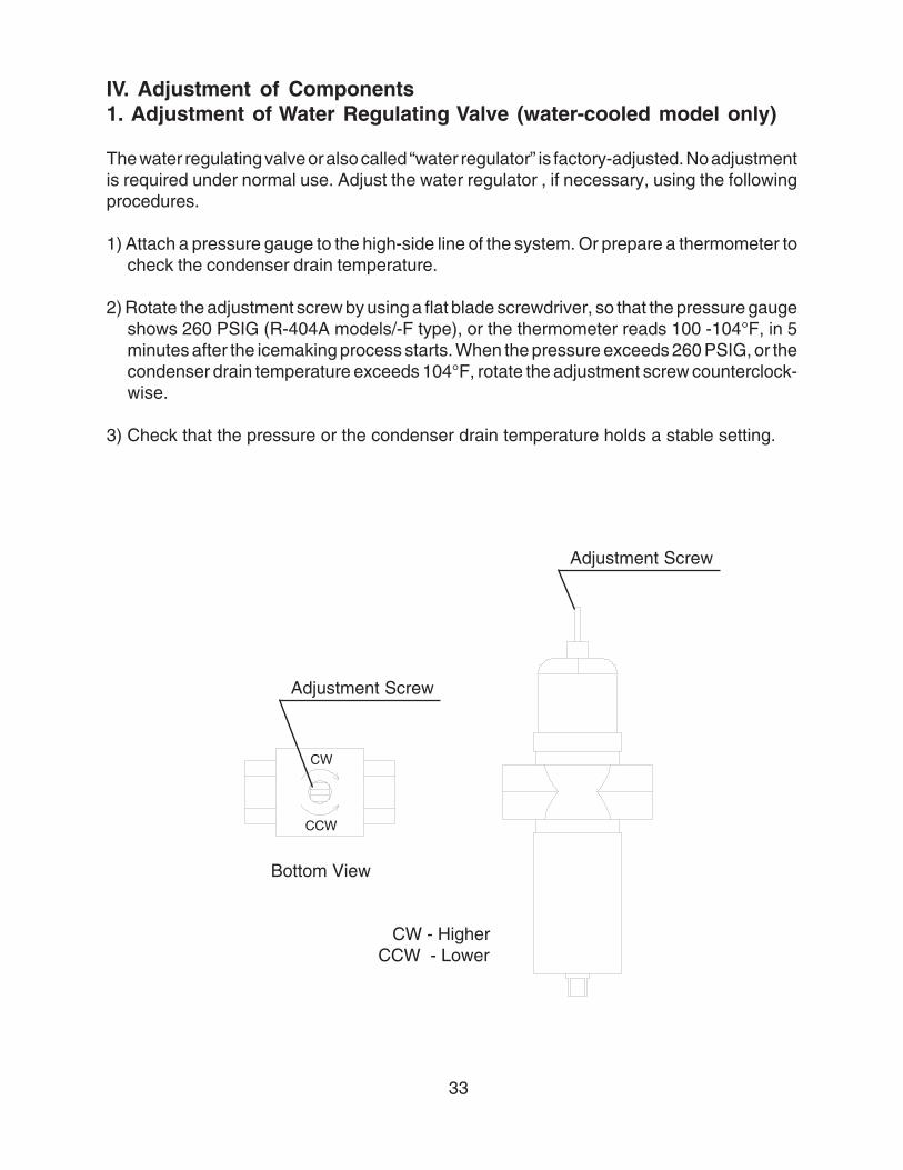
IV. Adjustment of Components1. Adjustment of Water Regulating Valve (water-cooled model only)
The water regulating valve or also called “water regulator” is factory-adjusted. No adjustmentis required under normal use. Adjust the water regulator , if necessary, using the followingprocedures.
1) Attach a pressure gauge to the high-side line of the system. Or prepare a thermometer tocheck the condenser drain temperature.
2) Rotate the adjustment screw by using a flat blade screwdriver, so that the pressure gaugeshows 260 PSIG (R-404A models/-F type), or the thermometer reads 100 -104°F, in 5minutes after the icemaking process starts. When the pressure exceeds 260 PSIG, or thecondenser drain temperature exceeds 104°F, rotate the adjustment screw counterclock-wise.
3) Check that the pressure or the condenser drain temperature holds a stable setting.
Adjustment Screw
Adjustment Screw
Bottom View
CW - HigherCCW - Lower
CW
CCW

34
2. Adjustment of Flake Size
To adjust the flake size, change the direction of the cutter head on the top of the auger,according to the following procedures:
1) Remove the bolt and the cutter head.
2) The cutter head has two holes, one for fine flakeand the other for coarse flake size. The unit isshipped from the factory in the fine flakeposition.
3) Place the cutter head so that the pin on the top of the auger fits into the selected hole.
4) Secure the cutter head by the bolt.
FINE
COARSE
35
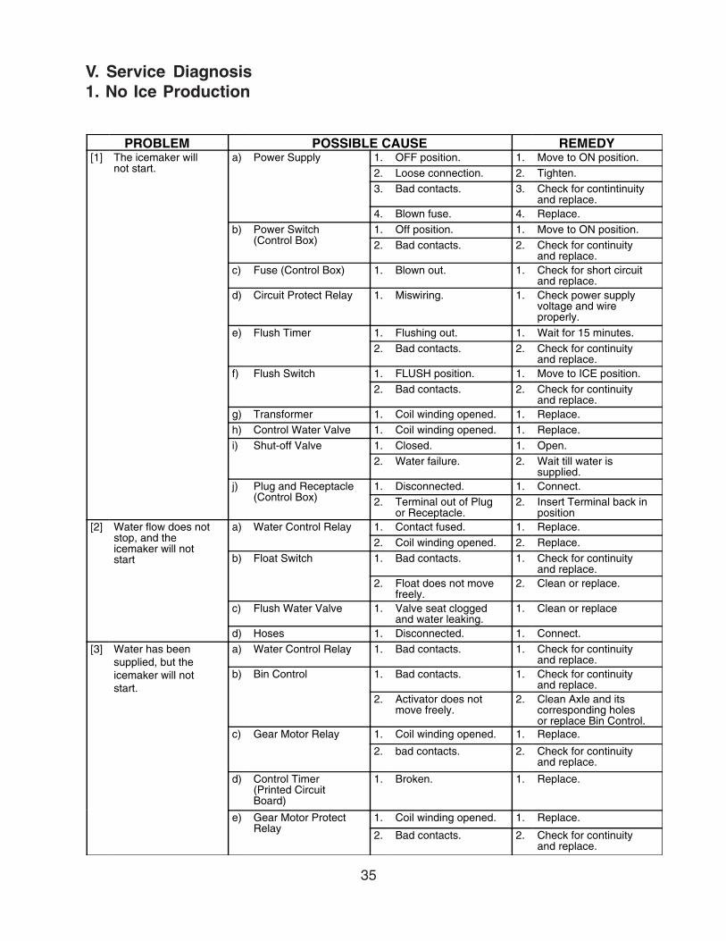
V. Service Diagnosis1. No Ice Production
PROBLEM POSSIBLE CAUSE REMEDY[1] The icemaker will
not start.a) Power Supply 1. OFF position. 1. Move to ON position.
2. Loose connection. 2. Tighten.3. Bad contacts. 3. Check for contintinuity
and replace.4. Blown fuse. 4. Replace.
b) Power Switch(Control Box)
1. Off position. 1. Move to ON position.2. Bad contacts. 2. Check for continuity
and replace.c) Fuse (Control Box) 1. Blown out. 1. Check for short circuit
and replace.d) Circuit Protect Relay 1. Miswiring. 1. Check power supply
voltage and wireproperly.
e) Flush Timer 1. Flushing out. 1. Wait for 15 minutes.2. Bad contacts. 2. Check for continuity
and replace.f) Flush Switch 1. FLUSH position. 1. Move to ICE position.
2. Bad contacts. 2. Check for continuityand replace.
g) Transformer 1. Coil winding opened. 1. Replace.h) Control Water Valve 1. Coil winding opened. 1. Replace.i) Shut-off Valve 1. Closed. 1. Open.
2. Water failure. 2. Wait till water issupplied.
j) Plug and Receptacle(Control Box)
1. Disconnected. 1. Connect.2. Terminal out of Plug
or Receptacle.2. Insert Terminal back in
position[2] Water flow does not
stop, and theicemaker will notstart
a) Water Control Relay 1. Contact fused. 1. Replace.2. Coil winding opened. 2. Replace.
b) Float Switch 1. Bad contacts. 1. Check for continuityand replace.
2. Float does not movefreely.
2. Clean or replace.
c) Flush Water Valve 1. Valve seat cloggedand water leaking.
1. Clean or replace
d) Hoses 1. Disconnected. 1. Connect.[3] Water has been
supplied, but theicemaker will notstart.
a) Water Control Relay 1. Bad contacts. 1. Check for continuityand replace.
b) Bin Control 1. Bad contacts. 1. Check for continuityand replace.
2. Activator does notmove freely.
2. Clean Axle and itscorresponding holesor replace Bin Control.
c) Gear Motor Relay 1. Coil winding opened. 1. Replace.
2. bad contacts. 2. Check for continuityand replace.
d) Control Timer(Printed CircuitBoard)
1. Broken. 1. Replace.
e) Gear Motor ProtectRelay
1. Coil winding opened. 1. Replace.
2. Bad contacts. 2. Check for continuityand replace.
36
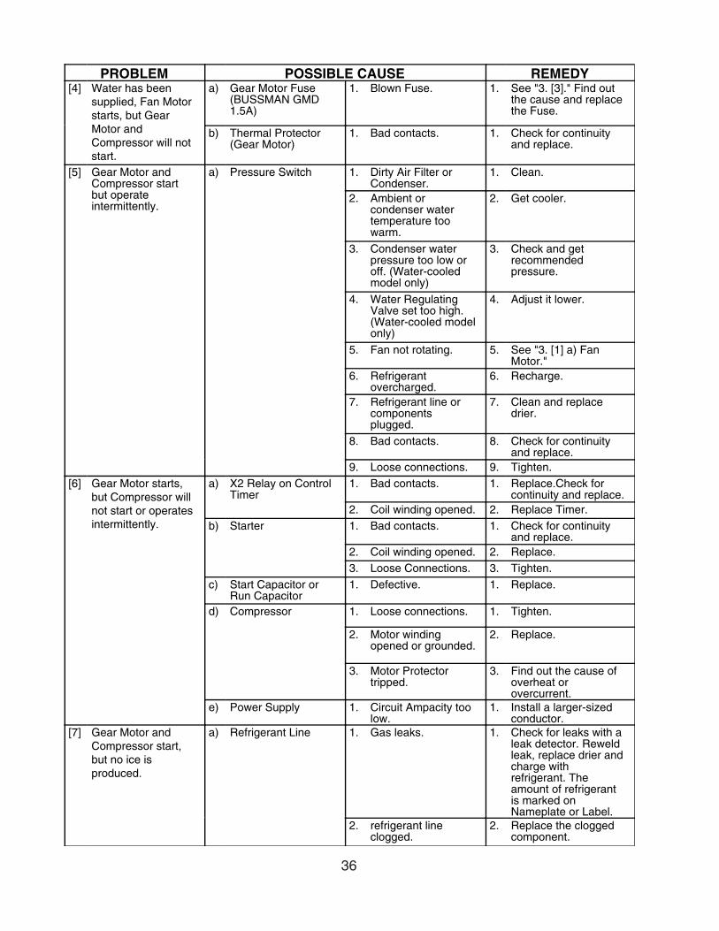
PROBLEM POSSIBLE CAUSE REMEDY[4] Water has been
supplied, Fan Motorstarts, but GearMotor andCompressor will notstart.
a) Gear Motor Fuse(BUSSMAN GMD1.5A)
1. Blown Fuse. 1. See "3. [3]." Find outthe cause and replacethe Fuse.
b) Thermal Protector(Gear Motor)
1. Bad contacts. 1. Check for continuityand replace.
[5] Gear Motor andCompressor startbut operateintermittently.
a) Pressure Switch 1. Dirty Air Filter orCondenser.
1. Clean.
2. Ambient orcondenser watertemperature toowarm.
2. Get cooler.
3. Condenser waterpressure too low oroff. (Water-cooledmodel only)
3. Check and getrecommendedpressure.
4. Water RegulatingValve set too high.(Water-cooled modelonly)
4. Adjust it lower.
5. Fan not rotating. 5. See "3. [1] a) FanMotor."
6. Refrigerantovercharged.
6. Recharge.
7. Refrigerant line orcomponentsplugged.
7. Clean and replacedrier.
8. Bad contacts. 8. Check for continuityand replace.
9. Loose connections. 9. Tighten.[6] Gear Motor starts,
but Compressor willnot start or operatesintermittently.
a) X2 Relay on ControlTimer
1. Bad contacts. 1. Replace.Check forcontinuity and replace.
2. Coil winding opened. 2. Replace Timer.b) Starter 1. Bad contacts. 1. Check for continuity
and replace.2. Coil winding opened. 2. Replace.3. Loose Connections. 3. Tighten.
c) Start Capacitor orRun Capacitor
1. Defective. 1. Replace.
d) Compressor 1. Loose connections. 1. Tighten.
2. Motor windingopened or grounded.
2. Replace.
3. Motor Protectortripped.
3. Find out the cause ofoverheat orovercurrent.
e) Power Supply 1. Circuit Ampacity toolow.
1. Install a larger-sizedconductor.
[7] Gear Motor andCompressor start,but no ice isproduced.
a) Refrigerant Line 1. Gas leaks. 1. Check for leaks with aleak detector. Reweldleak, replace drier andcharge withrefrigerant. Theamount of refrigerantis marked onNameplate or Label.
2. refrigerant lineclogged.
2. Replace the cloggedcomponent.
37
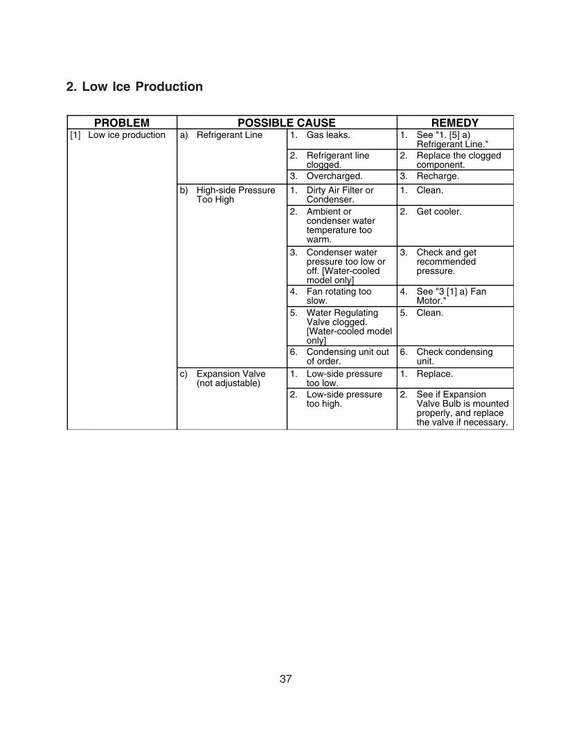
2. Low Ice Production
PROBLEM POSSIBLE CAUSE REMEDY[1] Low ice production a) Refrigerant Line 1. Gas leaks. 1. See "1. [5] a)
Refrigerant Line."2. Refrigerant line
clogged.2. Replace the clogged
component.3. Overcharged. 3. Recharge.
b) High-side PressureToo High
1. Dirty Air Filter orCondenser.
1. Clean.
2. Ambient orcondenser watertemperature toowarm.
2. Get cooler.
3. Condenser waterpressure too low oroff. [Water-cooledmodel only]
3. Check and getrecommendedpressure.
4. Fan rotating tooslow.
4. See "3 [1] a) FanMotor."
5. Water RegulatingValve clogged.[Water-cooled modelonly]
5. Clean.
6. Condensing unit outof order.
6. Check condensingunit.
c) Expansion Valve(not adjustable)
1. Low-side pressuretoo low.
1. Replace.
2. Low-side pressuretoo high.
2. See if ExpansionValve Bulb is mountedproperly, and replacethe valve if necessary.
38
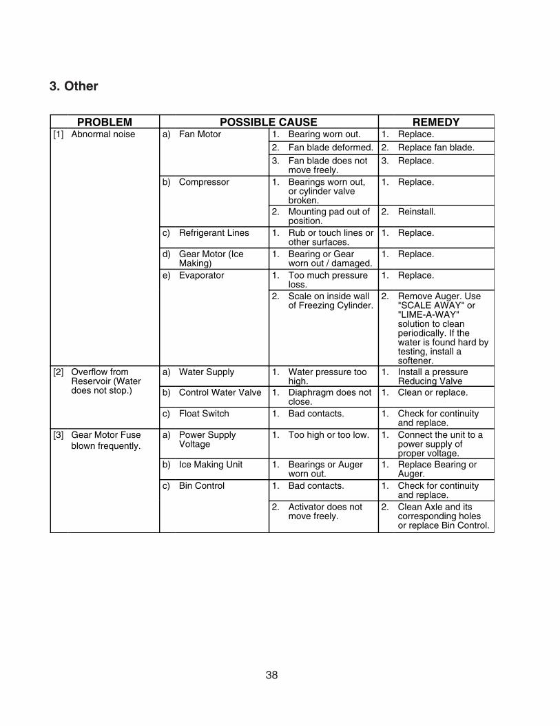
3. Other
PROBLEM POSSIBLE CAUSE REMEDY[1] Abnormal noise a) Fan Motor 1. Bearing worn out. 1. Replace.
2. Fan blade deformed. 2. Replace fan blade.3. Fan blade does not
move freely.3. Replace.
b) Compressor 1. Bearings worn out,or cylinder valvebroken.
1. Replace.
2. Mounting pad out ofposition.
2. Reinstall.
c) Refrigerant Lines 1. Rub or touch lines orother surfaces.
1. Replace.
d) Gear Motor (IceMaking)
1. Bearing or Gearworn out / damaged.
1. Replace.
e) Evaporator 1. Too much pressureloss.
1. Replace.
2. Scale on inside wallof Freezing Cylinder.
2. Remove Auger. Use"SCALE AWAY" or"LIME-A-WAY"solution to cleanperiodically. If thewater is found hard bytesting, install asoftener.
[2] Overflow fromReservoir (Waterdoes not stop.)
a) Water Supply 1. Water pressure toohigh.
1. Install a pressureReducing Valve
b) Control Water Valve 1. Diaphragm does notclose.
1. Clean or replace.
c) Float Switch 1. Bad contacts. 1. Check for continuityand replace.
[3] Gear Motor Fuseblown frequently.
a) Power SupplyVoltage
1. Too high or too low. 1. Connect the unit to apower supply ofproper voltage.
b) Ice Making Unit 1. Bearings or Augerworn out.
1. Replace Bearing orAuger.
c) Bin Control 1. Bad contacts. 1. Check for continuityand replace.
2. Activator does notmove freely.
2. Clean Axle and itscorresponding holesor replace Bin Control.
39
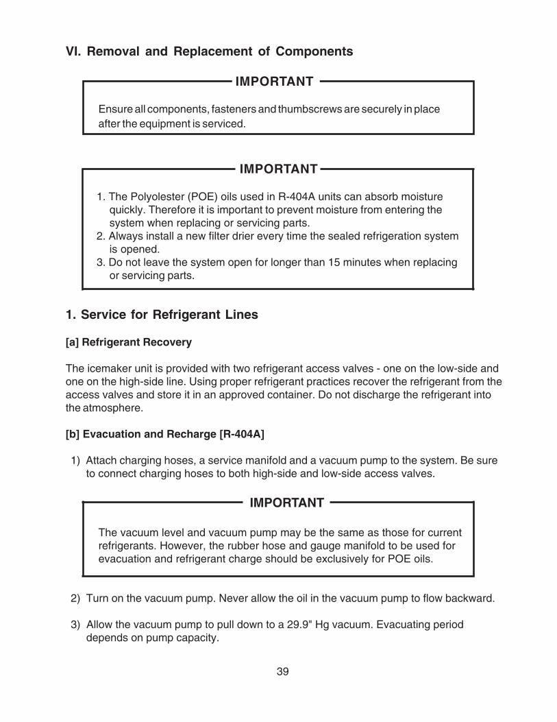
VI. Removal and Replacement of Components
1. Service for Refrigerant Lines
[a] Refrigerant Recovery
The icemaker unit is provided with two refrigerant access valves - one on the low-side andone on the high-side line. Using proper refrigerant practices recover the refrigerant from theaccess valves and store it in an approved container. Do not discharge the refrigerant intothe atmosphere.
[b] Evacuation and Recharge [R-404A]
1) Attach charging hoses, a service manifold and a vacuum pump to the system. Be sureto connect charging hoses to both high-side and low-side access valves.
IMPORTANT
The vacuum level and vacuum pump may be the same as those for currentrefrigerants. However, the rubber hose and gauge manifold to be used forevacuation and refrigerant charge should be exclusively for POE oils.
2) Turn on the vacuum pump. Never allow the oil in the vacuum pump to flow backward.
3) Allow the vacuum pump to pull down to a 29.9" Hg vacuum. Evacuating perioddepends on pump capacity.
IMPORTANT
Ensure all components, fasteners and thumbscrews are securely in placeafter the equipment is serviced.
IMPORTANT
1. The Polyolester (POE) oils used in R-404A units can absorb moisturequickly. Therefore it is important to prevent moisture from entering thesystem when replacing or servicing parts.
2. Always install a new filter drier every time the sealed refrigeration systemis opened.
3. Do not leave the system open for longer than 15 minutes when replacingor servicing parts.
40
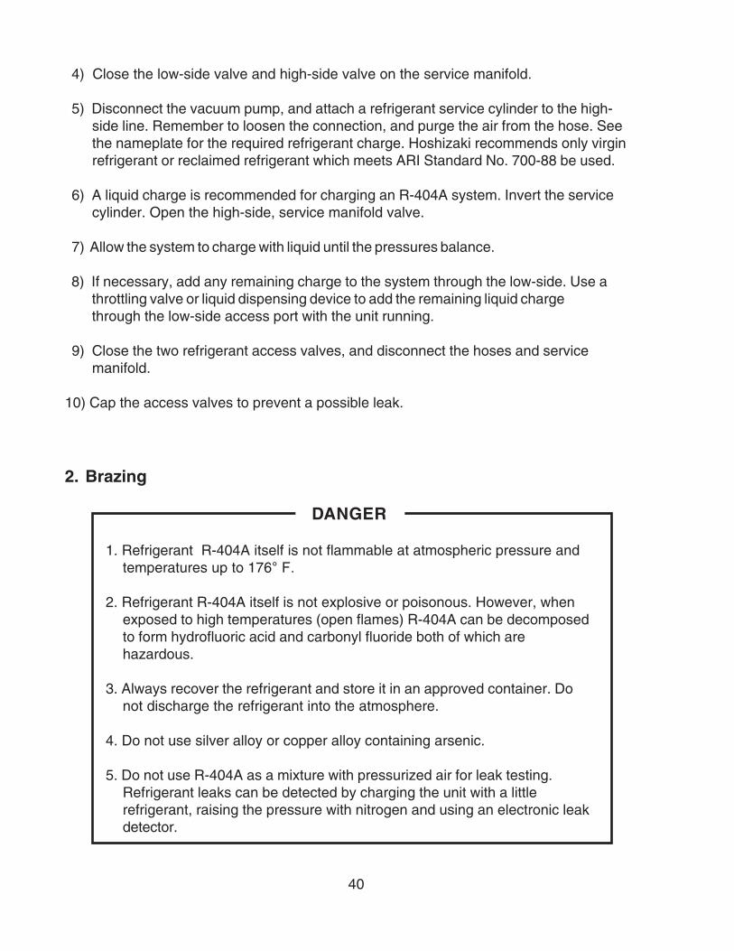
4) Close the low-side valve and high-side valve on the service manifold.
5) Disconnect the vacuum pump, and attach a refrigerant service cylinder to the high-side line. Remember to loosen the connection, and purge the air from the hose. Seethe nameplate for the required refrigerant charge. Hoshizaki recommends only virginrefrigerant or reclaimed refrigerant which meets ARI Standard No. 700-88 be used.
6) A liquid charge is recommended for charging an R-404A system. Invert the servicecylinder. Open the high-side, service manifold valve.
7) Allow the system to charge with liquid until the pressures balance.
8) If necessary, add any remaining charge to the system through the low-side. Use athrottling valve or liquid dispensing device to add the remaining liquid chargethrough the low-side access port with the unit running.
9) Close the two refrigerant access valves, and disconnect the hoses and servicemanifold.
10) Cap the access valves to prevent a possible leak.
2. Brazing
DANGER
1. Refrigerant R-404A itself is not flammable at atmospheric pressure andtemperatures up to 176° F.
2. Refrigerant R-404A itself is not explosive or poisonous. However, whenexposed to high temperatures (open flames) R-404A can be decomposedto form hydrofluoric acid and carbonyl fluoride both of which arehazardous.
3. Always recover the refrigerant and store it in an approved container. Donot discharge the refrigerant into the atmosphere.
4. Do not use silver alloy or copper alloy containing arsenic.
5. Do not use R-404A as a mixture with pressurized air for leak testing.Refrigerant leaks can be detected by charging the unit with a littlerefrigerant, raising the pressure with nitrogen and using an electronic leakdetector.
41
3. Removal and Replacement of Compressor
IMPORTANT
Always install a new drier every time the sealed refrigeration system isopened. Do not replace the drier until after all other repairs or replacementhave been made.
1) Turn off the power supply, and remove the panels.
2) Remove the terminal cover on the compressor, and disconnect the compressor wiring.
3) Recover the refrigerant and store it in an approved container, if required by an applicablelaw.
4) Remove the discharge, suction and access pipes from the compressor using brazingequipment.
WARNING
When repairing a refrigerant system, be careful not to let the burner flamecontact any electrical wires or insulation.
5) Remove the bolts and rubber grommets.
6) Slide and remove the compressor. Unpack the new compressor package. Install the newcompressor.
7) Attach the rubber grommets of the prior compressor.
8) Sandpaper the discharge, suction and access pipes.
9) Place the compressor in position, and secure it using the bolts.
10) Remove plugs from the discharge, suction and access pipes.
11) Braze the access, suction and discharge lines (Do not change this order), while purgingwith nitrogen gas flowing at the pressure of 3 - 4 PSIG.
12) Install the new drier.
13) Check for leaks using nitrogen gas (140 PSIG) and soap bubbles.
42
14) Evacuate the system, and charge it with refrigerant. For the air-cooled and water-cooledmodels, see the nameplate for the required refrigerant charge and type. For the remote air-cooled models, see the label on the control box.
15) Connect the terminals to the compressor, and replace the terminal cover in its correctposition.
16) Replace the panels in their correct position, and turn on the power supply.
4. Removal and Replacement of Drier
IMPORTANT
Always install a new drier every time the sealed refrigeration system isopened. Do not replace the drier until after all other repairs or replacementhave been made.
1) Turn off the power supply, and remove the panels.
2) Recover the refrigerant and store it in an approved container, if required by an applicablelaw.
3) Remove the drier using brazing equipment.
4) Install the new drier with the arrow on the drier in the direction of the refrigerant flow. Usenitrogen gas at the pressure of 3 - 4 PSIG when brazing the tubings.
5) Check for leaks using nitrogen gas (140 PSIG) and soap bubbles.
6) Evacuate the system, and charge it with refrigerant. For the air-cooled and water-cooledmodels, see the nameplate for the required refrigerant charge and type. For the remoteair-cooled models, see the label on the control box.
7) Replace the panels in their correct position, and turn on the power supply.

43
5. Removal and Replacement of Expansion Valve
IMPORTANT
Sometimes moisture in the refrigerant circuit exceeds the drier capacity andfreezes up at the expansion valve. Always install a new drier every time thesealed refrigeration system is opened. Do not replace the drier until after allother repairs or replacement have been made.
1) Turn off the power supply, and remove the panels.
2) Recover the refrigerant and store it in an approved container, if required by an applicablelaw.
3) Remove the expansion valve bulb at the evaporator outlet.
4) Remove the expansion valve cover, and remove the expansion valve using brazingequipment.
5) Braze the new expansion valve with nitrogen gas flowing at the pressure of 3 - 4 PSIG.
WARNING
Always protect the valve body by using a damp cloth to prevent the valve fromoverheating. Do not braze with the valve body exceeding 250°F.
6) Install the new drier.
7) Check for leaks using nitrogen gas (140 PSIG) and soap bubbles.
8) Evacuate the system. Charge it with refrigerant. For the air-cooled and water-cooledmodels, see the nameplate for the required refrigerant charge and type. For the remoteair-cooled models, see the label on the control box.
9) Attach the bulb to the suction line. Be sure to secure the bulb using a band and to insulateit.
10) Place the new set of expansion valve covers in position.
11) Replace the panels in their correct position, and turn on the power supply.

44
6. Removal and Replacement of Water Regulating Valve(water-cooled model only)
IMPORTANT
Always install a new drier every time the sealed refrigeration system isopened. Do not replace the drier until after all other repairs or replacementhave been made.
1) Turn off the power supply, remove the panels and close the water supply line shut-offvalve.
2) Recover the refrigerant and store it in an approved container.
3) Disconnect the capillary tube using brazing equipment.
4) Disconnect the flare-connections of the valve.
5) Remove the screws and the valve from the bracket.
6) Install the new valve, and braze the capillary tube.
7) Install the new drier.
8) Check for leaks using nitrogen gas (140 PSIG) and soap bubbles.
9) Connect the flare-connections.
10) Evacuate the system, and charge it with refrigerant. See the nameplate for the requiredrefrigerant charge and type.
11) Open the water supply line shut-off valve, and turn on the power supply.
12) Check for water leaks.
13) See “IV. 1. Adjustment of Water Regulating Valve.” If necessary, adjust the valve.
14) Replace the panels in their correct position.
45
7. Removal and Replacement of Evaporator Assembly
1) Turn off the power supply.
2) Remove the panels.
3) Move the flush switch to the "FLUSH" position.
4) Turn on the power supply and drain out all water from the water line.
5) Turn off the power supply.
6) Remove the strap connecting the spout to the chute assembly.
7) Remove the three thumbscrews and take off the spout from the evaporator.
Cutter
8) Remove the bolt and lift off the cutter.
9) Remove the rubber O-ring and the nylon ring at the top of the evaporator.
Extruding Head
10) Remove the four socket head cap screws and lift off the extruding head.
11) Replace the bearing inside the extruding head, if it exceeds the wear tolerance of 0.02"or is scratched.
Note: Replacing the bearing requires a bearing press adaptor. If it is not available,replace the whole extruding head.
Auger
12) Lift off the auger. If the area in contact with the bearing is worn out or the blade scratched,replace the auger.
Evaporator
Note: Skip the following steps 13) through 15) when the evaporator does not needreplacement.
46
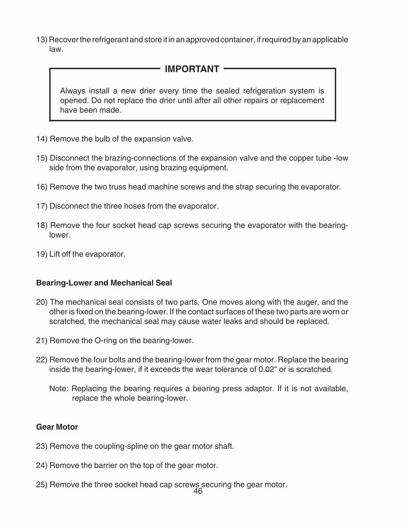
13) Recover the refrigerant and store it in an approved container, if required by an applicablelaw.
IMPORTANT
Always install a new drier every time the sealed refrigeration system isopened. Do not replace the drier until after all other repairs or replacementhave been made.
14) Remove the bulb of the expansion valve.
15) Disconnect the brazing-connections of the expansion valve and the copper tube -lowside from the evaporator, using brazing equipment.
16) Remove the two truss head machine screws and the strap securing the evaporator.
17) Disconnect the three hoses from the evaporator.
18) Remove the four socket head cap screws securing the evaporator with the bearing-lower.
19) Lift off the evaporator.
Bearing-Lower and Mechanical Seal
20) The mechanical seal consists of two parts. One moves along with the auger, and theother is fixed on the bearing-lower. If the contact surfaces of these two parts are worn orscratched, the mechanical seal may cause water leaks and should be replaced.
21) Remove the O-ring on the bearing-lower.
22) Remove the four bolts and the bearing-lower from the gear motor. Replace the bearinginside the bearing-lower, if it exceeds the wear tolerance of 0.02" or is scratched.
Note: Replacing the bearing requires a bearing press adaptor. If it is not available,replace the whole bearing-lower.
Gear Motor
23) Remove the coupling-spline on the gear motor shaft.
24) Remove the barrier on the top of the gear motor.
25) Remove the three socket head cap screws securing the gear motor.

47
26) Assemble the removed parts in the reverse order of the above procedure.
WARNING
Be careful not to scratch the surface of the O-ring, or it may cause water leaks.Handle the mechanical seal with care not to scratch nor to contaminate itscontact surface.
27) When replacing the evaporator;
(a) Braze the new evaporator with nitrogen gas flowing at the pressure of 3 - 4 PSIG.
(b) Replace the drier.
(c) Check for leaks using nitrogen gas (140 PSIG) and soap bubbles.
(d) Evacuate the system. Charge it with refrigerant. For the air-cooled and water-cooledmodels, see the nameplate for required refrigerant charge and type. For the remoteair-cooled models, see the label on the control box.
28) Move the flush switch to the "ICE" position.
29) Replace the panels in their correct position.
30) Turn on the power supply.
48
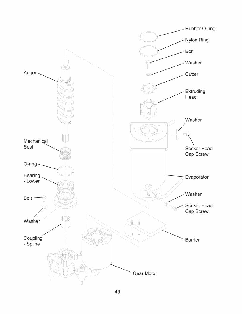
Auger
MechanicalSeal
O-ring
Bearing- Lower
Bolt
Washer
Coupling- Spline
Rubber O-ring
Nylon Ring
Bolt
Washer
Cutter
ExtrudingHead
Washer
Socket HeadCap Screw
Evaporator
Washer
Socket HeadCap Screw
Barrier
Gear Motor
49
8. Removal and Replacement of Fan Motor
1) Turn off the power supply and remove the panels.
2) Remove the wire connectors from the fan motor leads.
3) Remove the fan motor bracket and fan motor.
4) Install the new fan motor.
5) Replace the fan motor bracket and the wire connectors.
6) Replace the panels in their correct position, and turn on the power supply.
9. Removal and Replacement of Control Water Valve
1) Turn off the power supply, remove the panels and close the water supply line shut-offvalve.
2) Disconnect the terminals from the control water valve.
3) Loosen the fitting nut on the control water valve inlets, and remove the control watervalve. Do not lose the packings inside the fitting nut.
4) Remove the water supply hose from the control water valve.
5) Install the new control water valve.
6) Assemble the removed parts in the reverse order of the above procedure.
7) Open the water supply line shut-off valve.
8) Check for water leaks.
9) Replace the panels in their correct position, and turn on the power supply.
50
10. Removal and Replacement of Flush Water Valve
1) Turn off the power supply, remove the panels and close the water supply line shut-offvalve.
2) Remove the clamp and disconnect the hose from the flush water valve.
Note: Water may still remain inside the evaporator. Be sure to drain the water into thedrain pan.
3) Disconnect the terminals from the flush water valve.
4) Remove the flush water valve from the bracket.
5) Remove the drain pipe from the flush water valve.
6) Connect the drain pipe to the new flush water valve, and place the valve in position.
7) Connect the hose to the flush water valve and secure it with the clamp.
8) Pour water into the reservoir, and check for water leaks on the flush water valve.
9) Open the water supply line shut-off valve, and turn on the power supply.
10) Move the flush switch to the "ICE" position.
11) Check for water leaks.
12) Move the flush switch to the "FLUSH" position, and make sure water is flushing.
13) Move the flush switch to the "ICE" position.
14) Replace the panels in their correct position.

51
VII. Cleaning and Maintenance
IMPORTANT
Ensure all components, fasteners and thumbscrews are securely in place afterany maintenance or cleaning is done to the equipment.
1. Preparing the Icemaker for Long Storage
WARNING
When shutting off the icemaker for an extended time, drain out all water from thewater line and remove the ice from the storage bin. The storage bin should becleaned and dried. Drain the icemaker to prevent damage to the water supplyline at sub-freezing temperatures, using air or carbon dioxide. Shut off theicemaker until the proper ambient temperature is resumed.
[Air-Cooled and Remote Air-Cooled Models]
1) Run the icemaker with the water supply line shut-off valve closed.
2) Open the drain valve and blow out the water inlet line by using air pressure.
3) Turn off the power supply.
4) Remove the front panel.
5) Move the flush switch on the control box to the“FLUSH” position.
6) Turn on the power supply, and then drain out allwater from the water line.
7) Turn off the power supply.
8) Turn off the power switch on the control box.
9) Replace the front panel in its correct position.
10) Close the drain valve.
11) Remove all ice from the storage bin, and clean the bin.
Air or CO2
Drain Valve
Shut-off Valve

52
[Water-Cooled Models]
1) Turn off the power supply and wait for 3 minutes.
2) Turn on the power supply and wait for 20 seconds.
3) Close the water supply line shut-off valve.
4) Open the drain valve and quickly blow the water supply line from the drain valve to drainwater in the condenser.
5) Follow the above steps 3) through 11) in [Air-Cooled and Remote Air-Cooled Models].
2. Cleaning and Sanitizing Instructions
WARNING1. HOSHIZAKI recommends cleaning this unit at least once a year. More
frequent cleaning, however, may be required in some existing waterconditions.
2. To prevent injury to individuals and damage to the icemaker, do not useammonia type cleaners.
3. Always wear liquid-proof gloves to prevent the cleaning and sanitizingsolutions from coming into contact with skin.
[a] Cleaning Solution
Dilute 4.8 fl. oz. (142 ml) of recommended cleaner Hoshizaki “Scale Away” or“LIME-A-WAY” (Economics Laboratory, Inc.) with 0.8 gallons (3 l) of warm water. This is aminimum amount. Make more solution if necessary.
IMPORTANTFor safety and maximum effectiveness, use the solution immediately afterdilution.

53
[b] Cleaning Procedure
The cleaning process will remove lime deposits from the water system.
1) Remove the front panel and top panel, then turn off the power supply.
2) Close the water supply line shut-off valve.
3) Remove all ice from the storage bin.
4) Move the flush switch to the “FLUSH” position.
5) Turn on the power supply and drain out all water from the water line.
6) Turn off the power supply.
7) Remove the strap connecting the spout to the chute assembly.
8) Remove the thumbscrews securing the spout and lift it off.
9) Pour the cleaning solution over the extruding head until the evaporator assembly and thereservoir are filled and the solution starts to overflow into the drain pan.Note: If there is excess scale on the extruding head, fill the evaporator assembly and
reservoir as described above, then use a clamp on the reservoir hose between thereservoir and evaporator assembly to block flow. Pour additional cleaning fluidover the extruding head until the evaporator assembly is completely full.
10) Replace the spout and strap in their correct positions.
11) Allow the icemaker to sit for about 10 minutes before operation. If you placed a clamp onthe reservoir hose in step 9, remove it before operation.
12) Move the flush switch to the “ICE” position, then turn on the power supply. Replace thetop panel and front panel in their correct positions. Make ice using the solution until theicemaker stops making ice.
13) Remove the front panel.
14) Move the flush switch to the “FLUSH” position to drain the remainder of the solution.
15) After the solution is drained, move the flush switch to the “ICE” position.
16) Replace the front panel in its correct position.
17) Open the water supply line shut-off valve and supply water to the reservoir.
18) When the gear motor starts, remove the front panel and turn off the power supply.
19) Drain out all water from the water line. See 4) through 6).

54
[c] Sanitizing Solution
Dilute 2.5 fl. oz. (74 ml or 5 tbs) of IMS-II Sanitizer or a 5.25% sodium hypochlorite solution(chlorine bleach) with 5 gallons (19 l) of warm water.
IMPORTANTFor safety and maximum effectiveness, use the solution immediately afterdilution.
[d] Sanitizing Procedure - Initial
The sanitizing process will sanitize the icemaker.
1) Close the water supply line shut-off valve.
2) Remove the strap connecting the spout to the chute assembly.
3) Remove the thumbscrews securing the spout and lift it off. Remove the rubber O-ring andnylon O-ring at the top of the cylinder and also remove the packing between the spoutand the chute.
4) Pour the sanitizing solution over the extruding head until the evaporator assembly andthe reservoir are filled and the solution starts to overflow into the drain pan.
5) Remove the two thumbscrews securing the proximity switch to the chute assembly.
6) Remove the chute assembly from the icemaker.
7) Remove the packing at the bottom of the ice chute.
8) Remove the three ties and the chute insulation.
9) Remove the six wing nuts and two baffles.
10) Remove the two thumbscrews, the plate and the packing from the top of the ice chute,then remove the bin control assembly by sliding it slightly toward the chute opening andlifting it off.
11) Disassemble the bin control assembly by removing the two snap pins, shaft andactuator.
12) Soak the removed parts in .25 gallons (1 l) of sanitizing solution for 10 minutes thenwipe them down.
13) Rinse the parts thoroughly.IMPORTANT
If the solution is left on these parts, they will rust.
55
14) Replace all parts in their correct positions.
IMPORTANTWhen installing the baffles, make sure that the bent surface (the one without thestuds) faces the actuator so that the bent surface can guide the ice to the centerof the actuator.
15) Move the flush switch to the “ICE” position, then turn on the power supply. Replace thetop panel and front panel in their correct positions. Make ice using the solution until theicemaker stops making ice.
[e] Sanitizing Procedure - Final
1) Remove the front panel and top panel, then turn off the power supply.
2) Move the flush switch to the “FLUSH” position.
3) Turn on the power supply and drain out all water from the water line.
4) Turn off the power supply.
5) Remove the strap connecting the spout to the chute assembly.
6) Remove the thumbscrews securing the spout and lift it off.
7) Pour the sanitizing solution over the extruding head until the evaporator assembly andthe reservoir are filled and the solution starts to overflow into the drain pan.
8) Replace the spout and strap in their correct positions.
9) Allow the icemaker to sit for about 10 minutes before operation.
10) Move the flush switch to the “ICE” position, then turn on the power supply. Replace thetop panel and front panel in their correct positions. Make ice using the solution until theicemaker stops making ice.
11) Remove the front panel.
12) Move the flush switch to the “FLUSH” position to drain the remainder of the solution.
13) After the solution is drained, move the flush switch to the “ICE” position.
14) Replace the front panel in its correct position.
15) Open the water supply line shut-off valve and supply water to the reservoir.
56
16) When the gear motor starts, remove the front panel and turn off the power supply.
17) Drain out all water from the water line. See 2) and 3).
18) Move the flush switch to the “ICE” position and run the icemaker.
19) Turn off the power supply after 30 minutes.
20) Pour warm water into the storage bin to melt all ice, and then clean the bin liner with thesolution.
21) Flush out any solution from the storage bin.
22) Turn on the power supply and start the automatic icemaking process.
IMPORTANT1. After cleaning, do not use ice made from the sanitizing solution. Be careful
not to leave any solution in the storage bin.2. Follow carefully any instructions provided with the bottles of cleaning or
sanitizing solution.3. Never run the icemaker when the reservoir is empty.
57
3. Maintenance
IMPORTANT
1. This icemaker must be maintained individually, referring to the instructionmanual and labels provided with the icemaker.
2. To have the optimum performance of this icemaker, the followingconsumable parts need periodical inspection, maintenance andreplacement:
Extruding HeadHousingGear MotorAugerMechanical Seal
These parts should be inspected at least once a year or every 10,000 hoursof operation. Their service life, however, depends on water quality andenvironment. More frequent inspection and maintenance are recommended.
Consult with your local distributor about inspection and maintenanceservice. To obtain the name and phone number of your local distributor, callHoshizaki Technical Support at 1-800-233-1940.
1) Stainless Steel Exterior
To prevent corrosion, wipe the exterior occasionally with a clean and soft cloth. Usea damp cloth containing a neutral cleaner to wipe off oil or dirt build up.
2) Storage Bin and Scoop
* Wash your hands before removing ice. Use the plastic scoop provided (binaccessory).
* The storage bin is for ice use only. Do not store anything else in the bin.
* Keep the scoop clean. Clean using a neutral cleaner and rinse thoroughly.
* Clean the bin liner using a neutral cleaner. Rinse thoroughly after cleaning.
58
3) Air Filter (air-cooled model only)
A plastic mesh air filter removes dirt or dust from the air, and keeps the condenserfrom getting clogged. As the filter gets clogged, the icemaker’s performance will bereduced. Check the filter at least twice a month. When clogged, use warm water anda neutral cleaner to wash the filter.
4) Condenser (except water-cooled model)
Check the condenser once a year, and clean if required by using a brush or vacuumcleaner. More frequent cleaning may be required depending on the location of theicemaker.