f 7/7, - nasa · tref= tk + _i (t --tk) yfr = yfs 1 in the limitingcases of the droplet impingement...
TRANSCRIPT

r
f
7/7, ,_
EFFECTS OF TURBULENCE MIXING,
VARIABLE PROPERTIES, AND VAPORIZATION
ON SPRAY DROPLET COMBUSTION
Y.M. Kim and T.J. Chung
Department of Mechanical EngineeringThe University of Alabama in Huntsville
Huntsville, Alabama, USA
Point of Contact
Professor T.J. ChungDepartment of Mechanical Engineering
The University of Alabama in HuntsvilleHuntsville, AL 35899
Telephone: (205) 895---6394
(NASA-CR-186463)
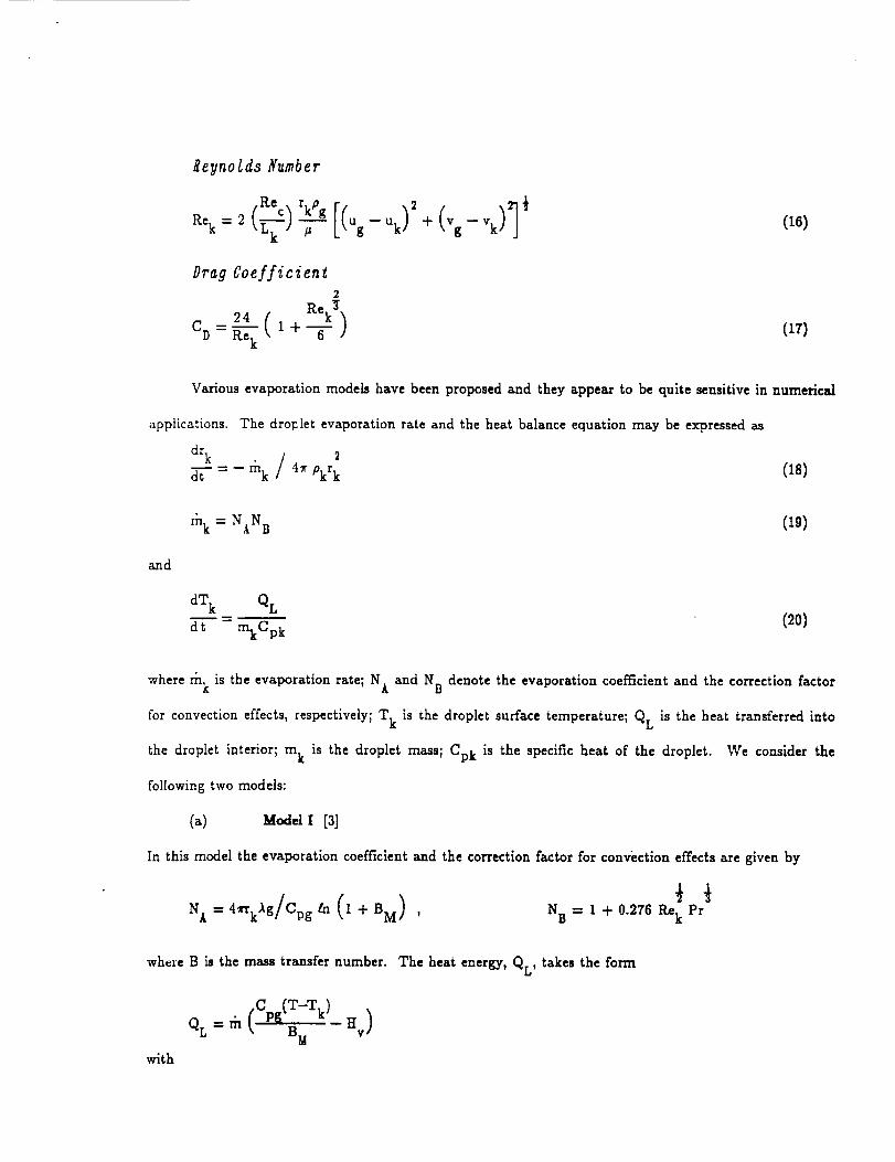
MIXING v VARIA_LEVAPORIZATION ON(Alabama Univ.)
6FFECTS OF TURBULENCE
PROPERTIES, ANDSPRAY DROPLET CqMBUSTION
22 p CSCL 07D
G3/25
N90-1932o
Unclas0271795
https://ntrs.nasa.gov/search.jsp?R=19900010010 2019-04-29T20:59:39+00:00Z

EFFECTS OF TURBULENCE MIXING, VARIABLE PROPERTIES, ANDVAPORIZATION ON SPRAY DROPLET COMBUSTION
Y.M. Kim and T.J. Chung
ABSTRACT
\ Combustion of liquid fuels in the form of spray droplets is simulated numerically in this paper.
Variou_ vaporization models are examined as to their performance in finite element calculations involving
turbulent flow field. Thc Eulerian_oordinate for the gas and Lagrangian _oordinate for the liquid spray r"
droplets a_coupled through source terms being updated in the equations of continuity, momentum, and\
energy. The _ and modified eddy breakup models are used for simulating turbulent spray combustion
flow field. Numerical results for the droplet trajectories, droplet heating, recirculation characteristics, and
effects of cvapolation models are evaluated. It is also shown that the finite element method is
advantageous in dealing with complex geometries, complex boundary conditions, adaptive unstructured
grids ....
1. IwrI_ODUCTION
One of the most critical aspects in spray combustion is an adequate vaporization model in which
the effect of neighboring droplets on the rates of heat and mass transport and vaporization for any given
droplet can be properly taken into account [1,2]. This is particularly important if the ambient gas
temperature is high so that droplet life times and droplet heating times are of the same order of
magnitude. Difficulties arise also in turbulent flow where the k--e model found satisfactory in
nonreacting gas media may not be applicable in reacting spray combustion. A similar question is raised
a.s to the adequacy of modified eddy breakup model to determine the mixing rates of reactants. The
main issue in this paper, however, is not the development of such models, but rather the implementation
of computational techniques for the turbulent spray combustion using the currentlyavailablephysical
models. Three vaporization models [2,3] are examined.
We present finite element calculations [5] of turbulent spray combustion [6] using the Eulerian
Coordinate for the gas and Lagrangian Coordinate for the liquid spray droplets, the k--e turbulence
model, the eddy breakup model for predicting the mixing rates of the reactants. In turbulent reacting
flows in the Eulerian coordinates, the velocity and pressure fields are strongly coupled with various source
terms including turbulence, gas/liquid_phase interaction, and chemical reaction rates.
* Research Associate
** Professor

To preventthespuriouspressuremodes, the mixed interpolationfiniteelement method isused. Such
coupled solution eliminatesthe need for transformation of the continuity equation into a pressure or
pressure correctionequation in the sequentialmethod. The coupled method used here is relatively
insensitiveto Reynolds numbers and grid aspect ratio. Other transport equations are solved sequentially.
The solutionprocedure for gas---phaseequations issimilarto the single--phaseturbulent reactingflows.
The ordinary differentialequations governing the droplet field in the Lagrangian coordinates are
integrated using an explicitsecond-order Runge--Kutta method. The gas---phasepropertiesat the
characteristiclocation are calculatedby linearinterpolationof the four isoparametric finiteelement
Eulerian nodal values in the computational clement containing the droplet. The characteristicsource
terms at the Eulerian grid isevaluated by superimposing the nonlinear source term of each characteristic
to the four surrounding grid pointsusing the volume--weighted linearinterpolation.
Applicationsincludecalculationsof droplettrajectoriesas well as the complete flow fieldvariables
in a centerbody combustor. It isshown that the present i'miteelement model predictsthe qualitative
features of the turbulent spray combustion satisfactorily,pending veri/lcationby experimental
measurements. The computational resultsshow that the variationsof thermophysical propertiesand the
dropletheatingmodel have the significanteffectson the droplethistoryand the gas--phaseflowfieldnear
the injectionregion.
2. GAS FIELD EQUATIONS IN EULERIAN COORDINATES
The governing equations in Eulerian coordinates include equations of continuity, momentum,
fractions,turbulent kineticenergy,dissipation,and concentrationfluctuations.
Continuity
Op O 1 0 1 1
0"T+_(pu) +_-_(ypv)=_c )I _kk kknrh
with nk = no. of droplets,and m k - droplet vaporizationrate.
mean quantities.
m_
(1)
Here all variables are time-averagod

Axial Momentum
Opu + O [PU' -- _e -_] + _-_[YPuv -- Yl_eOt --
1 1 4x 3 du k"
+ _c p" _kk (nk _kuk --_- ok rknk d-'t--)
_adial iomentum
0 2
2_eV +__!_1 1 / • 4_ 3 dv k"nkmkVk--_ Re c _ --3"Pkrknkd-t-')
Mass Fraction of Fuel
OPYf 0 _ iO [ypvYf--yFeO_]--_-+-_[puYf reO_] +y_
o_+_ _ ('"o_)
10 N=-_+_
1 i
=__f_+_ r__ °2'_
#ass Fraction of Oxidizer
0 OYo 1 0OPY°ott""_[PUYo--I'e O--x"]+_[YPVYo--YreO_] = --vwoRfu
(2)
(_)
(4)
(5)
Energy
Ot +'_ puh--I' -- + ypvh--yI' e = (--
. I 0 I IOcp.
-°(rJ o_) -7_(YrJ _--)+ _.¢ _ Vk"k_(h.-- %)
turbulent Kinetic Energy
a-T-+ _ p_k- r -- + _ _ yp_k-- yI" = _tO -- p,
?urbulent Energy Dissipation
0_+_ pu,-r + 1 o,, 7 _ Y_' - yr = c_c_GkP--C_,oFlk
Dc
--i + wfQRfu + pT¢
(6)
(_,3
(8)

Concentration Fluctuation
where
0t "_x pug -- F e
r /c #l
Lk - ' #e = _ + #t r _' •
r / c
k,o
oqY" 2
cgl#eF( f50Y 2 e
2_l #t k
+_' #t =_#P7-°'_lRec _t
(9)
°: _L,o.,+(_-)'+(_) +(_+_,,
with _¢ representing Schmidt or Prandtl number for the dependent variable 4. Note also that the
gas--phase equations are non--dimensionalized using the inflow conditions of the combustor under study,
leading to Rec, the characteristicReynolds number, Me, the characteristicMach number, and Lk, the
ratioof the gas--phaselengthscaleto the initialdropletradiusof the k th group.
The reaction rate Rfu isdetermined from eitherthe mixing ratesof the reactants or the chemical
reaction,whichever slower. The mixing ratesof the reactantsare obtained by the eddy breakup reaction
model [7]assuming that the ga_ iscomposed of alternatingfragments of unburned fueland almost fully
burned gas. The eddy breakup reactionrate isassumed to depend on the rate _ at which the fragments
of unburned fuel are broken into smaller fragments by the action of turbulence, and is taken to be
proportional to the decay of turbulence energy e/k.
The reaction rate may also be controlled by chemical kinetics when the mixing to the reactants is rapid
[8]. Thus the reaction rate is expressed an
Rfu = min
( p Yf)a( p Yo)b
,w-T,,W7o,C
It
_ _ (_-)(10)
The specific heat of the mixture is given by
Cp = Z YiCp,i(T)i
(11)

Here by assuming equal binary diffusion coefficients for all the species and by knowing the mau fractions
of fuel and oxidizerand the stoichiometricrelationshipof the given hydrocarbon--airmixture, the mare
fractionsof the remaining species(02, N2, CO2, and H20) can be determined. The variationof the
specificheat,with temperature may be writtenas [9,i0].
R 2Cp,i= _. (CIi + C2iT + C3iT
1
3 ,)+ C4iT CsiT
The densitydistributioninthe gas phase iscalculatedfrom
p = P/RT _ Yi/Wi
The model constants used in the above equationsare as follows:C = 1.44 ,Cl 2
gk=l.0,g =1.217,_ =0.9,# =0.9,gh=0.9,C =2.8,C =2.0.e Y g g2 g2
3. LIQUID SPRAY DROPLET FIELD EQUATIONS IN LAGRANGIA/_ COORDINATES
The liquid--phaseequations are based on the Lagrangian formulation of the droplet trajectory,transient
heating, and vaporization. The effectiveconductivity model used in the present study assumes the
quasi-steadinessin the gas film.The instantaneous vaporizationrate of the dropletiscontrolledby the
transient process of heating of the liquid inside the droplet. In the limiting cases of the droplet
impingement on the chamber walls the droplets undergo instantaneous vaporization. The governing
equations for the liquid--phaseare as follows:
ge loci ties
dxk dYk
d-'t'-= Uk' d"_""-Vk (13)
Rate of Change of Velocities
d-_ = RecPk 16 r]_
.r .
)dt = _,RecPk/ I-'6 r_
£eynoldsNumber
-Re c- rkPg
Drag Coefficien_
2
(16)
(17)
Various evaporation models have been proposed and they appear to be quite sensitive in numerical
applications. The drol=let evaporation rate and the heat balance equation may be expressed as
drk 2
dt - rhk / 4_ Pkrk (18)
and
rnk = NAN B (19)
dTk QL
dt - mkCpk(20)
where rn k is the evaporation rate; N A and N B denote the evaporation coefficient and the correction factor
for convection effects, respectively; T k is the droplet surface temperature; QL is the heat transferred into
the droplet interior; m k is the droplet mass; Cpk is the specific heat of the droplet. We consider the
following two models:
(a) Model I [3]
In thismodel the evaporation coefficientand the correctionfactorfor convection effectsare given by
I
where B is the mass transfer number. The heat energy, QL' takes the form
QL rn (Cp_(T-Tk) Hv)---- _. B M --
with

HereYfsandPfs are the mass fraction and the fuel vapor pressure at the droplet surface, respectively; P)
the ambient pressure, is the sum of the fuel vapor pressure and the air partial pressure at the droplet
surface; Wa and Wf are the molecular weights of fuel and air, respectively. For any given value of
surface temperature, the vapor pressure is readily estimated from modified Clansius--Clapeyron equation.
Values of a , a ,and a are found in [3,4].Ifthe heat transferto the droplet interiorisneglected,thenl 2 3
we set Hv,ef f - Hr. Also, to keep the heat transfer rate of vaporization (r_ Hv,eff ) positive, it is
necessary to maintain Yf_ - 0.
(b) Model II [3]
Model IIisthe same as Model I except forthe effectivelatentheat of vaporization. Considering the heat
transferredin the dropletinterior(QL) ,the effectivelatentheat of vaporizationcan be obtained from
B t
Hv,ef f = H v + QL/rn = _ ttvm
with
B t =
where B t
Cpg (T -- Tk)
HV
isthe heat transfernumber
(c) Model Ill [41
This model includes the effects of variable thermophysical properties, non--unitary Lewis number in the
gas film, the effect of the Stefan flow on heat and mass transfer between the droplet and the gas, and the "
effectof internalcirculationand transientliquid heating. Thus, the evaporation coefficientand the
correctionfactorfor convectioneffectsare as follows:
N t =4. rkpgDgln (1 + BM) , N B :1 +
with

0.7tn(1+B) (film thickness correction) (21)F(B) = (I+B) B
for Rek < 1
for 1 < Re k <_.400
(22)
(23)
The heat energy takes the form
where
[%_(T_.-Tk 1QL = rn [ BT --H vJ
( )¢ i, #=BT = I + B M --
Cpf Sh 1
Cpg Nu Le
Le = Ag/pg Dg Cpg ,
,,,:,:, + --1)/ F(B T )
1
.Uo=,+(,+ ,,,)',(,,,,,)The average properties of air--vapor mixture may be determined at the following reference
temperatures and compositions [11]:
I (T --Tk) Yfr = YfsTref = T k + _1
In the limiting cases of the droplet impingement on the chamber walls, the droplets undergo
instantaneous vaporization. A similartreatment of the dropletisconsidered when approximately 97% of
the mass of the droplets isvaporized. In case of the droplet passage through the plane of symmetry,
another dropletwith similarinstantaneouspropertiesand physical dimensions, but with the mirror image
velocityvectorisinjectedinto the flow field.
4. COUPLING OF LIQUID AND GAS PHASES
The liquid--phaseequations for spray droplets are advanced in time by an explicitsecond--order
Runge---Kattamethod using time stepsmuch smallerthan the gas-phase equations. Based on the known

gas--phase properties, the liquid--phase equations are first advanced in time from the nth time level to
the (n+l)th time level corresponding to the gas--phase time step Atg as follows:
(1) Interpolate linearly the gas--phase properties from the fixed Eulerian
(2)
(3)
(4)
locationsto the characteristiclocation.
Integratethe liquid-phaseequations over a time step,At I.
Redistribute the source terms evaluated at the characteristiclocation among the
Eulerian nodes surrounding the characteristic.
Steps (I) -- (3) are repeated untilthe llquid--phaseequations are advanced over a time
step,Atg.
Solve the gas-phase equationsusing the time implicitscheme.
Repeat steps (i)--(5) untilthe iterationconverges beforeadvancing to the next step.
(s)
(8)
The injectedspray and the dropletflow isassumed to be conicalsuch that
uk=uk, ocost_ , vk--vk, osin 0
where 0 isthe half---coneangle. The mass flow rate of the fuelis determined from the stoichiometric
conditionsand the injectiontime intervalfor a new characteristicto appear isbased on the Euhrian
mesh sizeAx and injectionvelocityUk,° ofthe droplet.
Axdt-
LIR _O
Thus the number of dropletsin each characteristicisgiven by
s M f,kdt
nk = Lk -_r Pk
where Mf,k isthe mass flow rateisrelatedto
Mf = Y, Mf, k = 0.21 _ ma Wf/_Wo
Once the droplets are injected its subsequent behavior is determined by the governing equations.
5. BOUNDARY CONDITIONS
Steep gradients and a relatively low level of turbulence prevail along the wall. To account for rapid
changes in velocity"profilecloseto the wall,the so-called wall function method isemployed [12].In the
context offiniteelements, we assume that the shear stressisconstant up to a distance_ from the wall

suchthat
y --W
with
U 4.
_ for6 <11.81
p ku C 4 k½4.
U
+ for 6 _> 11.8InZ6
, p6 c ¼ k½6 - u
#
Once the near--wallvaluesof the shear stressesare evaluated,we calculatethe near--wallvaluesof
the k and e as follows:
l 'w/pI l wlp13/2k- _--
c _ ' _6#
The near--wall heat flux is determined by
Cp (T--Tw) +
# for 6+ < 11.6
Pr 6
[i _] for6 > 11.6Pr t -- L_ _n (E64.) + pr tj -
where the function P(pr) is of the form.
P---_-" 9"24 [(Pr _3/4 ][ /--0"007 P-_rt) ]pr t L_V_.d -- 1 1 + 0.28 exp Pr
Here r and ctw are specified as Neumann boundary conditions in the momentum and energy equations.W
6. APPLICATIONS
Numerical resultsinclude comparisons of three differentmodels of vaporization models applied to a
typicalturbulent spray combustion. Figures l.a through l.d show the vaporization characteristicsof
O
n---decanedroplets of initialradius rk,° = 50 /an and Tk,° = 300 K which are injected into the airO
stream at P_ = 10arm, T_ = 1500 K, and _Uo = u -- U k = 10m/s. The temporal variationof the
non-dimensional droplet surface area, surface temperature, vaporization rate (rh/mo) , effectiVeheat
transfer rate of evaporation (rhHv,eff) , are shown in Figures l.a, l.b, l.c, and l.d, respectively. Here m °
is the initial droplet mass.
The numerical results indicate that the droplet heating process takes a considerable part of the droplet
lifetime. Note here that the vaporisation histories of Model 1 are the same as those of Model 2 except
when the effective vaporization heat transfer rate is used for Model 2. The transient heating period of
Model 1 or Model 2 is much shorter than Model 3. At the final stage, the droplet surface temperature
for both models approaches an equilibrium value which is the wet--bulb temperature. Model 1 or
Model 2 leads to a higher wet-bulb temperature than Model 3. Since the transfer number of Model 3 is
based on the effective latent heat vaporisation, Model 3 has a slower vaporization than Model 1 or
Model 2 in the initial heating period. Figure l.d shows the temporal variations in the effective heat
transfer vaporization (rhHv,eff). Models 2 and 3 have the large heat transfer rate in the early
evaporation period which is controlledby the effectivelatent heat vaporization. However, the heat
transferrate ofvaporizationforModel I iscontrolledby the vaporizationrate because the effectivelatent
heat in Model i isobtained by neglectingthe heat transferto the droplet interior.Since Model 2 has a
fastervaporizationthan Model 3 in the droplet heating period,Model 2 shows a largereffectiveheat
transferratethan Model 3.
Figures 2.a through 2.d show the vaporizationcharacteristicsof n--decane dropletsin the alr--fuel
mixture medium with Yfo0 -- 0.4. All other conditions are the same as the previous example. This
situationisfrequently encountered in the actual spray combusting flows. The vaporizationhistoryof
Model I is the same as the previous case because this model does not account for the effectof the
ambient fuelvapor. The introductionof any cold dropletinto a surrounding of itsown vapor resultsin
vapor condensation on the dropletsurface. In the condensation period,the ma_ transfernumber, BM,
becomes negative if the mass fraction of fuel at the interface is less than the mass fraction of fuel at the
ambient. As a result, the droplet undergoes the increase in radius. It can be seen that the droplets with :.
its ambient fuel vapor evaporates much faster than the previous case without the ambient fuel vapor. In
fuel vapor environment, the droplet Reynolds number increases due to variable property effects related to
the liquid dynamic viscosity. The effect of an increase in Reynolds number on heat and mass transfer
obviously causes the Nusselt number and Sherwood number to increase. Therefore, the higher droplet
Reynolds number results in increase of the vaporization rate. During the condensation period, Model 2
yields a larger condensation rate than Model 3. Shortly after the condensation period, Model 2 exhibits a
faster vaporization than Model 3. However, at the final stage of vaporization, Model 2 shows a slower
evaporation than Model 3. Model 2 yields a larger effective heat transfer rate than Model 3 during the
entire vaporization period except for the condensation period and the final stage.
The next example is for the computation of the spray combusting flows using three vaporization
models with the geometry of a centerbody combustor shown in Figure 3 and the initialand boundary
conditionssummarized in Table I. The dimensions of the combustor are the same as those used in Raju
and Sirignano [13]. However, the present study uses the variable thermophysical properties. The
injectedspray isassumed to comprise four conicM streams and hMf---anglesof the corresponding stremms
at _ -- 5, 15, 25, and 35 degrees. The computations are performed for three vaporization model=
discussedearlier.In the limitingcases of the droplet impingement on the chamber walls,the dropletl
undergo instantaneous vaporization. Similar treatment of the droplet is considered when 97% of the
mass of the dropletisvaporized. In case of the dropletpassage through the plane of symmetry, another
dropletwith similarinstantaneouspropertiesand physicaldimensions but with the mirror image velocity
vector isinjectedinto the flow_eld. The time steps for the steady stateare:At.. = 1.6 m/s, At - 1.6mj g
ms, and _tl,m = 0.04ms.
Figures 4.a through 4.c show droplettrajectoriesand vaporizationprocessesfor three vaporization
models. The four droplet groups can be identifiedby the volume of the droplet and the characteristic
location. Itisseen that the droplet motion isinitiallygoverned by the droplet inertiaforce before the
drag force causes the droplets to decelerateand the droplet path is eventually determined by the
gas--phase flow field. Most of the vaporizationoccurs within the recirculationzone because the smaller
dropletsare unable to penetrate downstream. Because of the strong negative radialgas--phase velocity
fieldnear the injector,the droplet trajectoriesare significantlyaffectedby the gas---phasevelocityfield
especially for the dropletcharacteristicwith the lowest injectionangle, 0 = 5 degrees.

The strong negative radialgas--phasevelocityfieldin the injectorregionresultsfrom the largedrag force
term interactingwith the source terms of radialmomentum equation. Model i has a fasterevaporation
rate than two other models. Slightdifferencesbetween Model 2 and Model 3 exist in the droplet
trajectoriescorresponding to the finalstageof vaporization.
Velocity vectorsfor three vaporizationmodels are shown in 5.a through 5.c. The velocityfieldfor
three models has the similarsecondary recirculationzone. This isdue to the gas-droplet interactionin
recirculationzone having the high vaporizationrate. Slightdifferencesamong three models existsin the
downstream sideof the recirculationregion.
Figure 6 shows contours of temperature for three vaporizationmodels. The temperature difference
between two adjacent linesisabout 150°K. The maximum and minimum temperatures of the gas-field
are about 2800°K and 700°K. The low temperature near the injectorresultsfrom the cooling effectof
the vaporizationprocess. This regionisalsocharacterizedby largetemperature gradients.
Radial profilesof temperature for three vaporizationmodels are presented in Figure 7. Since the
effectivelatentheat for Model I predictsa much higher temperature than the other two models in the
fuel--richsideof threeaxiallocations,Model 1 exhibitsthe highesttemperature, followed by Model 3 and
Model 2. Temperature distributionsin the fuel---richregionmainly depend on the effectiveheat transfer
rateof vaporization(rn Hv,eff).
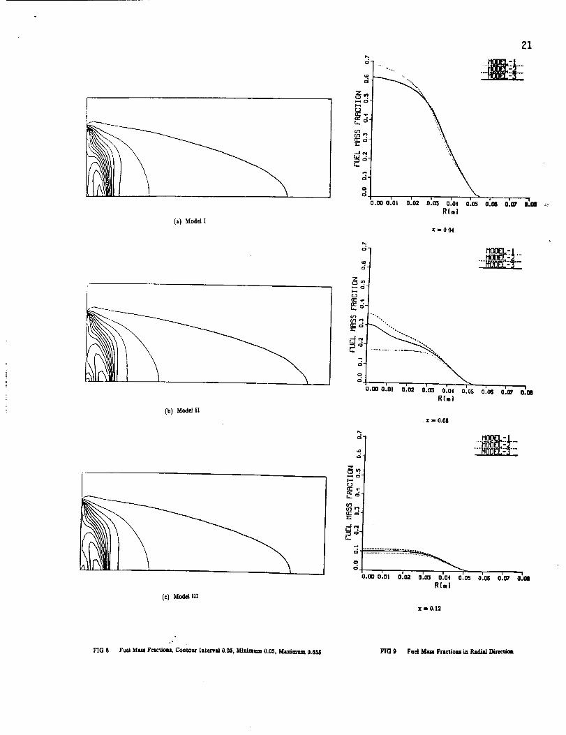
Figure 8 shows contours of the fuelmass fractionfor three vaporizationmodels. The values of the
contour linesvary from 0.005 to 0.655 with the mass fractiondifferenceof 0.05. The large concentration
offuelvapor in the recirculationregionisdue to insufficientmixing of fueland air.
Finally,radial profilesof the fuel m_ fraction for three vaporization models are shown in
Figure 9. Since Model I predicts a fasterevaporation due to a higher temperature near the injector
region (x - 0.004m), Model I yieldsa much largerfuel mass fractionthan the other two models. At
some distance from the injector(x = 0.08m,0.12rn),Model I predicts the lowest mass fuel fraction
resultingfrom the uhortestdropletlifetimewith the high gas--temperature environment. Model 2 shows.r
a largerfuel mass fractionthan Model 3 at some distance downstream (x = 0.08m, 0.12m), because
Model 2 yieldsa fasterevaporationrelatedto the complex effectsof variableproperties.

7. CONCLUSIONS
Numerical analysis using the finite element Eulerian--Lagrangian approach for various vaporization
models for turbulent spray combustion has been shown to be effective. The following comments are
offered:
(1) Variations of the thermophysical properties and the droplet vaporization models are sensitive to the
droplet histories and the gas--phase flowfield especially close to the fuel injector region.
(2) Droplet trajectories are greatly influenced by the choice of existing vaporization models which
determine the vaporization rate and the effective latent heat of vaporization.
!3) Model 1 has a faster vaporization rate, leading to the droplet trajectories affected more rapidly by the
gas--phase flowfield than Models 2 and 3.
(4) The gas--phase velocity field for all vaporization models appears to have a similar secondary
recirculation zone. The gas-droplet interactions play a negligible role for the formation of secondary
recirculation zone.
(5) Temperature distributions near the fuel--rich injector are significantly affected by the transient
droplet heating in terms of the effective latent heat of vaporization. Model 1 predicts the highest
temperature distributions, followed by Model 3 and Model 2.
(6) Close to the fuel injector, Model 1 yields a much larger fuel mass fraction than the other two models,
reversing the trend downstream because of the shortest droplet lifetime with the higher gas---phase
temperature distribution.
(7) Model 2 predicts a slightly larger fuel mass fraction than Model 3 downstream, due to a faster
evaporation rate.
(8) In terms of computational strategies, the f'mite element method would be convenient in dealing with
complex geometries, boundary conditions, and adapative unstructured grids.

REFERENCES
1. Faeth, G.M., "Spray Combustion Models -- A Review", AIAA Paper 79-0293, 17th AerospaceScience Meeting, New Orleans, 1979.
2. Sirignano, W.A., "The Formulation of Combustion Models: Resolution Compared to DropletSpacing", ASME Journal of Heat Transfer, Vol. 108, 1986, pp. 033-039.
3. Chin, J.S., and Lefebvre, A.H.,"The Role of the Heat--up Period in Fuel Drop Evaluation", AIAA
Paper 83-0068, 21st Aerospace Sciences Meeting, Reno, Nevada, 1983.
4. Abraznzon, B., and Sirignano, W.A., "Droplet Vaporization Model for Spray Combustion
Calculations",AIAA Paper 88-0636, 26th Aerospace Sciences Meeting, Reno, Nevada, 1988
5. Chung, T.J.,Kim, Y.M., and Sohn, J.L.,"FiniteElement Analysis in Combustion Phenomena",
InternationalJournal of Numerical Methods in Fluids,Vol. 7, pp. 989--1012,1987.
6. Kim, Y.M., and Chung, T.J.,"Turbulent Spray Combustion Using FiniteElements", AIAA Paper
89--2483, 1989.
7. Spalding, D.B., "Mathematical Models of Turbulent Flames: A Review", Combustion Science and
Technology, Vol. 13, 1976, pp. 3--25.
8. Westbrook, C.K., and Dryer, F.L., "Chemical Kinetic Modeling of Hydrocarbon Combustion",Progress of Energy and Combustion Science, Vol. i0, 1984, pp 1--57.
CRC, Handbook of Physics and Chemistry, Chemical Ruber Co., Cincinnati, Ohio, 1978.
o
I0. McBride, B.J., Heimel, S., Fhleers, J.G., Gordon, S., "Thermodynamic Properties to 6000 K for
210 Substances Involving the First 18 Elements", NASA SP--3001, 1963.
11. Hubbard, G.L., Denny, V.E., and Mills, A.F., "Droplet Vaporization: Effects of Transients and
Variable Properties", International Journal of Heat and Mare Transfer, Vol. 18, 1975, pp.1003--1008.
12. Launder, B.E., and Spalding, D.B., "The Numerical Computations of Turbulent Flows", Computer
Methods Applied Mechanical Engineering, Vol. 3, 1974, pp. 269--289.
13. Raju, M.S., and Sirignano, W.A., "Spray Computations in a Centerbody Combustor", Proceedings
of the 1987 ASME/JSME Thermal Engineering Joint Conference, Vol. 1.
.

ORIGINAL PAGE'IS
OF POOR QUALITY 16
CE r_ ',
JLO ',
\o_ !\_o- 'i \_m '. X
z_ ',
z - ,
_o _.o :6o _.oTIMEIms)
MOOEL-3
20.0 25.0 30.0
0
6-I
O_
O_C_
i .l I to.o 5.0 _o.o _.o 2o.o 2_.oT]ME{ms)
"130.0
(_) Dr0pIe'. Su_ce Area(b) Surface Temperz_ure
r,1
C_
L_
Z
O
Cc_C_oO_ •
>
f_
- ....1!._o..O.E..L.:.J,._..
i
o.o _'.o _G.o ,_.o _G.o _.o _o.oTIME(ms}
Q
-%.--)
e,.-o
rYr.I
(I::
[.-.
I--,
[aJ '"
"l-
Z(:3
0
E •
MOOEL-I......._OOEC=2.....---MO0_C='_""
II
0.0 5,0 lO.O 15.0
TIMEIms)
20.0 25.0 30.0
(c) V&poziz_don Bate((1) Effective Heat Transfer
l_te of Evzpozz_ion
Vaporization Characteristics on n--deczne droplets injected into air _ow.
rk, o = 50 #m, Tk, o = 300"K, P® = 10 aSm, T. = tS00 °, &uo =" u -U k = 10m/s

a: _ '"
L_
Uo(I::,... i
tl_ 2- 'i
--Jtn :_
C:]r_
• io
_,0 5.0 io.o '15.0
TIME(ms}
MOO[L- ]......itI:::IDEE=_
I i 7
20.0 25.0 30.0
(a) Dr0piet Surface Ares
LO.O 15.0 20.0 2S.0 30.0
TIHE(ms}
(c) Vsporizatioa Rate
ORIGINAL PAGE ISOF POOR QUALITY
8- // ....ff00_E:2 .....
r.
-,_.
C_.I o--,1 •
O.O 5.0 lO.O 15.0 20.0 23.0 30.0
TIN_lmsl
(b) Surface Temperature
__ _41 M00EL:2
°]lizd i
?.
• . u.u 25.0 30.0TIM_lmsl
(d) Effective Heat TransferRate of Evaporation
17
FIG 2 Vaporization Characteristics ofMed/um with yf® _ 0.4 n--decane droplets in the Air-fuel Mixture

u aO
-_ _'_o _..=
•,_ u _
- _ _ _._ _-_
_ c2 _._ u
fE
o 0
8_a
W
a._n
oRIGINAL PAGE IS
OF poOR QUALITY
r! II'0 e'O z'g |'0
0
C
"'_o
O (
O
:°°0 0 0
_o" 0 0
• 0
000 0 -2
.-.
_'0 _.'l) ('0 Z'O 1"0 0"0
o
0
C
0 (
: 0
eO0• 0 0: 0
_c_ 0 0
', 0
10000
0"! $'g 4"_ _'0 I'O S'O _'0 I'D _'0 _"0 0"0
_LII1
!:
w
o
0
oO o ._o
o'_ _o ro _'g ro _-_ _._ _-_ _-o _.o "_.e
_=
m
Z"
,m
3
.G-
18
o
i._°

.=_
.=_
...=@
.=_
.==@
_=_
q
_=_
===_
_=_
.=_
.=_
---o
--o
_=_
19
(a) Model I
I
t
--.=O
..=.@
-lO
(b) Model II
(c) Model ITI
FIG 5 Velocity Vectors

(a) Model I
J
(b) Modelll •
(c) Model Ill
o
,ila: o.
R
, '|o.®o.o1'o._ o:m o:o, o:oso:o6e._,' o.mRim)
x = 0.04
w ,
I--*
o.ooo:olo:o2o.o_'o.o,'o:oso'.o6o:o_o:,.,Rim}
A
VC3
!!
x = 0.08
I ; [ ! IQ,ooo.ol 0.o2 o.ca 0.04 o.os o'.os o'._ o'.QI
R(m)
x = 0.12
FIG 6 Coatoun of Temper_um fo¢ Three Va,por/u,tioa Modeb, FIG 7 _ Pmfilm of Tempe_ture for Three Vs_Contour l_tm'wd 50°K, MiJ_mum 700°K, Ma._dmum 2800°K
(z) Model I
(b) Mod_ II
(c) Model [II
21
.... ...,.....i.o
,4-
t,. c_"
O3U-) e.'J
-3e,a
O
o.oo o.ol o.o2 o.o3 0.04 o.os o'.o6 o.m" o_ol :_
Rlml
x=O._
e..
C[_ ,,.
(t'} '"'.
o
o.ooo.m o.o2 o.m o.o_ o.os o'.os o'.¢r o_oeRfm)
x-O.08
w
0"I rmoo.Ck-.I__....Ht)I:)_E:.:_-"
u. ° ]
_=-t
i l imoo o.ol o._ 0.o3 0.04 o.os o.o6 o:m' o:ol
Rim)
x i 0.12
.r
FIG 8 Fuel Mass Fractions, Concur [nterv_ 0.05, Mlnimzam 0.05, Maxlmum 0.6M FIG 9 Fuel MmmFractioM in Radial l)hecti_