f 40 of of - edubs€¦ · read the general information section to ... this manual will help you...
TRANSCRIPT
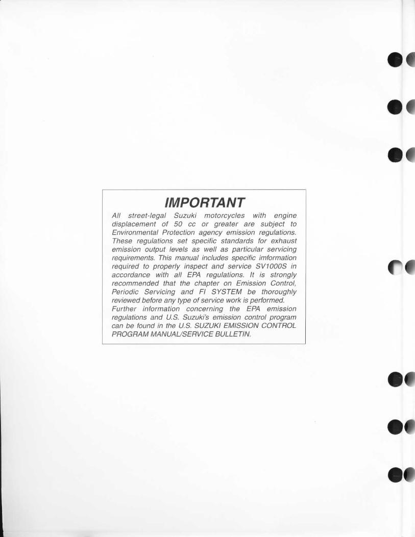
IMPORTANTAll street-legal Suzuki motorcycles with enginedisplacement of 50 cc or greater are subject toEnvironmental Protection agency emission regulations .These regulations set specific standards for exhaustemission output levels as well as particular servicingrequirements. This manual includes specific imformationrequired to properly inspect and service SV1000S inaccordance with all EPA regulations . It is stronglyrecommended that the chapter on Emission Control,Periodic Servicing and Fl SYSTEM be thoroughlyreviewed before any type of service work is performed .Further information concerning the EPA emissionregulations and U.S. Suzuki's emission control programcan be found in the U.S. SUZUKI EMISSION CONTROLPROGRAM MANUAUSERVICE BULLETIN.
1
0
01
f
40Ofof
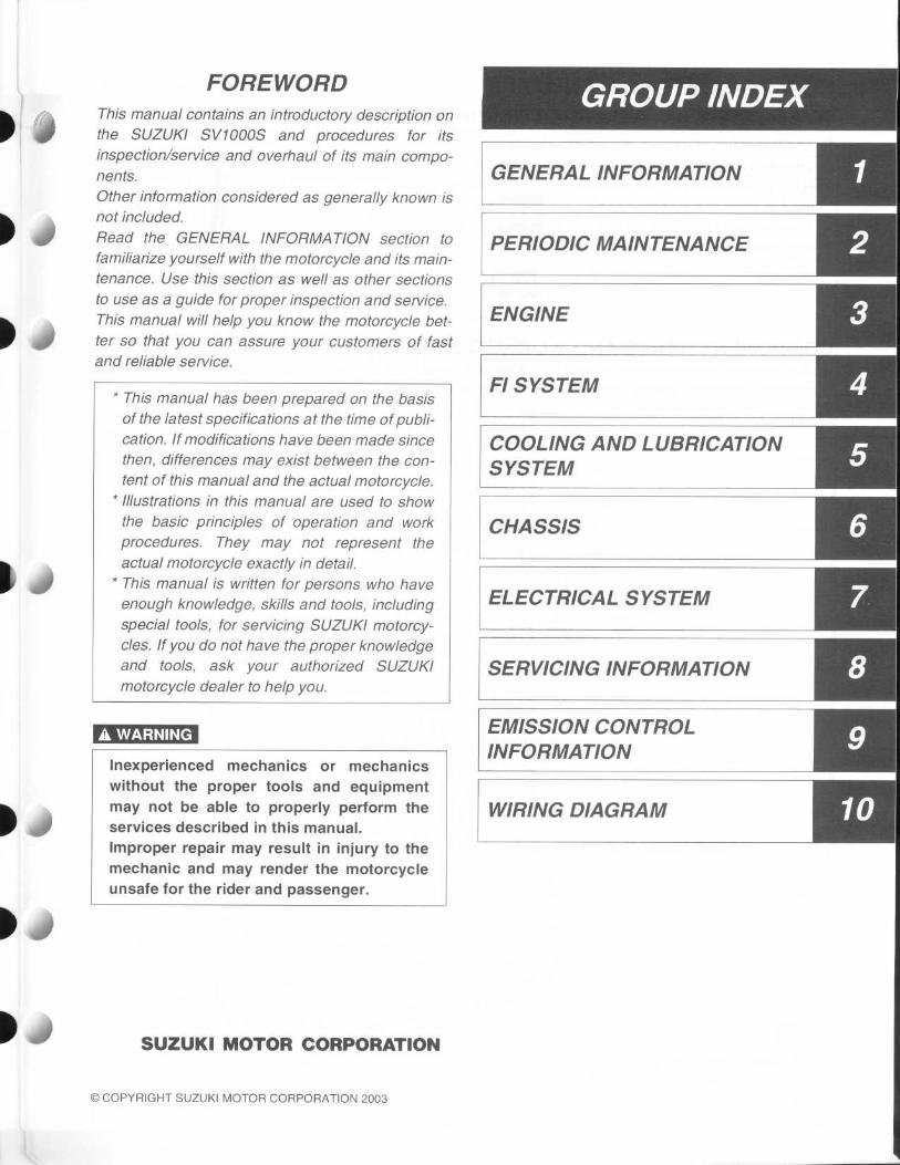
FOREWORDThis manual contains an introductory description onthe SUZUKI SV1000S and procedures for itsinspection/service and overhaul of its main compo-nents .Other information considered as generally known isnot included.Read the GENERAL INFORMATION section tofamiliarize yourself with the motorcycle and its main-tenance. Use this section as well as other sectionsto use as a guide for proper inspection and service .This manual will help you know the motorcycle bet-ter so that you can assure your customers of fastand reliable service .
* This manual has been prepared on the basisof the latest specifications at the time of publi-cation. If modifications have been made sincethen, differences may exist between the con-tent of this manual and the actual motorcycle .
* Illustrations in this manual are used to showthe basic principles of operation and workprocedures. They may not represent theactual motorcycle exactly in detail.
* This manual is written for persons who haveenough knowledge, skills and tools, includingspecial tools, for servicing SUZUKI motorcy-cles. If you do not have the proper knowledgeand tools, ask your authorized SUZUKImotorcycle dealer to help you .
may not be able to properly perform theservices described in this manual .Improper repair may result in injury to the
mechanic and may render the motorcycle
unsafe for the rider and passenger .
SUZUKI MOTOR CORPORATION
© COPYRIGHT SUZUKI MOTOR CORPORATION 2003
GROUP /NDE
GENERAL INFORMATION
PERIODIC MAINTENANCE
ENGINE
FI SYSTEM 4
COOLING AND LUBRICATIONSYSTEM
CHASSIS
ELECTRICAL SYSTEM ESERVICING INFORMATION
EMISSION CONTROLINFORMATION
WIRING DIAGRAM
A WARNING
Inexperienced mechanics or mechanicswithout the proper tools and equipment

HOW TO USE THIS MANUALTO LOCATE WHAT YOU ARE LOOKING FOR :1 . The text of this manual is divided into sections .2. The section titles are listed in the GROUP INDEX .3. Holding the manual as shown at the right will allow you to find
the first page of the section easily .4. The contents are listed on the first page of each section to
help you find the item and page you need .
COMPONENT PARTS AND WORK TO BE DONEUnder the name of each system or unit, is its exploded view . Work instructions and other service informationsuch as the tightening torque, lubricating points and locking agent points, are provided .
Example : Front wheel
0ITEM
CA)
N.m
100
23
kgf-m
10.0
2 .3
lb-ft
72 .5
165
1~ Brake disc•
Dust seal(3 Bearing•
Center spacer•
Coller•
Front wheel•
Tire valve
•
Front axle•
Brake disc bolt
T
44P
4 •
•
•
of

SYMBOLListed in the table below are the symbols indicating instructions and other information necessary for servic-ing . The meaning of each symbol is also included in the table .
SYMBOL DEFINITION SYMBOL DEFINITION
Torque control required .Data beside it indicates specifiedtorque .
LLC Use engine coolant .
0r
Apply oil. Use engine oil unless other-wise specified . FORK
Use fork oil .99000-99044-LO1
0
Apply molybdenum oil solution .(Mixture of engine oil and SUZUKIMOLY PASTE in a ratio of 1 : 1)
BF Apply or use brake fluid .
Apply SUZUKI SUPER GREASE "A" .99000-25030 Lo a
Measure in voltage range .
Apply SUZUKI MOLY PASTE .99000-25140 ~© a Measure in resistance range .
©Apply SUZUKI SILICONE GREASE .99000-25100 Lo o
Measure in current range .
Apply SUZUKI BOND "1207B" .99104-31 140 L o 0
Measure in diode test range .1207B
1303V
Apply THREAD LOCK SUPER "1303" .99000-32030
jL
1))o a
Measure in continuity test range .
1342Apply THREAD LOCK "1342" .99000-32050
Use special tool .TOOL
1360 Apply THREAD LOCK SUPER "1360" .99000-32130
Indication of service data .DATA
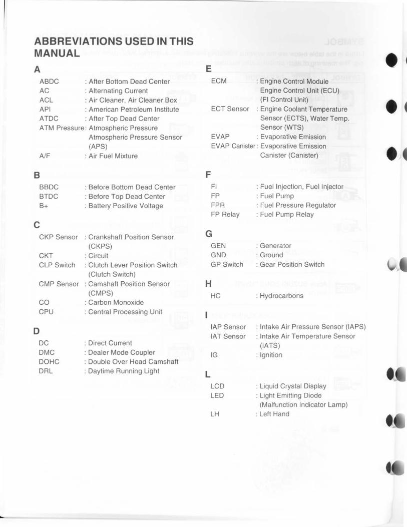
ABBREVIATIONS USED IN THISMANUALAABDC
: After Bottom Dead CenterAC
: Alternating CurrentACL
: Air Cleaner, Air Cleaner BoxAPI
: American Petroleum InstituteATDC
: After Top Dead CenterATM Pressure : Atmospheric Pressure
Atmospheric Pressure Sensor(APS)
A/F
: Air Fuel Mixture
BBBDC
: Before Bottom Dead CenterBTDC
: Before Top Dead CenterB+
: Battery Positive Voltage
CCKP Sensor : Crankshaft Position Sensor
(CKPS)CKT
: CircuitCLP Switch : Clutch Lever Position Switch
(Clutch Switch)CMP Sensor : Camshaft Position Sensor
(CMPS)CO
: Carbon MonoxideCPU
: Central Processing Unit
DDC
: Direct CurrentDMC
: Dealer Mode CouplerDOHC
: Double Over Head CamshaftDRL
: Daytime Running Light
EECM
: Engine Control ModuleEngine Control Unit (ECU)(FI Control Unit)
ECT Sensor : Engine Coolant TemperatureSensor (ECTS), Water Temp .Sensor (WTS)
EVAP
: Evaporative EmissionEVAP Canister : Evaporative Emission
Canister (Canister)
FFI
: Fuel Injection, Fuel InjectorFP
: Fuel PumpFPR
: Fuel Pressure RegulatorFP Relay
: Fuel Pump Relay
GGEN
: GeneratorGND
: GroundGP Switch
: Gear Position Switch
HHC
: Hydrocarbons
IAP Sensor
: Intake Air Pressure Sensor (ZAPS)IAT Sensor : Intake Air Temperature Sensor
(IATS)IG
: Ignition
LLCD
: Liquid Crystal DisplayLED
: Light Emitting Diode(Malfunction Indicator Lamp)
LH
: Left Hand
0 I
I
1
of,
4 6

• O
0
i
s1
i
•
I
MMAL-Code
MaxMIL
Min
NNOx
0OHCOPS
PPCV
RRHROM
SSAESTC System
STP Sensor
ST ValveSTV Actuator
TTO SensorTP Sensor
VVD
Malfunction Code(Diagnostic Code)MaximumMalfunction Indicator Lamp(LED)Minimum
Nitrogen Oxides
Over Head CamshaftOil Pressure Switch
Positive CrankcaseVentilation (Crankcase Breather)
Right HandRead Only Memory
Society of Automotive EngineersSecondary Throttle ControlSystem (STCS)Secondary Throttle PositionSensor (STPS)Secondary Throttle Valve (STV)Secondary Throttle Valve Actuator(STVA)
Tip Over Sensor (TOS)Throttle Position Sensor (TPS)
Vacuum Damper

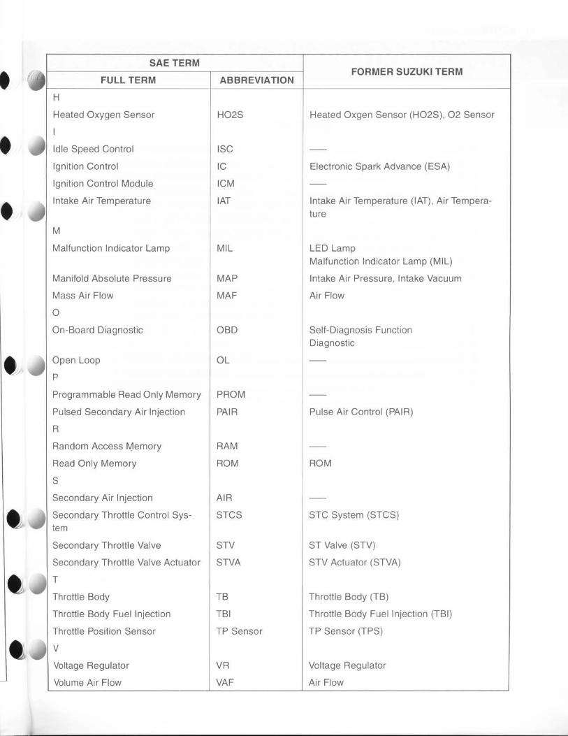
SAE-TO-FORMER SUZUKI TERMThis table lists SAE (Society of Automotive Engineers) J1930 terms and abbreviations which may be used inthis manual in compliance with SAE recommendations, as well as their former SUZUKI names .
it
1•
06
46
1
1
4
SAE TERMFULL TERMABBREVIATIONFORMER SUZUKI TERMA
Air Cleaner ACL Air Cleaner, Air Cleaner Box
B
Barometric Pressure BARO Barometric Pressure, Atmospheric
Battery Positive Voltage B+
Pressure (APS, AP Sensor)
Battery Voltage, +B
C
Camshaft Position Sensor CMP Sensor Camshaft Position Sensor (CMPS)
Crankshaft Position Sensor CKP Sensor Crankshaft Position Sensor (CKPS),
D
Data Link Connector DLC
Crank Angle
Dealer Mode Coupler
Diagnostic Test Mode
Diagnostic Trouble Code
DTM
DTC Diagnostic Code, Malfunction Code
E
Electronic Ignition
Engine Control Module
El
ECM Engine Control Module (ECM)
Engine Coolant Level ECL
Fl Control Unit, Engine Control Unit (ECU)
Coolant Level
Engine Coolant Temperature ECT Coolant Temperature, Engine Coolant Tem-
Engine Speed RPM
peratureWater Temperature
Engine Speed (RPM)
Evaporative Emission EVAP Evaporative Emission
Evaporative Emission Canister EVAP Canister (Canister)
Purge Valve Purge Valve Purge Valve (SP Valve)
F
Fan Control
Fuel Level Sensor
FC
Fuel Level Sensor, Fuel Level Gauge
Fuel Pump FP Fuel Pump (FP)
G
Generator GEN Generator
Ground GND Ground (GND, GRD)
•
I
SAE TERM
FULL TERM ABBREVIATIONFORMER SUZUKI TERM
H
Heated Oxygen Sensor HO2S Heated Oxgen Sensor (HO2S), 02 Sensor
I
Idle Speed Control
Ignition Control
ISC
IC Electronic Spark Advance (ESA)
Ignition Control Module
Intake Air Temperature
ICM
IAT Intake Air Temperature (IAT), Air Tempera-
M
Malfunction Indicator Lamp MIL
ture
LED Lamp
Manifold Absolute Pressure MAP
Malfunction Indicator Lamp (MIL)
Intake Air Pressure, Intake Vacuum
Mass Air Flow MAF Air Flow
0
On-Board Diagnostic OBD Self-Diagnosis Function
Open Loop
P
Programmable Read Only Memory
Pulsed Secondary Air Injection
OL
PROM
PAIR
Diagnostic
Pulse Air Control (PAIR)
R
Random Access Memory
Read Only Memory
RAM
ROM ROM
S
Secondary Air Injection
Secondary Throttle Control Sys-
AIR
STCS STC System (STCS)tem
Secondary Throttle Valve STV ST Valve (STV)
Secondary Throttle Valve Actuator STVA STV Actuator (STVA)
T
Throttle Body TB Throttle Body (TB)
Throttle Body Fuel Injection TBI Throttle Body Fuel Injection (TBI)
Throttle Position Sensor TP Sensor TP Sensor (TPS)
V
Voltage Regulator VR Voltage Regulator
Volume Air Flow VAF Air Flow

. GENERAL INFORMATION
6- r
6- )
4)
CONTENTS
WARNING/CAUTION/NOTE 1- 2GENERAL PRECAUTIONS 1- 2SUZUKI SV1000SK3 ('03-MODEL) 1- 4SERIAL NUMBER LOCATION 1- 4FUEL, OIL AND ENGINE COOLANT RECOMMENDATION1- 4
FUEL (FOR USA AND CANADA) 1- 4FUEL (FOR OTHER COUNTRIES) 1- 4ENGINE OIL 1- 5BRAKE FLUID 1- 5FRONT FORK OIL 1- 5ENGINE COOLANT 1- 5WATER FOR MIXING 1- 5ANTI-FREEZE/ENGINE COOLANT 1- 5LIQUID AMOUNT OF WATER/ENGINE COOLANT1- 5
BREAK-IN PROCEDURES 1- 6CYLINDER IDENTIFICATION 1- 6INFORMATION LABELS 1- 7SPECIFICATIONS 1- 8COUNTRY AND AREA CODES 1-10
GENERAL INFORMATION 1 -1
1
1-2 GENERAL INFORMATION
WARNING/CAUTION/NOTEPlease read this manual and follow its instructions carefully . To emphasize special information, the symboland the words WARNING, CAUTION and NOTE have special meanings . Pay special attention to the mes-sages highlighted by these signal words .
A WARNINGIndicates a potential hazard that could result in death or injury .
CAUTION
Indicates a potential hazard that could result in motorcycle damage .
NOTE:
Indicates special information to make maintenance easier or instructions clearer.
Please note, however, that the warnings and cautions contained in this manual cannot possibly cover allpotential hazards relating to the servicing, or lack of servicing, of the motorcycle . In addition to the WARN-INGS and CAUTIONS stated, you must use good judgement and basic mechanical safety principles . If youare unsure about how to perform a particular service operation, ask a more experienced mechanic foradvice .
GENERAL PRECAUTIONSA WARNING
•
Proper service and repair procedures are important for the safety of the service mechanic andthe safety and reliability of the motorcycle .
•
When 2 or more persons work together, pay attention to the safety of each other .•
When it is necessary to run the engine indoors, make sure that exhaust gas is forced out-doors .
•
When working with toxic or flammable materials, make sure that the area you work in is well-ventilated and that you follow all of the material manufacturer's instructions .
•
Never use gasoline as a cleaning solvent .•
To avoid getting burned, do not touch the engine, engine oil, radiator and exhaust systemuntil they have cooled .
•
After servicing the fuel, oil, water, exhaust or brake systems, check all lines and fittingsrelated to the system for leaks .

1 40
4
1
0 I
0 0
CAUTION
GENERAL INFORMATION 1-3
•
If parts replacement is necessary, replace the parts with Suzuki Genuine Parts or their equiva-lent .
•
When removing parts that are to be reused, keep them arranged in an orderly manner so thatthey may be reinstalled in the proper order and orientation .
•
Be sure to use special tools when instructed .•
Make sure that all parts used in reassembly are clean. Lubricate them when specified .•
Use the specified lubricant, bond or sealant .•
When removing the battery, disconnect the negative cable first and then the positive cable .•
When reconnecting the battery, connect the positive cable first and then the negative cable,and replace the terminal cover on the positive terminal .
•
When performing service to electrical parts, if the service procedures not require use of bat-tery power, disconnect the negative cable the battery .
• When tightening the cylinder head and case bolts and nuts, tighten the larger sizes first .Always tighten the bolts and nuts diagonally from the inside toward outside and to the speci-fied tightening torque .
• Whenever you remove oil seals, gaskets, packing, 0-rings, locking washers, self-lockingnuts, cotter pins, circlips and certain other parts as specified, be sure to replace them withnew ones . Also, before installing these new parts, be sure to remove any left over materialfrom the mating surfaces .
• Never reuse a circlip . When installing a new circlip, take care not to expand the end gap largerthan required to slip the circlip over the shaft . After installing a circlip, always ensure that it iscompletely seated in its groove and securely fitted .
•
Use a torque wrench to tighten fasteners to the specified torque. Wipe off grease and oil if athread is smeared with them .
•
After reassembling, check parts for tightness and proper operation .
•
To protect the environment, do not unlawfully dispose of used motor oil, engine coolant andother fluids : batteries and tires .
•
To protect Earth's natural resources, properly dispose of used motorcycle and parts .
1-4 GENERAL INFORMATION
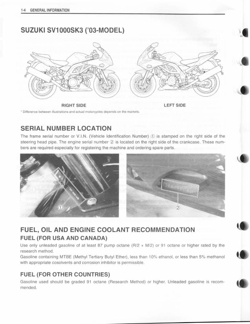
SUZUKI SV1000SK3 ('03-MODEL)
RIGHT SIDEDifference between illustrations and actual motorcycles depends on the markets .
LEFT SIDE
SERIAL NUMBER LOCATIONThe frame serial number or V .I.N . (Vehicle Identification Number) 1O is stamped on the right side of thesteering head pipe . The engine serial number 2 is located on the right side of the crankcase . These num-bers are required especially for registering the machine and ordering spare parts .
FUEL, OIL AND ENGINE COOLANT RECOMMENDATIONFUEL (FOR USA AND CANADA)Use only unleaded gasoline of at least 87 pump octane (R/2 + M/2) or 91 octane or higher rated by theresearch method .Gasoline containing MTBE (Methyl Tertiary Butyl Ether), less than 10% ethanol, or less than 5% methanolwith appropriate cosolvents and corrosion inhibitor is permissible .
FUEL (FOR OTHER COUNTRIES)Gasoline used should be graded 91 octane (Research Method) or higher . Unleaded gasoline is recom-mended .
4
41
01
ko
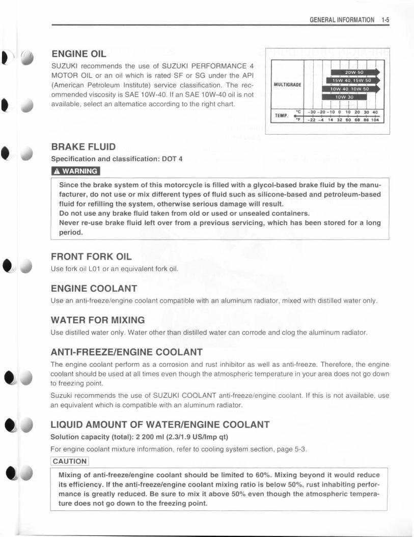
ENGINE OILSUZUKI recommends the use of SUZUKI PERFORMANCE 4MOTOR OIL or an oil which is rated SF or SG under the API(American Petroleum Institute) service classification . The rec-ommended viscosity is SAE 1 OW-40 . If an SAE 1 OW-40 oil is notavailable, select an altematice according to the right chart .
BRAKE FLUIDSpecification and classification : DOT 4
A WARNING
Since the brake system of this motorcycle is filled with a glycol-based brake fluid by the manu-facturer, do not use or mix different types of fluid such as silicone-based and petroleum-basedfluid for refilling the system, otherwise serious damage will result .Do not use any brake fluid taken from old or used or unsealed containers .Never re-use brake fluid left over from a previous servicing, which has been stored for a longperiod .
FRONT FORK OILUse fork oil L01 or an equivalent fork oil .
GENERAL INFORMATION 1 -5
ENGINE COOLANTUse an anti-freeze/engine coolant compatible with an aluminum radiator, mixed with distilled water only .
WATER FOR MIXINGUse distilled water only . Water other than distilled water can corrode and clog the aluminum radiator .
ANTI-FREEZE/ENGINE COOLANTThe engine coolant perform as a corrosion and rust inhibitor as well as anti-freeze . Therefore, the enginecoolant should be used at all times even though the atmospheric temperature in your area does not go downto freezing point .
Suzuki recommends the use of SUZUKI COOLANT anti-freeze/engine coolant . If this is not available, usean equivalent which is compatible with an aluminum radiator .
LIQUID AMOUNT OF WATER/ENGINE COOLANTSolution capacity (total) : 2 200 ml (2 .3/1 .9 US/Imp qt)
For engine coolant mixture information, refer to cooling system section, page 5-3 .
CAUTION
Mixing of anti-freeze/engine coolant should be limited to 60% . Mixing beyond it would reduceits efficiency . If the anti-freeze/engine coolant mixing ratio is below 50%, rust inhabiting perfor-mance is greatly reduced . Be sure to mix it above 50% even though the atmospheric tempera-ture does not go down to the freezing point .
MUITIGRADE
20W-5015W-40, 15W 50
1OW 40 . 10W 50
10W 30
°C -30 -20 -10 0 10 20 30 40TEMP . 0 1
1 +
1
t
+
I 1°F -22 -4 14 32 50 68 86 104
1-6 GENERAL INFORMATION
BREAK-IN PROCEDURESDuring manufacture only the best possible materials are used and all machined parts are finished to a veryhigh standard but it is still necessary to allow the moving parts to "BREAK-IN" before subjecting the engineto maximum stresses . The future performance and reliability of the engine depends on the care and restraintexercised during its early life . The general rules are as follows :
•
Keep to these break-in engine speed limits :
Initial 800 km ( 500 miles): Below 6 000 r/minUp to 1 600 km (1 000 miles) : Below 9 000 r/minOver 1 600 km (1 000 miles) : Below 12 500 r/min
•
Upon reaching an odometer reading of 1 600 km (1 000 miles) you can subject the motorcycle to full throt-tle operation . However, do not exceed 12 500 r/min at any time .
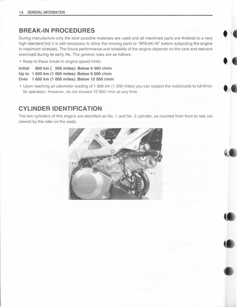
CYLINDER IDENTIFICATIONThe two cylinders of this engine are identified as No. 1 and No . 2 cylinder, as counted from front to rear (asviewed by the rider on the seat) .
6 41
4 16
$6
l1
(a
V
dP
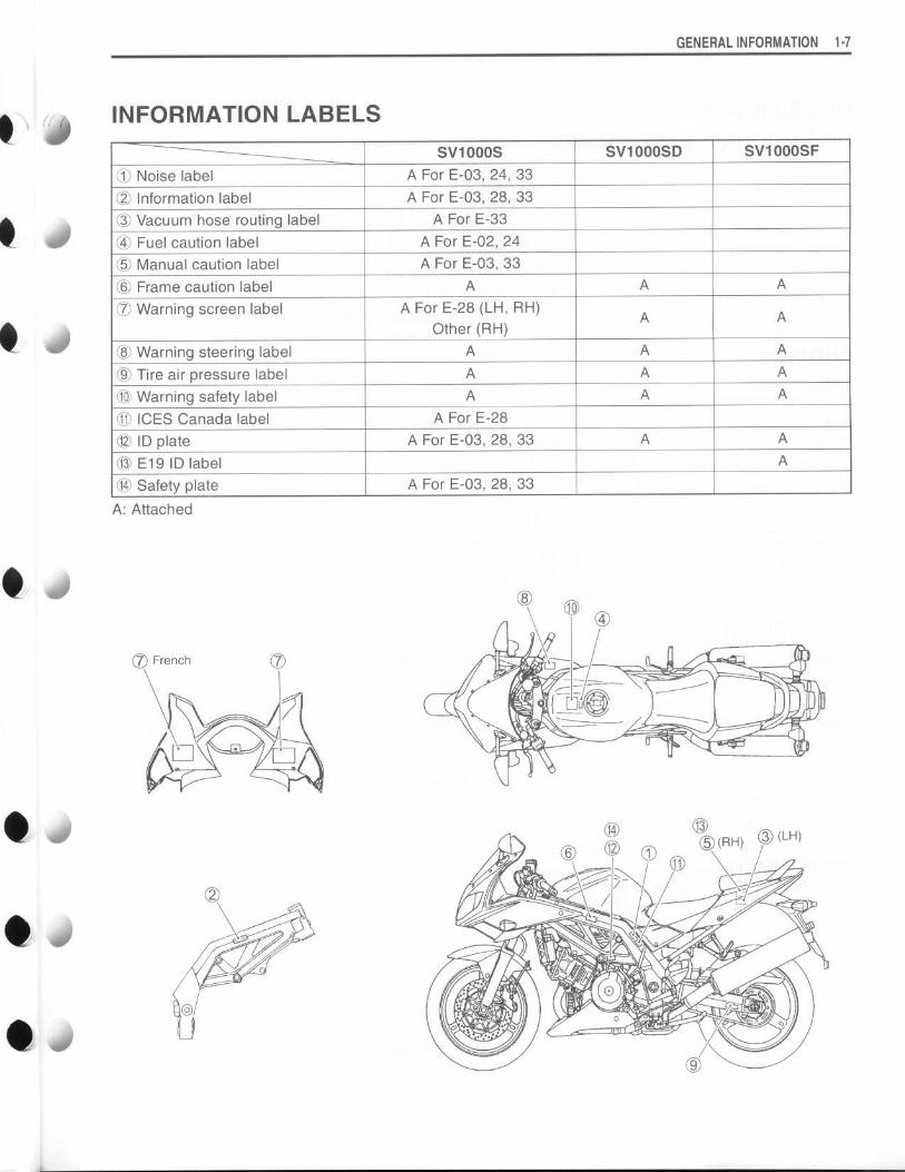
INFORMATION LABELS
A: Attached
(7 French
GENERAL INFORMATION 1-7
SV1000S SV1000SD SV1000SF
1O Noise label A For E-03, 24, 33
O2 Information label A For E-03, 28, 33
03 Vacuum hose routing label A For E-33
(4) Fuel caution label A For E-02, 24
($ Manual caution label A For E-03, 33
© Frame caution label A A A
O7 Warning screen label A For E-28 (LH, RH)
Other (RH) A A
® Warning steering label A A A
O Tire air pressure label A A A
C0) Warning safety label A A A
11 ICES Canada label A For E-28
ID plate A For E-03, 28, 33 A A
13 E19 ID label A
14 Safety plate A For E-03, 28, 33
1-8 GENERAL INFORMATION
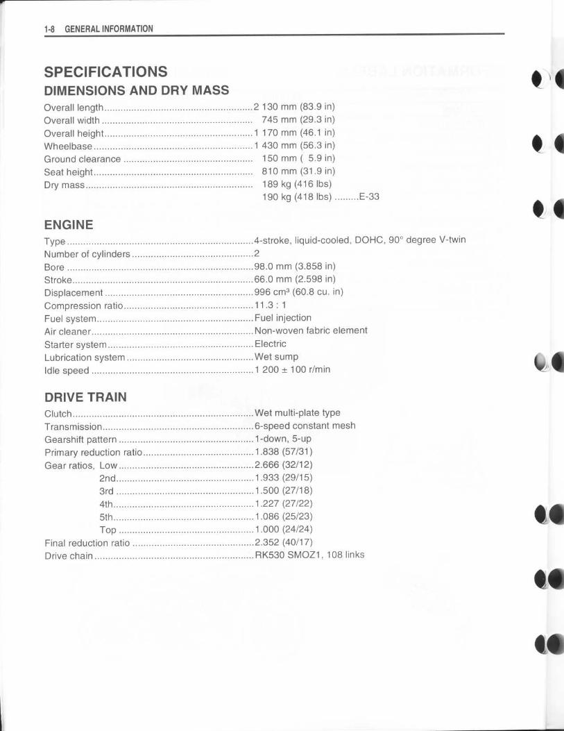
SPECIFICATIONSDIMENSIONS AND DRY MASSOverall length 2 130 mm (83 .9 in)Overall width 745 mm (29 .3 in)Overall height 1 170 mm (46 .1 in)Wheelbase 1 430 mm (56 .3 in)Ground clearance 150 mm ( 5 .9 in)Seat height 810 mm (31 .9 in)Dry mass 189 kg (416 Ibs)
190 kg (418 Ibs)E-33
ENGINEType 4-stroke, liquid-cooled, DOHC, 90° degree V-twinNumber of cylinders 2Bore 98.0 mm (3.858 in)Stroke 66.0 mm (2 .598 in)Displacement 996 cm3 (60.8 cu. in)Compression ratio 11 .3 : 1Fuel system Fuel injectionAir cleaner Non-woven fabric elementStarter system ElectricLubrication system Wet sumpIdle speed 1 200 ± 100 r/min
DRIVE TRAINClutch Wet multi-plate typeTransmission 6-speed constant meshGearshift pattern 1-down, 5-upPrimary reduction ratio1 .838 (57/31)Gear ratios, Low 2.666 (32/12)
2nd 1 .933 (29/15)3rd 1 .500 (27/18)4th 1 .227 (27/22)5th 1 .086 (25/23)Top 1 .000 (24/24)
Final reduction ratio 2.352 (40/17)Drive chain RK530 SMOZ1, 108 links
t1
$4
l1
$•
t•
40
0 .l
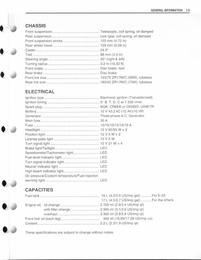
CHASSISFront suspension Telescopic, coil spring, oil dampedRear suspension Link type, coil spring, oil dampedFront suspension stroke120 mm (4 .72 in)Rear wheel travel 129 mm (5 .08 in)Caster 24.5°Trail 98 mm (3 .9 in)Steering angle 30° (right & left)Turning radius 3.2 m (10.50 ft)Front brake Disc brake, twinRear brake Disc brakeFront tire size 120/70 ZR17M/C (58W), tubelessRear tire size 180/55 ZR1 7M/C (73W), tubeless
ELECTRICALIgnition type Electronic ignition (Transistorized)Ignition timing 5° B . T. D. C at 1 200 r/minSpark plug NGK: CR8EK or DENSO : U24ETRBattery 12 V 43.2 kC (12 Ah)/10 HRGenerator Three-phase A.C . GeneratorMain fuse 30 AFuse 15/15/10/15/15/10 AHeadlight 12 V 60/55 W x 2Position light 12 V 5 W x 2License plate light 12 V 5 WTurn signal light 12V21 W x 4Brake light/Taillight LEDSpeedometer/Tachometer lightLEDFuel level indicator lightLEDTurn signal indicator lightLEDNeutral indicator lightLEDHigh beam indicator lightLEDOil pressure/Coolant temperature/Fuel injectionwarning light LED
CAPACITIESFuel tank 16 L (4.2/3 .5 US/Imp gal)For E-33
17 L (4.5/3 .7 US/Imp gal)For the othersEngine oil, oil change2 700 ml (2 .9/2 .4 US/Imp qt)
with filter change2 900 ml (3 .1/2 .6 US/Imp qt)overhaul 3 300 ml (3 .5/2 .9 US/Imp qt)
Front fork oil (each leg)494 ml (16.69/17.39 US/Imp oz)Coolant 2.2 L (2.3/1 .9 US/Imp qt)
These specifications are subject to change without notice .
GENERAL INFORMATION 1-9

1-10 GENERAL INFORMATION
COUNTRY AND AREA CODESThe following codes stand for the applicable country(-ies) and area(-s) .
CODE COUNTRY or AREA
E-02 U. K .
E-03 U. S . A . (Except for California)
E-19 EU
E-24 Australia
E-28 Canada
E-33 California (U . S . A .)