eztune manual 5 - gold-line-europe · check for room modes with 1/12th octave rta 5. ... supply...
TRANSCRIPT
1
EZTune Manual A Guide to installing and using your
TEF25 Analyzer with EZTune Software
Gold Line, PO Box 500, W. Redding, CT 06896 Tel (203) 938 2588, Fax (203) 938 8740
www.gold-line.com
2
Please Read this Manual Before Installing the TEF Software
The enclosed manual will guide you through the easy install process and will provide you with information as to how to use your EZTune System to calibrate a Home Theater. The manual is also part of the EZTune software and can be accessed at any time while you are running the program by clicking on the “?” mark symbol on the toolbar or by clicking on Help, Contents and EZTune.
Index Intro- The Test Sequence Included Hardware/Software Computer Requirements Chapters- 1. Installing the Software 2. Connect the Hardware 3. Launching the Software 4. Connecting the Microphone 5. Connect TEF25 to your Home Theater 6. The TK5.1 DVD (Test Tones) 7. Overview of EZTune Hot Keys 8. NC Tests (Noise Criteria) 9. SPL Tests (Reference Levels) 10. RTA Tests (1/3, 1/12, 1/24) & Modal Tests 11. Reflection Tests 12. Frequency Tests 13. Aiming Loudspeakers 14. Determining EQ Settings 15. Final Steps Conclusion- Listening Tests Frequency Asked Questions - Specifications-

3
Manual for EZTune™ Home Theater Analysis
with TEF25 Audio Analyzer and EZTune Software By Gregory Miller
Manufactured by TEF Division of Gold Line PO Box 500, W. Redding, CT 06896 (203) 938 2588, Fax 8740
www.gold- line.com September 2005
Thank you for purchasing a TEF EZTune System. This manual covers the basic procedures for utilizing the equipment to calibrate a home theater. We have sought to make the system very intuitive, but please take the time to read this manual before us ing your TEF. The tuning process is based on a 10 step process.
1. Set Reference Level with SPL Function 2. Check Ambient Noise with NC Function 3. Check crossover splice and system operation with 1/3rd Octave RTA 4. Check for Room Modes with 1/12th Octave RTA 5. Zoom in on the Modes down to 11Hz with our 1/24th Octave RTA 6. Model the Room Modes with MODAL analysis 7. Measure Discrete Reflections with Reflection Mode 8. Measure Early Decay in the Room with the Decay Mode 9. Auto Calculate Equalizable from Un-equalizable response Frequency Mode 10. Auto Calculate optimal Equalization EQ Mode
Components in the EZTune System: Included with your system should be:
a. TEF25 USB Preamp, b. TEF04 microphone, c. 20’ mic cable, d. TEF EZTune Software CD, e. USB Cable, f. XLR to RCA adapter, g. Carry case and h. Microphone stand. i. TK5.1 DVD j. RCA to Y Connector Adapter
Computer- To run the program you will need a computer running windows with a USB port and a CD Rom. We recommend Win 2000 or XP for use with EZTune. This manual describes the procedure to make the test and also has TIPS, which are notes about how we solve common problems and NOTES, which are related information.
4
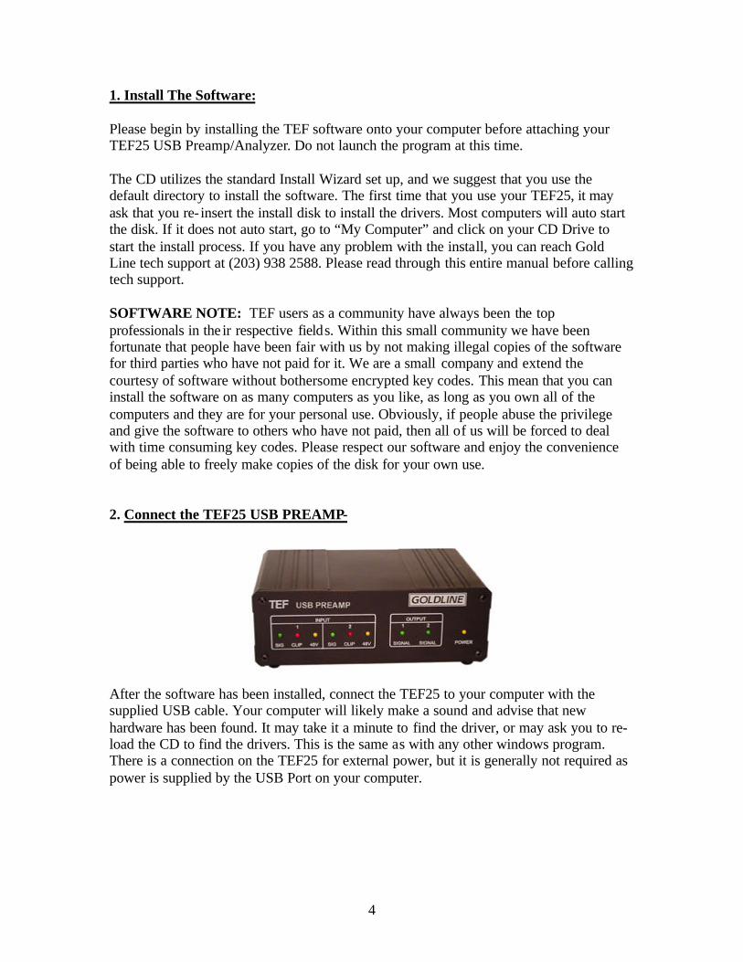
1. Install The Software: Please begin by installing the TEF software onto your computer before attaching your TEF25 USB Preamp/Analyzer. Do not launch the program at this time. The CD utilizes the standard Install Wizard set up, and we suggest that you use the default directory to install the software. The first time that you use your TEF25, it may ask that you re- insert the install disk to install the drivers. Most computers will auto start the disk. If it does not auto start, go to “My Computer” and click on your CD Drive to start the install process. If you have any problem with the install, you can reach Gold Line tech support at (203) 938 2588. Please read through this entire manual before calling tech support. SOFTWARE NOTE: TEF users as a community have always been the top professionals in the ir respective fields. Within this small community we have been fortunate that people have been fair with us by not making illegal copies of the software for third parties who have not paid for it. We are a small company and extend the courtesy of software without bothersome encrypted key codes. This mean that you can install the software on as many computers as you like, as long as you own all of the computers and they are for your personal use. Obviously, if people abuse the privilege and give the software to others who have not paid, then all of us will be forced to deal with time consuming key codes. Please respect our software and enjoy the convenience of being able to freely make copies of the disk for your own use. 2. Connect the TEF25 USB PREAMP-
After the software has been installed, connect the TEF25 to your computer with the supplied USB cable. Your computer will likely make a sound and advise that new hardware has been found. It may take it a minute to find the driver, or may ask you to re-load the CD to find the drivers. This is the same as with any other windows program. There is a connection on the TEF25 for external power, but it is generally not required as power is supplied by the USB Port on your computer.
5
3. Launch the Software- Click on the TEF Software icon on your desktop. The EZTune interface will open, then at the bottom of the screen you will see the TEF begin to communicate with your computer. First it will say Initializing TEF Preamp, then Loading Drivers, and then a green face will come up on the communications icon, and in a few more seconds it will turn to a yellow happy face to indicate that communications has been fully established. The process takes around 30 seconds. Real World Tips- We normally connect our computer to the projector so that we can see the data up on the screen or the Video Monitor in the Home Theater. Not essential, but useful if practical. Otherwise, you will see the data on your computer screen. 4. Connect the Microphone -
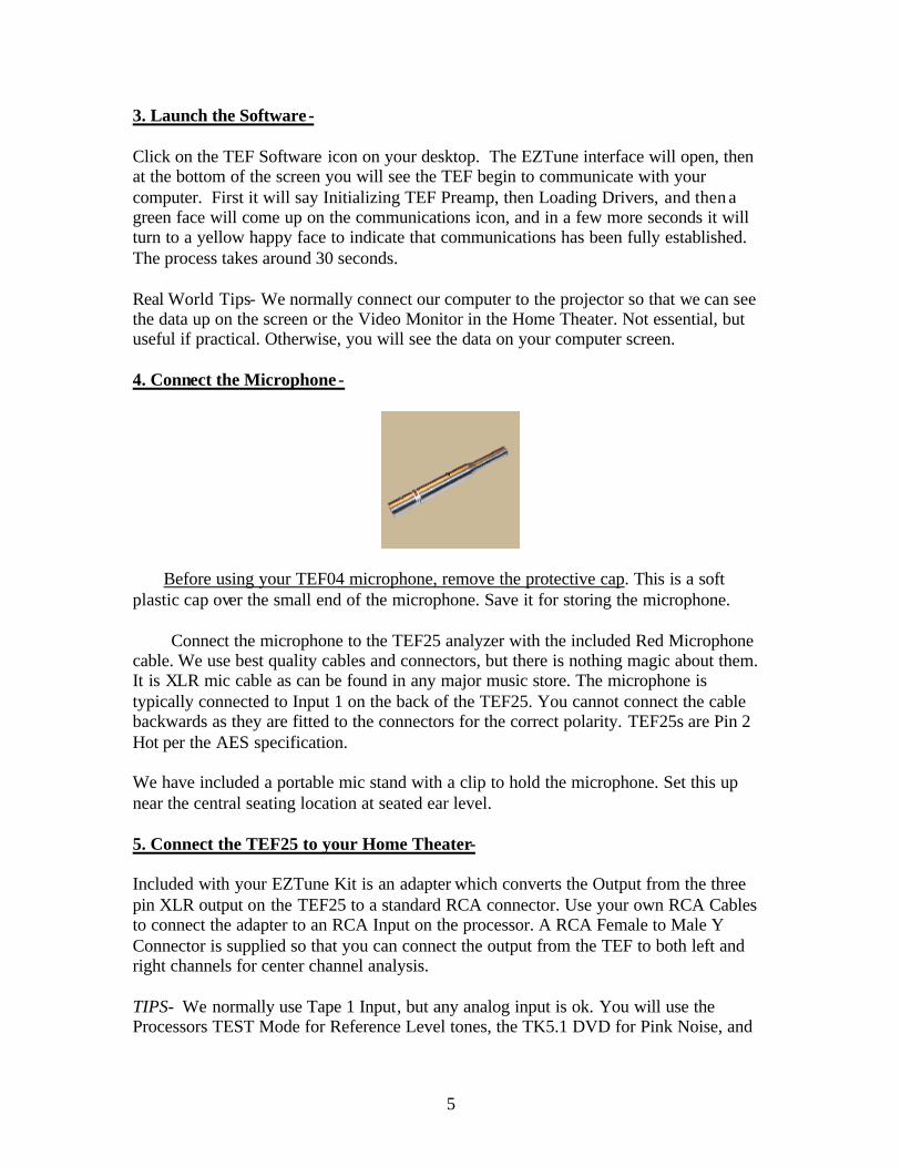
Before using your TEF04 microphone, remove the protective cap. This is a soft plastic cap over the small end of the microphone. Save it for storing the microphone. Connect the microphone to the TEF25 analyzer with the included Red Microphone cable. We use best quality cables and connectors, but there is nothing magic about them. It is XLR mic cable as can be found in any major music store. The microphone is typically connected to Input 1 on the back of the TEF25. You cannot connect the cable backwards as they are fitted to the connectors for the correct polarity. TEF25s are Pin 2 Hot per the AES specification. We have included a portable mic stand with a clip to hold the microphone. Set this up near the central seating location at seated ear level. 5. Connect the TEF25 to your Home Theater- Included with your EZTune Kit is an adapter which converts the Output from the three pin XLR output on the TEF25 to a standard RCA connector. Use your own RCA Cables to connect the adapter to an RCA Input on the processor. A RCA Female to Male Y Connector is supplied so that you can connect the output from the TEF to both left and right channels for center channel analysis. TIPS- We normally use Tape 1 Input, but any analog input is ok. You will use the Processors TEST Mode for Reference Level tones, the TK5.1 DVD for Pink Noise, and

6
the TEF25 for the swept sine wave test tones. To feed the center channel, use the included RCA Y connector to feed signal to left and right channels. 6. The TK5.1 DVD- Pink Noise for certain tests are produced by the TK5.1 DVD included with your kit. Place it into your DVD in the home theater system. You may want to review the disk prior to starting measurements to familiarize yourself with it. The disk is divided into Acoustical tests, Electrical Tests, Listening Tests, product information on Gold Line and PMI (Grimani) and a Tutorial with general concepts related to home theater measurement with the DVD.
The basic test sequence on the disk includes. • Midrange Pink Noise • Wideband Pink Noise
• LF Pink Noise • ½ Point Check Signals
• Imaging Tests • 1/3 Octave Pink Noise • 1 Octave Pink Noise
• 1/3 Octave Burst Headroom Test • Noise Leakage Tests
• Sinewave Signals • Swept Sinewave Signals
• 5.1 Channel Music • ... and "A Whole Lotta Bass"
The DVD was produced for Gold Line by Anthony Grimani, President of Performance Media Industries, Ltd and formerly of LucasFilm. A who’s who from the industry including THX and Dolby supported the project, for which we are deeply grateful. The disk was nominated for the Prestigious Recording Industry Tech Award in the category of Outstanding Technical Achievement.
7
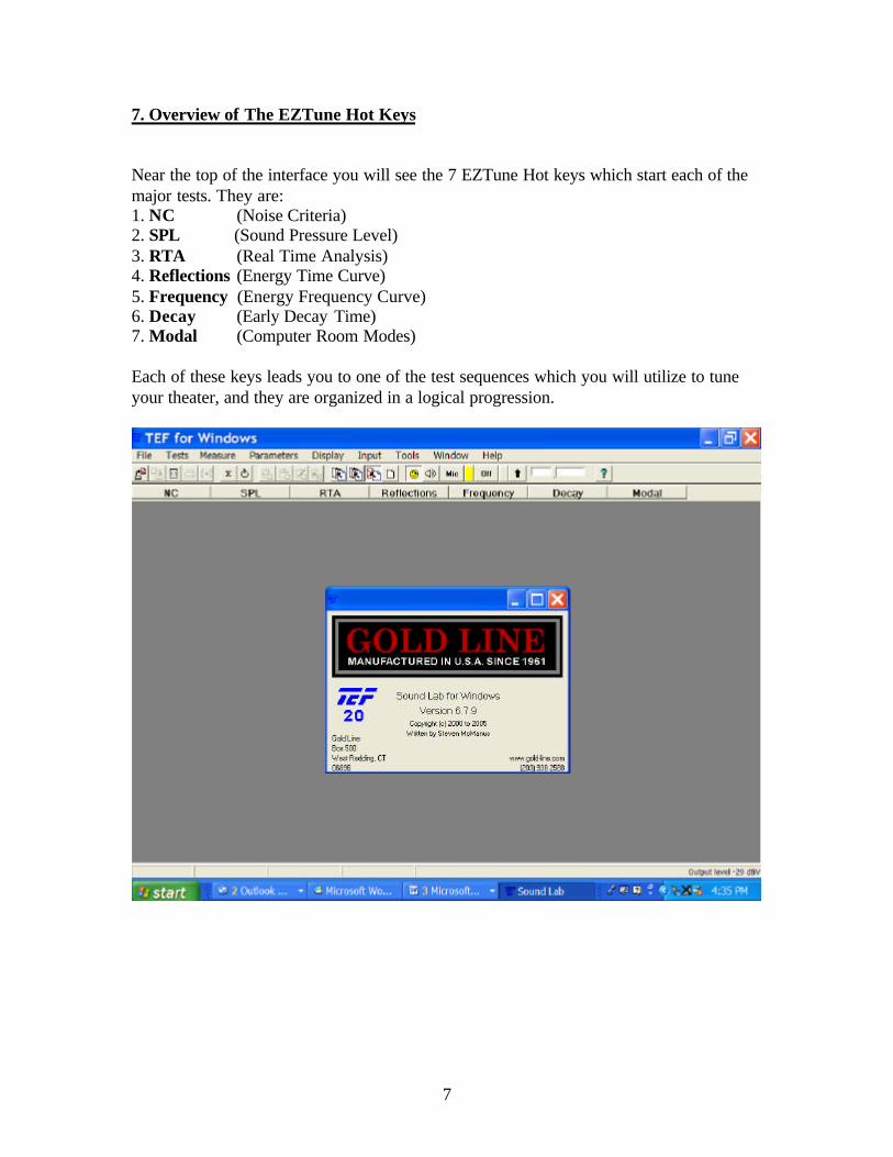
7. Overview of The EZTune Hot Keys Near the top of the interface you will see the 7 EZTune Hot keys which start each of the major tests. They are: 1. NC (Noise Criteria) 2. SPL (Sound Pressure Level) 3. RTA (Real Time Analysis) 4. Reflections (Energy Time Curve) 5. Frequency (Energy Frequency Curve) 6. Decay (Early Decay Time) 7. Modal (Computer Room Modes) Each of these keys leads you to one of the test sequences which you will utilize to tune your theater, and they are organized in a logical progression.

8
8. NC (Noise Criteria) NC is an abbreviation for Noise Criteria. NC is a method to evaluate the very low level ambient noises in a room. We care about ambient noise as it tends to mask the subtle details (Foley effects) in a film and as they distract the listener from the film experience. In extreme cases noise will also mask the speech in the film, making it difficult to understand the dialogue. Noise criteria’s are a type of sound level measurement. The human ear at low levels predominantly hears mid-frequency sound, so to measure the equivalent perceived equal loudness contours, the analyzer applies the NC scales and then rates the room. In general a home theater should be NC35 or lower, and NC30 is preferable. The lower the number the better. Tip: The lowest number you can typically measure with the basic TEF mic in your kit is NC25, which is adequate for 99.9% of all dedicated home theaters. If you are in the 1/10th of 1% who work below that number or are working in a laboratory setting, we can supply mics that can approach the limits of human perception.
Making the Test- To begin the NC Measurement, press the NC Hot Key. You will see a display with several octave bands of frequencies and will see the overlays for the NC curves. The NC Rating will be at the top of the screen. TIPS- Start your NC test with all of the audio equipment and the HVAC turned off. Press the Capture key to save the spectrum on the screen. There will now be two curves, the moving one is live, and the fixed one is the one you just saved. Now turn on the audio gear (no test signal just gear on), and again press capture. The NC box will now show the rating for the room with the audio gear on. Now turn on the HVAC and audio system. You can now see the effective NC when the system is running.

9
To move between curves press page up or page down. By comparing these curves you can see where the ambient noise is coming from: room, audio or HVAC. Another trick is to use the mic as a sniffer, move it close to the bottom of doors, HVAC ducts, fans and look for the source of the no ise. As you get close to the noise source sound levels will rise. NC Rating- To achieve an actual NC rating for the room, I place the microphone in the central seating position, on the mic stand, at ear level. If your computer has a fan that runs, get it far from the microphone, and wait approximately 45 seconds for the data to settle down. People should not be moving nor making any sound while this is occurring, as even small noises can affect the rating. 9. SPL Test- (Set Reference Levels) The SPL (Sound Pressure Level) test is actually run twice, once at the beginning of system calibration, and again at the end of the calibration process. When you click on the SPL Hot Key it will show you a large display with the SPL in the room. We use the standard THX method with C weighting and slow decay.
Making the SPL Test. When you click on the SPL Hot Key the program will prompt you that the normal reference level is 75dB SPL. Click OK to confirm. To make the test you will need to get the system’s surround processor into TEST mode. Your processor’s manual will advice you how to get to test mode. I prefer processors that allow the test of one channel at a time. Others processors will cycle through all loudspeakers. The purpose of the test is to get all loudspeakers adjusted to 75dB as measured at ear level from the
10
central listening position. The EZTune screen will be blue if you are under 74dB, Red if over 76dB and Green when close to 75dB. If you want to see the levels to the 1/10th of a dB, it is in small numbers above the main display. The 1/10th dB display will jump around a little due to the nature of pink noise, which is pseudo random. TIP- Theory behind the Test Mode for Reference Levels. Why We Set Reference Levels. All quality surround processors have a TEST Mode . The purpose of the test mode is two fold. First it calibrates the acoustical image with the video image. This means that when the jet flies to the left, the sound follows the image. Generally, the brain perceives sound as coming from the direction where it is the loudest. If it is exactly the same level from both sides, then we perceive the sound as coming from directly in front of us. This is somewhat simplified, but the concept explains why we need to set reference levels. If one loudspeaker is louder than it should be, the image will be shifted towards that loudspeaker. The Test Mode allows us to calibrate a reference level for all loudspeakers, so that they produce equal sound when sent equal energy. The second reason for the Test Mode is to match the level in the theater to the level intended by the director. Most home theater systems have finite amounts of gain. If we turn them up loud enough, eventually the system will begin to distort. So, movies are mixed to remain within the realm of performance available from typical audio systems. Additionally, the maximum level of the sound should not be so loud that serious injury is likely to occur. As a General Rule, the loudest effects in a movie should not exceed 105dB SPL C weighted. Conversations in the movie should be loud enough to be heard clearly, and subtle audio cues (Foley effects), should be at the levels that we would expect. Footsteps should normally be fairly quiet, but need to be audible. All of these fine balances are set in the film by the producer, but to reproduce them your Audio System must be calibrated to the same reference. 10. RTA- (System Overview and Low Frequency Analysis) There is supposedly a classic rivalry between time based systems like TEF and real time analyzers like our traditional DSP30; or so goes the common perception. In reality professional audio consultants have always used both. EZTune utilizes both measurement systems. We use time based analysis for evaluating the mid-high frequencies and RTA for the mid to low frequencies, including the sub-audible infrasonic range. The noise source for RTA testing is typically broadband Pink Noise which you generate from the TK5.1 DVD. We recognize that many of you have years of experience with RTA and are accustomed to working with the method. And, as a result we left the ability in the program to work with traditional RTA at any frequency. Analysis is a tool. As the consultant you choose the tool which you find best meets your requirements. EZTune is very flexible and provides a variety of options to meet your needs.

11
RTA Hotkeys- When you press the RTA hotkey, it will give you a choice of three resolutions. 1/3rd Octave – 25Hz to 20kHz (Full Range of Human Hearing) 1/12th Octave- 25Hz to 5.6kHz (Subs and major energy for LCR) 1/24th Octave- 11Hz to 180Hz (Subs, Standing Waves and Infrasonic Energy) When you select a resolution, you then have a choice of various decay speeds. Fast Slow 20 Second (Time Averaging) TIPS- In general the slower the decay speed, the more accurate the data. Pink Noise is Pseudo Random. The longer you average the samples the closer it comes to a perfect random state. Fast- Very rarely used in home theater, and only available in 1/3rd octave. Slow- What we use 90% of the time when we are evaluating basic operation. 20 Second- the Movie Industry standard for best accuracy. Before we save our golden curve for a loudspeaker, I make a final measurement with 20 second time averaging. In this mode the EZTune will count down while it makes thousands of discrete measurements over a 20 second time period, averages all of the data, and from that data displays a single curve of the average energy over the time. This method is often called Time Averaging or Temporal Averaging. The method is also used in conjunction with a multiplexer for multi-channel analysis (Spatial Averaging).
a. - Using 1/3rd Octave RTA- This is your first look at the sound system and how it is working in the room. Use Slow Decay and Pink Noise from the TK5.1 DVD
*Note Subwoofer should be off for this portion of the test.*

12
TIPS- To see how the Timbre of the loudspeakers compare in the room, send the test signal to one loudspeaker at a time with the DVD and use the capture key to see the frequency response for each displayed as a trace. What we are looking for is merely that the curves are similar. In a home theater the loudspeakers are closely matched by the factory, so their response should be fairly well matched in the room. It is never perfect as even a well designed room will have some effect on the sound, but large variations are indicative of possible set up problems. Common problems would include improperly set cross over frequencies, loudspeakers to close to an untreated wall surface (boundary interactions), loudspeakers set to large vs. small, defective tweeters and similar mechanical problems. Example of an overlay of plots to compare the frequency response. The below variations would be indicative of a system problem.
TIPS- Ultimately we do not use these RTA curves to equalize in EZTune, but the variations from loudspeaker to loudspeaker do give us an indication of potential problems. In general the LCR should roll off under 100Hz and above 6 kHz in a typical room. Between 100 Hz and 6 kHz frequency response should be very similar and relatively flat. b. - Using 1/12th Octave RTA- 1/12th has for many years been the state of the art for high resolution analysis. With the sheer processing power of EZTune, we can easily go to 1/24th Octave analysis. But, still many of us have a lot of years or working with 1/12th and in 1/12th we can cover a broad range from the subwoofers right up through the major energy for the Left Center Right loudspeakers. We have retained 1/12th as many are accustomed to using it, and the mode is useful for seeing the crossover slopes,
13
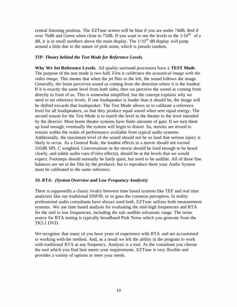
cancellation will show up as sharp dips in the frequency response and the node portion of the wave from Standing Waves will show up at lower frequency as sharp rises in frequency response. 1/12 is a general tool that gives us a first glimpse as to how the system is working and general trends. Make notes as to anything that is out of the ordinary for further consideration later in the test process. Your job at this stage is merely to think about whether it looks “normal”. If not, you need to consider what might be causing the unusual results. EXAMPLE- In an actual room the levels would be higher and typically we would measure the subwoofer and the LCR separately. The blue line is the cursor, which you can move with the left right arrow keys on your keyboard to see the level and frequency. As a general rule I run the pink noise around 75dB SPL when making these RTA measurements. There is nothing magic about that level; we just want to be above the noise floor so we are reading data. The SPL can be read on the blue thermometer style bar on the far left of the display.
If the above data was actual room data we would suspect that the sharp single spike at 40Hz was a room mode. We would then use the next step with 1/24th Octave to evaluate it.
14
c. Using 1/24th Octave Analysis- Subwoofers and Standing Waves. No area of home theater calibration creates more arguments among knowledgeable people than the issue of how to best handle low frequency energy (LFE). Some manufacturers say to put their subs in the corners to get approximately 6dB of additional energy from corner loading. Others say do not put subs in the corners as it creates poor modal density with resulting degradation in perceived frequency response at some seating locations. Acoustician Floyd Toole likes four subs arrayed like a Red Cross symbol at the mid points of the room for optimal modal density, while others like fractional positions. We have seen subs up on walls to “pressurize” the null on a height axis. Note: We are somewhat skeptical of the traditional and widely accepted explanation that subs pressurizing the null, and instead believe that you are simply energizing a higher order harmonic of the room modes, but either way it does seem to be effective. In the recording studio world subs typically in the front of the room and many consultants argue that the sound from subs can be localized in the frequency range above crossover. Remember that crossovers roll off the sound, they do not completely eliminate it. The correct answer is that each of these approaches is valid as a compromise for some specific problem. Your challenge is to find an approach that works for the room and equipment you have. Maximizing Performance with Sub-Woofers- a. The Myth of the Magic Subwoofer. Too often people try to do the impossible in the low frequency domain. All Subs are power hungry by nature of their size. And, as a result few systems have enough power to add EQ boost to a sub. Typically you need to almost double your amplifier output for every 3dB of boost. If your sub only goes down to 32Hz before it rolls off, and you want the bottom octave, the answer is a bigger Sub. Just because TEF tells you that the energy rolls off, does not mean that you can put it back. Boost with a Subwoofer is rarely viable. But there are other options. We know that some people will disagree with the following suggestions, and preface the comments with that they are general in nature. There is quite a bit of literature on the topic, and for an in depth understanding we refer you to the many fine papers that have been written. The following is just and overview of some real world thoughts. b. Corner Loading. You show up at the job site and find that the homeowner has just built a one zillion square foot home, the home theater is not dedicated and opens up to the grand foyer and the interior decorator helped the homeowner to pick out a tiny rosewood subwoofer which the homeowner really likes. Your advice that he will need a larger Subwoofer is hopeless and the best you can do in Test Mode is 69dB from the Sub. That is a case where one would consider finding a corner for a subwoofer. Placing the sub in a corner gives two hard boundaries to compress the energy back into the room. This may get you the 6dB to make 75dB reference. Frequency response at some seating areas may suffer, but chances are that you can work with data to find a compromise that gives you some additional bass.

15
c. The Bunker. At the opposite extreme are guys who build dedicated home theaters in their basements. The Walls are thick concrete. And, in the room you find that the owner wants several subs which were intended to be used by the government to explode landmines at a distance. You have racks of concert sized amplifiers to power the subwoofers and can easily create levels of bass suitable for a White Zombie concert. The problem is that the data shows that the energy is very uneven. Standing waves exist in all rooms, but in this environment they are piling up and creating 12dB variations from one seat to the next. The bass is lethal in the front seats and non-existent in the second row where the owner sits. This room would likely utilize an arrangement as suggested by Dr. Toole’s research with the cross pattern of four subs. d. Typical Rooms. ISO has created standards for typical home theaters. THX have researched average room acoustics. And, nearly all home theaters make assumptions as to the standard cubic volume and seating distances. These fortunately relate to most rooms we will work in, and in this environment you are looking for dense modal patterns without lone spikes. In this environment we typically measure/model the room modes and select a subwoofer position that is close as possible to the front of the room, and which gives the best response at the seats which are most important in the theater. If your seating locations have been modeled before you built the theater, you should get reasonable energy at every seat. If you placed one seat up against the rear concrete wall, well what did you expect? You will never fix the energy at that wall, although you will get a lot of bass at some frequencies. At some frequency you will find the node of a standing wave with enough energy to be a problem. That is the one you seek to minimize with subwoofer position, seating position and Equalization. e. Bass Traps. Bass traps are a generic term. In general the wavelength in the bass regions is too long to absorb. A 50Hz wave is 22’ long. Accordingly, traps tend to vibrate out of polarity with the wave to cancel energy. There are no magic bass traps that fix all problems. These are useful tools, but like a Phillips screwdriver it is for use with a Phillips screw. Read specs carefully to assure that you have the right trap for the problem you are seeking to solve. Making the Measurements. f. Noise Floor- The first measurement one needs to make is the ambient low frequency energy in the room with the audio and HVAC system on. This is different from NC. What we want to know is the low frequency noise floor so that we assure that we are looking at data and not noise. Attempts to equalize out the 30Hz rumble from the HVAC are comical at best. And, yet we see seemingly bright people do this all the time. Your TEF should be in 1/24th octave mode, and you simply sit quietly for several seconds in the room, with the mic at ear level at the central seating position and press the capture key to lock the data in as a trace on the EZTune screen. This is your noise line. Anything below that line is not data. g. Frequency Response. Using the broadband pink noise on the DVD, play it through a Subwoofer. All other loudspeakers should be off. If you have multiple subs, turn off the

16
other subs. Press Capture to freeze the response. Now turn on another Sub if the system has it, and measure just that sub. Compare the frequency response between the two subs. Is one better than the other. Now turn on both subs, and see the combined response, is that better than either of the subs individually. If the answer is no, then you can find a better position for at least one of the subs. You can also try other positions for the subs in the room to look for optimal subwoofer locations. And, to visualize how the room modes are changing the energy distribution (Room modes do not add energy, they just distribute it unevenly at some frequencies in all rooms), us the Modal Analysis Hot Key. h. Modal Analysis. If the room has solid boundaries i.e. sealed doors you can calculate the room modes with the Modal mode . The Modal mode has two types of displays, Graph and Chart. Graph shows the frequencies where each of the modes will be and splits the screen so that on top you can see the RTA display, and on the bottom you see an overlay of the modes. Clicking the cursor on a mode will light a blue cursor bar on the RTA screen above to show you the energy at that frequency. A rise of more than 3dB above the adjoining frequencies would be grounds to “consider” moving a subwoofer or a seating location. And a rise of 12dB is not uncommon from multiple modes. Every room has modes. What you are seeing to avoid is modes that stand out alone and have a node with a lot of energy directly at a seating position. You will be asked to type in the room dimensions, and by clicking the boxes you can elect to see all of the axial modes, Length, Width, Height, or you can see them individually. Each axis is differentiated by a color on the graph and there is a list of which is which in the information bar just above the graph. We rarely worry about the Tangential or Oblique modes, but if you want to go that deep, click on Chart mode to plot them in a numeric table. To switch to chart mode press the Modal Hot Key. Graph Mode of Axial Modes for Length and Width for a room 16’ x 25’
TIPS- Click on the colored mode bars to see a cursor at the frequency appear in the 1/24th octave display. NOTE- In the modal display only the Cursor function should be used. The rest of the keys, Group Delay, Sens, Phase have no function in this mode.
17
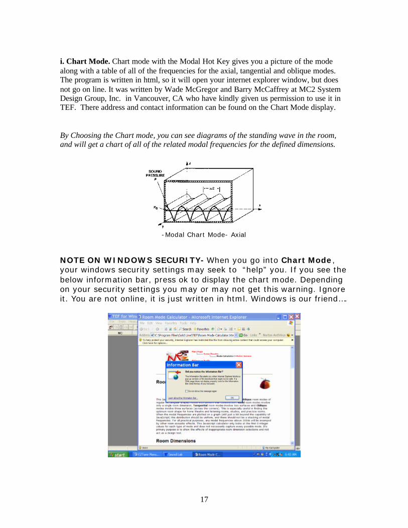
i. Chart Mode. Chart mode with the Modal Hot Key gives you a picture of the mode along with a table of all of the frequencies for the axial, tangential and oblique modes. The program is written in html, so it will open your internet explorer window, but does not go on line. It was written by Wade McGregor and Barry McCaffrey at MC2 System Design Group, Inc. in Vancouver, CA who have kindly given us permission to use it in TEF. There address and contact information can be found on the Chart Mode display. By Choosing the Chart mode, you can see diagrams of the standing wave in the room, and will get a chart of all of the related modal frequencies for the defined dimensions.
-Modal Chart Mode- Axial
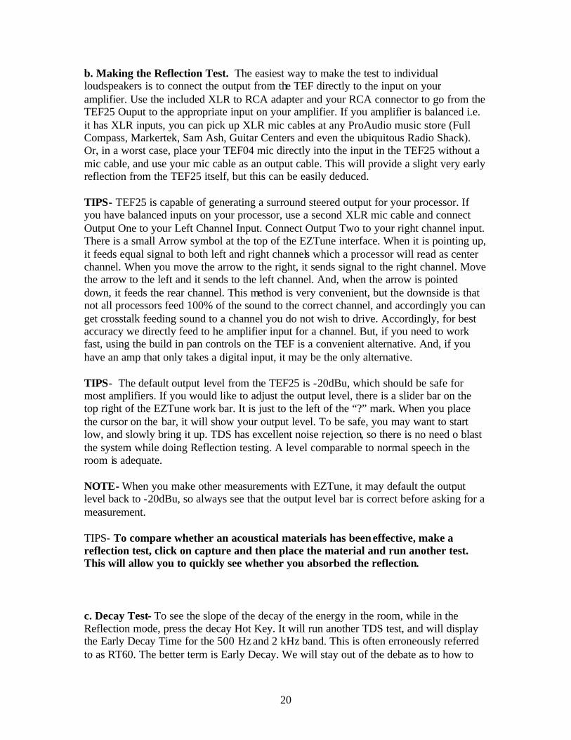
NOTE ON WINDOWS SECURITY- When you go into Chart Mode, your windows security settings may seek to “help” you. If you see the below information bar, press ok to display the chart mode. Depending on your security settings you may or may not get this warning. Ignore it. You are not online, it is just written in html. Windows is our friend….

18
j. 1/24th Octave Infrasonic Analysis is an area that is relatively new to Home Theater. The infrasonic range is the part of the acoustical spectrum that is below where we clearly hear sound, but where we can still detect the sound as rumble or vibration in the room. We have never seen a public statement on the use of infrasonics in move sound tracks. Of course to those who doubt/deny that such is done, we cordially invite such doubters to simply measure nearly any action movie with the 1//24th Octave analysis. Many loudspeakers are not effective at very low frequencies, but some are. We believe that the studios use infrasonics to create a sense of anticipation before the event such as an explosion or other action scene. And, if infrasonics raise adrenaline levels when used in a sound track, what do they do to people when they are unintentionally present in the room? HVAC systems that are out of balance are the worst offenders. And, in cities subways, big trucks and nearby highways can all induce high levels of infrasonic energy in a room. Our position is that ideally a home should have very low levels of ambient noise in the infrasonic range. An example of infrasonic energy in a house below 25 Hz.
The above data was caused by a truck driving down a road near the home. There is little we can do about that type of noise. The problem infrasonics we can fix would be those caused by out of balance HVAC and such.

19
11. Using the Reflection Hot Key- We all know the adage that the shortest distance between any two points is a straight line. We refer to this in the EZTune program as the “Initial Sound”. It came directly from the loudspeaker to the listener’s ear. a. Reflections are sound that arrived at the listener by any path longer than a straight line. A reflection is the same sound as the Initial Sound, which arrived after having bounced off of some surface in the room. Reflections are not per se bad for sound. If we had no reflections the sound would be like the inside of an anechoic chamber and would lack any spatial information. Your job as the consultant installer is to differentiate the late reflections which are essential to surround sound from the early reflections which can cause harmful cancellation and image shift. EZTune has automated this process by using Time Delay Spectrometry (TDS) to exactly measure the time when the sound arrives from the Initial Energy and then plotting it against the subsequent arrivals. These measurements are called Energy Time Curves (ETC), as they plot dB (Energy) over Ms (time in Milliseconds). Sound travels 1.13’ per millisecond. And, accordingly the curve shows both the time of arrivals and the distance for the path length traveled. EZTune then calculates the times and levels as against standards for good vs. bad reflections, and displays the harmful energy as “reflection” . When you click on a peak, it will identify whether it is a harmful reflection or “insignificant” if it is not. Those that are reflections should be corrected by placing an acoustical material at the point of where the reflection meets the surface. To find that point use a tape measure with the distance from the display. One side of the tape measure is placed against the loudspeaker; the other side is at the listener. Bending the tape, see what surface it can touch. The point where it can just touch at some midpoint in the tape, is your surface that caused the reflection. Some people also use a mirror from the seated position, to see where they can see the loudspeaker. Either method works, as angle of incidence equals angle of refection. Just like a pool ball on a pool table. Whatever angle it strikes a surface at; it will bounce back at an equal angle.
20
b. Making the Reflection Test. The easiest way to make the test to individual loudspeakers is to connect the output from the TEF directly to the input on your amplifier. Use the included XLR to RCA adapter and your RCA connector to go from the TEF25 Ouput to the appropriate input on your amplifier. If you amplifier is balanced i.e. it has XLR inputs, you can pick up XLR mic cables at any ProAudio music store (Full Compass, Markertek, Sam Ash, Guitar Centers and even the ubiquitous Radio Shack). Or, in a worst case, place your TEF04 mic directly into the input in the TEF25 without a mic cable, and use your mic cable as an output cable. This will provide a slight very early reflection from the TEF25 itself, but this can be easily deduced. TIPS- TEF25 is capable of generating a surround steered output for your processor. If you have balanced inputs on your processor, use a second XLR mic cable and connect Output One to your Left Channel Input. Connect Output Two to your right channel input. There is a small Arrow symbol at the top of the EZTune interface. When it is pointing up, it feeds equal signal to both left and right channels which a processor will read as center channel. When you move the arrow to the right, it sends signal to the right channel. Move the arrow to the left and it sends to the left channel. And, when the arrow is pointed down, it feeds the rear channel. This method is very convenient, but the downside is that not all processors feed 100% of the sound to the correct channel, and accordingly you can get crosstalk feeding sound to a channel you do not wish to drive. Accordingly, for best accuracy we directly feed to he amplifier input for a channel. But, if you need to work fast, using the build in pan controls on the TEF is a convenient alternative. And, if you have an amp that only takes a digital input, it may be the only alternative. TIPS- The default output level from the TEF25 is -20dBu, which should be safe for most amplifiers. If you would like to adjust the output level, there is a slider bar on the top right of the EZTune work bar. It is just to the left of the “?” mark. When you place the cursor on the bar, it will show your output level. To be safe, you may want to start low, and slowly bring it up. TDS has excellent noise rejection, so there is no need o blast the system while doing Reflection testing. A level comparable to normal speech in the room is adequate. NOTE- When you make other measurements with EZTune, it may default the output level back to -20dBu, so always see that the output level bar is correct before asking for a measurement.
TIPS- To compare whether an acoustical materials has been effective, make a reflection test, click on capture and then place the material and run another test. This will allow you to quickly see whether you absorbed the reflection.
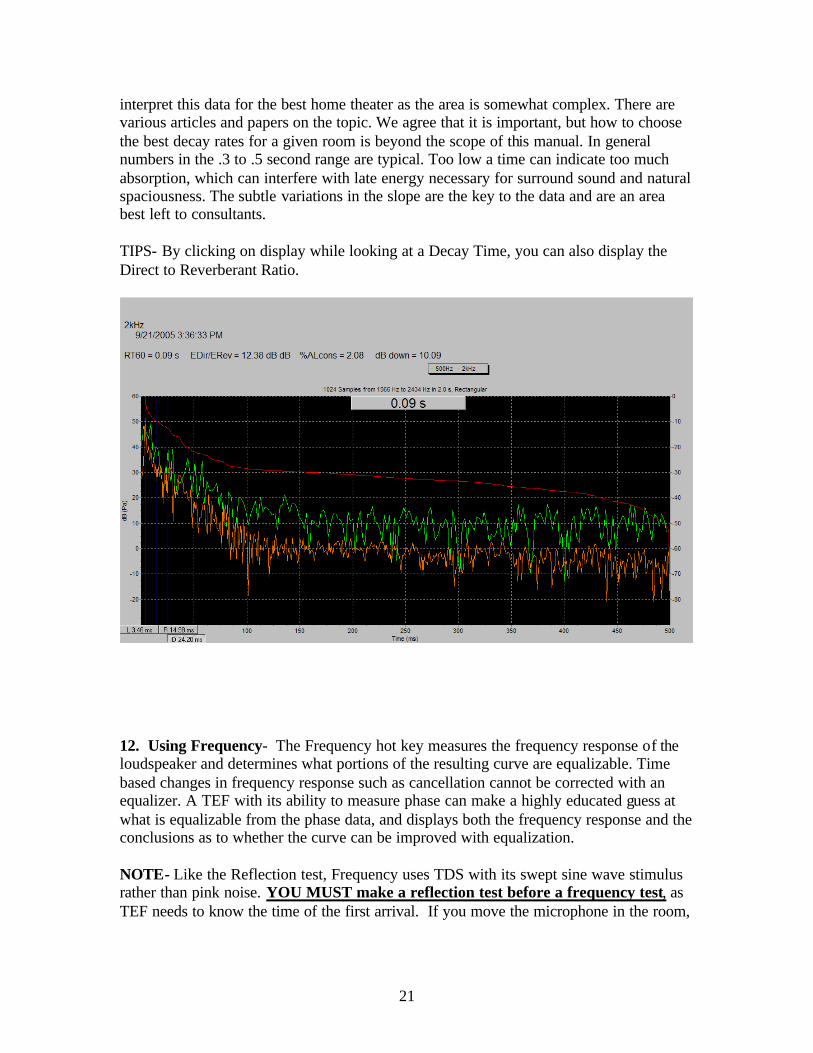
c. Decay Test- To see the slope of the decay of the energy in the room, while in the Reflection mode, press the decay Hot Key. It will run another TDS test, and will display the Early Decay Time for the 500 Hz and 2 kHz band. This is often erroneously referred to as RT60. The better term is Early Decay. We will stay out of the debate as to how to
21
interpret this data for the best home theater as the area is somewhat complex. There are various articles and papers on the topic. We agree that it is important, but how to choose the best decay rates for a given room is beyond the scope of this manual. In general numbers in the .3 to .5 second range are typical. Too low a time can indicate too much absorption, which can interfere with late energy necessary for surround sound and natural spaciousness. The subtle variations in the slope are the key to the data and are an area best left to consultants.
TIPS- By clicking on display while looking at a Decay Time, you can also display the Direct to Reverberant Ratio.
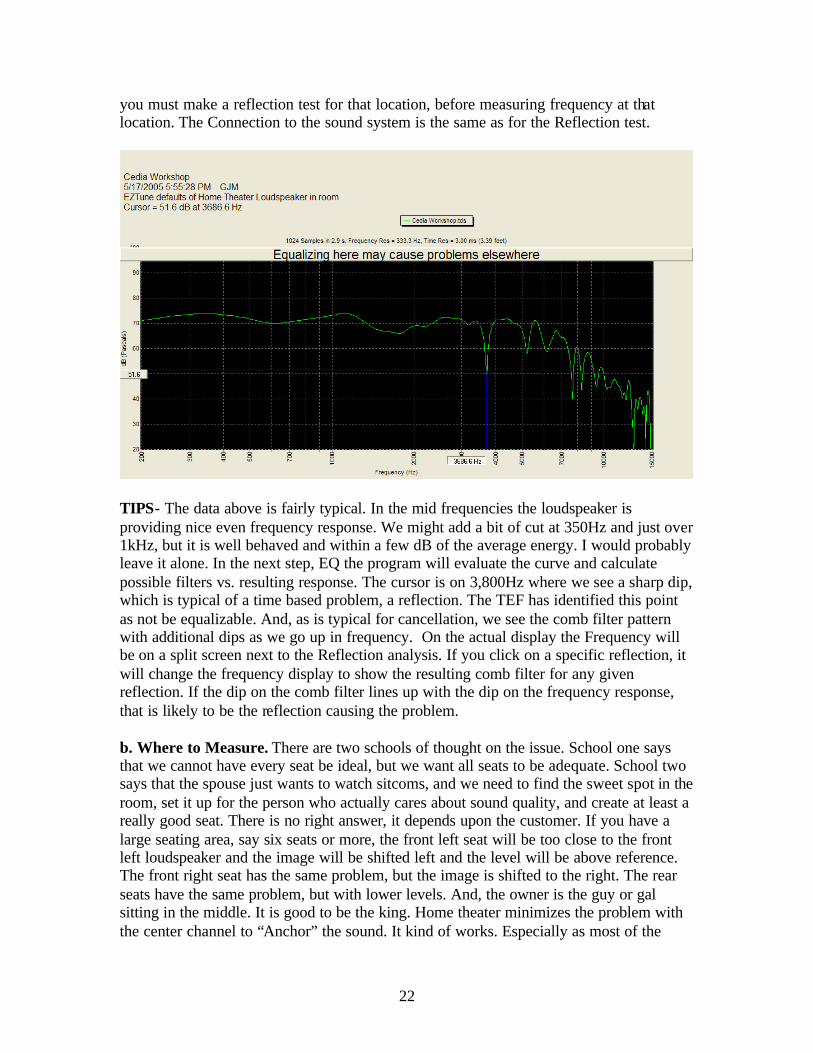
12. Using Frequency- The Frequency hot key measures the frequency response of the loudspeaker and determines what portions of the resulting curve are equalizable. Time based changes in frequency response such as cancellation cannot be corrected with an equalizer. A TEF with its ability to measure phase can make a highly educated guess at what is equalizable from the phase data, and displays both the frequency response and the conclusions as to whether the curve can be improved with equalization.
NOTE- Like the Reflection test, Frequency uses TDS with its swept sine wave stimulus rather than pink noise. YOU MUST make a reflection test before a frequency test, as TEF needs to know the time of the first arrival. If you move the microphone in the room,
22
you must make a reflection test for that location, before measuring frequency at that location. The Connection to the sound system is the same as for the Reflection test.
TIPS- The data above is fairly typical. In the mid frequencies the loudspeaker is providing nice even frequency response. We might add a bit of cut at 350Hz and just over 1kHz, but it is well behaved and within a few dB of the average energy. I would probably leave it alone. In the next step, EQ the program will evaluate the curve and calculate possible filters vs. resulting response. The cursor is on 3,800Hz where we see a sharp dip, which is typical of a time based problem, a reflection. The TEF has identified this point as not be equalizable. And, as is typical for cancellation, we see the comb filter pattern with additional dips as we go up in frequency. On the actual display the Frequency will be on a split screen next to the Reflection analysis. If you click on a specific reflection, it will change the frequency display to show the resulting comb filter for any given reflection. If the dip on the comb filter lines up with the dip on the frequency response, that is likely to be the reflection causing the problem.
b. Where to Measure. There are two schools of thought on the issue. School one says that we cannot have every seat be ideal, but we want all seats to be adequate. School two says that the spouse just wants to watch sitcoms, and we need to find the sweet spot in the room, set it up for the person who actually cares about sound quality, and create at least a really good seat. There is no right answer, it depends upon the customer. If you have a large seating area, say six seats or more, the front left seat will be too close to the front left loudspeaker and the image will be shifted left and the level will be above reference. The front right seat has the same problem, but the image is shifted to the right. The rear seats have the same problem, but with lower levels. And, the owner is the guy or gal sitting in the middle. It is good to be the king. Home theater minimizes the problem with the center channel to “Anchor” the sound. It kind of works. Especially as most of the
23
sound track comes out of the center loudspeaker. But, there will always be some compromise.
If you have a lot of seats, we recommend that you start with the center seat and optimize that position. Now measure the other seats and look at how they differ. If your wall treatments are effective and you chose your subwoofer locations well, you can now make subtle changes to the set up to minimize problems at other seats. Your job is to find the best compromise.
c. Mulitiplexing. If you want to multiplex with four mics, you need to do so with the RTA Module, not the Frequency module. There is no one right answer. Each method has strengths. Try it both ways in your theater, and pick the method that is most natural to your ears. You can always start from a multiplexed curve, and then use the Frequency module to evaluate whether a specific frequency problem is equalizable.
13. Aiming Loudspeakers. Most manufacturers will have a guide to how they suggest aiming their loudspeakers in the room. Depending on acoustical materials, lobing patterns from the loudspeakers and the directivity patterns of the loudspeakers, you can sometimes optimize sound by slight modifications in aiming. If standard changes are not working, try moving the loudspeakers both horizontally and vertically to see if improvements can be found. This is subtle and will require both analysis and a trained ear to find the optimum aim point for the LCR. With some loudspeakers the pattern is very smooth and little change will result. With other loudspeakers, including some very expensive loudspeakers, the results can be very very significant. If the loudspeaker is designed to be used vertically, did you place them horizontally, or vice versa? Such can result in the wide sound pattern found in some LCRs being directed at the ceiling and floor where they create reflections. High End Home Theater is complex.
14. Using EQ- After you have measured the Reflections and the Frequency, TEF can evaluate the phase angle and the magnitude vs. frequency data to select EQ filters and to display the optimal Frequency Center (Fc), Filter width (Q) and the ideal cut or boost (dB). In our automated features we limit to 6dB of boost and do not suggest EQ above 6000 Hz. If you want to modify these parameters, contact our Support department for information on changing the defaults. For 99% of all users, the defaults are well chosen.

24
15. Final Steps- After you have finished with all of the above steps, the last thing that you do is to re-set the Reference Levels. Get them as close to perfect as possible from the central seating position. Changes in loudspeaker aiming, EQ, room materials, etc will have slightly changed the Reference Levels. And, you are not done until the system has a well set reference level. Additionally, now is a good time to deal with any annoying buzzes or rattles that may have developed after a couple of hours of running some energy through the room. Used the DVD swept tones to run rattle sweeps. Use the pulsed tones to look for sound leaking out of the room. There is more information in the tutorial on the DVD. Use all the tools.

25
Conclusions- A sound system which does not sound good, is not good. Analysis will help you to understand why it does not sound good, but ultimately a well trained ear by an installation professional remains a vital component. There are hundreds of possible compromises to find that best set for a given room. Sit in every seat, listen to movies that you know well and which have a well mixed sound track. Is the speech clear and intelligible? Do the explosions rock you back in your chair? Are the maximum levels not painfully loud? Can you hear the quiet portions in the sound track? Can you close your eyes and point to exactly where the image is on the screen. The DVD has the Dolby Trailers, play them. The Egyptian trailer is a Subwoofer monster. Few subwoofers can handle it, but if yours can you are probably on track. And, finally home theater should create an emotional response from the listener. Your homeowner may be stone deaf, so listen to what he or she has to say. If he or she cannot hear the speech, adding a little boost in the 1 kHz region may make it easier for them to hear. In general women have better hearing at high frequency as the diameter of their ear canal is typically smaller. Listen to the women. Do they find the sound to treble? If so you may need to back down the EQ up past 2 kHz. You can have a couple of settings, which you have them listen to and tell you which one is best for them. If we all had perfect hearing, the measured response might be the ideal. But, your job is to create a system that is ideal for the listener. Do not be afraid to do what is necessary to create great sound. Use common sense, and we hope you enjoy your Gold Line analyzer.
FAQ 1. I pushed a button on the Interface and something odd happened, what should I do? EZTune is a series of automated configurations for the standard TEF software. If you press commands on the top tool bar it is possible to temporarily re-set some of these. Simply hit one of the EZTune hot keys and it should get you back to the defaults. Worse case, re-start the program. 2. Can I use the other TEF Functions? If you know how to run a TEF and want to use the parameter menus, simply go to TESTS, and press 5 to Restore Normal TEF Mode. To return to EZTune, restart the interface or Press 1 to return to EZTune.
26
3. Can I use other TEF software? TEF is TEF. Any windows TEF program will run on your TEF25. Want to do Polar ETC to measure the direction of origin for a reflection, MLS to do Maximum Length Sequence, NLA for Noise Level Analysis, Polar Plots for Directivity, Distortion measurements with SLX. Call us to purchase additional software packages. 4. Can I use a different microphone? TEF can be used with any quality microphone. To measure SPL you need to set the sensitivity in the Input/ Calibration menu at the top. If you will do this regularly, you need to modify the configuration file to remember these settings. Or, exit EZTune and use the Normal TEF mode and it will remember the settings. Feel free to call us for help with this issue. It is not difficult. 5. Is there a line level input- The input jacks on the TEF are combination XLR and ¼”. If you come in on the ¼” jack it is line level without phantom power. If you want to use the XLR jacks, click the yellow box next to mic to turn off the phantom power and click Input and Settings to turn off the preamp gain. 6. HELP! Customer support at Gold Line is available from ~9am to 5pm Monday to Friday Eastern Standard Time in the USA. For computer or general questions ask for Lou. If you have a question related to the home theater design, ask to speak to Greg. If your question is not an emergency, you can also e-mail us at [email protected] . 7. Do You Have Classes- We do run classes periodically. Contact us for dates, locations and times.
27
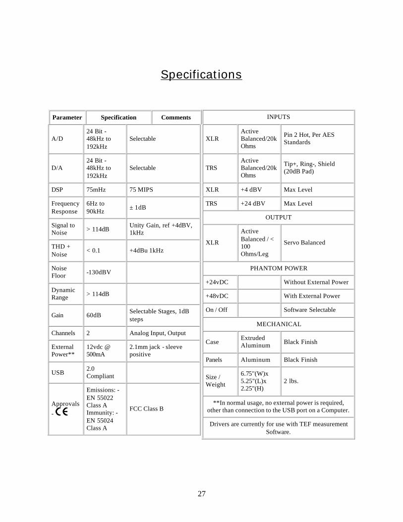
Specifications
Parameter Specification Comments
A/D 24 Bit - 48kHz to 192kHz
Selectable
D/A 24 Bit - 48kHz to 192kHz
Selectable
DSP 75mHz 75 MIPS
Frequency Response
6Hz to 90kHz
± 1dB
Signal to Noise > 114dB
Unity Gain, ref +4dBV, 1kHz
THD + Noise
< 0.1 +4dBu 1kHz
Noise Floor -130dBV
Dynamic Range > 114dB
Gain 60dB Selectable Stages, 1dB steps
Channels 2 Analog Input, Output
External Power**
12vdc @ 500mA
2.1mm jack - sleeve positive
USB 2.0 Compliant
Approvals
-
Emissions: - EN 55022 Class A Immunity: - EN 55024 Class A
FCC Class B
INPUTS
XLR Active Balanced/20k Ohms
Pin 2 Hot, Per AES Standards
TRS Active Balanced/20k Ohms
Tip+, Ring-, Shield (20dB Pad)
XLR +4 dBV Max Level
TRS +24 dBV Max Level
OUTPUT
XLR
Active Balanced / < 100 Ohms/Leg
Servo Balanced
PHANTOM POWER
+24vDC Without External Power
+48vDC With External Power
On / Off Software Selectable
MECHANICAL
Case Extruded Aluminum Black Finish
Panels Aluminum Black Finish
Size / Weight
6.75"(W)x 5.25"(L)x 2.25"(H)
2 lbs.
**In normal usage, no external power is required, other than connection to the USB port on a Computer.
Drivers are currently for use with TEF measurement Software.