eyeglass positional tracking using leap motion controller ... · technology to emulate monocular...
TRANSCRIPT
1
Abstract
Motion parallax is one of the most important 3D clues
for human vision perception. The majority of the 2D displays today display contents regardless of the user’s viewpoint. This project implements a system to track an user’s viewpoint position with respect to a laptop or desktop display using a Leap motion controller and small retro-reflective stickers that can be pasted on the user’s eyewear. 3D renderings can then be projected onto the display according to the user’s viewpoint to emulate a hologram effect. The Leap Motion controller and retro-reflective stickers allow for a considerably cheaper and vastly more portable system as compared to previous implementations with the Wii IR remote and the Microsoft Kinect. Experimentation during this project yielded unique insights to computer graphics techniques that are optimal for marker tracking in the stereo fisheye infrared camera system that the Leap Motion controller provides.
1. Introduction Human depth perception is primarily based on two visual cues: binary parallax and monocular movement parallax [1]. User interfaces that wish to recreate a 3D depth perception typically fall into two categories. Head mounted displays such as VR headsets that emulate both binary and monocular movement parallax [2,3,4]; and 3D gaming glasses in coordination with switching LCD screens that emulate binary parallax [5]. In recent years, there have been computer vision projects that use normal 2D LCD displays and head-tracking technology to emulate monocular movement parallax [6,7]. The monocular movement parallax provides the user with depth perception of any 3D model or environment. This depth perception can provide greater immersion in entertainment such as games and 3D movies. The ability to look around in the 3D environment can also provide better user experience for CAD tools.
This project implements a system that is cheap (sub $100) and portable (can be integrated into laptops) that allows for capturing the 3D position of a user’s viewpoint with respect to a device’s display. This information can be used for 3D perspective rendering or other uses. The work in this project involves both the design of a 3D position capture system on the Leap Motion controller and also the exploration of existing computer vision techniques at subsystems to determine the best techniques in the unique image capture space that the Leap Motion controller provides.
2. Overview
2.1. Previous Work
Johnny Lee’s Wii based head tracking and parallax perspective generation demo [6] proves that monocular movement parallax can produce dramatic depth perception using 2D displays. Since Johnny Lee’s project, others have tried to simplify the head tracking hardware. Microsoft Kinect based head tracking [7] has shown to work well. The only portable implementations of parallax projection based on user viewpoint utilize a webcam and computer vision algorithms to perform head-tracking [8,9]. However, these systems do not have depth information and assume that the users viewpoint moves along a 2D plane at a certain distance from the display. Furthermore, head rotations in any direction are unaccounted for. This leads to inaccuracies that affect the perspective projection.
2.2. Contributions
In this project, I used the Leap Motion controller [10] and retro-reflective stickers that can be pasted on a user’s eyewear to provide the 3D position of the users viewpoint with respect to a laptop or desktop display. This viewpoint information can be used to create perspective projections of 3D models that give the user an illusion of depth and also enable the user to explore 3D environments by moving their head. Since the information captured in this
Eyeglass positional tracking using leap motion controller for parallax projection
Rajarshi Roy
Stanford University [email protected]
2
system provides the 3D position of each eye, separate renderings from each eye’s viewpoint can be combined in viewed via red-blue 3D glasses or shutter based 3D glasses such as the NVIDIA 3D Vision 2 [5] to provide complete depth perception at a portable level. The previous implementations of such a system using the Wii [6] and the Kinect [7] controllers relied on specialized depth-capture technologies that these controllers provide readily. The Leap Motion controller provides images from stereo IR cameras. Thus, the 3D position capture of the user’s eyewear was entirely performed through 2D computer vision techniques. The focus of this project was to explore various techniques in order to optimize a robust tracking system for the Leap Motion. As a result, future projects that use the Leap Motion controller for similar uses may benefit from the results of this project. A basic perspective rendering was also implemented as a proof of concept.
3. Technical Approach
3.1. Summary
The Leap Motion Camera Images API [11] allows access to the raw camera images from the leap motion controller. Two 640*240 pixel greyscale images corresponding to the left and right cameras (Figure 1) captured in the infrared spectrum are available at a tested framerate of 10 frames per second.
Figure 1. In order to obtain the 3D eye position of the user from this image stream, the following steps were taken: 1) Marker detection: From each of the stereo images, a reliable marker has to be detected that correspond to the 2D projection from a fixed position on the user’s eyewear
onto each of the Leap Motions’s cameras. There may be false positives (detection of unrelated features as markers) and false negatives (inability to detect marker). Various techniques were evaluated at this subsystem 2) Marker rectification: The Leap Motion API can rectify the 2D marker position detected from the previous step to a standardized perspective projection system. The individual Leap Motion controller has a calibration step during installation that allows this. The rectification handles the correction of the fisheye lens effects, and misalignments of camera. The reason that the rectification of the entire input image is not performed before the marker detection step is due to performance and will be discussed in greater detail later. 3) Marker correspondence: Markers detected from the left camera image have to be correlated to markers detected from the right camera image. Again, various techniques were evaluated at this subsystem. At this stage false correlations across markers can occur even if the correct markers were detected. 4) Triangulation: The 2D image plane location of corresponding marker pairs from the previous step can now be used to triangulate to the 3D position of the markers. Properties of the rectified camera system provided in the Leap Motion documentation in conjunction with manually measured real-world values are used in this step. 5) Noise removal: Falsely detected markers are removed in this step. Undetected markers could be approximated in this step (not implemented but will be discussed). Also, since the input images ultimately have low resolutions, even correctly detected marker positions are prone to noise. Some techniques to filter this noise will be discussed. The output after the last step provides the 3D position and orientation (multiple markers) of the eyewear (and thus user’s eyes) with respect to the leap motion controller. This position can be translated to be with respect to the display based on real-world measured values of how the controller is mounted. Finally, a proof-of-concept render can be implemented to show parallax projection based on the user’s viewpoint.
3.2. Methodology
Since the objective is to capture the 3D position of the user’s eyes, its can be seen from Figure 2 that the 3D position of at least two markers: Maker R and Marker L are needed. Then the user’s eye positions can be

3
approximated to lie on the 3D line (Line A) that joins the two markers. If only one marker was tracked, any rotation about marker would cause the eye positions to be ambiguous. Another possible design of the system that was not pursued is three or more coplanar markers. That would allow flexibility to place the markers outside the virtual line connecting the user’s eyes.
Figure 2. Looking at Figure 1, we can see that there are no base distinctive features in the IR spectrum that can be tracked as markers. Thus, an artificial marker was needed for tracking. After experimentation with different materials, 3MTM ScotchliteTM retro-reflective tape produced the brightest markers which were the most consistent at different angles. Figure 3 shows raw camera images of user with eyewear that has the retroreflective markers.
Figure 3. The markers were 7mm circles punched out from the retro-reflective tape and stuck on the eyewear as shown in Figure 4.
Figure 4. The Leap Motion controller was mounted in front of the webcam of the user’s MacBook Air laptop as shown in Figure 5.
Figure 5. With a reliable marker and a standardized experimental setup, the steps outlined in the summary were experimented upon. The following sections will describe techniques tried in each subsystem along with benchmark results and analysis. Section 4: Experimental Results will thus be a summary of the experimentation described in the following sections. Since this project was a single person project with little background work in the Leap Motion infrastructure to refer from, rapid experimentation, prototyping and visual feedback was required. Thus the Java based Processing IDE [15] was chosen as the infrastructure of choice. The Processing IDE allows for quick real-time visualization and rendering. The OpenCV Java bindings [16] were imported in Processing and a wrapper library for the Leap Motion Java bindings [17] was used. 3.2.1 Benchmarking The ideal benchmarking for all of the subsystems would be a benchmark that compares the actual position of the 3D markers with the captured position of the 3D markers. However, a method to calculate the actual position of the

4
3D markers would need accelerometers and thus was not possible. As a result, two benchmarking methods were used. The first method was qualitative visual feedback where a basic 3D model of the setup and marker positions was rendered as spheres. The second benchmarking method, which was crucial in comparing and optimizing techniques, was the “fraction of time real-world constraints met” or the “FTRWCM score”. This is a loose benchmark, which is not based on any existing benchmarks. To calculate the FTRWCM score, the user moves around in front of the experimental setup with the eyewear on for a minute. The score is the fraction of time that the following constraints are met after all the calculation steps: 1) The 3D position of both a left and a right marker is produced 2) Left marker is to the left (smaller x coordinate) than right marker 3) Both left and right markers are within a bounding volume (within 2ft on each side, within 2ft on top and bottom, and within 3ft depth from the leap motion controller) 4) The measured distance between the 3D position of left and right marker are within 5% of actual distance between left and right markers. 3.2.2 Marker Detection The first method that was attempted for marker detection was image thresholding and contour detection. Since the marker color as seen in Figure 3 is close to white, the idea was to apply a threshold on the image so that pixels with intensity values above the threshold become white and all other pixel become black. The org.opencv.imgproc.Imgproc.threshold() function was used for this. The next step was to use the org.opencv.imgproc.Imgproc.findContours() function to get a list of all the blobs of white pixels. Finally, a constraint on the maximum area of blobs was used to filter out large sections of white pixels. This method did not work well (Table 4.1) for a range of thresholds tried. At high thresholds, the marker would not be detected if its brightness value fell below a certain level. At lower thresholds, the marker would merge with other blobs of above-threshold pixels. The second method was to use Hough voting to detect circles in the image since the markers were circular. The org.opencv.imgproc.Imgproc.HoughCircles() function with the CV.HOUGH_GRADIENT vote was used to detect the marker in the image. This method worked better than the thresholding and contour detection (Table 4.1) method. However, the performance was not robust since the markers were not detected when the projected shape of
the marker became ellipsoid due to the angle of the eyewear of the severe fisheye distortion in the image. The third method evaluated was the OpenCV FeatureDetector.SIMPLEBLOB detector. This detector is essentially a sophisticated version of the threshold+contour method. The default SIMPLEBLOB detector parameters threshold the image at 10 levels instead of a single threshold. After finding contours it also conducts modes by area, circularity, inertia (eccentricity) and convexity of blobs in order to detect simple circular dark blobs. The raw image was thus inverted and the default SIMPLEBLOB detector was applied. The results can be seen in Figure 6 where yellow dots show detected markers. Even though there were many false positives, the actual markers were always tracked. This led to better results (Table 4.1).
Figure 6. Finally, the default parameters of the SIMPLEBLOB detector (See Appendix A) were tuned (See Appendix B) to reduce false positives. The results can be seen in Figure 7.
Figure 7. This method had the highest FTRWCM score among all the marker detector methods and was used in the final implementation.

5
3.2.3 Marker Rectification Since the Leap Motion controller cameras have high fisheye distortion since they high field-of-view lenses. Furthermore, the cameras may be slightly misaligned. As a result, it is not possible to triangulate 3D position directly from the 2D marker positions detected in the raw images. Fortunately, after calibrating the Leap Motion controller with provided software, the com.leapmotion.leap.Image.rectify() function in the Leap Motion API can be used to rectify the 2D marker positions in the left and right image. The rectification can be verified from Figure 8, which shows that the rectified marker positions follow the epipolar constraint of having the same vertical coordinate.
Figure 8. Bottom left corner show rectangles around corresponding markers yielding to epipolar constraint One alternate method could have been to rectify the entire raw images before marker detection. This method was slow and took more than a second to process one frame. Thus this method was not used. 3.2.4 Marker Correspondence Before triangulation can be performed, rectified markers from the left and right camera images have to be correlated into pairs. Several methods were evaluated to perform marker correspondence. The first method that was attempted was to simply declare the pair of leftmost marker (smallest x coordinate) in each of the camera image to be correlated to the left marker. The rightmost marker (largest x coordinate) in each image was similarly correlated to the right marker. This method did not perform well (Table 4.1) under the presence of infrared sources such as incandescent bulbs. This method worked better in complete darkness (Table 4.1) but not perfectly, as false positive markers from previous steps would break the logic.
The second method attempted was to use SURF descriptors at markers to correlate them. The SURF type OpenCV DescriptorExtractor (org.opencv.features2d.DescriptorExtractor) was used to extract SURF feature vectors at from the left and right raw images at the marker positions. Then the FLANNBASED OpenCV DescriptorMatcher was used to correlate the markers with the closest matching SURF feature vectors. Even though this method can be very effective in correlating images captured in the visible light spectrum [18], the method did not work well in the infrared images. This could be due to the lack of textures around markers in infrared spectrum. The correlations were inaccurate (Figure 9) and the performance was not low (Table 4.1).
Figure 9. The third method used SIFT features instead of SURF features to correlate markers. This method worked marginally better (Table 4.1) and still had similar issues to the SURF based method as seen in Figure 10.
Figure 10. The final correlation method evaluated was epipolar constrain based. Since from Figure 8 it was observed that corresponding markers follow the epipolar constrain of horizontally rectified images, which is that their vertical coordinates will be the same. Thus the correlation method used was that ===================================== for (rectified marker l in left image) for(rectified marker r in right image) if r falls in constrain rectangle of l, consider (l,r) as a pair =====================================
6
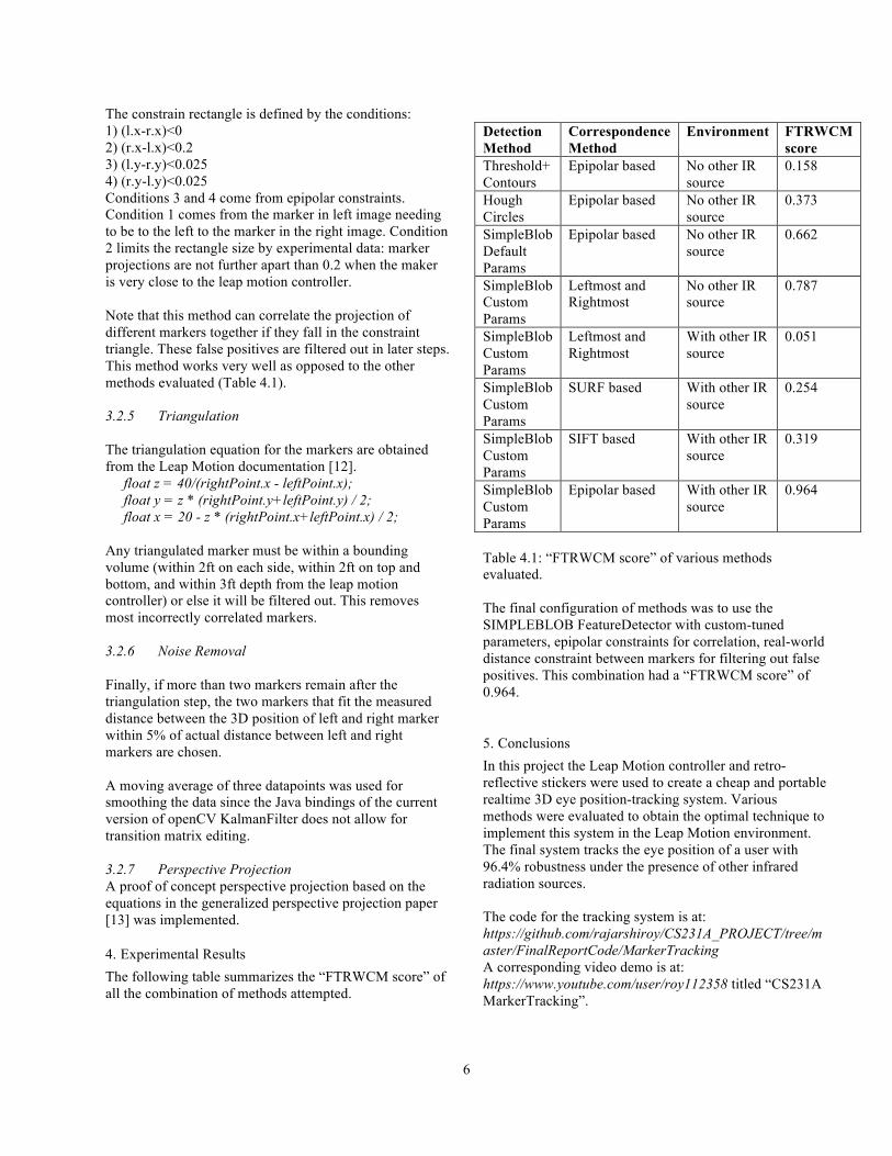
The constrain rectangle is defined by the conditions: 1) (l.x-r.x)<0 2) (r.x-l.x)<0.2 3) (l.y-r.y)<0.025 4) (r.y-l.y)<0.025 Conditions 3 and 4 come from epipolar constraints. Condition 1 comes from the marker in left image needing to be to the left to the marker in the right image. Condition 2 limits the rectangle size by experimental data: marker projections are not further apart than 0.2 when the maker is very close to the leap motion controller. Note that this method can correlate the projection of different markers together if they fall in the constraint triangle. These false positives are filtered out in later steps. This method works very well as opposed to the other methods evaluated (Table 4.1). 3.2.5 Triangulation The triangulation equation for the markers are obtained from the Leap Motion documentation [12]. float z = 40/(rightPoint.x - leftPoint.x); float y = z * (rightPoint.y+leftPoint.y) / 2; float x = 20 - z * (rightPoint.x+leftPoint.x) / 2; Any triangulated marker must be within a bounding volume (within 2ft on each side, within 2ft on top and bottom, and within 3ft depth from the leap motion controller) or else it will be filtered out. This removes most incorrectly correlated markers. 3.2.6 Noise Removal Finally, if more than two markers remain after the triangulation step, the two markers that fit the measured distance between the 3D position of left and right marker within 5% of actual distance between left and right markers are chosen. A moving average of three datapoints was used for smoothing the data since the Java bindings of the current version of openCV KalmanFilter does not allow for transition matrix editing. 3.2.7 Perspective Projection A proof of concept perspective projection based on the equations in the generalized perspective projection paper [13] was implemented.
4. Experimental Results The following table summarizes the “FTRWCM score” of all the combination of methods attempted.
Detection Method
Correspondence Method
Environment FTRWCM score
Threshold+ Contours
Epipolar based No other IR source
0.158
Hough Circles
Epipolar based No other IR source
0.373
SimpleBlob Default Params
Epipolar based No other IR source
0.662
SimpleBlob Custom Params
Leftmost and Rightmost
No other IR source
0.787
SimpleBlob Custom Params
Leftmost and Rightmost
With other IR source
0.051
SimpleBlob Custom Params
SURF based With other IR source
0.254
SimpleBlob Custom Params
SIFT based With other IR source
0.319
SimpleBlob Custom Params
Epipolar based With other IR source
0.964
Table 4.1: “FTRWCM score” of various methods evaluated. The final configuration of methods was to use the SIMPLEBLOB FeatureDetector with custom-tuned parameters, epipolar constraints for correlation, real-world distance constraint between markers for filtering out false positives. This combination had a “FTRWCM score” of 0.964.
5. Conclusions In this project the Leap Motion controller and retro-reflective stickers were used to create a cheap and portable realtime 3D eye position-tracking system. Various methods were evaluated to obtain the optimal technique to implement this system in the Leap Motion environment. The final system tracks the eye position of a user with 96.4% robustness under the presence of other infrared radiation sources. The code for the tracking system is at: https://github.com/rajarshiroy/CS231A_PROJECT/tree/master/FinalReportCode/MarkerTracking A corresponding video demo is at: https://www.youtube.com/user/roy112358 titled “CS231A MarkerTracking”.

7
A proof-of-concept perspective rendering using tracking data was also implemented. The code for the system is at: https://github.com/rajarshiroy/CS231A_PROJECT/tree/master/FinalReportCode/PerspectiveRender A corresponding video demo is at: https://www.youtube.com/user/roy112358 titled “CS231A PerspectiveRender”. In the future, a more extensive rendering system can be developed. Also, the tracking accuracy can be further improved using Extended Kalman Filtering and Optical Flow based prediction. The framerate of the system is 10 frames per second on a Macbook Air. This could by improved via multithreading the image acquisition and tracking.
6. References [1] Depth Cues in the Human Visual System. Marko Teittinen. <http://www.hitl.washington.edu/projects/knowledge_base/virtual-worlds/EVE/III.A.1.c.DepthCues.html> [2] Google Cardboard. <https://www.google.com/get/cardboard/> [3] Oculus Rift. <https://www.oculus.com/en-us/> [4] HTC Vive. <https://www.htcvive.com/us/> [5] 3D Vision 2 Wireless Glasses. <http://www.nvidia.com/object/product-geforce-3d-vision2-wireless-glasses-us.html> [6] Head Tracking for Desktop VR Displays using the Wii Remote. Johnny Lee. <http://johnnylee.net/projects/wii/> [7] 3D Display Simulation using Head-Tracking with Kinect. Manfred Zabarauskas. http://blog.manfredas.com/3d-display-simulation-using-head-tracking-with-microsoft-kinect/ [8] Head Tracking Motion Parallax. <http://blog.onthewings.net/2012/03/04/head-tracking-motion-parallax-3d-in-haxe-flash/> [9] Improving 3D perception by adding eye-tracking based motion parallax. <http://research.microsoft.com/pubs/147007/Mono3DdemoICASSP09b.pdf> [10] Leap Motion Controller. <http://blog.leapmotion.com/hardware-to-software-how-does-the-leap-motion-controller-work/> [11] OpenCV Blob detection library. <http://docs.opencv.org/trunk/d0/d7a/classcv_1_1SimpleBlobDetector.html#gsc.tab=0> [12] Image API Basics. Leap Motion developer documentation. <https://developer.leapmotion.com/documentation/csharp/devguide/Leap_Images.html> [13] Generalized Perspective Projection. Robert Kooima. <http://csc.lsu.edu/~kooima/pdfs/gen-perspective.pdf>
[14] 3M™ Scotchlite™ Reflective Material. <http://solutions.3m.com/wps/portal/3M/en_US/ScotchliteNA/Scotchlite/> [15] Processing IDE. <https://processing.org/reference/environment/> [16] OpenCV Java Bindings. <http://docs.opencv.org/java/2.4.9/> [17] Leap Motion Wrapper Library. <https://github.com/nok/leap-motion-processing> [18] Feature Matching with FLANN. <http://docs.opencv.org/2.4/doc/tutorials/features2d/feature_flann_matcher/feature_flann_matcher.html>

8
6. Appendix Appendix A: OpenCV SIMPLEBLOB Default Parameters: %YAML:1.0 thresholdStep: 10. minThreshold: 50. maxThreshold: 220. minRepeatability: 2 minDistBetweenBlobs: 10. filterByColor: 1 blobColor: 0 filterByArea: 1 minArea: 25. maxArea: 5000. filterByCircularity: 0 minCircularity: 8.0000001192092896e-01 maxCircularity: 3.4028234663852886e+38 filterByInertia: 1 minInertiaRatio: 1.0000000149011612e-01 maxInertiaRatio: 3.4028234663852886e+38 filterByConvexity: 1 minConvexity: 9.4999998807907104e-01 maxConvexity: 3.4028234663852886e+38 Appendix B: OpenCV SIMPLEBLOB Custom Parameters: %YAML:1.0 thresholdStep: 5. minThreshold: 55. maxThreshold: 255. minRepeatability: 2 minDistBetweenBlobs: 10. filterByColor: 1 blobColor: 255 filterByArea: 1 minArea: 5. maxArea: 20. filterByCircularity: 0 minCircularity: 8.0000001192092896e-01 maxCircularity: 3.4028234663852886e+38 filterByInertia: 1 minInertiaRatio: 1.0000000149011612e-01 maxInertiaRatio: 3.4028234663852886e+38 filterByConvexity: 1 minConvexity: 9.4999998807907104e-01 maxConvexity: 3.4028234663852886e+38