eye gaze correction with a single webcam based on …mturk/pubs/qinisvc2015.pdfapply laplacian...
TRANSCRIPT
Eye Gaze Correction with a Single WebcamBased on Eye-Replacement
Yalun Qin, Kuo-Chin Lien, Matthew Turk, Tobias Hollerer
University of California, Santa Barbara
Abstract. In traditional video conferencing systems, it is impossible forusers to have eye contact when looking at the conversation partner’s facedisplayed on the screen, due to the disparity between the locations of thecamera and the screen. In this work, we implemented a gaze correctionsystem that can automatically maintain eye contact by replacing theeyes of the user with the direct looking eyes (looking directly into thecamera) captured in the initialization stage. Our real-time system hasgood robustness against different lighting conditions and head poses,and it provides visually convincing and natural results while relying onlyon a single webcam that can be positioned almost anywhere around thescreen.
1 Introduction
With the introduction of both consumer and enterprise video communicationtechnologies, videoconferencing is becoming more and more widely used, allow-ing people in different locations to meet face-to-face with each other withouthaving to travel to a common location. However, most current videoconferenc-ing systems are not able to maintain eye contact between the conversation par-ticipants due to the disparity between the locations of the videoconferencingwindow and the camera. This problem has been addressed in some high-endlevel videoconferencing systems by using special hardware, such as semitrans-parent mirrors/screens [1, 2], cameras with depth sensors [3, 4], or stereo cameras[5, 6]. However due to the extra hardware dependence, these solutions cannot beapplied to consumer level videoconferencing systems, which typically only usewebcams.
In this paper, we present a gaze correction system that relies only on asingle webcam, and thus can be integrated in current videoconferencing systemsrunning on various consumer level devices, ranging from desktop computers tosmartphones. Our system corrects the gaze by replacing the eyes of a person inthe video with images of eyes looking directly at the camera; these are capturedduring an initialization session. By further applying several computer visionand computer graphics techniques we make the result look very natural undera range of lighting conditions and head poses. The system supports camerasplaced above, below, or to either side of the display screen. The speed of oursystem is about 30 fps on 640 × 480 streams from a laptop camera. With minorchanges this approach can be easily extended to correct the gaze of multipleusers simultaneously.
G. Bebis et al. (Eds.): ISVC 2015, Part I, LNCS 9474, pp. 599–609, 2015.DOI: 10.1007/978-3-319-27857-5 54Springer International Publishing Switzerland 2015
2 Related Work
Previous research using a single webcam for gaze correction has taken two mainapproaches. The first category of approaches aims to perform the gaze correctionby synthesizing a new view of the user’s face from a virtual point behind thescreen in the center, which is equivalent to performing a rotation of head/faceor the entire image by some degrees [7–11]. However these approaches exhibitdistortions on the contour of the head, occluded areas and glasses frames. Inaddition, most of these methods do not perform any explicit changes in theshapes of the eyes, which we believe is very critical to gaze correction and mightnot be modified sufficiently by merely rotating the head model.
The second category of approaches performs gaze correction by only pro-cessing the eyes [12–16]. Most of these methods aim to reposition the iris usingcomputer vision techniques like segmenting and warping [12–14], which all suffersome robustness issues under various lighting conditions and do not have verysatisfactory real-time performance. The eye-replacement method proposed byWolf et al. [15] can establish very natural looking eye contact and is quite robustunder various lighting conditions; however due to the quality of the tracker, theirsystem will fail to work when there are large head motions. Their method is alsounable to detect whether the user is looking sideways or not and simply replacesthe eyes regardless of the actual gaze direction. A recent approach proposed byKononenko et al. [16] aims to synthesize eyes looking up just by modifying theoriginal image, which turns out to have a good real-time performance, and theresult looks natural even when the user is looking sideways. However, due to thelimitation of training data, the system only supports vertical gaze redirection by10 to 15 degrees.
3 Eye-Gaze Correction Method
3.1 System Overview
Our work is based on the eye-replacement method proposed by Wolf et al. [15].We improved it to make it more robust to changes in lighting conditions andhead poses. In contrast to Wolf’s approach, ours does not require training andthe quick initialization could potentially be done automatically. To ensure theresults look good, we also defined the zone of correction, which is the range ofhead poses and eye openness when the gaze correction should be applied. Wemade the results look natural not only inside the zone but also in the transitionareas between inside the zone of correction and outside. Ideally the actual gazedirection should also be taken into account, so that gaze correction is performedonly when the user is looking at the video participant. We further extended oursystem to support the case when the camera is positioned lateral to the screen.
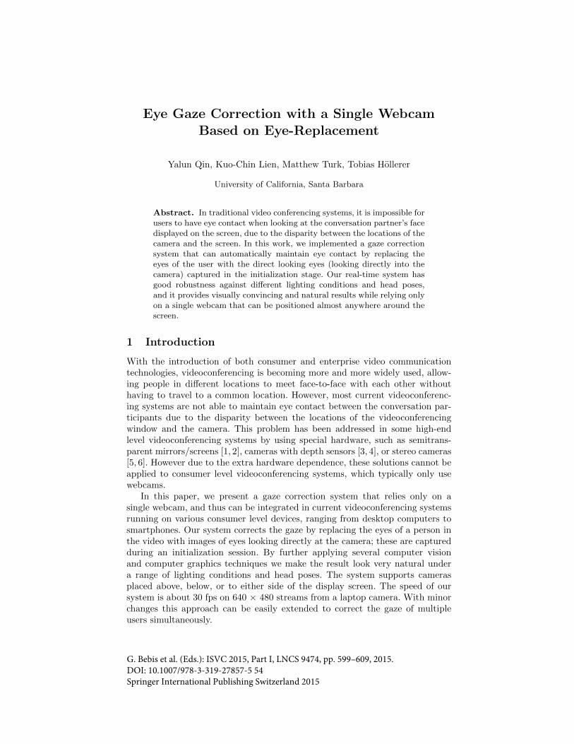
Our system consists of two stages (Fig. 1):
1. Initialization stage, in which the user is asked to look at the screen first(thisstep is used for setting the ratio of vertical eye enlargement, which is detailed
Fig. 1. Work flow of our system
in Section 3.3) and then look straight at the camera. The system capturesa pair of eyes that are looking at the camera, used for replacement. Eyecontact detection method like [17] can be applied in this stage to make thecapture of direct looking eyes more automatic.
2. Videoconferencing stage, in which the user’s eyes are tracked and the pre-vious captured eyes are warped and pasted on the original eyes. Reillumi-nation, blending and morphing techniques are then applied to improve thegaze correction results, which are displayed in real time.
Our system is implemented in C++ using OpenCV and OpenGL libraries.
3.2 Face Tracking
The face tracker used in our work is the IntraFace tracker [18]. As is shown inFig. 2, the IntraFace tracker outputs 49 facial feature points in total, of whichthe 12 eye points are used by our system. We compute the bounding rotated boxfor each eye, and enlarge the width of it with a scale factor 3.5 and the height ofit with a scale factor 2 to create the bounding rotated box of the eye patch. Theareas within the outer rotated rectangles are what we refer as “eye patches”.The purpose of this enlargement step is to make sure the pasted eyes completelycover the original eyes. The two rectangles also define the area iterated in thereillumination step, which will be explained in Section 3.3. The two scale factorsare selected through experimentation to achieve the best visual result.
3.3 Eye Replacement
Warping and pasting of eyes In order to replace the eyes with the direct look-ing ones captured in the initialization stage, we need to first warp the captured

eyes so that they have similar shapes to the original eyes, which we approximateby an affine transformation. To achieve this we use four pairs of points (four cor-ners of the enlarged bounding rotated box) in the source image and destinationimage to establish the mapping. Note that in the destination image we enlargethe eyes by some ratio in the vertical direction if the gaze direction needs to becorrected vertically, which is equal to the ratio of width of the direct lookingeyes to the width of the eyes looking at the screen. The enlargement step isimportant to make sure the direct looking eyes look real after warping.
Reillumination The pasted eyes look very unnatural due to the fixed illu-mination of the pasted eye images. Ideally the illumination of the pasted eyepatches should be very similar to the original eye patches, changing with the ac-tual lighting condition. We use Wolf’s [15] reillumination method due to its lowcomputational complexity and good results. The idea is that assuming the user’sface is Lambertian, then the intensity of a pixel in each of the RGB channels canbe approximated using a third order polynomial [19, 20]. Unlike Wolf’s method,we do not iterate through every pixel in the eye patch. Instead, we only iteratethrough the pixels that are in between the original rotated bounding box andthe enlarged one (the area between the two rectangles around each eye in Fig. 2).This is because we found that the pixel intensities in the eye area introduce some
Fig. 2. Face and eye tracking result. The dots represent the feature points returned bythe IntraFace tracker. Inner rectangles around the eyes are the rotated rectangles of theminimum area enclosing the eye points. Outer rectangles are the enlarged rectangles.The coordinate system at the top left represents the head pose direction.
(a) (b) (c) (d)
Fig. 3. Comparison of intermediate results: (a) original uncorrected eyes, (b) pastedeyes without any adjustment, (c) reilluminated eyes, (d) final result after Laplacianblending

(a) Originaleye image
(b) Pastedeye image
(c) Mask (d) Blendedeye image
Fig. 4. Input and output of Laplacian pyramid blending
unwanted noise to the solution, which as a result makes the reilluminated eyeimage noisy, having some unwanted slim shadows in the eyes. The reilluminatedresult is shown in Fig. 3(c).
Laplacian pyramid blending After reillumination, the contrast between thepasted eye patch and the surrounding area is greatly reduced. However the borderof the eye patch is still noticeable (Fig. 4(b)). To smooth these artifacts out, weapply Laplacian pyramid blending on the eye images, which is a simple andefficient algorithm to blend one image seamlessly into another [21].
3.4 Smoothing of Transition
Due to the limitation of the face tracker, face tracking fails for some head poses.And since our eye-replacement method doesn’t work well when the rotation angleof the user’s head is too large, it is necessary to define a zone of correction sothat gaze correction is performed only when both processes work. Specifically,the zone of correction is defined as follows:
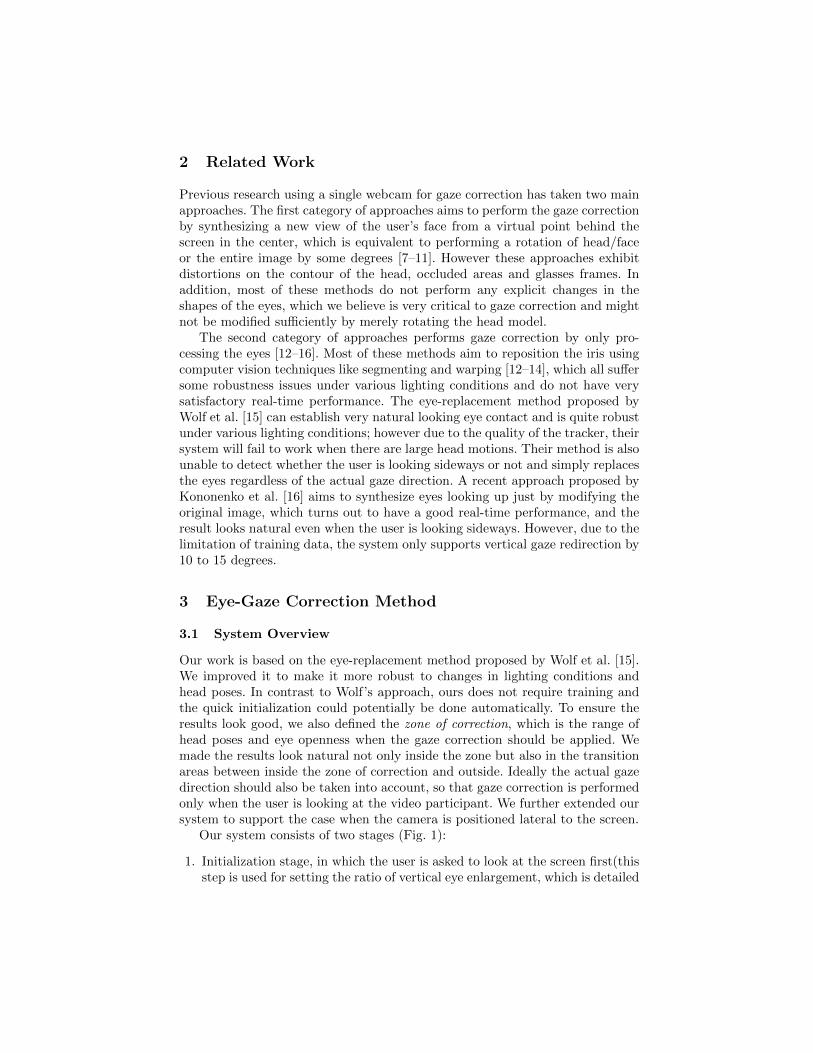
1. The pitch and yaw angles of head rotation are within some ranges when bothface tracking and eye replacement processes work well (Fig. 5). Accordingto our tests, they are ±10◦ for the pitch angle and ±19◦ for the yaw angle.
2. Correction should be applied only when the eyes are open. The degree ofopenness is measured by the ratio of the height of eye box to the width ofeye box. If it is larger than a threshold, a blink is detected and the correctionwill not be applied.
In order to provide a good user experience, we also define a transition zone(Fig. 5) in which alpha blending (cross-dissolving) is performed to make thetransition smooth. To achieve this, the alpha should be changed gradually from1.0 inside to 0.0 outside the transition zone. The algorithm that determines thevalue of alpha works as follows:
1. Check if the head pose direction is within the transition range of pitch angles.If it is, then alphaPitch = (maxOuterPitch - pitchAngle)/(maxOuterPitch- maxInnerPitch) (or (pitchAngle - minOuterPitch)/(minInnerPitch - mi-nOuterPitch) depending on the side). If it is outside both the correction andtransition zones, then alphaPitch = 0; Otherwise(inside the correction zone),alphaPitch = 1.
Fig. 5. Correction zone (indicated by the inner square pyramid) and transition zone(indicated by the space between the inner and outer square pyramids) of head pose.Each square pyramid, which is normal to the face plane, denotes the range of possi-ble head pose vectors. The boundary of the outer square pyramid is determined byfour angles: maxOuterPitch, minOuterPitch, maxOuterYaw, minOuterYaw. Similarly,the angles maxInnerPitch, minInnerPitch, maxInnerYaw, minInnerYaw determine theboundary of the inner square pyramid. These values are set as constants.
2. Compute alphaYaw for the yaw angles in a similar manner.3. The initial value of alpha is the minimum of alphaPitch and alphaYaw.4. The transition zone of eye openness is determined by minEllipseRatio and
maxEllipseRatio, which are minimum and maximum ratios of the height ofeye ellipse to the width of eye ellipse. Compute ratioEye as (maxEllipseRatio- curEyeRatio) / (maxEllipseRatio - minEllipseRatio) if the eye opennessis inside the transition zone, 1 if it is inside the correction zone and 0 ifotherwise.
5. The final alpha value is equal to the initial alpha value times ratioEye.
After we determine the value of alpha, the final image is computed as:
finalImage(x, y) = correctedImage(x, y) ·α+ originalImage(x, y)(1−α) (1)
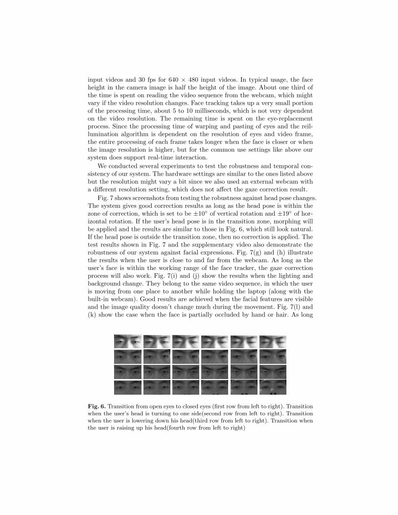
According to our experiments, when the transition happens during a blink,it does not make much difference whether we apply this blending or not sincethe corrected eye image is very similar to the original one in appearance whenthe eye is nearly closed (first row in Fig. 6). However when the transition occursduring a change of head pose, we can see some small artifacts around the eyecontours (last three rows in Fig. 6). This is mainly because of the small error ofeye point locations returned by the face tracker; given the 22+ fps of the videosequence, these small artifacts are not easily noticed.
4 Results
We tested our system on a laptop equipped with an Intel(R) Core(TM) i7-4710HQ CPU, 16GB RAM, and a NVIDIA GeForce GTX 860M (GPU acceler-ation not used). The frame rate of the built-in webcam is 22 fps for 800 × 600
input videos and 30 fps for 640 × 480 input videos. In typical usage, the faceheight in the camera image is half the height of the image. About one third ofthe time is spent on reading the video sequence from the webcam, which mightvary if the video resolution changes. Face tracking takes up a very small portionof the processing time, about 5 to 10 milliseconds, which is not very dependenton the video resolution. The remaining time is spent on the eye-replacementprocess. Since the processing time of warping and pasting of eyes and the reil-lumination algorithm is dependent on the resolution of eyes and video frame,the entire processing of each frame takes longer when the face is closer or whenthe image resolution is higher, but for the common use settings like above oursystem does support real-time interaction.
We conducted several experiments to test the robustness and temporal con-sistency of our system. The hardware settings are similar to the ones listed abovebut the resolution might vary a bit since we also used an external webcam witha different resolution setting, which does not affect the gaze correction result.
Fig. 7 shows screenshots from testing the robustness against head pose changes.The system gives good correction results as long as the head pose is within thezone of correction, which is set to be ±10◦ of vertical rotation and ±19◦ of hor-izontal rotation. If the user’s head pose is in the transition zone, morphing willbe applied and the results are similar to those in Fig. 6, which still look natural.If the head pose is outside the transition zone, then no correction is applied. Thetest results shown in Fig. 7 and the supplementary video also demonstrate therobustness of our system against facial expressions. Fig. 7(g) and (h) illustratethe results when the user is close to and far from the webcam. As long as theuser’s face is within the working range of the face tracker, the gaze correctionprocess will also work. Fig. 7(i) and (j) show the results when the lighting andbackground change. They belong to the same video sequence, in which the useris moving from one place to another while holding the laptop (along with thebuilt-in webcam). Good results are achieved when the facial features are visibleand the image quality doesn’t change much during the movement. Fig. 7(l) and(k) show the case when the face is partially occluded by hand or hair. As long
Fig. 6. Transition from open eyes to closed eyes (first row from left to right). Transitionwhen the user’s head is turning to one side(second row from left to right). Transitionwhen the user is lowering down his head(third row from left to right). Transition whenthe user is raising up his head(fourth row from left to right)

(a) 40◦ roll (b) 15◦ yaw (c) 10◦ pitch (d) -10◦ pitch (e) (f)
(g) (h) (i) (j) (k) (l)
Fig. 7. Good results. Top rows are original images and bottom rows are corrected ones.Please refer to our supplementary video for more results.
as the facial features like eyes and mouth are visible, the tracker will work andso will our gaze correction system. Our system also supports the cases when thecamera is positioned to the side of the screen (Fig 7(e)) or below the screen (Fig7(f)). According to our test results, our system works for almost all the camerapositions as long as the head pose in the image is within the correction zone,which means that the disparity angle between the locations of the camera andthe videoconferencing window should not be larger than 19 degrees horizontallyand 10 degrees vertically.
The supplementary video shows how our system performs in real time. Over-all the temporal consistency is good, i.e., the corrected eyes do not flicker muchfrom frame to frame. It still flickers a little bit from time to time due to thenoise of the image. We find that if a noise reduction algorithm is applied to eachframe beforehand the results become much more stable.
The results shown in Fig. 8 demonstrate some of the major limitations of oursystem. When the user is looking extremely sideways (Fig. 8(a)), the large areaof eye white may whiten the reilluminated eye image due to the limitation of ourreillumination method. When the user’s eyes are widely opened (Fig. 8(b)), theenlarged replacement eyes may differ from the actual eyes quite a lot, becauseof the difference between the captured direct looking eyes and the actual eyes.Moreover, if there are strong reflection of light on the glasses, the tracked eye

(a) (b) (c) (d)
Fig. 8. Unsatisfactory results. Top rows are original images and bottom rows are cor-rected ones. Please refer to our supplementary video for more results.
points may be very inaccurate and unstable, and therefore the final correctionresult will also look very bad (Fig. 8(c)).
One drawback of our gaze correction approach is that by simply replacingthe original eyes with the direct looking eyes, it ignores the actual gaze direction,i.e., the gaze direction in the corrected image does not change with the actualgaze direction (Fig. 8(d)). It would be preferable to perform gaze correctiononly when the user is looking directly at the screen, or design a gaze correctionapproach that takes into account the actual gaze correction.
5 Conclusion
In this paper we presented our gaze correction system based on eye-replacement,similar to Wolf et al. [15]. Compared to their approach, ours does not requiretraining, and we explicitly define the correction zone and handle the gaze in thetransition zone. Our system also supports more camera positions around thedisplay. According to our test results, the system has good robustness againstdifferent common lighting conditions and head poses. Our system is also shown tohave a good run-time speed and provide visually convincing and natural results.
Acknowledgements. This work was supported in part by Citrix Online andby NSF Grants IIS-1423676 and IIS-1219261.
References
1. Jones, A., Lang, M., Fyffe, G., Yu, X., Busch, J., McDowall, I., Bolas, M., Debevec,P.: Achieving eye contact in a one-to-many 3d video teleconferencing system. In:ACM Transactions on Graphics (TOG). Volume 28., ACM (2009) 64
2. Okada, K.I., Maeda, F., Ichikawaa, Y., Matsushita, Y.: Multiparty videoconfer-encing at virtual social distance: Majic design. In: Proceedings of the 1994 ACMconference on Computer supported cooperative work, ACM (1994) 385–393
3. Kuster, C., Popa, T., Bazin, J.C., Gotsman, C., Gross, M.: Gaze correction forhome video conferencing. ACM Transactions on Graphics (TOG) 31 (2012) 174
4. Zhu, J., Yang, R., Xiang, X.: Eye contact in video conference via fusion of time-of-flight depth sensor and stereo. 3D Research 2 (2011) 1–10
5. Criminisi, A., Shotton, J., Blake, A., Torr, P.H.: Gaze manipulation for one-to-oneteleconferencing. In: Computer Vision, 2003. Proceedings. Ninth IEEE Interna-tional Conference on, IEEE (2003) 191–198
6. Yang, R., Zhang, Z.: Eye gaze correction with stereovision for video-teleconferencing. In: Computer VisionECCV 2002. Springer (2002) 479–494
7. Cham, T.J., Krishnamoorthy, S., Jones, M.: Analogous view transfer for gazecorrection in video sequences. In: Control, Automation, Robotics and Vision, 2002.ICARCV 2002. 7th International Conference on. Volume 3., IEEE (2002) 1415–1420
8. Yip, B., Jin, J.S.: An effective eye gaze correction operation for video conferenceusing antirotation formulas. In: Information, Communications and Signal Process-ing, 2003 and Fourth Pacific Rim Conference on Multimedia. Proceedings of the2003 Joint Conference of the Fourth International Conference on. Volume 2., IEEE(2003) 699–703
9. Gemmell, J., Toyama, K., Zitnick, C.L., Kang, T., Seitz, S.: Gaze awareness forvideo-conferencing: A software approach. IEEE Multimedia 7 (2000) 26–35
10. Gemmell, J., Zhu, D.: Implementing gaze-corrected videoconferencing. In: Com-munications, Internet, and Information Technology. (2002) 382–387
11. Giger, D., Bazin, J.C., Kuster, C., Popa, T., Gross, M.: Gaze correction witha single webcam. In: Multimedia and Expo (ICME), 2014 IEEE InternationalConference on, IEEE (2014) 1–6
12. Hundt, E., Riegel, T., Schwartzel, H., Ziegler, M.: Correction of the gaze directionfor a videophone (1996) US Patent 5,499,303.
13. Jerald, J., Daily, M.: Eye gaze correction for videoconferencing. In: Proceedings ofthe 2002 symposium on Eye tracking research & applications, ACM (2002) 77–81
14. Weiner, D., Kiryati, N.: Virtual gaze redirection in face images. In: Image Analysisand Processing, 2003. Proceedings. 12th International Conference on, IEEE (2003)76–81
15. Wolf, L., Freund, Z., Avidan, S.: An eye for an eye: A single camera gaze-replacement method. In: Computer Vision and Pattern Recognition (CVPR), 2010IEEE Conference on, IEEE (2010) 817–824
16. Kononenko, D., Lempitsky, V.: Learning to look up: Realtime monocular gazecorrection using machine learning. In: Computer Vision and Pattern Recognition(CVPR), IEEE (2015)
17. Smith, B.A., Yin, Q., Feiner, S.K., Nayar, S.K.: Gaze locking: Passive eye contactdetection for human-object interaction. In: Proceedings of the 26th annual ACMsymposium on User interface software and technology, ACM (2013) 271–280
18. Xiong, X., De la Torre, F.: Supervised descent method and its applications to facealignment. In: Computer Vision and Pattern Recognition (CVPR), 2013 IEEEConference on, IEEE (2013) 532–539
19. Basri, R., Jacobs, D.W.: Lambertian reflectance and linear subspaces. PatternAnalysis and Machine Intelligence, IEEE Transactions on 25 (2003) 218–233
20. Bitouk, D., Kumar, N., Dhillon, S., Belhumeur, P., Nayar, S.K.: Face swapping:automatically replacing faces in photographs. In: ACM Transactions on Graphics(TOG). Volume 27., ACM (2008) 39
21. Burt, P.J., Adelson, E.H.: A multiresolution spline with application to imagemosaics. ACM Transactions on Graphics (TOG) 2 (1983) 217–236