extreme pneumatic ball valve instruction manual · specified in this manual are essential for...
TRANSCRIPT

In order to get the most from your actuated valve, it is advisable to carefully read the instructions below.
These symbols indicate potential danger should you not follow the advice set out here.
DANGER. Risk of electrocution. Failure to follow the advice set out here may result in electrocution.DANGER. Failure to follow the advice set out here may result in personal harm or damage to the apparatus.WARNING. Failure to follow the advice set out here may result in damage to the automatic valve or apparatus.
GENERAL SAFETY ADVICEThe valves described in this manual are especially designed to ensure a correct flow circulation in all working phases.Apparatus should be installed in accordance with the specific instructions for each installation. All existing safety legislation should be respected at all times in order to avoid accidents.Any modification to the pneumatic actuator requires the prior authorisation of the manufacturer. Spare parts and accessories authorised by the manufacturer are a guarantee of greater safety. The manufacturer of this actuated valve is exempt from all responsibility for damage arising from unauthorised spare parts and accessories.During operation, the electrical and pneumatic parts of this apparatus will have electrical current running through them. All work on the automatic valve and other related equipment should only be carried out having first disconnected the start up mechanism.The user should ensure that all assembly and maintenance work is carried out by suitably authorised, qualified personnel, and that these have previously read the installation and service instructions set out in this manual.Safe usage of this actuated valve can only be guaranteed by closely following the installation and service instructions laid out here.Voltage and air pressure limits should not be exceeded under any circumstances.In case of malfunction or breakdown, contact the nearest factory representative or technical assistance service department. Avoid shocks during transport, since they may damage the body and mechanism of the valve. Store the valve in the original packaging, protected against humidity and direct sunlight.
PNEUMATIC BALL VALVE WARNINGS
The maximum service life of the valve is specified in EN ISO 16135:2007. It is verified on the production plant by aging tests specified in the standard.Correct installation and handling of the valve, as well as adherence to the maximum pressure and temperature conditions specified in this manual are essential for preserving the service life of the valve.The driven liquid must be compatible with the valve materials. Consult chemical resistance charts published by Cepex or consult the technical department.Using tools for opening or closing the manual valve control is not recommended. Before carrying out any maintenance operations on the pipe or valve, ensure that the system is depressurised by releasing the pressure and emptying the pipes, following the specific safety regulations of each product.Before installation, check that the valve is undamaged and that it contains all the parts required for installation.After long periods of inactivity, check the grease on the o-rings and follow the maintenance instructions set out in this manual. The grease must be compatible with the valve materials.It is important to avoid rapid closure of valves to eliminate the possibility of water hammer causing damage to the pipeline.When using the valve as the final element of a installation, take into account the risks of the liquid and control the pressure and temperature, according to the standards of safety of each product.
Make all connections following the instruction referring to electrical supply as set out in this manual. Ensure that all cable leading top the electrovalve are correctly connected.Should you need to open the box at the end of the run, on closing again, check that it is correctly positioned to avoid any water contact. Also check that connectors are correctly situated.At all times, avoid contact, albeit accidental, with the actuated valve’s moving parts during operation and/or before it has come to a complete stop.Before beginning any electrical or pneumatic maintenance, ensure that the start-up mechanisms are blocked. It is advisable to follow the following steps before any alteration to the actuated valve:1.- Disconnect the electrovalve from the mains supply.2.- Block the pneumatic system’s start-up mechanisms.3.- Make certain that their is no voltage running through the circuits, including the auxiliary circuits and supplementary services.All the above should be taken as indicative and not directly tied to safety procedure as specific safety norms may be in place in some cases.IMPORTANT: As a result of the complexity of the subject, the installation, usage and maintenance instructions to be found in this manual are not designed to cover all imaginable service and maintenance scenarios. Should you require further instructions or encounter specific problems, please do not hesitate to contact the distributor or valve manufacturer.
EXTREME BALL VALVEPneumatic actuator
INSTALLATION AND MAINTENANCE MANUAL
1. DEFINITIONBall valve for isolating the flow in liquid handling systems. Design based on the EN ISO 16135:2007 Standard in accordance with the 97/23/EC Directive.The valve is available with PVC-U, CPVC, PP, PVDF and ABS bodys and EPDM and FPM sealing gaskets. The choice of material for the body and gaskets depends on the type of liquid to be carried and on the working temperature of the liquid, in accordance with the chemical resistance tables available on our website and the pressure/temperature chart in this Manual.The pneumatic actuator controls the positions of the valve (closed / opened).
2. COMPONENTS
N DESCRIPTION MATERIAL Q
1 EXTREME Ball Valve PVC-U, PP, CPVC, PVDF, ABS 1
2 Coupling bush Phosphochromate Aluminium 1
3 Mounting clamp PVC-U 1
4 Pneumatic actuator Anodised Aluminium / PA 1
5 Limit switch box (OPTIONAL: different models available)
1
6 Screw DIN-912 Stainless steel AISI-304 2
7 Screw DIN-912 Stainless steel AISI-304 4
8 Solenoid valve (OPTIONAL) 1
9 Relief regulator (OPTIONAL) 2
10 Adjusting Tool ABS 1
2.1 GENERAL ASSEMBLY
3. PNEUMATIC ACTUATED BALL VALVE TECHNICAL SPECIFICATIONSThe working pressure of the valve reduces with increasing liquid temperature, as shown in the accompanying chart.Air supply: Filtered air PNEUROP/ISO class 4.Air pressure: 6 bar ± 15%. In case of lower presure, ask to the technical department to check the torque of the actuator.Temperature range for the actuators:
Rotork aluminium actuator: -50ºC to 70 ºC.Prisma Plastic actuator: -32ºC to 90ºC.
All the actuators include NAMUR VDI/VDE 3845 interface for the electrovalve and the limit switch box.Rotork actuators can be ajusted 0-90º ± 5º, except DN15 and DN20 double acting.Prisma actuators are ATEX certified (ATEX EXII2Gc IP67 T6).To get more technical information about the actuators, please refer to the instruction manuals attached to the valve documentation.
Pressure / Temperature Chart. (G 3.1)
Pressure loss table (T3.3)
Valve operating torqueOperating torque values at rated pressure (PN) and 20 °C in as new direct from the factory condition. Installation and operating conditions (pressure and temperature) will affect these values. The actuator that is required for an automatic operation must be calculated according to some safety factors that were determined in life tests carried out in the factory.
DN15 DN20 DN25 DN32 DN40 DN50 DN65 DN80
N·m 1 2 3,5 3,5 5 15 25 45
lbf·inch 8,9 17,7 31 31 44,3 132,8 221,3 398,3
(T3.2)Operating torque table (N·m)
N DESCRIPTION MATERIAL Q
1 Body PVC-U, PPH, CPVC, PVDF, ABS 1
2 Shaft PVC-U, PPH, CPVC, PVDF, ABS 1
3 Ball PVC-U, PPH, CPVC, PVDF, ABS 1
4 Seal carrier PVC-U, PPH, CPVC, PVDF, ABS 1
5 Nut PVC-U, PPH, CPVC, PVDF, ABS 2
6 End connector PVC-U, PPH, CPVC, PVDF, ABS*Threaded versions with stainless steel ring
2
7 Ball Seat PTFE 2
8 O-ring EPDM / FPM 2
9 O-ring EPDM / FPM 2
10 O-ring EPDM / FPM 1
11 Dampener seal EPDM / FPM 2
12 Insert Stainless steel 4
2.2 EXTREME BALL VALVE BARE SHAFT
4. DIMENSIONS T 4.1(mm)DN D / G A ± 2
PVC-U, CPVC, ABSA’ ± 2
PP, PVDFB C E J K
10 16 - 3/8” 102 101 15,5 26 63 16 M4
15 20 - 1/2” 102 101 17 26 63 16 M4
20 25 - 3/4” 120 118 20 31,5 62 20 M5
25 32 - 1” 139 136 23 36 76 24 M5
32 40 - 1 1/4” 156 151 27,5 45 73 28 M5
40 50 - 1 1/2” 170 165 32 51 91 30 M8
50 63 - 2” 197 190 39 61 93 37,5 M8
65 75 - 2 1/2” 238 - 45 75 122 38 M8
80 90 - 3” 278 - 53 88,5 132 53 M8
Valve design Valve connections Actuator coupling
EN ISO 16135:2007 Threads: ISO 7-1, ISO 228-1Flanges: EN 558-1, EN 1092-1PVC-U, CPVC, ABS: ISO 15493PPH, PE-100: ISO 15494PVDF: ISO 10931
EN/ISO 5211
See the actuator and limit switch manuals to check the dimensions F, H and I.Check the technical catalog for the rest of dimensions for flange connections, PE-100 and the rest of end connectors.
DN ISO FLANGE SQUARE OPTIONS (mm)
15 F03-F04-F05 9/11/14
20 F03-F04-F05 9/11/14
25 F05 11/14
32 F05 11/14
40 F05-F07 11/14/17
50 F05-F07 11/14/17
65 F07 17
80 F07 17 / 22
PVC-U (PTFE-EPDM/FPM)CPVC (PTFE-EPDM/FPM)PPH (PTFE-EPDM/FPM)PVDF (PTFE-EPDM/FPM)ABS (PTFE-EPDM/FPM)
ENGLISH
Pres
sure
loss
/ P
erte
de
char
ge /
Pér
dida
de
carg
a /
Perd
ita d
i car
ico
/ D
ruck
verlu
st /
Per
das
de c
arga
Flow / Débit / Caudal / Portata / Durchfluss / Caudal
Fig. 2
Pressure loss chart (G 3.3)
PVC-U
0 10 20 30 40 50 60 70 80 90 100
32 50 68 86 104 122 140 158 176 194 212
PVC-C
PP-H
-30 -20 -10 0 10 20 30 40 50 60 70 80 90 100 110 120
-22 -4 14 32 50 68 86 104 122 140 158 176 194 212 230 248
PVDF
ABS
G 3.2
Fig. 1
Fig. 3
Fig. 5
Fig. 4K
DN D Kv (l/min) Cv (GPM)
10 16 75 5,3
15 20 190 13,3
20 25 380 26,6
25 32 690 48,3
32 40 980 68,6
40 50 1600 112
50 63 3000 210,1
65 75 5500 385,2
80 90 6800 476,2
Important: This instruction manual contains essential information regarding the safety measures to adopt when installing and starting up the equipment. It is therefore essential that the user reads these instructions before installing and starting to use the apparatus.
EXTREME PNEUMATIC BALL VALVE ENGLISH EXTREME PNEUMATIC BALL VALVE
psi bar
psi bar
ºCºF
ºCºF
PVC-U
0 10 20 30 40 50 60 70 80 90 100
32 50 68 86 104 122 140 158 176 194 212
PVC-C
DN65 - DN80 (PVC-U, CPVC)
ºCºF
psi bar
Actuator coupling dimensions (T4.2)
8
9
7
6
5
1
2
3
4
10
5. INSTALLATION AND COMMISSIONINGBefore commencing the installation process, check that you have all the parts needed for the valve assembly, and that the materials, connection type and nominal pressure are suitable for the installation. For solvent or welded connections, ensure also that the parts to be connected are of the same material and that you are using the correct solvent or welding tools.To install the valve, follow best installation practice recommendations provided on the Cepex website, paying particular attention to thermal expansion and pipe alignment. When filling the pipes with liquid, check that all the air is purged from the system and that the initial pressure does not exceed the nominal pressure of the valve, or of the system element with the lowest nominal pressure rating.Install the valve pointing in the direction of flow marked on the body of the valve (downstream).Install the valve once the sockets are solvent-bonded and dry, to avoid problems with the adhesive (entry of the latter into the valve).
6. VALVE FUNCTION6.1 SPRING RETURN NORMALLY CLOSED VALVE (Fig. 9)The valve is closed without air supply. When the actuator is supplied with pressurized air, the valve opens. If the supply of the pressurized air is closed and the escape of the air is permitted, the valve will be closed because of the internal springs of the actuator.3/2 solenoid valve or 5/2 solenoid valve is required to do the action. In case of the installation of a monostable normally closed solenoid valve, the electrical signal should be kept during the time that the valve needs to be opened.In case of spring return actuator, Cepex will serve normally closed valve as standard.
6.2 SPRING RETURN NORMALLY OPEN VALVE (Fig. 10)The valve is opened without air supply. When the actuator is supplied with pressurized air, the valve closes. If the supply of the pressurized air is closed and the escape of the air is permitted, the valve will be opened because of the internal springs of the actuator.3/2 solenoid valve or 5/2 solenoid valve is required to do the action. In case of the installation of a monostable normally closed solenoid valve, the electrical signal should be kept during the time that the valve needs to be closed.
6.3 DOUBLE ACTING VALVE (Fig.11)The valve has no defined fail safe position. The valve is opened and closed by applying control pressure to the corresponding control connections.5/2 solenoid valve is required to do the action. In case of the installation of a monostable normally closed solenoid valve, the electrical signal should be kept during the time that the valve needs to be opened (according to the drawing).
2
31
10
OPEN VALVE
2
31
10
CLOSED VALVE
2
31
10
CLOSED VALVE
2
31
10
OPEN VALVEFig. 9
Fig. 10
Fig. 11
6.4 LIMIT SWITCH BOXTo confirm electrically the position of the valve, a limit switch box can be mounted to the actuator according to NAMUR specification. Protection IP67. Temperature range: -20ºC to 80ºC.There are available limit switch boxes made in plastic and aluminium.Electromechanical switches SPDT as standard.See the specific manual and the electrical schema inside the box.
14
4 2
315
14
4 2
315
CLOSED VALVE OPEN VALVE
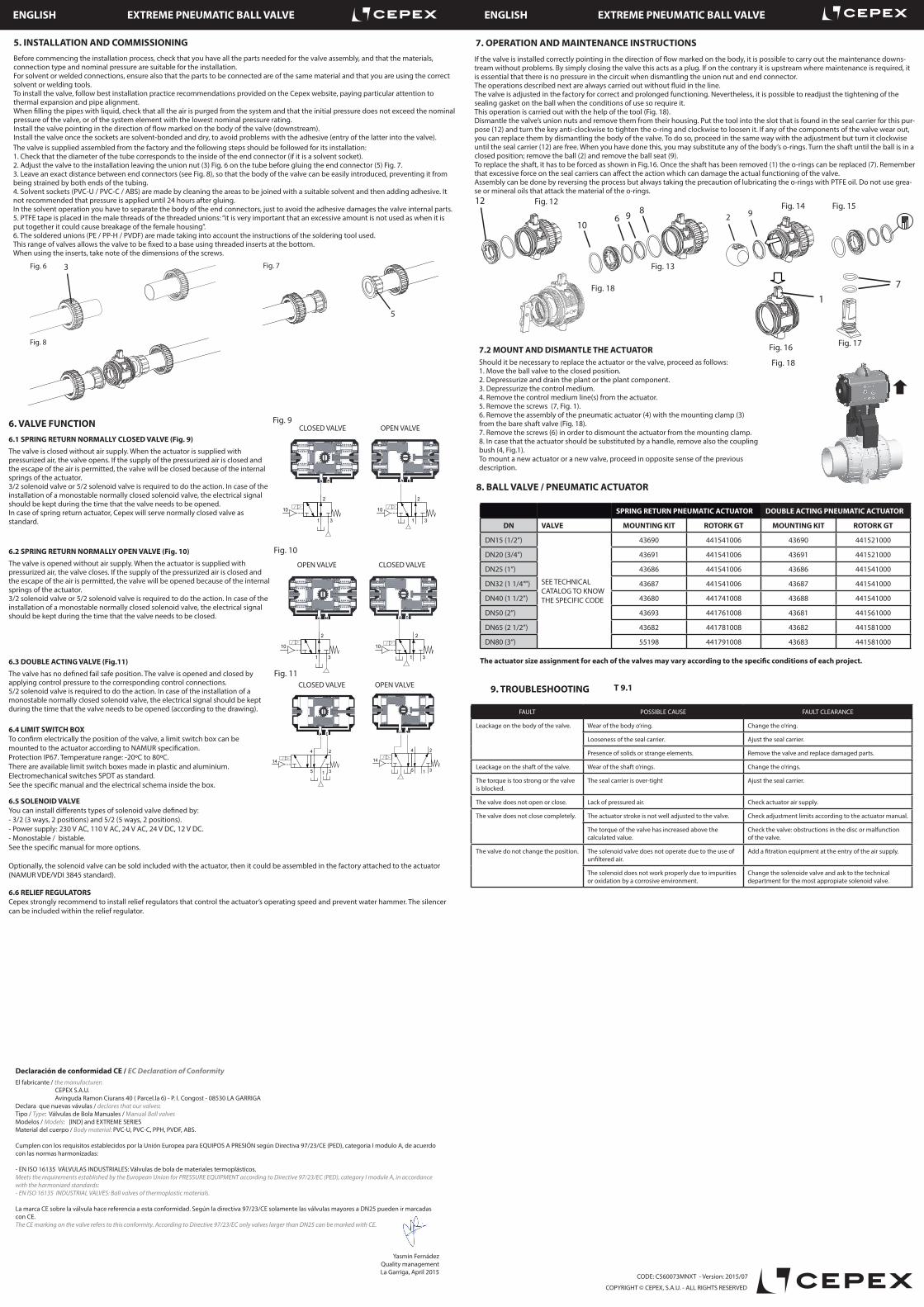
7. OPERATION AND MAINTENANCE INSTRUCTIONS
7.2 MOUNT AND DISMANTLE THE ACTUATORShould it be necessary to replace the actuator or the valve, proceed as follows:1. Move the ball valve to the closed position.2. Depressurize and drain the plant or the plant component.3. Depressurize the control medium.4. Remove the control medium line(s) from the actuator.5. Remove the screws (7, Fig. 1).6. Remove the assembly of the pneumatic actuator (4) with the mounting clamp (3) from the bare shaft valve (Fig. 18).7. Remove the screws (6) in order to dismount the actuator from the mounting clamp.8. In case that the actuator should be substituted by a handle, remove also the coupling bush (4, Fig.1).To mount a new actuator or a new valve, proceed in opposite sense of the previous description.
8. BALL VALVE / PNEUMATIC ACTUATOR
SPRING RETURN PNEUMATIC ACTUATOR DOUBLE ACTING PNEUMATIC ACTUATOR
DN VALVE MOUNTING KIT ROTORK GT MOUNTING KIT ROTORK GT
DN15 (1/2”)
SEE TECHNICAL CATALOG TO KNOW THE SPECIFIC CODE
43690 441541006 43690 441521000
DN20 (3/4”) 43691 441541006 43691 441521000
DN25 (1”) 43686 441541006 43686 441541000
DN32 (1 1/4””) 43687 441541006 43687 441541000
DN40 (1 1/2”) 43680 441741008 43688 441541000
DN50 (2”) 43693 441761008 43681 441561000
DN65 (2 1/2”) 43682 441781008 43682 441581000
DN80 (3”) 55198 441791008 43683 441581000
9. TROUBLESHOOTING T 9.1
FAULT POSSIBLE CAUSE FAULT CLEARANCE
Leackage on the body of the valve. Wear of the body o’ring. Change the o’ring.
Looseness of the seal carrier. Ajust the seal carrier.
Presence of solids or strange elements. Remove the valve and replace damaged parts.
Leackage on the shaft of the valve. Wear of the shaft o’rings. Change the o’rings.
The torque is too strong or the valve is blocked.
The seal carrier is over-tight Ajust the seal carrier.
The valve does not open or close. Lack of pressured air. Check actuator air supply.
The valve does not close completely. The actuator stroke is not well adjusted to the valve. Check adjustment limits according to the actuator manual.
The torque of the valve has increased above the calculated value.
Check the valve: obstructions in the disc or malfunction of the valve.
The valve do not change the position. The solenoid valve does not operate due to the use of unfiltered air.
Add a fitration equipment at the entry of the air supply.
The solenoid does not work properly due to impurities or oxidation by a corrosive environment.
Change the solenoide valve and ask to the technical department for the most appropiate solenoid valve.
6.5 SOLENOID VALVEYou can install differents types of solenoid valve defined by:- 3/2 (3 ways, 2 positions) and 5/2 (5 ways, 2 positions).- Power supply: 230 V AC, 110 V AC, 24 V AC, 24 V DC, 12 V DC.- Monostable / bistable.See the specific manual for more options.
Optionally, the solenoid valve can be sold included with the actuator, then it could be assembled in the factory attached to the actuator (NAMUR VDE/VDI 3845 standard).
6.6 RELIEF REGULATORSCepex strongly recommend to install relief regulators that control the actuator’s operating speed and prevent water hammer. The silencer can be included within the relief regulator.
COPYRIGHT © CEPEX, S.A.U. - ALL RIGHTS RESERVED
The valve is supplied assembled from the factory and the following steps should be followed for its installation:1. Check that the diameter of the tube corresponds to the inside of the end connector (if it is a solvent socket).2. Adjust the valve to the installation leaving the union nut (3) Fig. 6 on the tube before gluing the end connector (5) Fig. 7.3. Leave an exact distance between end connectors (see Fig. 8), so that the body of the valve can be easily introduced, preventing it from being strained by both ends of the tubing.4. Solvent sockets (PVC-U / PVC-C / ABS) are made by cleaning the areas to be joined with a suitable solvent and then adding adhesive. It not recommended that pressure is applied until 24 hours after gluing.In the solvent operation you have to separate the body of the end connectors, just to avoid the adhesive damages the valve internal parts.5. PTFE tape is placed in the male threads of the threaded unions: “it is very important that an excessive amount is not used as when it is put together it could cause breakage of the female housing”.6. The soldered unions (PE / PP-H / PVDF) are made taking into account the instructions of the soldering tool used.This range of valves allows the valve to be fixed to a base using threaded inserts at the bottom.When using the inserts, take note of the dimensions of the screws.
If the valve is installed correctly pointing in the direction of flow marked on the body, it is possible to carry out the maintenance downs-tream without problems. By simply closing the valve this acts as a plug. If on the contrary it is upstream where maintenance is required, it is essential that there is no pressure in the circuit when dismantling the union nut and end connector.The operations described next are always carried out without fluid in the line.The valve is adjusted in the factory for correct and prolonged functioning. Nevertheless, it is possible to readjust the tightening of the sealing gasket on the ball when the conditions of use so require it.This operation is carried out with the help of the tool (Fig. 18).Dismantle the valve’s union nuts and remove them from their housing. Put the tool into the slot that is found in the seal carrier for this pur-pose (12) and turn the key anti-clockwise to tighten the o-ring and clockwise to loosen it. If any of the components of the valve wear out, you can replace them by dismantling the body of the valve. To do so, proceed in the same way with the adjustment but turn it clockwise until the seal carrier (12) are free. When you have done this, you may substitute any of the body’s o-rings. Turn the shaft until the ball is in a closed position; remove the ball (2) and remove the ball seat (9).To replace the shaft, it has to be forced as shown in Fig.16. Once the shaft has been removed (1) the o-rings can be replaced (7). Remember that excessive force on the seal carriers can affect the action which can damage the actual functioning of the valve.Assembly can be done by reversing the process but always taking the precaution of lubricating the o-rings with PTFE oil. Do not use grea-se or mineral oils that attack the material of the o-rings.
3
5
Fig. 6 Fig. 7
Fig. 8
Fig. 12 Fig. 1412
106 9 8
2 9
Fig. 15
Fig. 13 1
7
Fig. 16 Fig. 17
Fig. 18
The actuator size assignment for each of the valves may vary according to the specific conditions of each project.
ENGLISH EXTREME PNEUMATIC BALL VALVE ENGLISH EXTREME PNEUMATIC BALL VALVE
CODE: C560073MNXT - Version: 2015/07
Declaración de conformidad CE / EC Declaration of ConformityEl fabricante / the manufacturer: CEPEX S.A.U. Avinguda Ramon Ciurans 40 ( Parcel.la 6) - P. I. Congost - 08530 LA GARRIGADeclara que nuevas vávulas / declares that our valves:Tipo / Type: Válvulas de Bola Manuales / Manual Ball valvesModelos / Models: [IND] and EXTREME SERIESMaterial del cuerpo / Body material: PVC-U, PVC-C, PPH, PVDF, ABS.
Cumplen con los requisitos establecidos por la Unión Europea para EQUIPOS A PRESIÓN según Directiva 97/23/CE (PED), categoria I modulo A, de acuerdo con las normas harmonizadas:
- EN ISO 16135 VÁLVULAS INDUSTRIALES: Válvulas de bola de materiales termoplásticos.Meets the requirements established by the European Union for PRESSURE EQUIPMENT according to Directive 97/23/EC (PED), category I module A, in accordance with the harmonized standards:- EN ISO 16135 INDUSTRIAL VALVES: Ball valves of thermoplastic materials.
La marca CE sobre la válvula hace referencia a esta conformidad. Según la directiva 97/23/CE solamente las válvulas mayores a DN25 pueden ir marcadas con CE.The CE marking on the valve refers to this conformity. According to Directive 97/23/EC only valves larger than DN25 can be marked with CE.
Yasmin Fernádez Quality management
La Garriga, April 2015
Fig. 18