extreme light infrastructure nuclear physics (eli np) an automatic ... s-band structures, rf...
TRANSCRIPT

November 16th , 2016 University of Applied Sciences, Brugg/Windisch, Switzerland
GOVERNMENT OF ROMANIA
Structural Instruments
2007-2013 EUROPEAN UNION
Sectoral Operational Programme
„Increase of Economic Competitiveness”
“Investments for Your Future”
Extreme Light Infrastructure – Nuclear Physics (ELI–NP)
Project co–financed by the European Regional Development Fund
PIOTR TRACZ [email protected]
FOR THE ELI-NP TEAM

March 19, 2014
Academic Institutions
INFN (Italy), Sapienza University (Italy), CNRS (France)
Industrial Partners
ACP Systems (France), ALSYOM (France),
COMEB (Italy), ScandiNova Systems (Sweden)
and several Sub-Contractors:
Alba (Spain), STFC (UK)
Amplitude Systems (France), Amplitude Technology (France), iTech
(Slovenia), Cosylab (Slovenia), Danfysik (Denmark), M&W Group
(Italy), Menlo Systems (Germany), RI (Germany),
Provider – EuroGammaS Association
Horia Hulubei National Institute of Physics and Nuclear Engineering (IFIN-HH)
~12 km
19/03/2014

Compton backscattering between a relativistic electron bunch and a high power laser pulse.
Low cross section (~ 10-25 cm2)
need of high density of electron and photon beams
0.2J 𝐸𝑒~ 300𝑀𝑒𝑉 𝐸𝛾 < 3.5 𝑀𝑒𝑉 (Low Energy Branch)
(2.4𝑒𝑉, 515𝑛𝑚 – green)
2 x 0.2J 𝐸𝑒~ 720 𝑀𝑒𝑉 𝐸𝛾 ≤ 19 𝑀𝑒𝑉 (High Energy Branch)
Angular dependence of the photon energy
angle (energy) –> to choose by collimator
Laser pulse (3.5ps) energy: Compton backscattering geometry
e- beam is moving at a relativistic speed
from left to right, colliding with a photon
beam emitting scattered radiation mainly
in the direction of motion of the e- beam.
Result:
generation of high brilliance 𝛾-ray beam with number of advantages
over the more conventional bremsstrahlung sources, which are based on
impinging the electron beam onto a solid target of high Z material:
¤ good and controllable monochromaticity,
¤ easy tunability,
¤ higher collimation
¤ full control of the gamma photon polarization.

Compton backscattering between a relativistic electron bunch and a high power laser pulse.
Low cross section (~ 10-25 cm2)
need of high density of electron and photon beams
0.2J 𝐸𝑒~ 300𝑀𝑒𝑉 𝐸𝛾 < 3.5 𝑀𝑒𝑉 (Low Energy Branch)
(2.4𝑒𝑉, 515𝑛𝑚 – green)
2 x 0.2J 𝐸𝑒~ 720 𝑀𝑒𝑉 𝐸𝛾 ≤ 19 𝑀𝑒𝑉 (High Energy Branch)
Angular dependence of the photon energy
angle (energy) –> to choose by collimator
Laser pulse (3.5ps) energy: Compton backscattering geometry
e- beam is moving at a relativistic speed
from left to right, colliding with a photon
beam emitting scattered radiation mainly
in the direction of motion of the e- beam.
Photon Energy up to 19.5 MeV
Spectral Density 104 ph/sec/eV
Bandwidth (rms) ≤ 0.5%
# photons / shot within FWHM bdw. 2.6 · 105 (max)
# photons / sec within FWHM bdw. 8.3 · 108 (max)
Source rms size 10 ÷ 30 µm
Source rms divergence 30 ÷ 200 µrad
Peak brilliance (Nph/sec mm2 mrad2 0.1%) 1020 ÷ 1023
Pulse length (rms) 0.7 ÷ 1.5 ps
Linear polarization > 99%
Repetition Rate 100 Hz
Source position transverse jitter < 5 µm
Energy jitter pulse-to-pulse < 0.2 %
# pulses per macro-pulse 32
Pulse-to-pulse separation 16 ns

Energy up to 720 MeV
Bunch charge 250 pC
Bunch length 1 ps
Norm. transverse emittance 0.4 mmmrad
Bunch energy spread 0.04 ÷ 0.1 %
Focal spot size ~ 15 µm
Number of bunches 32
Bunch-to-bunch distance 16 ns
Energy variation along macro-bunch
0.1%
Energy jitter shot to shot 0.1%
Time arrival jitter < 0.5 ps
Pointing jitter 1 µm
Bunch rep rate 100 Hz
The Gamma Beam System is based on warm RF linac operated at C-band
with S-band photo-injector.
Electron beam parameters at Interaction Points
We need:
a) high brightness (high charge, low emittance, low energy spread) and high
phase space density electron beam carrying 250pC per bunch in bunch
trains of 32 bunches per RF pulse, focused down to spot sizes of about
15µm.
b) laser beam of high intensity, very brilliant, high repetition rate.
Ti:sapphire laser for photocathode RF gun
Output: ~10ps pulse duration in UV range (266nm),
150µJ/pulse, sequence of trains made of 32 pulses
separated by 16ns @100Hz rep. rate.
Yb:YAG lasers for Interaction Points with 3.5 ps
pulse duration (FWHM) at 515 nm, 0.2J, 100Hz,
0.1% (rms) bandwidth, and pulse energy stability of 1%.

𝜸 beam Collimator & Diagnostics
Photo-cathode RF Gun
2x S-band TW structures
e- RF linac 4x C-band TW structures
Dipole magnet
Interaction Point Low Energy
e- beam dump
LOW ENERGY BRANCH HIGH ENERGY BRANCH
Photo-cathode Laser
Racks Room
Interaction Laser Low Energy
Control Room
Racks Room
Interaction Laser High Energy
end stations experiments
Low Energy Linac (𝑬𝒆 ≈ 𝟑𝟎𝟎𝑴𝒆𝑽 → 𝑬𝜸 ≈ 𝟑. 𝟓𝑴𝒆𝑽)

𝜸 beam Collimator & Diagnostics
e- RF linac 8 + 4 x C-band TW structure
Photo-cathode RF Gun
2x S-band TW structures
e- RF linac 4x C-band TW structures
Interaction Point Low Energy
e- beam dump
LOW ENERGY BRANCH HIGH ENERGY BRANCH
Photo-cathode Laser
Racks Room
Interaction Laser Low Energy
Control Room
Racks Room
Interaction Laser High Energy
High Energy Linac (𝑬𝒆 ≈ 𝟕𝟐𝟎𝑴𝒆𝑽 → 𝑬𝜸 ≈ 𝟏𝟖𝑴𝒆𝑽)
Interaction Point High Energy
e- beam dump
end stations experiments
Master Clock synchronization @ < 1ps
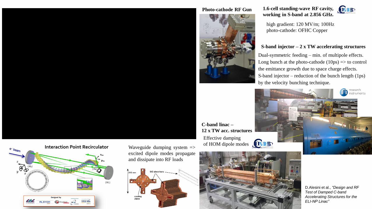
S-band injector – 2 x TW accelerating structures
Dual-symmetric feeding – min. of multipole effects.
Long bunch at the photo-cathode (10ps) => to control
the emittance growth due to space charge effects.
S-band injector – reduction of the bunch length (1ps)
by the velocity bunching technique.
C-band linac –
12 x TW acc. structures
Effective damping
of HOM dipole modes Interaction Point Recirculator
Photo-cathode RF Gun 1.6-cell standing-wave RF cavity,
working in S-band at 2.856 GHz.
high gradient: 120 MV/m; 100Hz
photo-cathode: OFHC Copper
D.Alesini et al., “Design and RF
Test of Damped C-band
Accelerating Structures for the
ELI-NP Linac”
Waveguide dumping system =>
excited dipole modes propagate
and dissipate into RF loads

Repetition Rate – 100 Hz
32 bunches separated by 16 ns
Laser Recirculator -> Single laser pulse is recirculated 32 times, synchronized with RF clock.
The laser beam is reflected and focused to the Interaction Point (IP) with the parabolic
mirrors (sharing the same focal point. ).
Mirror Pair System (MPS) - enables to shift the laser beam path in respect to parabolic
mirrors and to delay in order to synchronize the laser pulse over the electron bunches.
2 parabolic reflectors M1& M2
- M1 fixed
- M2 : 5 degrees of freedom
Laser Recirculator:
• Highly complex optical implementation
Laser pulse rep. rate – 100 Hz
→ laser recirculation


July-August 2016

Building Acceptance
June-September 2016
Vibration Measurements – Gerb Engineering GmbH
Laser tracker 3D scanning for check the real
dimensions and volumes of the rooms.
Location of all openings etc.
Electrical measurements – grounding parameters,
short-circuit current, grid voltage monitoring.
Tests of BMS, Ventilation System, Alarm system etc.

KLYSTRON MODULATORS
Electron Gun Injector Booster
Frequency [GHz] 2.856 2.856 5.712
Output Peak Power [MW]
45 60 50
Pulse length [µs] 5 1,5 0,5
Rep. Rate [Hz] 100 100 100
2856MHz; 60MW 5712MHz; 50MW
1st phase of machine delivery
2nd phase of machine delivery
3rd phase of machine delivery
To beam dump
Waveguide systems
March 19, 2014
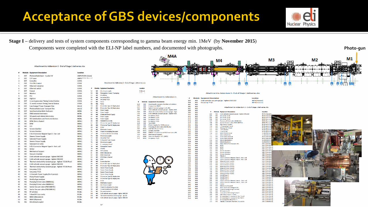
Stage I – delivery and tests of system components corresponding to gamma beam energy min. 1MeV (by November 2015)
Components were completed with the ELI-NP label numbers, and documented with photographs. Photo-gun

STFC, Daresbury, UK
Provided two modules M4 and M4A (mounted components and aligned with
laser tracker)
M4 – C-band accelerating structure, 3x quadrupole magnets and a dipole
magnet. M4A – beam dump.
Every module is completed with horizontal and vertical steerers for beam
position adjustment, beam position monitor systems (BPM) and OTR
screens for beam profile analysis, vacuum elements (gauges, ion pumps,
manual an automatic valves), power supplies.
(Stage II – modules M5 to M8 were in advanced stage of mounting.)
INFN, Frascati, Italy
Modules M1, M2, M3 (components mounted and aligned with laser tracker)
Every module is completed with horizontal and vertical steerers for beam
position adjustment, beam position monitor system (BPM) and screens for
beam profile analysis, vacuum elements, power supplies

Scandinova, Uppsala, Sweden
- Modulators and klystrons – modulators MSB1, MSB2,
MSB3, MCB1
Research Instruments, Bonn/Bergish Gladbach, Germany
- Power conditioning of S- and C-band accelerating structures, and photo-gun
- Photo-gun, S-band structures, RF waveguides, vacuum components, directional
couplers, RF windows.
- RI will install RF components in the ELI-NP building,
- Takes care of the implementation of the network of reference points for the
accelerator alignment in the ELI-NP building.
Menlo Systems, Munich, Germany
- Timing systems for synchronization at femtoseconds level
- Timing distribution needed to synchronize the electron beam and the laser
pulses at the interaction point with an accuracy better than 500fs.
- The system is based on Optical Master Oscillator and Stabilized Fiber
Links, ensuring the synchronization of the RF and laser systems.
Cosylab, Ljubljana, Slovenia
- Delivery of the software and hardware necessary to control the modules M1 to M4
Acceptance of GBS devices/components

ACP Systems, Amplitude Systems, France
Interaction laser IP1 – delivery of configuration able to provide
pulses of 100µJ at 100Hz repetition rate and 515nm wavelength.
Amplitude Technologies, Lisses, France
Photocathode laser: stretcher, 100Hz regenerative amplifier, 100Hz multi-
pass pre-amplifier, 2 x 100Hz multi-pass amplifiers, compressor, pump
lasers.
Tests of module were successful being able to produce the 32 pulses
separated at 16ns with an intensity fluctuations below 5%.
LAL CNRS, Orsay, France
Laser beam transport lines for photocathode laser and IP1.
Acceptance of GBS devices/components

Thank You for Your Attention
www.eli-np.ro
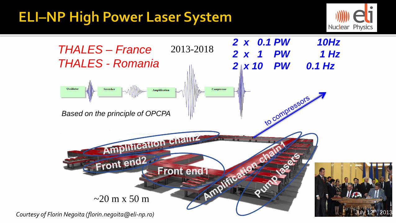
Based on the principle of OPCPA
2 x 0.1 PW 10Hz
2 x 1 PW 1 Hz
2 x 10 PW 0.1 Hz
THALES – France
THALES - Romania
2013-2018
~20 m x 50 m
Courtesy of Florin Negoita ([email protected]) July 12th, 2013
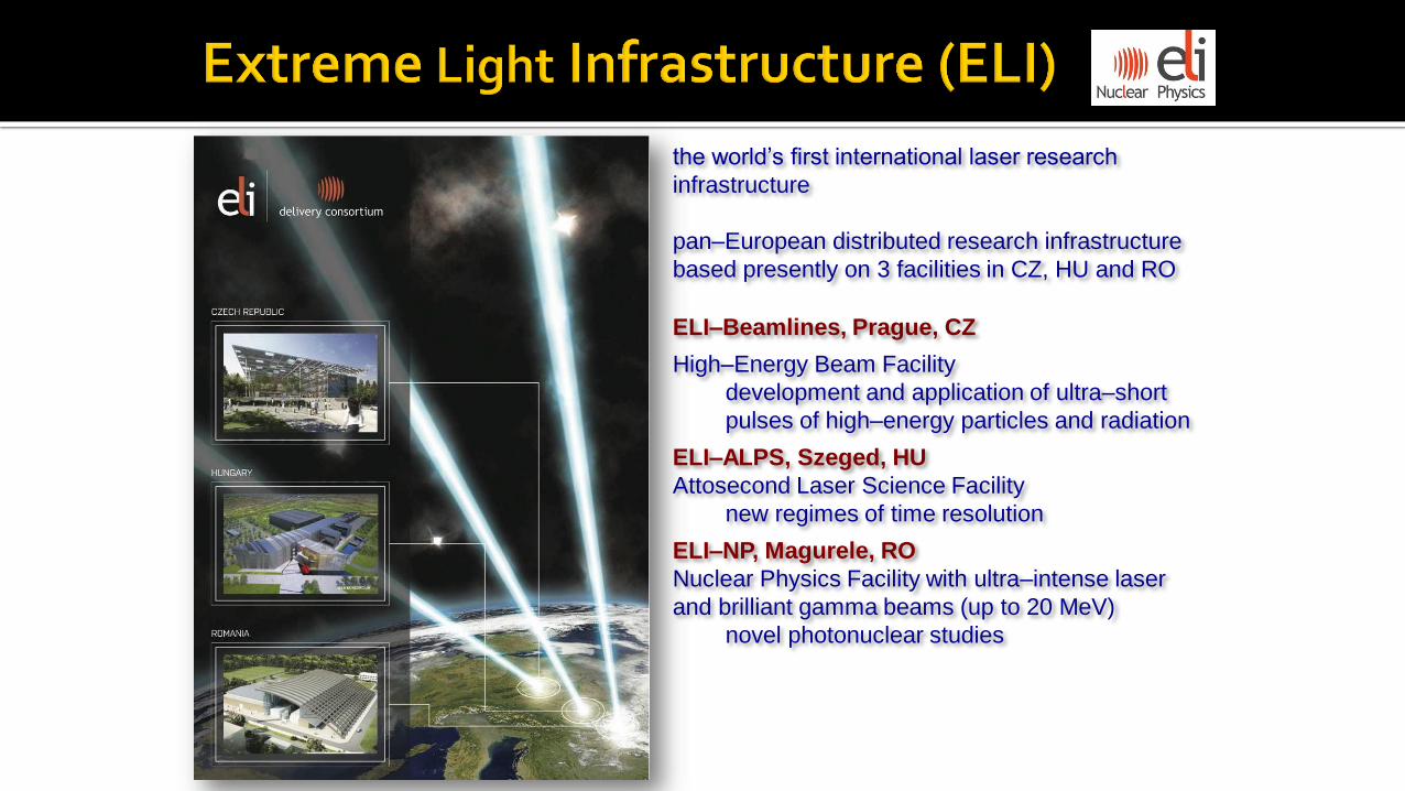
ELI–Beamlines, Prague, CZ
High–Energy Beam Facility
development and application of ultra–short
pulses of high–energy particles and radiation
ELI–ALPS, Szeged, HU
Attosecond Laser Science Facility
new regimes of time resolution
ELI–NP, Magurele, RO
Nuclear Physics Facility with ultra–intense laser
and brilliant gamma beams (up to 20 MeV)
novel photonuclear studies
the world’s first international laser research
infrastructure
pan–European distributed research infrastructure
based presently on 3 facilities in CZ, HU and RO

ELI Delivery Consortium
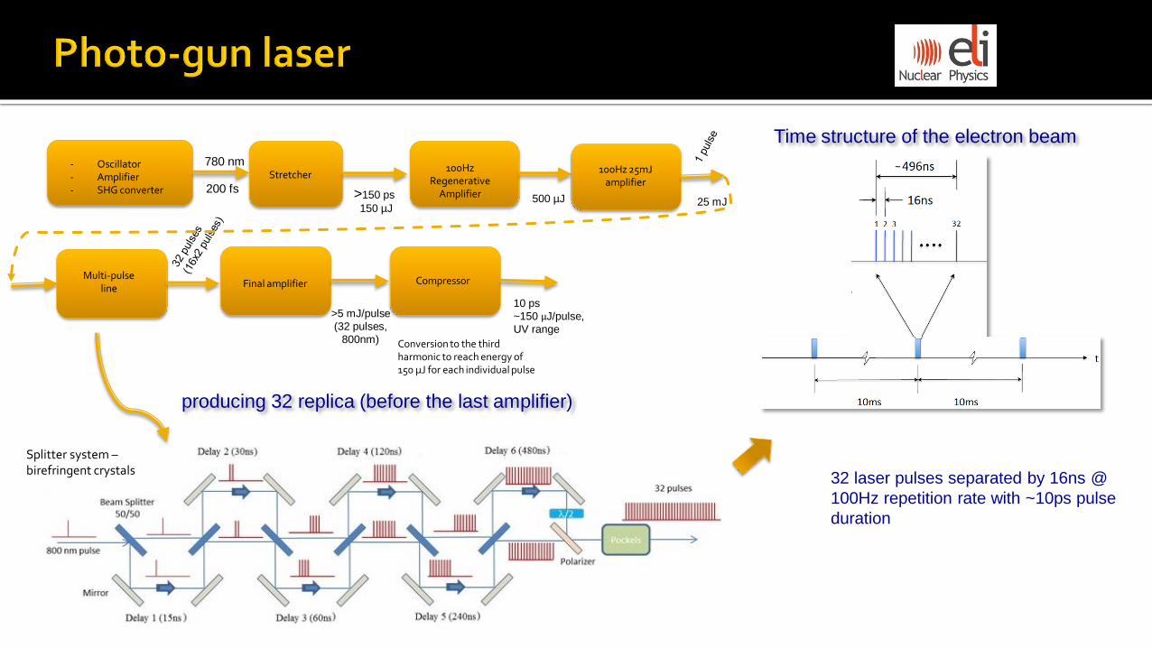
producing 32 replica (before the last amplifier)
500 µJ
- Oscillator - Amplifier - SHG converter
780 nm Stretcher
>150 ps
150 µJ
200 fs
100Hz Regenerative
Amplifier
100Hz 25mJ amplifier
25 mJ
Final amplifier
>5 mJ/pulse
(32 pulses,
800nm)
Compressor
10 ps
~150 µJ/pulse,
UV range
Multi-pulse line
Time structure of the electron beam
~
32 laser pulses separated by 16ns @
100Hz repetition rate with ~10ps pulse
duration
Conversion to the third harmonic to reach energy of 150 µJ for each individual pulse
Splitter system – birefringent crystals
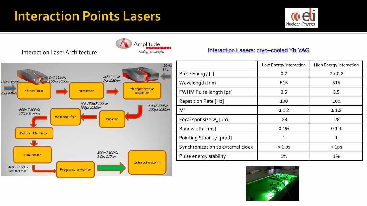
Interaction Laser Architecture Interaction Lasers: cryo–cooled Yb:YAG
Low Energy Interaction High Energy Interaction
Pulse Energy [J] 0.2 2 x 0.2
Wavelength [nm] 515 515
FWHM Pulse length [ps] 3.5 3.5
Repetition Rate [Hz] 100 100
M2 ≤ 1.2 ≤ 1.2
Focal spot size w0 [µm] 28 28
Bandwidth [rms] 0.1% 0.1%
Pointing Stability [µrad] 1 1
Synchronization to external clock < 1 ps < 1ps
Pulse energy stability 1% 1%
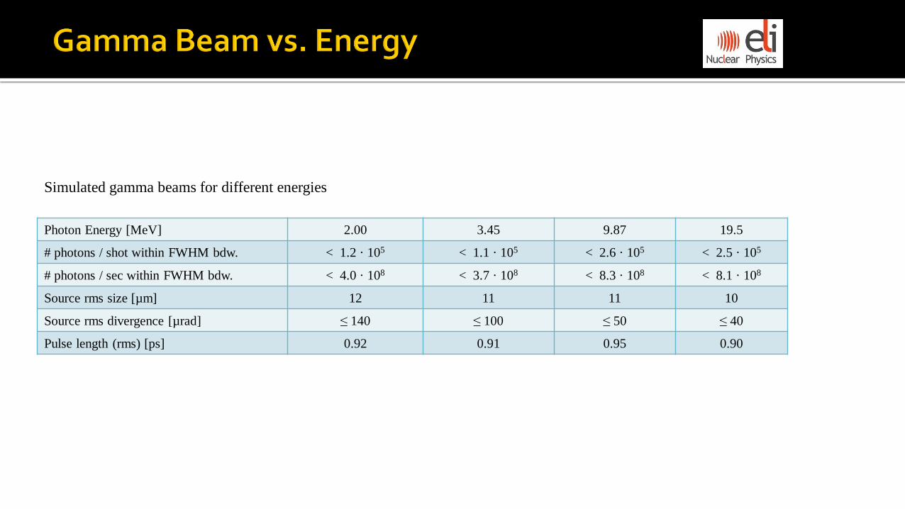
Photon Energy [MeV] 2.00 3.45 9.87 19.5
# photons / shot within FWHM bdw. < 1.2 · 105 < 1.1 · 105 < 2.6 · 105 < 2.5 · 105
# photons / sec within FWHM bdw. < 4.0 · 108 < 3.7 · 108 < 8.3 · 108 < 8.1 · 108
Source rms size [µm] 12 11 11 10
Source rms divergence [µrad] ≤ 140 ≤ 100 ≤ 50 ≤ 40
Pulse length (rms) [ps] 0.92 0.91 0.95 0.90
Simulated gamma beams for different energies

Multi-bunch mode -> wakefields (both longitudinal and transverse components 𝑭 ≡ 𝑭|| + 𝑭⊥) -> affect
the longitudinal (changes energy) and transverse (deflects trajectory) beam dynamics. Longitudinal components -> beam loading effects -> increase of energy spread and decrease of accelerating field gradient in the structure. Transverse components (BBU) -> drive instability along the train generating the HOM dipole modes. (off-axis beam trajectories)
High quality gamma beam -> requires high quality electron beam
Courtesy of D. Alesini
compact system High gradient C-band linac combined with S-band Injector
• Low emittance, low energy spread, and high beam charge • To increase the gamma flux we need to increase the number of collision per second.
100 Hz repetition rate
Multi bunch
• Dumping of HOM dipole modes in RF structures to avoid BBU (beam break-up) instabilities • Compensation of beam loading effects • Accurate thermal design (high average dissipate power)
-> Waveguide dumping system with silicon-carbide (SiC) RF loads -> amplitude modulation of the input RF power along the e- beam train to reduce the energy spread -> each structure has 14 water cooling channels for temperature stabilization; water flow of 66 litre /min

Laser-driven photocathode 1.6-cell standing-wave RF cavity, working in S-band at 2.856 GHz.
Gun sector – module 1
Input waveguide port
Pumping port
Photocathode – (oxygen-free high thermal conductivity) OFHC Copper
Ti:Sa laser –
output: UV range (266nm), 10ps, 150µJ/pulse,
sequence of trains made of 32 pulses separated by 16ns @ 100Hz repetition rate.
Laser pulse length (flat-top) 10 [ps]
Laser pulse rise/fall time FWHM 0,7 [ps]
Energy per pulse at 266 nm 150µJ
Laser spot size RMS radius on cathode 100-400 [µm]
Laser pulse energy jitter 2%
Time arrival jitter <0.5 [ps]
Pointing jitter <20 [µm]
Photo-gun laser parameters at cathode:
Beam energy 5.7 [MeV]
Bunch charge 250 [pC]
Bunch length ~10 [ps]
Electron beam parameters:
Emittance Compensation Solenoids
high gradient: 120 MV/m; 100Hz

S-band injector – 2 x Travelling Wave accelerating structures Structure type Constant gradient, TW
Working Frequency 2.856 [GHz]
Number Cells / Structure length 86 / 3m
Phase advance between cells 2π/3
Nominal RF input power / Average dissipated power
40 [MW] / ~3.5kW
Accelerating gradient 22 [MV/m]
Quality factor (Q) 13000
Shunt Impedance per unit length 55 [MΩ/m]
RF input pulse length 1.5 [µs]
Filling time ~850 [ns]
S-band acc. structure parameters
manufacturer: RI Research Instruments GmbH
Beam loading effects - compensated with modulation of input RF power.
No evidence of HOM dipole modes in experimental measurements.
Long bunch at the photo-cathode -> to control the emittance growth
due to space charge effects.
S-band injector – reduction of the bunch length by the velocity bunching technique.
Module M2 Module M3
Yag:Ce screen; stripline BPM
Module M1
GUN sector S-band structure no 1 S-band structure no 2
e- beam energy: ~100 MeV bunch length: ~1 ps (~300µm) transverse normalized emittance ~0.4 µrad
solenoids
Dual-symmetric feeding structures – minimization of the multipole
effects generated by asymmetric feeding.

C-band linac – 12 x TW acc. structures
Structure type Quasi-constant gradient, TW
Working Frequency 5.712 [GHz]
Number Cells / Structure length 102 + 1in + 1 out coupler / 1.8m
Phase advance between cells 2π/3
Nominal RF input power / Average dissipated power
40 [MW] / ~2.3kW
Average accelerating gradient 33 [MV/m]
Quality factor 8800
Shunt Impedance per unit length 74.5 [MΩ/m]
Max. RF input pulse length 0.8 [µs]
Filling time 310 [ns]
Working temperature 30 [°C]
Effective damping of HOM dipoles modes
Dual-symmetric feeding structures
Transmission Coefficient
C-band acc. structure parameters
D.Alesini et al., “Design and RF Test of Damped C-band
Accelerating Structures for the ELI-NP Linac”
THPRI042, proceedings of IPAC2014, Dresden, Germany
Input power profiles to compensate the beam
loading effects
Waveguide dumping system - four waveguides in each cell -> excited dipole modes propagate and dissipate into RF loads.

K.Dupraz et al., Phys.Rev. STAB 17 (2014) 033501
‘Dragon–shaped’ Laser Recirculation
Laser beam insertion
Laser beam
spots map a
circle on the parabolic mirrors
Provide 32 passes of an intense laser pulse @ 100 Hz
• Focusing the laser beam on the electron beam without
optical aberrations
• Keeping a constant crossing angle between laser and
electrons (7.5°)
• Synchronization to an ext. clock <1 ps
• Extreme mechanical precision –
mirrors parallelism ≤10 µrad; mirrors
alignment tolerance ≤10 µm
• High damage threshold optics, high level of cleanness and
high vacuum required

Collimator System to obtain narrow bandwidth
main requirements are:
• Low transmission of gamma photons
(high density and atomic number)
• Continuously adjustable aperture (to adjust the
energy bandwidth in the entire energy range)
• Avoid contamination of the primary beam with
production of secondary radiation
Collimation aperture varies from 20mm to less than 1mm
Tungsten slits – 20 mm thick
Low-energy configuration:
12 independent slits with 30o relative angle
High-energy configuration:
14 independent slits with 25.7o relative angle
Gamma Beam Diagnostic System for:
𝜸 Beam characterization
- energy, intensity, profile
Collimator System
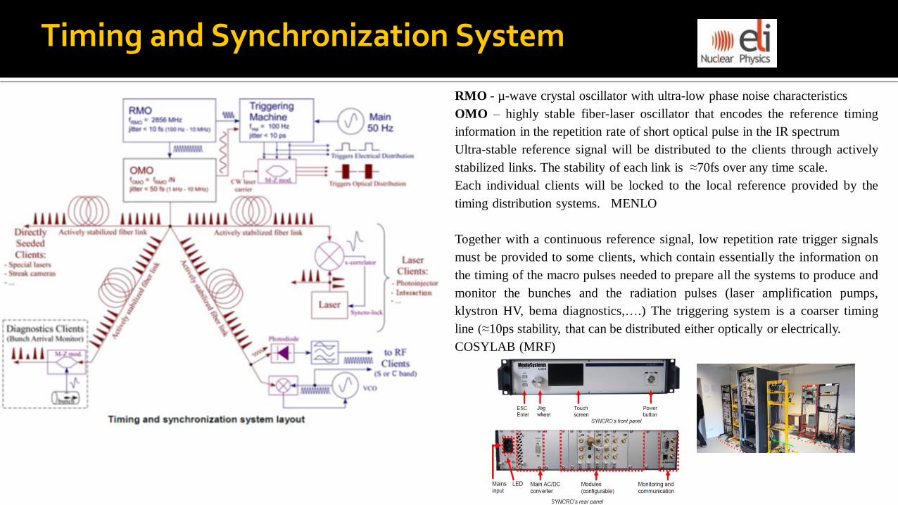
RMO - µ-wave crystal oscillator with ultra-low phase noise characteristics
OMO – highly stable fiber-laser oscillator that encodes the reference timing
information in the repetition rate of short optical pulse in the IR spectrum
Ultra-stable reference signal will be distributed to the clients through actively
stabilized links. The stability of each link is ≈70fs over any time scale.
Each individual clients will be locked to the local reference provided by the
timing distribution systems. MENLO
Together with a continuous reference signal, low repetition rate trigger signals
must be provided to some clients, which contain essentially the information on
the timing of the macro pulses needed to prepare all the systems to produce and
monitor the bunches and the radiation pulses (laser amplification pumps,
klystron HV, bema diagnostics,….) The triggering system is a coarser timing
line (≈10ps stability, that can be distributed either optically or electrically.
COSYLAB (MRF)
Timing and Synchronization System

Laser systems synchronization
The reference signal is generated by an optical master oscillator (OMO) and
transmitted to the end users by a stabilized fibre optic link.
The phase error is measured by optical mixing (cross-correlator). One pulse from
the laser oscillator and one from the OMO overlap. The measured phase noise
error is used to drive actuator to active control the oscillator’s cavity length ->
high frequency piezo-electric transducer (PZT) is associated to a lower frequency
stepper motor driven optical delay line.
Synchronization of the RF clients
RF driving signal for all power sources will
be locally extracted from the OMO reference
transported to each station by stabilized
phase links. The optical to electrical
conversion will be accomplished by
photodiodes. The same reference is used to
demodulate various RF pulses sampled over
the network, and the whole station is re-
phased in real time on the base of the
measured values.
Timing and Synchronization System

1. Nuclear Physics experiments
- Nuclear Resonance Fluorescence Experiments
- Photo-fission & Exotic Nuclei
- Photo-disintegration and Nuclear Astrophysics
(g,n) experiments; (g,p) experiments
2. Positron source for material science
3. Applications based on very brilliant 𝜸 beams
- Nuclear materials and radioactive waste
management (isotope-specific identification; scan
containers for nuclear materials and explosives)
- Food contamination
- Radioscopy and tomography (new methods for
producing medical radioisotopes for diagnostic
medical imaging and radiotherapy)
1. Laser–driven nuclear physics
2. Strong field QED
2. Irradiated materials sciences
1. Probing the Pair Creation from the
Vacuum in the Focus of Strong
Electrical Fields with a High Energy
𝜸 Beam
2. The Real Part of the Index of
Refraction of the Vacuum in High
Fields: Vacuum Birefringence
3. Cascades of e+e− Pairs and 𝜸 –
Rays triggered by a Single Slow
Electron in Strong Fields
GBS HPLS Experiments with GBS Experiments with HPLS
Combined experiments
Research Activities
4PIN – neutron 3He
counter array
Si DSSSD