exploiting usb devices with arduino-rev3 - black … · exploiting usb devices with arduino greg...
TRANSCRIPT

Exploiting USB Devices with Arduino Greg Ose – [email protected] Black Hat USA 2011

2
Abstract Hardware devices are continually relied upon to maintain a bridge between physical and virtual security. From access cards to OTP tokens, hardware devices receive limited review by application security professionals. They are often considered vastly more complex and difficult to assess than common web-‐‑ and network-‐‑based applications. In this talk I will cover a lightweight methodology to use when approaching the assessment of USB-‐‑based hardware devices. This will include the identification of trust boundaries and threat modeling, use case analysis though protocol analysis, as well as crafting a hardware device to exploit identified vulnerabilities. Not only will this methodology be described, it will be detailed through the assessment and exploitation of a hardware-‐‑based proximity sensor. Hardware-‐‑based proximity sensors attempt to enforce desktop security and lock a user’s desktop when the device has been removed from the vicinity of the computer. I will describe my experience and process for assessing a USB-‐‑based proximity sensor device and its eventual exploitation using components of the Arduino hardware architecture. I will describe the entire process not from the view of an electrical engineer, but from that of an application security professional with limited knowledge of current and voltage and a hobbyist’s budget.

3
Introduction In the world of application security assessments and pentests, web applications are king. Custom-‐‑developed applications by enterprises and service providers are more often than not exposed externally over HTTP, making them a prime target for security professionals to audit and external attackers to exploit. It is for this reason that the majority of any application security professional’s day, week, or month is spent in front of an HTTP proxy and a web browser. Standardized tools, methodologies, and vulnerabilities classes exist for these applications, even to the point where tools to automate the process claim to produce decent coverage and results. Application security professionals’ focus on web applications, combined with time, budget, and resources constraints rarely allow for opportunities to look beyond network-‐‑based threats and explore the world of hardware devices. However, greater consideration should be given to the assessment of hardware devices that are relied upon to enforce security controls. The transfer of sensitive information, defining the application’s trust boundaries, crosses not only externally from local hosts over a network connection but from the logical host to physical devices over wireless and physical connections. This architecture often does not consist of Ethernet, IP, or HTTP, introducing a perceived learning curve and hardware budget hurdle that needs to be overcome before assessment of these protocols can be performed. This whitepaper will demonstrate the applicability of already known and established assessment techniques and the use of low cost hardware to perform a security assessment of the commercially available ScreenKeeper USB device. Intended to lock a user’s desktop machine when the device senses it is out a range of the locked desktop, this device will be reviewed with a methodology familiar to any application security professional:
• Threat modeling o Identify the components of the underlying architecture o Identify security relevant use cases o Identify explicit and implicit trust boundaries
• Use Case Analysis o Identify the inputs and outputs of the enumerated use cases o Identify the protocol and methods for these inputs o Identify how security relevant use cases are executed

4
• Stimulus / Response Testing o Produce instrumentation to execute the identified use cases o Perform testing of the identified use cases with unexpected input to
yield unexpected output • Exploitation
o Instrumentation of any identified vulnerabilities o Automation of this exploitation
These steps will be demonstrated on the ScreenKeeper device using commodity and open source software, the low cost Arduino hardware platform, modifications of an open source USB stack for the Amtel ATmega8U2, and a limited knowledge of the USB protocol. Each step of this methodology will be presented with technical details of the ScreenKeeper device, culminating in the source code for a customized USB stack for the ATmega8U2 that will bypass the restrictions enforced by the ScreenKeeper device.
Outline This paper will present a device assessment methodology side-‐‑by-‐‑side with the technical details of an assessment of the ScreenKeeper device. The methodology will include threat modeling of the device’s architecture, its assumed trust boundaries, and enumerate the security-‐‑relevant use cases for the device. These use cases will be analyzed to identify their implementation within the device and expose any significant architectural flaws within the ScreenKeeper’s design. Inputs and outputs of the device related to these use cases will be enumerated and identified through stimulus / response testing instrumented with modifications to Arduino’s Amtel ATmega8U2 chip. This will include technical details of performing these steps using commodity hardware. Finally, the exploitation of the identified vulnerabilities will be detailed through the customization of the ATmega8U2 firmware to circumvent the device under review.
5
Threat Modeling The ScreenKeeper device is meant to provide physical security to desktop and laptop computers. When a user of the computer leaves the physical vicinity of the computer, the device will lock the user’s desktop and will subsequently unlock the desktop when the device is back in range of the physical computer. To implement this functionality, the ScreenKeeper architecture consists of three components:
• USB wireless receiver • Wireless token device • Host software
Typical installation and usage follows:
• User installs and runs the host software and configures an unlock password that can be used in place of the wireless token
• User inserts USB dongle into host computer • If the wireless token is out of range or turned off, the host screen is locked
and the underlying operating system and applications cannot be accessed • The host screen is unlocked if:
o The token is within range or o The previously configured password is provided
• The host screen will continue to be unlocked unless the token is turned off or moved out of range
Given this rather limited application lifecycle, the following security relevant use cases can be enumerated:
• Device installation and registration • Host screen lock • Host screen unlock via wireless token • Host screen unlock via password
The following trust boundaries are also assumed in this architecture
• Host to USB receiver • USB receiver to wireless token

6
It is also necessary to consider the physical nature of the device itself. Given implicit security requirements of the architecture, the wireless token is assumed to be uncompromised, as this is what authenticates the unlocking of the computer. However, malicious access to the physical computer and therefore the attached USB receiver needs to be identified as a potential attack vector.
Use Case Analysis For each of these use cases, specific questions were asked and analysis was performed to determine the implementation within the ScreenKeeper architecture. To answer these questions, USB traffic between the device and the host system was reviewed in combination with the analysis of changes and state within the host system.
Required Tools USB traffic analysis can be performed using open-‐‑source and commercially available software or hardware. On the tightest budget, traffic sent between the USB receiver and the host system can be captured using freely available tools. One inexpensive method to capture USB traffic utilizes VMWare virtual machines. Debugging logging of USB traffic can be enabled for analysis through the modification of configuration settings. To enable logging of USB traffic, the configuration of a VMWare image needs to be modified with the following options1:
monitor = "debug" usb.analyzer.enable = TRUE usb.analyzer.maxLine = 8192 mouse.vusb.enable = FALSE
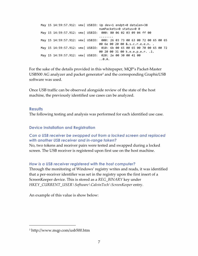
With these changes, the traffic of the USB device will be written to the vmware.log file. This log file can then be analyzed using the open source Virtual USB Analyzer2 software. Below is an illustration of a USB packet capture.
May 15 14:59:57.911: vmx| USBIO: GetDescriptor(string, 2, langId=0x0409) May 15 14:59:57.911: vmx| USBIO: Down dev=1 endpt=0 datalen=255
numPackets=0 status=390052272 1a54dbb0 May 15 14:59:57.911: vmx| USBIO: 000: 80 06 02 03 09 04 ff 00
........
1 http://vusb-‐‑analyzer.sourceforge.net/tutorial.html 2 http://vusb-‐‑analyzer.sourceforge.net/
7
May 15 14:59:57.912: vmx| USBIO: Up dev=1 endpt=0 datalen=38 numPackets=0 status=0 0
May 15 14:59:57.912: vmx| USBIO: 000: 80 06 02 03 09 04 ff 00 ........
May 15 14:59:57.912: vmx| USBIO: 000: 26 03 73 00 63 00 72 00 65 00 65 00 6e 00 20 00 &.s.c.r.e.e.n. .
May 15 14:59:57.912: vmx| USBIO: 010: 6b 00 65 00 65 00 70 00 65 00 72 00 20 00 31 00 k.e.e.p.e.r. .1.
May 15 14:59:57.912: vmx| USBIO: 020: 2e 00 30 00 41 00 ..0.A.
For the sake of the details provided in this whitepaper, MQP’s Packet-‐‑Master USB500 AG analyzer and packet generator3 and the corresponding GraphicUSB software was used. Once USB traffic can be observed alongside review of the state of the host machine, the previously identified use cases can be analyzed.
Results The following testing and analysis was performed for each identified use case.
Device Installation and Registration
Can a USB receiver be swapped out from a locked screen and replaced with another USB receiver and in-range token? No, two tokens and receiver pairs were tested and swapped during a locked screen. The USB receiver is registered upon first use on the host machine.
How is a USB receiver registered with the host computer? Through the monitoring of Windows’ registry writes and reads, it was identified that a per-‐‑receiver identifier was set in the registry upon the first insert of a ScreenKeeper device. This is stored as a REG_BINARY key under HKEY_CURRENT_USER\Software\CalvinTech\ScreenKeeper entry. An example of this value is show below:
3 http://www.mqp.com/usb500.htm

8
This is the Unicode of the string 4A33EF8E83.
What information is sent from the USB receiver when inserted into the host computer? The USB receiver follows the USB standard for registering using a USB Device Descriptor. The following information is provided by the device as part of registering as a HID-‐‑class device to the host computer: Field Value Meaning bLength 18 Valid Length bDescriptorType 1 DEVICE bcdUSB 0x0200 Spec Version bDeviceClass 0x00 Class Information in Interface
Description bDeviceSubClass 0x00 Class Information in Interface
Descriptor bDeviceProtocol 0x00 Class Information in Interface
Descriptor bMaxPacketSize0 32 Max EP0 Packet Size idVendor 0x1915 Nordic Semiconductor ASA idProject 0x001F Unknown bcdDevice 0x0100 Device Release Number iManufacturer 1 Index to Manufacturer String (Not
known) iProduct 2 Index to Product String “screen keeper

9
1.0A” iSerialNumber 3 Index to Serial Number String
“4A33EF8E83” bNumConfigurations 1 Number of Possible Configurations One interesting point to note is that the value sent for iSerialNumber in the device descriptor table is the same as our host’s registry entry.
Host Screen Lock
What USB traffic is sent when the wireless device is out of range or turned off to indicate that the screen should be locked? No traffic is sent over the registered USB device in this situation. It appears that the lack of USB traffic indicates that the device is out of range and the screen should be locked.
Does the host remain locked when the physical USB device is removed? Yes, the removal of the physical USB receiver does not unlock the host device.
Can the host be unlocked after the physical USB receiver has been removed and reinserted? Yes, through testing, it was identified that the device can be removed and reinserted. This introduces the possibility of an attacker compromising the USB receiver for a period of time and establishes that the USB receiver has to be assumed as compromised.
Host Screen Unlock via Token
What USB traffic is sent when the wireless device is in range? A HID Report inbound message is sent to the host every two seconds by the device. Typically, HID Report messages are sent structured in a way previously defined via HID Report Definition messages. However, the device is using these messages to transmit a static 24-‐‑byte identifier. This can be seen in the following analysis: When the wireless device was turned on and in-‐‑range, the following USB traffic was sent:

10
If the device was turned off or was not in range, no USB traffic was sent from the receiver. Finally, if the device was then re-‐‑activated or returned to range, the following traffic was sent:
How is this unique identifier stored / verified? It is stored in the registry, the full contents of the data of this packet is shown below: Offset ASCII 000: 34 00 41 00 33 00 45 00 46 00 38 00 45 00 4.A.3.3.E.F.8.E 010: 38 00 33 00 30 00 31 00 8.3.0.1.
This is the same value that was stored within the serial registry entry appended with a trailing 01 Unicode string.
How is this unique identifier generated or initially registered? It is per device, if we look at the device descriptor table it is the same as used as the device serial number in the initial device descriptor table.

11
Host Screen Unlock via Password
How is this user-supplied password stored? This value is also stored within the registry. It appears to not be stored in plaintext, but as an encrypted format that is the same length as the plaintext password. While this is likely done in an insecure manner, under typical scenarios, this registry entry would not be obtainable from an external attacker.
Conclusion With this analysis one can derive a number of details about how trust is established between the USB device and the host computer. Each USB device registers with a unique serial number that is sent as part of the USB device descriptor table. When the device is in range, this serial number is sent as the data of a HID Report message, indicating to the host software to keep the computer unlocked. When this message is not sent, the software locks the computer. Based on this knowledge, we can conclude an external attacker can obtain the unique serial number registered with the host. Using this serial number we can spoof the registered device by sending an identical device descriptor table. As a registered device we can send the expected message, the serial number, and unlock the target host computer.
Stimulus / Response Testing In the previous step, we identified the use case to unlock and lock is controlled completely via USB traffic to and from the USB receiver. The USB receiver not only contains the unique identifier required to unlock the host computer, it also provides the mechanism for which this request is sent to the host computer. We now need to instrument two steps to generate and replay the input that triggers the unlock functionality within the host software:
1. Register a USB device with the host that matches the expected configuration and identification of the ScreenKeeper USB receiver
2. Submit a USB HID Report message with the required data
Required Tools To properly submit valid messages to the host USB bus, we need to either provide or emulate a USB device to the target host computer. Again, on to

12
smallest of budgets, this can be accomplished by utilizing the low-‐‑cost Arduino hardware architecture. The latest revision of the Arduino hardware, the Arduino Uno, replaces previous generations’ FTDI USB-‐‑to-‐‑serial chip with the Amtel ATmega8U24. This chip allows much more flexibility and customization through the ability to modify the firmware though the USB Device Firmware Upgrade (DFU) standard. Furthermore, the open-‐‑source Lightweight USB Framework for AVRs (LUFA) library5 provides the base of the firmware for the ATmega8U2 used by Arduino. The source for this library can be downloaded, modified, and re-‐‑flashed on the Arduino’s ATmega8U2. This will provide a simple method of registering and submitting traffic as a USB device. The following steps can be taken to modify the device descriptors and traffic sent by the ATmega8U2 of the Arduino device.
Create firmware compilation environment for the ATmega8U2 The following source libraries will need to be downloaded to properly flash the ATmega8U2.
1. Download the 100807 version of the LUFA firmware 2. Download the Arduino source code6. This contains the LUFA
implementation used for the Arduino’s USB-‐‑to-‐‑serial firmware. Copy the /hardware/arduino/firmwares/arduino-‐‑usbserial source directory from the Arduino source to the LUFA source tree under the Project directory. To cross-‐‑compile the LUFA firmware and flash it to the ATmega8U2 chip, the following tools are also required:
• dfu-‐‑programmer7 • A AVR GNU compiler suite –
o AVR CrossPack for OSX8
4 http://arduino.cc/en/Main/ArduinoBoardUno 5 http://www.fourwalledcubicle.com/LUFA.php 6 http://www.arduino.cc/en/Main/Software 7 http://dfu-‐‑programmer.sourceforge.net/ 8 http://www.obdev.at/products/crosspack/index.html

13
o Others toolchains exist for Linux and Windows9
With these tools configured, the Arduino USB-‐‑to-‐‑serial firmware from the LUFA library can be compiled with a simple make command in the arduino-‐‑usbserial directory.
Flashing the ATmega8U2 To test and ensure that the firmware image was properly built, the arduino-‐‑usbserial.hex file can be flashed to the ATmega8U2 using the following steps.10
• Set the ATmega8U2 on the Arduino to DFU mode o Hold the bottom left pin of the ATmega8U2 to ground o Hold ground to the bottom lead of the capacitor above the
oscillator o These two spots have been highlighted in the image below o This will cause the Arduino’s LED to blink and then enumerate the
Arduino’s USB as an Arduino Uno DFU o Remove all connections
• Run make dfu to use dfu-‐‑programmer to flash the ATmega8U2 • Remove and reinsert the USB connection to the host • The device should enumerate again as an Arduino Uno
9 http://www.atmel.com/dyn/products/tools_card.asp?tool_id=4118 10 http://arduino.cc/forum/index.php?topic=111.0

14
Customizing Firmware With the ability to compile and re-‐‑flash the ATmega8U2, a custom firmware can be created. Two main files are of interest when modifying the firmware.
Descriptors.c This file contains the data that is used when creating the USB Device Descriptor messages. These can be modified to match the enumeration of our target device.
Arduino-usbserial.c This file contains the source of what is actually executed by the USB device. The main function is just that, the entry point for the program. This includes a routine to setup the hardware and a loop that handles the actual protocol of the device. With the ability to create a custom firmware to dictate the device’s enumeration and output, we can instrument stimulus and response testing the same as if we were testing a traditional web-‐‑ or network-‐‑based application.
Exploitation Given our ability to change the device descriptor used to enumerate our modified ATmega8U2 chip and to control the messages sent by this device, it is possible to program the ATmega8U2 to masquerade as a registered ScreenKeeper device and unlock the targeted host computer. The following steps were taken to exploit the ScreenKeeper device.
Obtain Device Serial Number Since the USB device serial number is used as the unique serial number to unlock the host, the following steps can be utilized to obtain the serial number.
1. Remove the ScreenKeeper device from target host computer 2. Insert ScreenKeeper device into attacker controlled host 3. Use system_profiler or equivalent system tools to obtain the USB serial
number descriptor Under OSX, this process is shown below:
$ system_profiler SPUSBDataType | grep 'screen keeper' -‐A 10 screen keeper 1.0A: Product ID: 0x001f Vendor ID: 0x1915 (Nordic Semiconductor ASA)

15
Version: 1.00 Serial Number: 4A33EF8E83 Speed: Up to 12 Mb/sec Manufacturer: SEMI-‐LINK Location ID: 0x04100000 Current Available (mA): 500 Current Required (mA): 100
The device descriptor tables of the ATmega8U2 then need to be updated to reflect the descriptors of the ScreenKeeper device. The changes to Descriptors.c and Arduino-‐‑screenkeeper.c in the Arduino ScreenKeeper source code fully identify these changes. The following high-‐‑level changes were made to the Arduino firmware source.
Descriptors.c Update the device information string references to be identical to that of the ScreenKeeper device. The additional SerialNum descriptor can be added as an index in the DeviceDescriptor struct, a new PROGMEM string reference added as a USB_Descriptor_String_t and a new DTYPE_String case statement added to the CALLBACK_USB_GetDescriptor function to properly set the descriptor string’s address and size.
Arduino-screenkeeper.c The main function was modified to write the given serial number to the enumerated endpoint in an infinite loop. This was done using the Endpoint_Write_PStream_LE11 function from the LUFA library and is shown below. int main(void) { SetupHardware(); sei(); for (;;) { Endpoint_Write_PStream_LE((void*)&SerialNumberString.UnicodeString,
USB_STRING_LEN(SERIAL_NUMBER_LEN)+4, NO_STREAM_CALLBACK); Endpoint_ClearIN(); HID_Device_USBTask(&Generic_HID_Interface); USB_USBTask(); } }
11 http://www.fourwalledcubicle.com/files/LUFA/Doc/091122/html/a00265.html
16
By obtaining the USB serial number from the ScreenKeeper device, flashing the Arduino device with this serial number and updated code to send the serial number and modified device descriptors, an attack could easily compromise any host protected by the ScreenKeeper device.

17
Conclusion Due to the trust boundaries of the ScreenKeeper architecture, it is possible to completely bypass the security provided by the device. The physically attached and potentially compromised USB receiver contains the information required to authenticate and unlock the protected desktop. Additionally, there are no restrictions on obtaining this information if the USB receiver is compromised. Due to this vulnerability, it is trivial to craft a malicious device to emulate the required actions and compromise the protected host.