expert machinist help topic collection - · pdf filepro/engineer ® wildfire™ 2.0...
TRANSCRIPT

Pro/ENGINEER®
Wildfire™ 2.0
Expert Machinist®
Help Topic Collection
Parametric Technology Corporation
Copyright © 2004 Parametric Technology Corporation. All Rights Reserved.
User and training documentation from Parametric Technology Corporation (PTC) is subject to the copyright laws of the
United States and other countries and is provided under a license agreement that restricts copying, disclosure, and use
of such documentation. PTC hereby grants to the licensed user the right to make copies in printed form of this
documentation if provided on software media, but only for internal/personal use and in accordance with the license
agreement under which the applicable software is licensed. Any copy made shall include the PTC copyright notice and
any other proprietary notice provided by PTC. This documentation may not be disclosed, transferred, modified, or
reduced to any form, including electronic media, or transmitted or made publicly available by any means without the
prior written consent of PTC and no authorization is granted to make copies for such purposes.
Information described herein is furnished for general information only, is subject to change without notice, and should
not be construed as a warranty or commitment by PTC. PTC assumes no responsibility or liability for any errors or
inaccuracies that may appear in this document.
The software described in this document is provided under written license agreement, contains valuable trade secrets
and proprietary information, and is protected by the copyright laws of the United States and other countries. It may not
be copied or distributed in any form or medium, disclosed to third parties, or used in any manner not provided for in the
software licenses agreement except with written prior approval from PTC. UNAUTHORIZED USE OF SOFTWARE
OR ITS DOCUMENTATION CAN RESULT IN CIVIL DAMAGES AND CRIMINAL PROSECUTION.
Registered Trademarks of Parametric Technology Corporation or a Subsidiary Advanced Surface Design, Behavioral Modeling, CADDS, Computervision, CounterPart, EPD, EPD.Connect,
Expert Machinist, Flexible Engineering, HARNESSDESIGN, Info*Engine, InPart, MECHANICA, Optegra,
Parametric Technology, Parametric Technology Corporation, PartSpeak, PHOTORENDER, Pro/DESKTOP, Pro/E,
Pro/ENGINEER, Pro/HELP, Pro/INTRALINK, Pro/MECHANICA, Pro/TOOLKIT, Product First, PTC, PT/Products,
Shaping Innovation, and Windchill.
Trademarks of Parametric Technology Corporation or a Subsidiary 3DPAINT, Associative Topology Bus, AutobuildZ, CDRS, Create � Collaborate � Control, CV, CVact, CVaec,
CVdesign, CV-DORS, CVMAC, CVNC, CVToolmaker, DataDoctor, DesignSuite, DIMENSION III, DIVISION,
e/ENGINEER, eNC Explorer, Expert MoldBase, Expert Toolmaker, GRANITE, ISSM, KDiP,
Knowledge Discipline in Practice, Knowledge System Driver, ModelCHECK, MoldShop, NC Builder, Pro/ANIMATE,
Pro/ASSEMBLY, Pro/CABLING, Pro/CASTING, Pro/CDT, Pro/CMM, Pro/COLLABORATE, Pro/COMPOSITE,
Pro/CONCEPT, Pro/CONVERT, Pro/DATA for PDGS, Pro/DESIGNER, Pro/DETAIL, Pro/DIAGRAM,
Pro/DIEFACE, Pro/DRAW, Pro/ECAD, Pro/ENGINE, Pro/FEATURE, Pro/FEM-POST, Pro/FICIENCY,
Pro/FLY-THROUGH, Pro/HARNESS, Pro/INTERFACE, Pro/LANGUAGE, Pro/LEGACY, Pro/LIBRARYACCESS,
Pro/MESH, Pro/Model.View, Pro/MOLDESIGN, Pro/NC-ADVANCED, Pro/NC-CHECK, Pro/NC-MILL,
Pro/NCPOST, Pro/NC-SHEETMETAL, Pro/NC-TURN, Pro/NC-WEDM, Pro/NC-Wire EDM,
Pro/NETWORK ANIMATOR, Pro/NOTEBOOK, Pro/PDM, Pro/PHOTORENDER, Pro/PIPING,
Pro/PLASTIC ADVISOR, Pro/PLOT, Pro/POWER DESIGN, Pro/PROCESS, Pro/REPORT, Pro/REVIEW,
Pro/SCAN-TOOLS, Pro/SHEETMETAL, Pro/SURFACE, Pro/VERIFY, Pro/Web.Link, Pro/Web.Publish,
Pro/WELDING, Product Development Means Business, ProductView, PTC Precision, Shrinkwrap,
Simple � Powerful � Connected, The Product Development Company, The Way to Product First, Wildfire,
Windchill DynamicDesignLink, Windchill PartsLink, Windchill PDMLink, Windchill ProjectLink, and
Windchill SupplyLink.
Patents of Parametric Technology Corporation or a Subsidiary Registration numbers and issue dates follow. Additionally, equivalent patents may be issued or pending outside of the
United States. Contact PTC for further information. 6,665,569 B1 16-December-2003
6,625,607 B1 23-September-2003
6,580,428 B1 17-June-2003
GB2354684B 02-July-2003
GB2384125 15-October-2003
GB2354096 12-November-2003
6,608,623 B1 19 August 2003
GB2353376 05-November-2003
GB2354686 15-October-2003
6,545,671 B1 08-April-2003
GB2354685B 18-June-2003
6,608,623 B1 19 August 2003
6,473,673 B1 29-October-2002
GB2354683B 04-June-2003
6,447,223 B1 10-Sept-2002
6,308,144 23-October-2001
5,680,523 21-October-1997
5,838,331 17-November-1998
4,956,771 11-September-1990
5,058,000 15-October-1991
5,140,321 18-August-1992
5,423,023 05-June-1990
4,310,615 21-December-1998
4,310,614 30-April-1996
4,310,614 22-April-1999
5,297,053 22-March-1994
5,513,316 30-April-1996
5,689,711 18-November-1997
5,506,950 09-April-1996
5,428,772 27-June-1995
5,850,535 15-December-1998
5,557,176 09-November-1996
5,561,747 01-October-1996
Third-Party Trademarks
Adobe is a registered trademark of Adobe Systems. Advanced ClusterProven, ClusterProven, and the ClusterProven
design are trademarks or registered trademarks of International Business Machines Corporation in the United States
and other countries and are used under license. IBM Corporation does not warrant and is not responsible for the

operation of this software product. AIX is a registered trademark of IBM Corporation. Allegro, Cadence, and Concept
are registered trademarks of Cadence Design Systems, Inc. Apple, Mac, Mac OS, and Panther are trademarks or
registered trademarks of Apple Computer, Inc. AutoCAD and Autodesk Inventor are registered trademarks of
Autodesk, Inc. Baan is a registered trademark of Baan Company. CADAM and CATIA are registered trademarks of
Dassault Systemes. COACH is a trademark of CADTRAIN, Inc. DOORS is a registered trademark of Telelogic AB.
FLEXlm is a trademark of Macrovision Corporation. Geomagic is a registered trademark of Raindrop Geomagic, Inc.
EVERSYNC, GROOVE, GROOVEFEST, GROOVE.NET, GROOVE NETWORKS, iGROOVE, PEERWARE, and
the interlocking circles logo are trademarks of Groove Networks, Inc. Helix is a trademark of Microcadam, Inc.
HOOPS is a trademark of Tech Soft America, Inc. HP-UX is a registered trademark and Tru64 is a trademark of the
Hewlett-Packard Company. I-DEAS, Metaphase, Parasolid, SHERPA, Solid Edge, and Unigraphics are trademarks or
registered trademarks of Electronic Data Systems Corporation (EDS). InstallShield is a registered trademark and
service mark of InstallShield Software Corporation in the United States and/or other countries. Intel is a registered
trademark of Intel Corporation. IRIX is a registered trademark of Silicon Graphics, Inc. LINUX is a registered
trademark of Linus Torvalds. MatrixOne is a trademark of MatrixOne, Inc. Mentor Graphics and Board Station are
registered trademarks and 3D Design, AMPLE, and Design Manager are trademarks of Mentor Graphics Corporation.
MEDUSA and STHENO are trademarks of CAD Schroer GmbH. Microsoft, Microsoft Project, Windows, the
Windows logo, Windows NT, Visual Basic, and the Visual Basic logo are registered trademarks of
Microsoft Corporation in the United States and/or other countries. Netscape and the Netscape N and Ship's Wheel
logos are registered trademarks of Netscape Communications Corporation in the U.S. and other countries. Oracle is a
registered trademark of Oracle Corporation. OrbixWeb is a registered trademark of IONA Technologies PLC. PDGS is
a registered trademark of Ford Motor Company. RAND is a trademark of RAND Worldwide. Rational Rose is a
registered trademark of Rational Software Corporation. RetrievalWare is a registered trademark of Convera
Corporation. RosettaNet is a trademark and Partner Interface Process and PIP are registered trademarks of
“RosettaNet,” a nonprofit organization. SAP and R/3 are registered trademarks of SAP AG Germany. SolidWorks is a
registered trademark of SolidWorks Corporation. All SPARC trademarks are used under license and are trademarks or
registered trademarks of SPARC International, Inc. in the United States and in other countries. Products bearing
SPARC trademarks are based upon an architecture developed by Sun Microsystems, Inc. Sun, Sun Microsystems, the
Sun logo, Solaris, UltraSPARC, Java and all Java based marks, and “The Network is the Computer” are trademarks or
registered trademarks of Sun Microsystems, Inc. in the United States and in other countries. TIBCO, TIBCO Software,
TIBCO ActiveEnterprise, TIBCO Designer, TIBCO Enterprise for JMS, TIBCO Rendezvous, TIBCO Turbo XML,
TIBCO Business Works are the trademarks or registered trademarks of TIBCO Software Inc. in the United States and
other countries. WebEx is a trademark of WebEx Communications, Inc.
Third-Party Technology Information Certain PTC software products contain licensed third-party technology: Rational Rose 2000E is copyrighted software
of Rational Software Corporation. RetrievalWare is copyrighted software of Convera Corporation. VisTools library is
copyrighted software of Visual Kinematics, Inc. (VKI) containing confidential trade secret information belonging to
VKI. HOOPS graphics system is a proprietary software product of, and is copyrighted by, Tech Soft America, Inc.
G-POST is copyrighted software and a registered trademark of Intercim. VERICUT is copyrighted software and a
registered trademark of CGTech. Pro/PLASTIC ADVISOR is powered by Moldflow technology. Moldflow is a
registered trademark of Moldflow Corporation. The JPEG image output in the Pro/Web.Publish module is based in part
on the work of the independent JPEG Group. DFORMD.DLL is copyrighted software from Compaq Computer
Corporation and may not be distributed. METIS, developed by George Karypis and Vipin Kumar at the University of
Minnesota, can be researched at http://www.cs.umn.edu/~karypis/metis. METIS is © 1997 Regents of the University of
Minnesota. LightWork Libraries are copyrighted by LightWork Design 1990–2001. Visual Basic for Applications and
Internet Explorer is copyrighted software of Microsoft Corporation. Parasolid © Electronic Data Systems (EDS).
Windchill Info*Engine Server contains IBM XML Parser for Java Edition and the IBM Lotus XSL Edition. Pop-up
calendar components Copyright © 1998 Netscape Communications Corporation. All Rights Reserved.
TECHNOMATIX is copyrighted software and contains proprietary information of Technomatix Technologies Ltd.
Technology "Powered by Groove" is provided by Groove Networks, Inc. Technology "Powered by WebEx" is provided
by WebEx Communications, Inc. Oracle 8i run-time and Oracle 9i run-time, Copyright © 2002–2003 Oracle
Corporation. Oracle programs provided herein are subject to a restricted use license and can only be used in
conjunction with the PTC software they are provided with. Apache Server, Tomcat, Xalan, and Xerces are technologies
developed by, and are copyrighted software of, the Apache Software Foundation (http://www.apache.org) – their use is
subject to the terms and limitations at: http://www.apache.org/LICENSE.txt. Acrobat Reader is copyrighted software of
Adobe Systems Inc. and is subject to the Adobe End-User License Agreement as provided by Adobe with those
products. UnZip (© 1990-2001 Info-ZIP, All Rights Reserved) is provided “AS IS” and WITHOUT WARRANTY OF
ANY KIND. For the complete Info-ZIP license see ftp://ftp.info-zip.org/pub/infozip/license.html. Gecko and Mozilla
components are subject to the Mozilla Public License Version 1.1 at http://www.mozilla.org/MPL. Software distributed
under the MPL is distributed on an "AS IS" basis, WITHOUT WARRANTY OF ANY KIND, either expressed or
implied. See the MPL for the specific language governing rights and limitations. The Java™ Telnet Applet
(StatusPeer.java, TelnetIO.java, TelnetWrapper.java, TimedOutException.java), Copyright © 1996, 97 Mattias L.
Jugel, Marcus Meißner, is redistributed under the GNU General Public License. This license is from the original
copyright holder and the Applet is provided WITHOUT WARRANTY OF ANY KIND. You may obtain a copy of the
source code for the Applet at http://www.mud.de/se/jta (for a charge of no more than the cost of physically performing
the source distribution), by sending e-mail to [email protected] or [email protected]—you are allowed to choose either
distribution method. The source code is likewise provided under the GNU General Public License. GTK+The GIMP
Toolkit are licensed under the GNU LGPL. You may obtain a copy of the source code at http://www.gtk.org, which is
likewise provided under the GNU LGPL. zlib software Copyright © 1995-2002 Jean-loup Gailly and Mark Adler.
OmniORB is distributed under the terms and conditions of the GNU General Public License and GNU Library General
Public License. The Java Getopt.jar, copyright 1987-1997 Free Software Foundation, Inc.; Java Port copyright 1998 by
Aaron M. Renn ([email protected]), is redistributed under the GNU LGPL. You may obtain a copy of the
source code at http://www.urbanophile.com/arenn/hacking/download.html. The source code is likewise provided under
the GNU LGPL. Mozilla Japanese localization components are subject to the Netscape Public License Version 1.1 (at
http://www.mozilla.org/NPL). Software distributed under NPL is distributed on an "AS IS" basis, WITHOUT
WARRANTY OF ANY KIND, either expressed or implied (see the NPL for the specific language governing rights and
limitations). The Original Code is Mozilla Communicator client code, released March 31, 1998 and the Initial
Developer of the Original Code is Netscape Communications Corporation. Portions created by Netscape are Copyright
© 1998 Netscape Communications Corporation. All Rights Reserved. Contributors: Kazu Yamamoto
([email protected]), Ryoichi Furukawa ([email protected]), Tsukasa Maruyama ([email protected]), Teiji Matsuba
UNITED STATES GOVERNMENT RESTRICTED RIGHTS LEGEND
This document and the software described herein are Commercial Computer Documentation and Software, pursuant to
FAR 12.212(a)-(b) (OCT’95) or DFARS 227.7202-1(a) and 227.7202-3(a) (JUN’95), is provided to the US
Government under a limited commercial license only. For procurements predating the above clauses, use, duplication,
or disclosure by the Government is subject to the restrictions set forth in subparagraph (c)(1)(ii) of the Rights in
Technical Data and Computer Software Clause at DFARS 252.227-7013 (OCT’88) or Commercial Computer
Software-Restricted Rights at FAR 52.227-19(c)(1)-(2) (JUN’87), as applicable. 012304
Parametric Technology Corporation, 140 Kendrick Street, Needham, MA 02494 USA
v
Table Of Contents Using Additional Modules ................................................................................. 1
NC Machining Option .................................................................................... 1
Expert Machinist ....................................................................................... 1
About Expert Machinist.................................................................................... 1
Modal Settings............................................................................................. 2
To Create a Machining Process ......................................................................... 2
To Retrieve a Machining Process ....................................................................... 2
To Create a New NC Model............................................................................... 3
No Stock Machining ........................................................................................ 3
The NC MODEL Menu Commands ...................................................................... 5
Tip: Creating NC Models .................................................................................. 5
To Replace a Reference Model .......................................................................... 6
Part Family Tables in Expert Machinist ............................................................... 6
About Configuration File Options....................................................................... 6
To Set Expert Machinist Configuration Options.................................................... 7
assy_mfg_open_mode .................................................................................... 7
freeform_toolpath_matrem .............................................................................. 7
mfg_template_dir ........................................................................................... 7
ncmdl_bar_stock_part_path............................................................................. 8
ncmdl_billet_stock_part_path........................................................................... 8
pro_mf_tprm_dir ............................................................................................ 8
template_mfgemo .......................................................................................... 8
To Create Stock.............................................................................................. 8
The Create Stock Dialog Box ............................................................................ 9
Example: Creating a Default Billet....................................................................11
Example: Modifying the Standard Stock Sizes....................................................13
To Modify Stock Allowances ............................................................................14
To Modify Stock Outline..................................................................................15
To Create an Operation ..................................................................................16
Table Of Contents
vi
The Operation Setup Dialog Box ......................................................................16
To Define Program Zero .................................................................................18
Program Zero Usage ......................................................................................19
Z-axis Orientation.......................................................................................20
To Create a Machine Tool................................................................................20
Machine Tool Settings ....................................................................................21
To Set Up a PPRINT Table ...............................................................................24
The PPRINT Table ..........................................................................................25
About Fixtures...............................................................................................27
To Create a Fixture Setup ...............................................................................27
The Fixture Setup Dialog Box ..........................................................................28
To Activate a Fixture Setup .............................................................................29
To Modify a Fixture Setup ...............................................................................29
To Delete a Fixture Setup ...............................................................................30
Tips: Using Fixture Setups ..............................................................................30
About Setting Up Tools...................................................................................30
To Set Up Cutting Tools ..................................................................................31
The Tool Setup Dialog Box ..............................................................................31
To Set Up the Material Directory Structure ........................................................33
Example: Setting Up the Material Directory Structure .........................................33
To Add a New Tool.........................................................................................34
To Specify the Cutting Data for the Tool ...........................................................34
To Provide the Bill of Materials for the Tool........................................................35
To Retrieve Tool Parameters ...........................................................................36
To Add a Sketched Tool ..................................................................................36
To Modify an Existing Tool ..............................................................................37
To Delete a Tool ............................................................................................37
To Save Tool Parameters ................................................................................37
To Create a Tool Model...................................................................................37
Solid Tool Models...........................................................................................38
Standard Library.........................................................................................38
Table Of Contents
vii
To Use a Tool Model.......................................................................................38
Using Assembly as a Tool Model ......................................................................39
About Machining Features...............................................................................39
To Create a Machining Feature ........................................................................41
Creating Machining Features for No Stock Machining ..........................................41
To Adjust Feature Boundaries..........................................................................42
Example: Adjusting Feature Boundaries............................................................42
To Adjust Soft Walls.......................................................................................46
To Adjust Feature Depth.................................................................................46
To Adjust Feature Top ....................................................................................46
To Machine a Feature .....................................................................................47
To Set Tool Path Properties .............................................................................48
Automatic Placement of CL Commands .............................................................49
To Mimic a Tool Path ......................................................................................49
To Create a Face Feature................................................................................50
To Machine a Face Feature..............................................................................51
The Face Milling Dialog Box.............................................................................52
Example: Face Machining................................................................................53
To Create a Slab Feature ................................................................................53
Example: Creating a Slab Feature ....................................................................54
To Machine a Slab Feature ..............................................................................55
The Slab Milling Dialog Box .............................................................................56
To Create a Pocket Feature .............................................................................58
To Machine a Pocket Feature...........................................................................58
The Pocket Milling Dialog Box ..........................................................................59
To Create a Through Pocket Feature.................................................................61
Example: Creating a Through Pocket................................................................62
To Machine a Through Pocket Feature ..............................................................63
The Through Pocket Milling Dialog Box .............................................................64
To Create a Step Feature................................................................................65
To Machine a Step Feature..............................................................................66

Table Of Contents
viii
The Step Milling Dialog Box.............................................................................67
To Create a Profile Feature..............................................................................69
To Machine a Profile Feature ...........................................................................70
The Profile Milling Dialog Box ..........................................................................71
To Create a Channel Feature ...........................................................................72
Example: Creating a Channel Feature...............................................................73
To Machine a Channel Feature.........................................................................73
The Channel Milling Dialog Box........................................................................74
Example: Channel Machining...........................................................................76
To Create a Slot Feature.................................................................................77
To Machine a Slot Feature...............................................................................78
The Slot Milling Dialog Box..............................................................................79
To Create a Through Slot Feature ....................................................................80
To Machine a Through Slot Feature ..................................................................81
The Through Slot Milling Dialog Box .................................................................82
To Create a Boss Top Feature..........................................................................84
Example: Creating a Boss Top Feature .............................................................84
To Machine a Boss Top Feature........................................................................86
The Boss Top Milling Dialog Box.......................................................................87
Example: Boss Top Machining .........................................................................88
To Create a Flange Feature .............................................................................90
Example: Creating a Flange Feature.................................................................90
To Machine a Flange Feature ...........................................................................91
The Flange Milling Dialog Box ..........................................................................92
To Create an O-Ring Feature...........................................................................94
To Machine an O-Ring Feature.........................................................................94
The O-Ring Milling Dialog Box..........................................................................95
Example: O-Ring Machining ............................................................................96
To Create a Rib Top Feature............................................................................97
Example: Creating a Rib Top Feature ...............................................................98
To Machine a Rib Top Feature........................................................................100
Table Of Contents
ix
The Rib Top Milling Dialog Box.......................................................................101
Example: Rib Top Machining .........................................................................102
Example: Open Rib Top Machining .................................................................103
To Create an Undercut Feature......................................................................104
Example: Creating an Undercut .....................................................................105
To Machine an Undercut Feature....................................................................107
The Undercut Milling Dialog Box.....................................................................108
Using the Side Mill Tool ................................................................................110
Example: Machining an Undercut ...................................................................112
To Create a Top Chamfer Feature ..................................................................113
Example: Creating a Top Chamfer Feature ......................................................114
To Machine a Top Chamfer Feature ................................................................116
The Top Round/Chamfer Milling Dialog Box .....................................................117
Using the Chamfering Tool ............................................................................118
To Create a Top Round Feature .....................................................................121
Example: Creating a Top Round Feature .........................................................122
To Machine a Top Round Feature ...................................................................124
The Top Round/Chamfer Milling Dialog Box .....................................................125
Using the Corner Rounding Tool.....................................................................126
Example: Top Round Machining .....................................................................127
To Create a Hole Group Feature.....................................................................128
Combining Selection Methods........................................................................128
To Select Holes by Axes................................................................................129
To Select Holes by Diameters ........................................................................129
To Select Holes by Surfaces ..........................................................................129
To Select Holes by Feature Parameters...........................................................129
To Machine a Hole Group Feature ..................................................................130
The Drilling Strategy Dialog Box ....................................................................131
Example: Automatic Chamfer Machining .........................................................134
To Create an Entry Hole Feature ....................................................................135
The Entry Hole Dialog Box ............................................................................136
Table Of Contents
x
To Machine an Entry Hole Feature..................................................................137
To Machine a Free Form Feature....................................................................138
The Freeform Milling Dialog Box.....................................................................139
About Displaying the Tool Path ......................................................................141
To Display the Tool Path ...............................................................................141
The PLAY PATH Dialog Box............................................................................142
To Add a Break Point....................................................................................143
Manipulating Break Points.............................................................................143
To Position the Tool .....................................................................................144
To Insert a CL Command ..............................................................................144
Using Parameters in CL Commands ................................................................145
To Delete a CL Command .............................................................................145
To Redefine a CL Command ..........................................................................145
To Save CL Data in a File ..............................................................................146
To Output a CL File ......................................................................................146
To Output NC Codes.....................................................................................146
About the Template Manager ........................................................................147
To Create a New Template............................................................................148
To Convert an Existing TPL Template File to XML Format...................................149
To Place a Template.....................................................................................149
To Manipulate Features Using the Model Tree ..................................................150
Options Available from the Model Tree............................................................150
To Toggle Material Display ............................................................................152
Index.........................................................................................................155
1
Using Additional Modules
NC Machining Option
Expert Machinist
Using Expert Machinist
About Expert Machinist
A typical Expert Machinist process may contain the following basic steps:
1. Set up the NC Model. Bring in the reference model and create stock.
2. Set up the database. It may contain such items as machine tools, cutting tools,
fixture configurations, or machining templates. This step is optional. If you do not
want to set up all your database first, you can go directly into the machining
process and later define any of the items above when you actually need them.
3. Define an operation. An operation setup may contain the following elements:
o Operation name
o Machine tool
o Program Zero (coordinate system for CL output)
o Stock material specification
o Fixture setup
o FROM and HOME points
o Names used in Cutter Location (CL) data output and PPRINT
o Operation comments
You have to define a machine tool and a Program Zero coordinate system before
you can start creating machining features. Other setup elements are optional.
4. Define the machining features for the specified operation. Machining features
establish what material needs to be removed from the stock to achieve the
reference model geometry. Each closed volume of material to be removed
comprises a separate machining feature.
Define the machining features in the order you want them machined (one
exception: create an Entry Hole feature after you have created the closed feature
for which you need it). As you define machining features, the system allocates
the appropriate material to be removed, and calculates the subsequent feature
geometry based on existing machining features.
5. Create tool paths for each machining feature. Once the features are defined, you
can machine them, that is, create the appropriate tool paths, at any time and in
any order. You can also machine the features by applying predefined machining
Expert Machinist – Help Topic Collection
2
templates. These templates represent certain frequently used machining
strategies; each strategy contains a complete set of the machining options and
values that you would normally define when machining a feature.
6. After you have defined all the machining features and created the appropriate
tool paths, output the complete operation to a CL file and postprocess it, or
output the tool path data directly in the MCD format.
Modal Settings
Most of the machining setup elements are modal: that is, all subsequent machining
features will use this setting until you explicitly change it. Among those are:
• Operation setup (including the machine tool and Program Zero coordinate
system)
• Tool (provided the tool type is compatible with the machining feature type)
• Program Zero coordinate system within the machining feature (for the first
machining feature, the Program Zero coordinate system specified at the time of
setting up the operation will be implicitly used, unless you explicitly specify
another one)
To Create a Machining Process
1. On the Pro/ENGINEER menu bar, click File > New (or click ). The New
dialog box opens.
2. Select the Manufacturing option under Type.
3. Select the Expert Machinist option under Sub-Type.
4. Unless you want to accept the default, type a name for the new machining
process in the Name text box.
5. Click OK.
6. The system displays the Model Tree and adds the Expert Machinist-specific
menus to the Pro/ENGINEER menu bar. Use the NC Setup menu commands to
define the NC model and the operation.
To Retrieve a Machining Process
1. On the Pro/ENGINEER menu bar, click File > Open (or click ). The browser
window opens.
2. By default, all files are listed in the browser window. To narrow the search,
choose Manufacturing from the Type drop-down list. The browser window then
lists all the process files in the Manufacturing family of products, that is, all the
objects that have the .mfg extension (including Cast, Mold, Sheet Metal
manufacturing, and so on). If you have various types of manufacturing
processes, and want to filter out inapplicable types, select NC Assembly from
Using Additional Modules
3
the Sub-type list. The browser window then lists all the Assembly manufacturing
models, both for the Expert Machinist and Pro/NC processes.
3. Select the name of the process to retrieve from the browser window.
The system displays the NC model and the Model Tree, and adds the Expert
Machinist-specific menus to the Pro/ENGINEER menu bar.
Note: In order to retrieve processes into the Expert Machinist application by
default, set the configuration option assy_mfg_open_mode to feature. Otherwise,
the system opens the process using the Pro/NC application (you will see the
MANUFACTURE menu instead of the Expert Machinist-specific menus and icons).
To switch to the Expert Machinist application, on the Pro/ENGINEER menu bar,
click Applications > Expert Machinist.
To Create a New NC Model
1. On the Pro/ENGINEER menu bar, click NC Setup > NC Model > Create Model.
2. Type the NC Model name, or press RETURN to accept the default name.
The system opens a new Pro/ENGINEER window, the NC MODEL menu with the
Add Ref Model option already selected, and the browser window listing all parts
and assemblies in the current directory.
3. Select the reference model in the browser window.
The system retrieves the selected model and displays it in the Pro/ENGINEER
window.
4. Define stock by using one of the following commands:
o Create Stock—Create a new part by selecting a default billet or bar and
specifying stock allowance with respect to the reference model.
o Retrieve Stock—Retrieve an existing stock part and assemble it to the
reference model.
5. On the NC MODEL menu, click Done.
The system closes the Pro/ENGINEER window used for defining the model and
displays the NC Model in the original window.
Note: If you skip Step 4 above and click Done, the system will issue a warning
that the model is being created with no stock, and ask you whether you wish to
continue. If you click Yes, the system creates an NC model with no stock. No
Stock machining requires extra steps in defining the machining features.
No Stock Machining
You can machine a reference model without creating a corresponding stock part. This
method is convenient when you are dealing with a complex reference part, for
example, a casting, where you need to machine a few simple features. Instead of
defining an equally complex stock part and assembling it to the reference casting, it
Expert Machinist – Help Topic Collection
4
may be more efficient to create an NC model with no stock, and then perform some
extra steps in defining the machining features.
To create an NC model for No Stock machining:
1. On the Pro/ENGINEER menu bar, click NC Setup > NC Model > Create Model.
2. Type the NC Model name, or press RETURN to accept the default name.
The system opens a new Pro/ENGINEER window, the NC MODEL menu with the
Add Ref Model option already selected, and the browser window listing all parts
and assemblies in the current directory.
3. Select the reference model in the browser window.
The system retrieves the selected model and displays it in the Pro/ENGINEER
window.
4. Instead of defining stock, click Done on the NC MODEL menu.
The system issues a warning that the model is being created with no stock, and
asks you whether you wish to continue.
5. Click Yes.
The system closes the Pro/ENGINEER window used for defining the model and
displays the NC Model in the original window.
Normally, when you create machining features, the system uses the stock definition
to determine the thickness of material to be removed. If an NC model has no stock,
you have to supply this value yourself. Therefore, whenever you create a machining
feature for a No Stock NC model, the feature dialog box will contain one or more
extra elements, depending on the type of the feature being created.
For features with a Hard Floor, such as Pocket or Step, the only extra element is
Adjust Feature Top. This element is required, that is, once you define the other
required elements, such as feature Floor, the system automatically selects the arrow
next to Adjust Feature Top and opens the Define/Adjust Feature Top dialog
box. You can define the feature top by supplying a thickness value from the feature
Floor, selecting a datum plane, or specifying the Z coordinate of the Program Zero
coordinate system.
For Through features, such as Through Pocket or Through Slot, you have to specify
both the top and the bottom of the material to be removed:
• By default, the system assumes that the top of the feature coincides with the top
edge of the feature walls. To adjust the top of the feature, click the arrow next to
Adjust Feature Top element. You can define the feature top by supplying an
offset value above the top of the feature Hard Walls, selecting a datum plane, or
specifying the Z coordinate of the Program Zero coordinate system.
• By default, the system assumes that the bottom of the feature coincides with the
bottom edge of the feature walls. To adjust the bottom of the feature, click the
arrow next to Adjust Feature Bottom element. You can define the feature
bottom by supplying an offset value below the bottom of the feature Hard Walls,

Using Additional Modules
5
selecting a datum plane, or specifying the Z coordinate of the Program Zero
coordinate system.
For Profile features, you also have to define both the top and the bottom of the
material to be removed, the same as for the other Through features. However, you
also have to specify the axial thickness of material to be removed, by using the
Offset Wall element and typing an offset value from feature Hard Walls. The default
value is 0.1" (in English units) or 3 mm (in metric units). You can type any value.
Note: When you create a Through Pocket or Through Slot feature for No Stock
machining, the system assumes that the whole feature is filled with material. If you
have a casting with a cored pocket, use Profile instead of Through Pocket, and
specify the appropriate Offset Wall value.
The NC MODEL Menu Commands
The following commands are available on the NC MODEL menu:
• Add Ref Model—Retrieve an existing Pro/ENGINEER part or assembly to
machine it. This part or assembly is called a reference model, because the
machining process will reference its geometry. If you add more than one
reference model, you have to assemble subsequent reference models to the first
one.
• Replace Ref Model—Replace a reference model with another member of the
same family.
• Delete Ref Model—Remove a reference model from the NC model.
• Create Stock—Create a new part by selecting a default billet or bar and
specifying stock allowance with respect to the reference model.
• Retrieve Stock—Retrieve an existing part and assemble it to the reference
model.
• Modify Stock—Modify the stock shape or size.
• Delete Stock—Remove a stock part from the NC model.
Tip: Creating NC Models
NC models are assemblies. You can create them outside of an Expert Machinist
machining process, as well as during NC Setup. Once you store an NC model to disk,
you can use it in more than one machining process.
To create an NC model outside of a machining process:
1. On the Pro/ENGINEER menu bar, click File > New (or click ). The New
dialog box opens.
2. Select the Assembly option under Type.
3. Select the NC Model option under Sub-Type.
4. Unless you want to accept the default, type a name for the new NC model in the
Name text box.
Expert Machinist – Help Topic Collection
6
5. Click OK.
6. Proceed creating the NC model using the NC MODEL menu commands.
7. When finished, store the NC Model on disk by clicking the Save icon on the top
toolbar. The model is saved in a file called <modelname>.asm, where <modelname> is the name of the NC model.
To retrieve a previously created NC model into a machining process:
1. On the Pro/ENGINEER menu bar, click NC Setup > NC Model > Add Model.
2. The browser window opens listing all models of type Assembly and sub-type
NC Model present in the current directory.
3. Select the NC model in the browser window.
The system retrieves the selected model and displays it in the Pro/ENGINEER
window.
To Replace a Reference Model
You can replace a reference model of type Part by a member of the same part
family.
1. On the NC MODEL menu, click Replace.
2. Select the reference model to replace.
3. INSTANCES menu opens with a list of instances (including the generic part) and
two additional options Show Table and Edit Table.
4. Select the replacement instance from the menu.
5. Regenerate.
Part Family Tables in Expert Machinist
The Replace command on the NC MODEL menu lets you replace a reference model
by a member of the same part family. You can create machining features for one
member of the family, and then generate tool paths for other members by replacing
the reference model and regenerating the manufacturing model.
When you replace a reference model and regenerate the stock, the tool paths and
material removal are updated according to the new model. You can now output the
NC or MCD data for machining the new reference model.
Configuring for Expert Machinist
About Configuration File Options
You can preset environment options and other global settings by entering the
settings you want in a configuration file. To set configuration file options use the
Options dialog box (Tools > Options).
This help module contains a list of configuration options specific to Expert Machinist,
in alphabetical order, showing for each option or group of related options:

Using Additional Modules
7
• Configuration option name.
• Associated variables or values. The default values for the options are shown in
italics.
• Brief description.
To Set Expert Machinist Configuration Options
1. Click Tools > Options. The Options dialog box opens.
2. Click the Show only options loaded from file check box to see currently
loaded configuration options or clear this check box to see all configuration
options.
3. Select the configuration option from the list or type the configuration option
name in the Option box.
4. In the Value box type or select a value.
Note: The default value is followed by an asterisk (*).
5. Click Add/Change. The configuration option and its value appear in the list. A
green status icon confirms the change.
6. When you finish configuring Expert Machinist, click Apply or OK.
Note: It is recommended that you set the Expert Machinist configuration options
before starting a new Expert Machinist project.
assy_mfg_open_mode
mfg, process, feature
Specifies the way of opening manufacturing models (files with the .mfg extension):
• mfgOpen using the Pro/NC application.
• processOpen using the Pro/PROCESS for Manufacturing application.
• featureOpen using the Expert Machinist application
If you work primarily with Expert Machinist models, set assy_mfg_open_mode to
feature.
freeform_toolpath_matrem
yes, no
When you create a Free Form tool path, the system removes the appropriate stock
material, the same as for the other feature types. However, for Free Form features
you can specify that the system does not create the automatic material removal. To
do this, set the configuration option freeform_toolpath_matrem to no.
mfg_template_dir
Expert Machinist – Help Topic Collection
8
<directory name>
Specifies the default directory for storing the Expert Machinist template files.
Template files contain strategies for machining various feature types.
ncmdl_bar_stock_part_path
<part name>
Enables you to set up your own default stock sizes for bar-shaped stock.
Use the full directory path and name.
ncmdl_billet_stock_part_path
<part name>
Enables you to set up your own default stock sizes for billet-shaped stock.
Use the full directory path and name.
pro_mf_tprm_dir
<directory name>
Sets the default directory for the manufacturing tool files. Use the full path name to
avoid problems. For example, /home/users/toolcrib.
Expert Machinist stores all the cutting tool data in this Tooling directory. If you want
to supply cutting data for roughing and finishing with your tools, based on the stock
material type and condition, you have to set up the material directory structure, by
creating a subdirectory called materials in your Tooling directory, and then creating
subdirectories corresponding to your stock materials and conditions in the materials
directory.
Expert Machinist then places all the tool parameter files (.tpm files) in the Tooling
directory, and all the cutting data for each material in the appropriate material
subdirectory.
template_mfgemo
<assembly name>
Enables you to specify the model used as the default NC model in Expert Machinist.
Use the full directory path and name.
Creating and Modifying Stock
To Create Stock
While you are creating or redefining stock, it is displayed in cyan. Whenever the
edges of the stock coincide with the edges of the reference model, they are displayed
in green. The system also displays in red a default Stock Origin coordinate system.
This coordinate system is used for default placement of stock with respect to the
reference model, as well as for specifying plus (+) and minus (-) allowances and for
using Modify Outline techniques.
Using Additional Modules
9
As you modify the stock shape, size, allowances and so on, the system dynamically
updates the stock display.
1. On the NC MODEL menu, click Create Stock.
The Create Stock dialog box opens.
2. Use the options in the Setup Stock area of the dialog box to specify the stock
shape and size.
3. For custom-size stocks, use the options in the Stock Size area of the dialog box
to modify the stock size, if necessary.
4. When in Envelope mode, modify the stock allowances as needed by clicking the
Allowances field in the Options area of the dialog box.
5. If you are not satisfied with the default stock placement with respect to the
reference model, click the Modify Outline field in the Options area of the dialog
box. You can then rotate stock about the axes of the Stock Origin coordinate
system, or align the axes of the Stock Origin coordinate system to the entities of
the reference model geometry.
6. As you modify the stock allowances or outline, you can use the Undo, Redo, and
Undo All buttons to cancel or repeat your changes.
7. When satisfied with the stock shape, size and location, click OK.
8. Type the name for the stock part, or press RETURN to accept the default name.
The system closes the Create Stock dialog box and displays the stock in green.
The Create Stock Dialog Box
The Setup Stock area of the Create Stock dialog box contains the following
options.
• Default Billet—Create a billet-shaped stock. The Stock Instance drop-down list
contains the following options:
o Envelope—The stock size is based on the envelope of the reference model;
that is, the system generates the smallest billet-shape outline that totally
encloses the geometry of the reference model. If, at a later time, you
modify the shape or size of the reference model and switch back to
Envelope mode, the system will update the stock size based on the new
reference model geometry and the stock allowance values (as specified
using the Allowance Rules option, described below).
o Custom—Specify the stock dimensions by typing values in the Stock Size
area of the Create Stock dialog box. You can then use the Allowance
Rules option to locate stock with respect to the reference model.
o Standard sizes, such as 10x10x10 or 10x10x20—The system lists only
those standard sizes that are large enough to completely encase the
reference model. You can modify the stock dimensions by typing values in
the Stock Size area of the Create Stock dialog box. You can also set up
Expert Machinist – Help Topic Collection
10
your own default stock sizes by using the configuration option
ncmdl_billet_stock_part_path.
• Default Bar—Create a bar-shaped stock. The Stock Instance drop-down list
contains the following options:
o Envelope—The stock size is based on the envelope of the reference model;
that is, the system generates the smallest bar-shape outline that totally
encloses the geometry of the reference model, while the stock axis is
coincident with the axis of revolution of the reference model. If the
reference model has no axis of revolution, the system places the Stock
Origin coordinate system at one of the vertices. Use the Modify Outline
options, if needed, to move the stock origin to a desired location.
If, at a later time, you modify the shape or size of the reference model and
switch back to Envelope mode, the system will update the stock size based
on the new reference model geometry and the stock allowance values (as
specified using the Allowance Rules option, described below).
o Custom—Specify the stock dimensions by typing values in the Stock Size
area of the Create Stock dialog box. You can then use the Allowance
Rules option to locate stock with respect to the reference model.
o Standard sizes, such as 10x10 or 10x20—The system lists only those
standard sizes that are large enough to completely encase the reference
model. You can modify the stock dimensions by typing values in the Stock
Size area of the Create Stock dialog box. You can also set up your own
default stock sizes by using the configuration option
ncmdl_bar_stock_part_path.
• Other—Retrieve a previously created stock part (of any shape and size). For
example, you can retrieve a part that has been partially machined elsewhere, and
bring it into the current NC Model. You can also use the Open icon in the Setup
Stock area of the Create Stock dialog box to access this functionality.
The Stock Size area of the Create Stock dialog box contains the stock dimensions.
When you create stock using the Envelope option, the dimensions are listed for
information purposes; you cannot modify them. For other types of stock, you can
modify the stock dimensions by typing a value in the appropriate text box.
• For billet-shaped stock:
o Length—The stock dimension along the x-axis of the Stock Origin
coordinate system.
o Width—The stock dimension along the y-axis of the Stock Origin
coordinate system.
o Thickness—The stock dimension along the z-axis of the Stock Origin
coordinate system.
• For bar-shaped stock:
o Length—The stock dimension along the z-axis of the Stock Origin
coordinate system.

Using Additional Modules
11
o Diameter—The stock bar diameter.
The Options area of the Create Stock dialog box contains the following options.
• Allowances—Click this option to expand the Allowances area of the dialog box,
which lets you specify Allowance Rules and change current stock allowances.
• Modify Outline—Click this option to expand the Modify Outline area of the dialog
box, which lets you change the position of the stock with respect to the reference
model by rotating the axes of the Stock Origin coordinate system or aligning
them to the reference part geometry.
The lower part of the Create Stock dialog box contains the following buttons:
• Undo—Cancel the latest change to the stock. You can click this button
repeatedly, canceling a series of previous changes.
• Redo—Repeat the last canceled change to the stock. You can click this button
repeatedly, recreating the cancelled changes in the same order they were made
initially.
• Undo All—Cancel all changes to the stock that you made since you opened the
Create Stock dialog box.
• OK—Complete creating or modifying stock and close the Create Stock dialog
box.
• Cancel—Quit creating or modifying stock and close the Create Stock dialog box.
• Preview—Display the stock geometry as it is currently defined.
Example: Creating a Default Billet
This example shows creating a Default Billet Envelope stock for the reference model
shown in the following illustration.
1. On the NC MODEL menu, click Create Stock.
Expert Machinist – Help Topic Collection
12
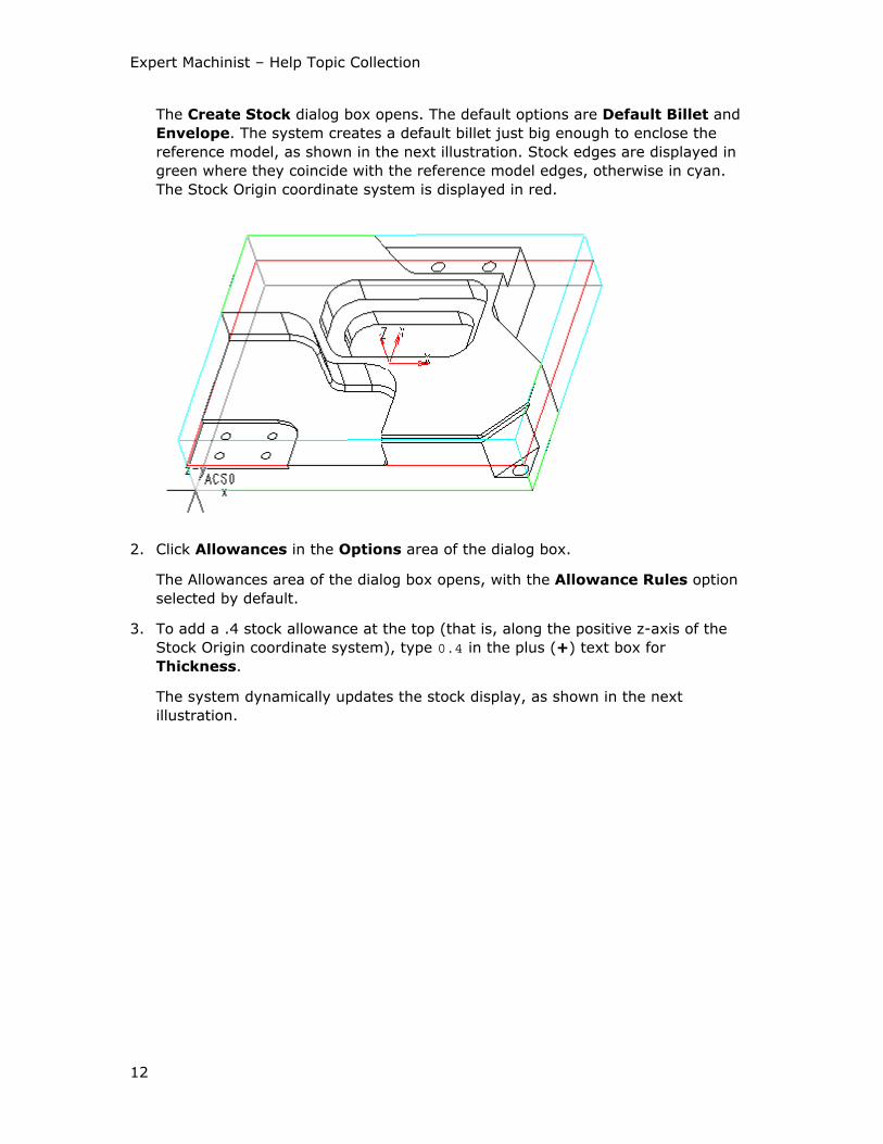
The Create Stock dialog box opens. The default options are Default Billet and
Envelope. The system creates a default billet just big enough to enclose the
reference model, as shown in the next illustration. Stock edges are displayed in
green where they coincide with the reference model edges, otherwise in cyan.
The Stock Origin coordinate system is displayed in red.
2. Click Allowances in the Options area of the dialog box.
The Allowances area of the dialog box opens, with the Allowance Rules option
selected by default.
3. To add a .4 stock allowance at the top (that is, along the positive z-axis of the
Stock Origin coordinate system), type 0.4 in the plus (+) text box for
Thickness.
The system dynamically updates the stock display, as shown in the next
illustration.
Using Additional Modules
13
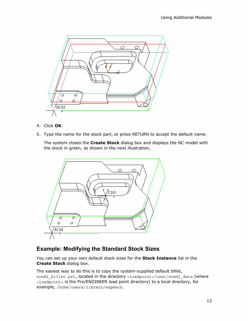
4. Click OK.
5. Type the name for the stock part, or press RETURN to accept the default name.
The system closes the Create Stock dialog box and displays the NC model with
the stock in green, as shown in the next illustration.
Example: Modifying the Standard Stock Sizes
You can set up your own default stock sizes for the Stock Instance list in the
Create Stock dialog box.
The easiest way to do this is to copy the system-supplied default billet,
ncmdl_billet.prt, located in the directory <loadpoint>/text/ncmdl_data (where
<loadpoint> is the Pro/ENGINEER load point directory) to a local directory, for
example, /home/users/library/expmach.
Expert Machinist – Help Topic Collection
14
Retrieve the ncmdl_billet.prt from the local directory and modify its family table
to reflect the standard stock sizes that you need.
Set the configuration option:
ncmdl_billet_stock_part_path /home/users/library/expmach/ncmdl_billet.prt
To set the default stock sizes for bar-shaped stock, repeat this procedure with the
system-supplied default bar, ncmdl_bar.prt, and use the configuration option
ncmdl_bar_stock_part_path.
To Modify Stock Allowances
Stock allowances are added along the Stock Origin coordinate system axes. For
Length, Width, and Height, typing a value in the plus (+) textbox specifies the
stock allowance on the positive side of the corresponding axis, while typing a value
in the minus (-) textbox specifies the stock allowance on the negative side of the
same axis. There is only one textbox for Diameter stock allowance (for a Default
Bar stock).
1. Click the Allowances field in the Options area of the Create Stock dialog box.
The Allowances area of the dialog box expands. It contains the following
options:
o Allowance Rules—Define the minimum stock allowances with respect to
the reference part envelope. This option is primarily used with Envelope
stocks.
o Current Allowance—Show the current stock allowance values. For Custom
stocks, you can redistribute the current extra material among the stock
faces, that is, shift the stock with respect to the reference model. For
Envelope stocks, the current stock allowances are listed for information
purposes only; you cannot change them. For Default Bar stocks, the
Diameter stock allowance is also listed for information purposes only.
2. For Envelope stocks, select Allowance Rules and type the desired stock
allowance values in the plus (+) and minus (-) textboxes for Length, Width,
and Thickness, and in the Diameter textbox.
As you change a value, the system adds the stock allowance along the
appropriate axis of the Stock Origin coordinate system (x-axis for Length, y-axis
for Width, and z-axis for Thickness) and updates the stock display.
3. For Custom stocks, you can also specify Allowance Rules, if desired. This does
not directly affect the stock size. However, if you define Allowance Rules for a
Custom stock and later modify the Stock Size, the system will not let you
decrease the stock dimensions to violate these rules. For example, if your
reference model length is 10.000 inches, and you specified both a plus (+) and
minus (-) stock allowance for Length as 0.500, the system will not let you
decrease the Length value in the Stock Size area of the dialog box to less than
11.000 inches.
Using Additional Modules
15
4. For Custom stocks, you can change current stock allowances to shift the stock
with respect to the reference model. To do this, select Current Allowance and
type the desired value in one of the textboxes, for example, in the plus (+)
textbox for Length.
The system updates the value in the second textbox and shifts the stock (in this
example, along the x-axis of the Stock Origin coordinate system).
To Modify Stock Outline
You can change the position of the stock with respect to the reference model by
rotating the axes of the Stock Origin coordinate system or aligning them to the
reference part geometry.
1. Click the Modify Outline field in the Options area of the Create Stock dialog
box.
The Modify Outline area of the dialog box expands. It contains the following
options:
o Rotate—Rotate stock about the axes of the Stock Origin coordinate
system.
o Align Axis—Align the axes of the Stock Origin coordinate system to the
entities of the reference model geometry. If the Move to axis checkbox is
selected, the Stock Origin coordinate system will be moved to the selected
reference, otherwise it is rotated about its origin to align the direction of the
coordinate system axis with the selected reference.
2. Click Rotate, select an axis option (X, Y or Z), and move the slider below to the
desired angle. The current slider position is shown in the Value text box. You can
also type the desired rotation angle in the Value text box.
The system rotates the stock and displays the Stock Origin coordinate system in
the new orientation.
3. Click Align Axis, select an axis option (X, Y or Z), select or clear the Move to
axis checkbox, as necessary, then click the button with the Select arrow.
The GEN SEL DIR menu opens with the following commands:
o Plane—Use a plane normal to specify direction.
o Crv/Edg/Axis—Use a straight edge or curve segment or a datum axis to
specify direction.
o Csys—Use a coordinate system axis to specify direction.
4. Click the command you want on the GEN SEL DIR menu and select an entity on
the reference model. Then use the Flip and Okay commands to reverse or
accept the direction (shown by a red arrow).
The system moves the stock and displays the Stock Origin coordinate system in
the new position.

Expert Machinist – Help Topic Collection
16
Operations
To Create an Operation
You have to create an operation before you can start defining machining features.
When creating the operation, the required elements are the machine tool name and
the Program Zero coordinate system.
1. Click NC Setup > Operation.
The Operation Setup dialog box opens. It contains the default settings for the
operation name and output parameters. To change the default name, type the
new name in the Operation Name text box.
Note: If you already have defined some operations for the current machining
process, click the New icon at the top of the dialog box to start creating a new
operation.
2. Select or create a machine tool. If you have set up some machine tools prior to
creating the operation, their names appear in the NC Machine drop-down list. To
create a machine tool, click next to the NC Machine drop-down list.
3. Define the Program Zero. Click next to the Machine Zero text box and
select or create a coordinate system. Once the Program Zero is defined, the
name of the coordinate system appears in the Machine Zero text box, and
clicking the Show button next to it will highlight the coordinate system on the
screen.
4. Use any of the other, optional, elements of operation setup, if needed. You can:
o Use the icons in the Fixture Setup section to set up the fixtures. If you do
not do anything at this point, the system automatically creates an empty
fixture setup with a default name. You can modify this setup or create
additional setups later.
o Specify the rotary clearance for 4-axis machines.
o Select a name of the stock material type and condition, if you have a preset
Material directory structure.
o On the From/Home tab, specify datum points to serve as FROM and HOME
locations.
o On the Output tab, change the output parameters or type the operation
comments, to be output using PPRINT.
5. Click OK to finalize creating the operation and close the dialog box.
6. If you want to immediately create another operation, click Apply, and then click
the New icon at the top of the Operation Setup dialog box.
The Operation Setup Dialog Box
The Operation Setup dialog box contains the following elements:
Using Additional Modules
17
• Operation Name—The operation name identifies the operation within the
manufacturing process. The default operation names have the format OP010,
OP020, where the number gets automatically incremented by the system. You
can type any name.
• NC Machine—The name of the machine tool used to perform the operation. If
you have set up some machine tools prior to creating the operation, their names
appear in the NC Machine drop-down list. To create or redefine a machine tool,
click next to the NC Machine drop-down list.
• Fixture Setup—This section contains the icons for creating, modifying, and
deleting fixture setups. The drop-down list contains the names of all the fixture
setups defined for the operation, with the name of the currently active setup
displayed in the list box.
In the lower portion of the Operation Setup dialog box there are three tabs:
General, From/Home, and Output. They contain the following elements:
The General tab
• Defaults—Opens the Expert Machinist - Defaults dialog box, which lets you
specify the default template to be used for machining of every type of feature.
You can launch the Template Manager directly from the Expert Machinist -
Defaults dialog box, to create the templates you need. As you save new
templates to disk, you can read their names into the appropriate lists in the
Expert Machinist - Defaults dialog box by clicking the Refresh icon at the top
of the dialog box. Other icons at the top of the dialog box let you save the default
settings to a file (with the .tda extension), which can be later retrieved into a
different operation; read a previously saved file into the current operation; and
reset all the default template types to Unspecified.
Notes:
o The name of a .tda file can not be longer than 31 characters and must all
be lowercase.
o Expert Machinist uses the concept of a modal tool; that is, once you specify
a cutting tool, all subsequent machining features will use this tool until you
explicitly change it. (Look in the Index for details on other modal settings in
Expert Machinist.) Therefore, when you use a Default template to create a
Tool Path, the system does not copy the tool information from the
template; instead, it uses the modal tool.
• Machine Zero—Select or create a coordinate system to be used as the Program
Zero for NC output and for other machining references.
• Use Rotary Clearance—This option is available for 4-axis machines only. It
allows you to define a safe z-level retract height for cutting tools, to ensure
safety of table rotations. The Rotation Clearance value specifies the minimum
distance by which the NC Model and fixture components will be cleared during
table rotations. The default value is 2" (in English units) or 50 mm (in metric
units). You can type any positive value. In addition, you can specify a Safe
Rotary Point for tools that are too long to be retracted to the Rotation Clearance
Expert Machinist – Help Topic Collection
18
level. Type the X, Y, and Z coordinate values in the Safe Rotary Point text
boxes. In order for a tool to use the Safe Rotary Point instead of Rotation
Clearance, you have to mark it as "long" in the Tool Manager, by selecting the
Long Tool checkbox on the Settings tabbed page of the Tool Setup dialog box.
• Stock Material—Select a name of the stock material.
Note: You have to set up the material directory structure up front; otherwise,
the only option available in the Stock Material drop-down list is Unspecified.
The From/Home tab
• FROM Point—Create or select a datum point to serve as the FROM location.
Once set, the name of the datum point appears in the text box. Clicking
highlights the datum point on the screen. Clicking cancels the FROM
setting.
• HOME Point—Create or select a datum point to serve as the HOME location.
Once set, the name of the datum point appears in the text box. Clicking
highlights the datum point on the screen. Clicking cancels the HOME
setting.
The Output tab
• Output NCL File—The default name for the operation cutter location (CL) data
file. You can type any name. Clicking Use Default sets it back to the system
default.
• PARTNO—The part name, output with the PARTNO command, as well as using
PPRINT. You can type any name. Clicking Use Default sets it back to the system
default.
• Startup File—Type the name of the file you want to be included at the very
beginning of the operation CL file (after the PARTNO, MACHIN, and UNITS
commands). The file must be located in your current working directory and have
the extension .ncl.
• Shutdown File— Type the name of the file you want to be included at the very
end of the operation CL file. The file must be located in your current working
directory and have the extension .ncl.
• Comments—Type the operation comments in the text box below. These
comments can be output using PPRINT.
To Define Program Zero
To define Program Zero, you have to create or select a coordinate system, which will
define the orientation of the stock on the machine and act as the origin (0, 0, 0) for
CL data generation. The Program Zero coordinate system can belong to the
reference model, stock, or the NC Model assembly; it can be created in Part or
Assembly mode, outside of Expert Machinist, or directly at the time of defining
Program Zero.
Using Additional Modules
19
Program Zero for an operation or a machining feature is specified in a similar way, as
described in the following procedure.
1. To define Program Zero at the operation level, click the Select arrow next to
Machine Zero in the Operation Setup dialog box.
To define Program Zero at the feature level, click the Select arrow next to
Define Program Zero in the appropriate machining feature dialog box (for
example, Pocket Feature).
2. The MACH CSYS or the SEQ CSYS menu, respectively, appears with the following
commands:
o Create—Select which model the coordinate system will belong to, then
create the coordinate system.
o Select—Select an existing coordinate system, either by selecting on the
screen or by using the Sel By Menu command.
o Use Prev—Lets you select a coordinate system used for an earlier
operation or machining feature.
3. Click Done.
If you click Show, the operation Program Zero is highlighted in red; if you
specify a different Program Zero at the feature level, it is highlighted in magenta.
Program Zero Usage
You can define Program Zero at the operation level or at the machining feature level:
• Operation Program Zero—Specified at the time of operation setup; acts as the
default origin for the NC output. All machining features created within a certain
operation will use the same operation Program Zero.
• Feature Program Zero—Specified at the time of defining a feature; defines the
orientation of the stock on the machine and affects the tool path creation, such
as retract and cut feed direction. The feature Program Zero coordinate system
must be oriented in a certain way, as described in the following section.
If you do not explicitly define a feature Program Zero, the system will implicitly use
the operation Program Zero to define the orientation of the stock on the machine and
generate tool path. However, the Program Zero setting is modal, that is, once you
specify a separate Program Zero for a feature, it will stay for all subsequent features
until you change it.
If the operation and feature Program Zeroes are different, then, upon creating the
tool path for a feature, all the cutter location (CL) data will be transformed and
output in the coordinates of the operation Program Zero coordinate system. If the z-
axes of the two coordinate systems are not parallel, the tool orientation vector (i,j,k)
or table rotation will be provided. This functionality allows you to postprocess 3-axis
operations to be performed on the 5-axis machines.
Note: You can specify that the linear and rotational transitions between the two
Program Zero coordinate systems be output in the CL file, instead of transforming all
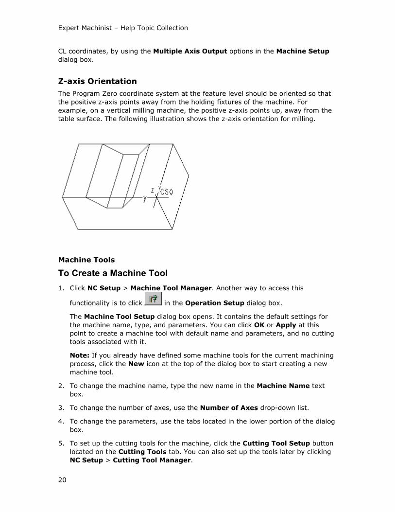
Expert Machinist – Help Topic Collection
20
CL coordinates, by using the Multiple Axis Output options in the Machine Setup
dialog box.
Z-axis Orientation
The Program Zero coordinate system at the feature level should be oriented so that
the positive z-axis points away from the holding fixtures of the machine. For
example, on a vertical milling machine, the positive z-axis points up, away from the
table surface. The following illustration shows the z-axis orientation for milling.
Machine Tools
To Create a Machine Tool
1. Click NC Setup > Machine Tool Manager. Another way to access this
functionality is to click in the Operation Setup dialog box.
The Machine Tool Setup dialog box opens. It contains the default settings for
the machine name, type, and parameters. You can click OK or Apply at this
point to create a machine tool with default name and parameters, and no cutting
tools associated with it.
Note: If you already have defined some machine tools for the current machining
process, click the New icon at the top of the dialog box to start creating a new
machine tool.
2. To change the machine name, type the new name in the Machine Name text
box.
3. To change the number of axes, use the Number of Axes drop-down list.
4. To change the parameters, use the tabs located in the lower portion of the dialog
box.
5. To set up the cutting tools for the machine, click the Cutting Tool Setup button
located on the Cutting Tools tab. You can also set up the tools later by clicking
NC Setup > Cutting Tool Manager.
Using Additional Modules
21
6. Click OK to finalize the machine tool creation and close the dialog box.
7. If you want to immediately create another machine tool, click Apply, and then
click the New or the Open icon at the top of the Machine Tool Setup dialog
box.
You can save the current machine tool, along with its parameters, by clicking the
Save icon at the top of the Machine Tool Setup dialog box. You can then use
the Open icon at the top of the Machine Tool Setup dialog box to create a new
machine tool with the same parameters, whether in this or in another NC
process.
Machine Tool Settings
A machine tool is identified by the following elements:
• Machine Name—The machine name identifies the machine tool within the
manufacturing process. The default machine names have the format MACH01,
MACH02, where the number gets automatically incremented by the system. You
can type any name.
When you save the machine tool data on disk, the system uses the Machine
Name as a filename (with the .cel extension).
• Machine Type—The machine type is Mill.
• Number of Axes—Can be 3 Axis (default), 4 Axis, or 5 Axis.
• CNC Control—The controller name (optional).
• Location—The location of the machine tool (optional).
The tabs on the Machine Tool Setup dialog box enable you to specify the following
parameters of a machine tool.
The Output tab
Post Processor Options
• PP Name—The name of the default postprocessor associated with the machine.
Type the name in the text box. The Reset button lets you change the name back
to the system default.
• ID—The postprocessor ID.
PPRINT—Opens the PPRINT menu to let you set up your PPRINT options.
CL Command Output Options
• FROM—Specifies how the FROM statement will be output to an operation CL data
file:
o Do Not Output (default)—No FROM statements are output. If a From point
is specified, its location is output as a GOTO statement at positioning feed.
o Only At Start—A FROM statement is output at the beginning of the file. It
corresponds to the location of the From point, if specified, or to the first
Expert Machinist – Help Topic Collection
22
location on the tool path for the first machining feature. All other tool paths
are added to the operation without a FROM statement.
o At Every Tool Path—FROM statements are output at the beginning of each
tool path for a machining feature. For the first tool path, this FROM
statement corresponds to the location of the operation From point, if
specified, or to the first location on the tool path for this machining feature.
• LOADTL—Controls the output of the LOADTL command in the operation CL data
file:
o Modal (default)—The LOADTL command is output at the beginning of CL
data for a feature tool path only if a tool change is needed.
o Not Modal—Outputs the LOADTL statement at the beginning of each
feature tool path, regardless of whether the tool is the same or changed.
• COOLNT/OFF—Controls the output of the COOLNT/OFF statement.
o Output (default)—The COOLNT/OFF statement is output at the end of each
feature tool path.
o Do Not Output—COOLNT/OFF is output only once, at the end of the file.
• SPINDL/OFF—Controls the output of the SPINDL /OFF statement.
o Output (default)—The SPINDL /OFF statement is output at the end of each
feature tool path.
o Do Not Output—SPINDL /OFF is output only once, at the end of the file.
Multiple Axis Output Options
These options become accessible when you set Number of Axes to 4 Axis.
• Use Rotate Output—If this option is not selected (default), all CL data is
transformed and output in the coordinates of the Program Zero coordinate
system. When you select this option, the system outputs the applicable TRANS
and ROTABL commands to specify linear and rotational transformations. Only
select this option when indexing to a new table position is desired.
• Rotation Output Mode—Available only when Use Rotate Output is selected.
Controls output of ROTABL statements. The values are: Incremental (default)
and Absolute. In Absolute mode, zero position is defined by the Program Zero.
• Rotation Direction—Available only when Use Rotate Output is selected.
Allows you to specify that rotation is performed in a particular direction (this may
occur when there is an obstruction in one rotation direction but not another). The
values are:
o Shortest (default)—Make the shortest possible move to the new position.
o CLW—Always rotate in the clockwise direction.
o CCLW—Always rotate in the counterclockwise direction.
• Rotation Axis—Specify the rotation axis: A-Axis or B-Axis (default).
Using Additional Modules
23
Cutter Compensation
When you expand this field, the Output cutter position options become available:
• Tool Center—Cutter location (CL) data is output with respect to the tool center.
• Tool Edge—Cutter location (CL) data is output with respect to the cutting edge
of the tool. If you select this option, type the desired value in the Safe Radius
text box. This value represents the smallest concave corner radius that can be
safely machined, and must be slightly bigger than the radius (Cutter Diameter/2)
of the biggest tool on the machine. The Adjust Corner drop-down list gives you
a choice of corner condition options for convex corners:
o Straight—When passing a convex corner, the tool path consists of two
straight segments extended until they intersect.
o Fillet—When passing a convex corner, the tool path consists of two straight
segments connected with an arc.
o Automatic—The system adds a fillet corner condition at all the convex
corners on the outside contour of the part, and a loop corner condition at all
the convex corners on the inside contour of the part.
The Spindle tab
• Maximum Speed—Maximum allowable spindle speed for the machine tool
(optional). Type the maximum speed value in RPM (revolutions per minute).
• Horsepower—Spindle horsepower (optional).
The Feed tab
• Feed Units—Select the rapid feed rate units from the Rapid Traverse drop-
down list. The values are:
o IPM (default)—inches per minute
o MMPM—millimeters per minute
• Feed Limits—Type the value of the feed rate used for rapid traverse in the
Rapid Feed Rate text box (optional).
The Cutting Tools tab
• Tool Change Time—Time needed for changing a tool, in seconds (optional).
Type the value in the text box, or use the UP and DOWN arrows next to the text
box to increase or decrease the value, respectively.
• The Cutting Tool Setup button opens the Tool Setup dialog box to let you set
up the cutting tools associated with the machine tool.
The Travel tab
Lets you specify the travel limits for the machine tool: X-Axis Travel, Y-Axis
Travel, and Z-Axis Travel. Specifying these values is optional. Values for the travel
limits along the axes should be the actual dimensions that indicate the extent of the
machine tool workspace relative to the Program Zero coordinate system. For
example, if a machine tool is 60 inches wide, and the origin of the Program Zero
Expert Machinist – Help Topic Collection
24
coordinate system is located halfway between the ends, specify the travel limits for
X-Axis Travel as follows: type -30 in the left text box and 30 in the text box on the
right.
If you display or otherwise output the CL data for a machining feature that exceeds
the limitations of the machine tool where it is defined, the Information Window will
appear, listing the values of the limits that have been exceeded and their
corresponding actual values.
The Comments tab
Type the comments associated with the machine tool in the text box (optional).
To Set Up a PPRINT Table
1. On the Output tab of the Machine Tool Setup dialog box, click PPRINT.
The PPRINT menu opens with the following options:
o Create—Create a new PPRINT table.
o Modify—Modify the current PPRINT table.
o Retrieve—Retrieve an existing PPRINT table from the current working
directory.
o Save—Save the current PPRINT table for later use. You will be prompted
for the name of the file. The file will have an extension .ppr and will be
stored in the current working directory.
o Show—Show the current PPRINT settings.
2. If the table has not been set up, the Modify option will be grayed out. Choose
Create. If you have previously set up a PPRINT table, you can either change your
former settings using the Modify option, or start with a clean table using Create.
The system displays the Activate PPRINT dialog box. It contains all the items
that can be output through PPRINT. Whether an item will be output or not is
determined by the flag value. The default flag value for all items is No. Change it
to Yes if you want the item to be output.
3. To change the flag value, highlight the item or items in the PPRINT table by
clicking on them once, then click on the appropriate action button (Yes or No),
located in the lower-left portion of the dialog box. To unselect an item, click on it
once more. You can also use the Select All and Unselect All icons located in the
lower-right portion of the dialog box.
4. To supply comments for an item, highlight it and type the comment in the
Comments text box. When you highlight an item with an existing comment, the
comment is displayed in the Comments text box. While editing a comment, you
can revert to the previous value by clicking the drop-down arrow next to the
Comments text box.
5. Click OK to finish setting up the PPRINT table.
Using Additional Modules
25
The PPRINT Table
To output some model information to the CL files, you have to set up a PPRINT table
for this model. This table contains all the items that can be output through PPRINT.
Whether an item will be output or not is determined by the flag value. The default
flag value for all items is No. Change it to Yes if you want the item to be output. You
can add an optional comment to be output along with the item.
Note: Comments are limited to 69 characters or less.
Whenever you output CL data to file, the system will check the PPRINT table. If any
flag is set to Yes and the appropriate information is available, the corresponding
PPRINT command will be output to the CL file.
The following items are output once per CL file:
• PART_NAME
• DATE_TIME
• SCALE
• TRANSLATE
• ROTATE
The following items are output once per operation:
• OPERATION_NAME
• OPERATION_COMMENTS
• LAYER_NAME
• UDF_NAME
• TOOL_TABLE
• ONLY_OUTPUT_USED_TOOLS
The following items are output once per feature:
• NC_SEQUENCE_NAME — The machining feature name.
• NC_SEQUENCE_COMMENTS — Comments associated with the machining feature.
• FEATURE_ID
• SEQUENCE_TYPE — The machining feature type.
• CUTCOM_REGISTER
• SPINDLE_SPEED
• CUT_FEEDRATE_&_UNITS
• ARC_FEEDRATE_&_UNITS
• FREE_FEEDRATE_&_UNITS
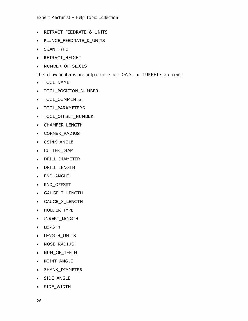
Expert Machinist – Help Topic Collection
26
• RETRACT_FEEDRATE_&_UNITS
• PLUNGE_FEEDRATE_&_UNITS
• SCAN_TYPE
• RETRACT_HEIGHT
• NUMBER_OF_SLICES
The following items are output once per LOADTL or TURRET statement:
• TOOL_NAME
• TOOL_POSITION_NUMBER
• TOOL_COMMENTS
• TOOL_PARAMETERS
• TOOL_OFFSET_NUMBER
• CHAMFER_LENGTH
• CORNER_RADIUS
• CSINK_ANGLE
• CUTTER_DIAM
• DRILL_DIAMETER
• DRILL_LENGTH
• END_ANGLE
• END_OFFSET
• GAUGE_Z_LENGTH
• GAUGE_X_LENGTH
• HOLDER_TYPE
• INSERT_LENGTH
• LENGTH
• LENGTH_UNITS
• NOSE_RADIUS
• NUM_OF_TEETH
• POINT_ANGLE
• SHANK_DIAMETER
• SIDE_ANGLE
• SIDE_WIDTH
Using Additional Modules
27
• TOOL_MATERIAL
• TOOL_ORIENTATION
• TOOL_TYPE
Fixtures
About Fixtures
Fixtures are parts or assemblies that help orient and hold the stock during a
manufacturing operation. You can create and save fixture components in Part or
Assembly mode, and then assemble them to the NC Model in Expert Machinist, or
create the components directly in Expert Machinist by referencing geometry of the
NC Model.
To use fixtures in a manufacturing process, you must first define the fixture setups
for the manufacturing model. Each fixture setup has a name and contains
information about the fixtures (components) that are to be present in the model
when the setup is active. You can define fixture setups at the time of setting up an
operation or at any time between creating features and tool paths.
Fixture setups belong to operations. When you create an operation, the system
automatically creates an empty fixture setup for this operation. This first fixture
setup is inserted in the Model Tree above the operation, to let you use the fixture
geometry for defining the operation Program Zero. You can modify this setup by
adding components to it. You can also create other fixture setups for the same
operation (these setups are placed in the Model Tree under the operation). Note that
although an operation can have multiple fixture setups associated with it, only one
fixture setup can be active at a time. When you create a machining feature, it is
automatically inserted in the Model Tree under the currently active fixture setup. The
system considers fixture components when generating the machining feature
geometry and creates the appropriate Hard Walls, if necessary.
When you create a new operation, it does not inherit the fixture setups from the
previous operation. If you want to use fixture setups from a previous operation, you
can copy them by using the Copy icon at the top of the Fixture Setup dialog box.
To Create a Fixture Setup
1. Click NC Setup > Fixture. Another way to access this functionality is to click
in the Fixture Setup section of the Operation Setup dialog box.
The Fixture Setup dialog box opens. It contains the default name for the fixture
setup (for example, FSETP1). You can change it by typing a different name.
2. Create or assemble components that you want to include in the fixture setup. You
can also copy a previously defined fixture setup by using the Copy icon at the
top of the Fixture Setup dialog box.
When you add fixture setup components, you may find that they clutter up the
screen and make it difficult to select surfaces for feature creation. In this case,
you can blank the fixture components, that is, erase them from the display but

Expert Machinist – Help Topic Collection
28
keep them in the fixture setup; the blanked fixture components will still be used
as references for creating machining features. When you blank a component, its
visibility status in the Components list is changed to Invisible.
3. Click OK to finalize the fixture setup creation and close the dialog box. This setup
becomes active (that is, it will be used for the newly created machining features).
The Fixture Setup Dialog Box
The top portion of the Fixture Setup dialog box contains the following icon:
—Copy a previously defined fixture setup. This brings in all the components
from the setup being copied. You can then remove or redefine placement of some of
the components, or add extra components, by using the action buttons in the lower
portion of the Fixture Setup dialog box.
The Fixture Setup Name box contains the name of the fixture setup. You can type
any name.
The middle portion of the Fixture Setup dialog box contains two tabbed pages:
Components and Comments. The Components tabbed page lists all the
components currently included in the fixture setup, along with their visibility status.
You can type information about the fixture setup in the text box on the Comments
tabbed page.
Below the tabbed pages are the following action buttons:
—Create a new fixture component. The user interface is the same as creating a
new part in Assembly mode. After you create the component, its name appears in
the list on the Components tabbed page.
—Redefine placement of a fixture component. Select the name of the
component to be reassembled in the list box on the Components tabbed page, then
click this button. Specify the new assembly constraints for the component.
—Assemble a new fixture component. The user interface is the same as
assembling a new component in Assembly mode. After you assemble the component,
its name appears in the list on the Components tabbed page.
—Remove a fixture component. Select the names of the components to be
removed in the list box on the Components tabbed page, then click this button.
—Make a fixture component visible. Select the names of the previously blanked
components in the list box on the Components tabbed page, then click this button.
The components are displayed on the screen, and their status in the Components
list is changed to Visible.
—Make a fixture component invisible. Select the names of the components to
be blanked in the list box on the Components tabbed page, then click this button.
The components are erased from the screen, and their status in the Components
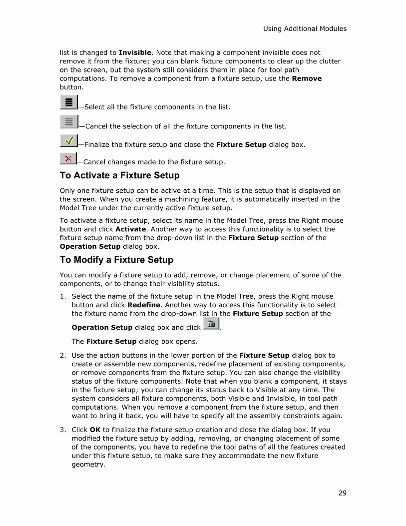
Using Additional Modules
29
list is changed to Invisible. Note that making a component invisible does not
remove it from the fixture; you can blank fixture components to clear up the clutter
on the screen, but the system still considers them in place for tool path
computations. To remove a component from a fixture setup, use the Remove
button.
—Select all the fixture components in the list.
—Cancel the selection of all the fixture components in the list.
—Finalize the fixture setup and close the Fixture Setup dialog box.
—Cancel changes made to the fixture setup.
To Activate a Fixture Setup
Only one fixture setup can be active at a time. This is the setup that is displayed on
the screen. When you create a machining feature, it is automatically inserted in the
Model Tree under the currently active fixture setup.
To activate a fixture setup, select its name in the Model Tree, press the Right mouse
button and click Activate. Another way to access this functionality is to select the
fixture setup name from the drop-down list in the Fixture Setup section of the
Operation Setup dialog box.
To Modify a Fixture Setup
You can modify a fixture setup to add, remove, or change placement of some of the
components, or to change their visibility status.
1. Select the name of the fixture setup in the Model Tree, press the Right mouse
button and click Redefine. Another way to access this functionality is to select
the fixture name from the drop-down list in the Fixture Setup section of the
Operation Setup dialog box and click .
The Fixture Setup dialog box opens.
2. Use the action buttons in the lower portion of the Fixture Setup dialog box to
create or assemble new components, redefine placement of existing components,
or remove components from the fixture setup. You can also change the visibility
status of the fixture components. Note that when you blank a component, it stays
in the fixture setup; you can change its status back to Visible at any time. The
system considers all fixture components, both Visible and Invisible, in tool path
computations. When you remove a component from the fixture setup, and then
want to bring it back, you will have to specify all the assembly constraints again.
3. Click OK to finalize the fixture setup creation and close the dialog box. If you
modified the fixture setup by adding, removing, or changing placement of some
of the components, you have to redefine the tool paths of all the features created
under this fixture setup, to make sure they accommodate the new fixture
geometry.
Expert Machinist – Help Topic Collection
30
To Delete a Fixture Setup
Use either of the following ways to delete a fixture setup:
• Select the name of the fixture setup in the Model Tree, press the Right mouse
button and click Delete.
• Select the fixture name from the drop-down list in the Fixture Setup section of
the Operation Setup dialog box and click .
Note that if you delete a fixture setup the system prompts you to delete or suspend
all the machining features and tool paths that have been created under this fixture
setup. If you want to keep the features but no longer need the fixtures to machine
them, you can modify the setup and remove all the components from it, rather than
delete the setup itself. You might have to redefine the tool paths of the features
created under this fixture setup, to make sure they no longer account for the fixture
geometry.
Tips: Using Fixture Setups
The following are some of the scenarios you may encounter when using the Fixture
Setup functionality in Expert Machinist:
• If you use fixtures for the first feature or features in an operation, and no longer
need them to machine subsequent features, do not delete or modify the original
fixture setup. Create a new, empty, fixture setup and make it active, then create
the subsequent machining features.
• Similarly, if you need to change your fixture configuration for machining
subsequent features in an operation, leave the original fixture setup intact and
create a new fixture setup for subsequent features.
• If two fixture setups are just slightly different, use the Copy functionality. For
example, you have a fixture setup with jigs and clamps for machining a Profile
and a Step feature; then you need to remove a clamp to machine a boss top.
Create a new fixture setup and use the Copy icon at the top of the Fixture
Setup dialog box to bring in all the components from the original setup. Select
the name of the clamp in the Components list and click . Make sure the
new fixture setup is active, then create the Boss Top feature.
• If you delete a fixture setup the system prompts you to delete or suspend all the
machining features and tool paths that have been created under this fixture
setup. If you want to keep the features but no longer need the fixtures to
machine them, you can modify the setup and remove all the components from it,
rather than delete the setup itself.
Cutting Tools
About Setting Up Tools
You can set up the cutting tools in advance, as part of the NC setup, and then select
the appropriate tool when machining a feature, or create tools on the fly at the time

Using Additional Modules
31
of machining. Whenever you access the Cutting Tool Manager, the system displays
the Tool Setup dialog box, which enables you to create, modify, and delete tools, as
well as to review the tools already defined for the current machine.
To Set Up Cutting Tools
To access the Cutting Tool Manager, do one of the following:
• On the top menu bar, click NC Setup > Cutting Tool Manager (this option
becomes available after you set up an operation and a machine tool).
• On the Cutting Tools tab of the Machine Tool Setup dialog box, click Cutting
Tool Setup.
• At the time of machining a feature, click next to the Cutting Tool text box
in the feature-specific machining dialog box (for example, Pocket Milling).
Either of these actions opens the Tool Setup dialog box, with its name preceded by
the name of the current machine tool. From the Tool Setup dialog box, you can
create, modify, and delete tools, as well as review the tools already defined for the
current machine.
The Tool Setup Dialog Box
The upper portion of the Tool Setup dialog box contains the Tool Table for the
current machine. The Tool Table defines the correspondence between a descriptive
tool name (Name) and its location on the machine, that is, its pocket number
(Number). You can optionally supply a value for the gauge length register (Offset)
and comments output for the tool (Comments). Each machine tool has its own Tool
Table.
When you select a Tool Table entry in the upper portion of the Tool Setup dialog
box, the system updates the middle and lower portions to display this tool’s
parameters and section sketch.
The middle portion of the Tool Setup dialog box contains the Tool Preview window,
with the current tool section sketch, and the text boxes for defining the following tool
elements:
• Name—A descriptive tool name (for example, BALL125), which uniquely
identifies the tool with a certain set of parameter values. The tool name is used
throughout Expert Machinist to identify the tool. You can store the tool’s
parameters in a text file and then retrieve it to use in a different manufacturing
process. The tool Name serves as the name for this parameter file, therefore, all
the operating system’s restrictions for file names apply to Name (for example, it
cannot contain spaces or periods). The name must be less than thirty-two
alphanumeric characters long.
Note: The tool name can not contain hyphens (-). Underscores (_), however, can
be used.
• Type—Select one of the predefined tool types available in Expert Machinist. Tool
types correspond to the type of the machine tool and of the machining feature
(for example, you will need a milling tool to mill a Pocket; to machine a Hole

Expert Machinist – Help Topic Collection
32
Group feature, you can use both milling and drilling tools). The tool type, in turn,
defines the tool’s cross section and, therefore, the set of parameters you have to
specify for the tool.
• Material—Specify the material that the tool is made of.
• Units—Length units of the tool. The default length units of a tool are those of the
stock. If you change the Units, this will affect the actual tool dimensions.
The lower portion of the Tool Setup dialog box contains four tabbed pages:
Geometry, Settings, Speeds & Feeds, and BOM.
The Geometry tabbed page contains the text boxes for defining the Geometry
parameters, that is, parameters that specify all the dimensions of the tool. These
dimension values are used in calculating the tool path and material removed, and
should accurately reflect the actual tool dimensions and length units. Some of the
parameters are required for defining the tool's cross section, others are optional. The
actual parameter names in this category depend on the tool Type.
The Settings tabbed page contains the text boxes for defining some of the tool table
elements and various optional parameters that define tool properties other than
geometry:
• Tool Number—Corresponds to the Number field of the Tool Table, which
defines the tool's pocket number.
• Offset Number—Corresponds to the Offset field of the Tool Table, which
supplies a value for the gauge length register.
• Tool gauge lengths (Gauge X Length and Gauge Z Length)—Optional
parameters used to create length qualifiers in the LOADTL or TURRET statements.
• Long Tool—Select this checkbox if the tool is too long to retract to the Rotation
Clearance level during 4-axis machining. If you mark the tool as long, the tip of
the tool will move to the Safe Rotary Point (specified in the Operation Setup
dialog box) during table rotations.
• Comments—A text string that will be stored along with the tool parameters and
output with the tool table using PPRINT. If you want the tool table to show this
comment, click Edit > Table Comments in the top menu bar of the Tool Setup
dialog box, and select the Use TOOL_COMMENT parameter option. If you want
the tool table to show a comment different than the tool Comments parameter
string, click Edit > Table Comments, select New Comment, and type in a new
comment string.
The Speeds & Feeds tabbed page lets you supply cutting data (feed, speed, axial
and radial depths) for roughing and finishing with this tool, based on the stock
material type and condition.
The BOM tabbed page provides information about the Bill of Materials for the tool.
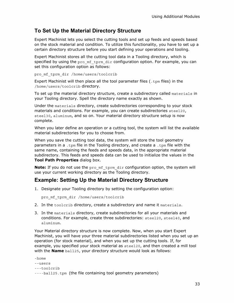
Using Additional Modules
33
To Set Up the Material Directory Structure
Expert Machinist lets you select the cutting tools and set up feeds and speeds based
on the stock material and condition. To utilize this functionality, you have to set up a
certain directory structure before you start defining your operations and tooling.
Expert Machinist stores all the cutting tool data in a Tooling directory, which is
specified by using the pro_mf_tprm_dir configuration option. For example, you can
set this configuration option as follows:
pro_mf_tprm_dir /home/users/toolcrib
Expert Machinist will then place all the tool parameter files (.tpm files) in the
/home/users/toolcrib directory.
To set up the material directory structure, create a subdirectory called materials in
your Tooling directory. Spell the directory name exactly as shown.
Under the materials directory, create subdirectories corresponding to your stock
materials and conditions. For example, you can create subdirectories steel20,
steel30, aluminum, and so on. Your material directory structure setup is now
complete.
When you later define an operation or a cutting tool, the system will list the available
material subdirectories for you to choose from.
When you save the cutting tool data, the system will store the tool geometry
parameters in a .tpm file in the Tooling directory, and create a .tpm file with the
same name, containing the feeds and speeds data, in the appropriate material
subdirectory. This feeds and speeds data can be used to initialize the values in the
Tool Path Properties dialog box.
Note: If you do not use the pro_mf_tprm_dir configuration option, the system will
use your current working directory as the Tooling directory.
Example: Setting Up the Material Directory Structure
1. Designate your Tooling directory by setting the configuration option:
pro_mf_tprm_dir /home/users/toolcrib
2. In the toolcrib directory, create a subdirectory and name it materials.
3. In the materials directory, create subdirectories for all your materials and
conditions. For example, create three subdirectories: steel20, steel40, and
aluminum.
Your Material directory structure is now complete. Now, when you start Expert
Machinist, you will have your three material subdirectories listed when you set up an
operation (for stock material), and when you set up the cutting tools. If, for
example, you specified your stock material as steel20, and then created a mill tool
with the Name ball25, your directory structure would look as follows:
-home --users ---toolcrib ----ball25.tpm (the file containing tool geometry parameters)
Expert Machinist – Help Topic Collection
34
----materials -----aluminum -----steel20 ------ball25.tpm (the file containing tool feeds and speeds) -----steel40
To Add a New Tool
1. On the Tool Setup dialog box menu bar, click File > New.
2. The system fills in the fields in the dialog box with the default values:
o Name is a default name in the format T0001, T0002, and so on.
o Type is the first one in the list of the currently applicable tool types.
o Material has a default value of dash (-).
o Units are the same as the length units of the stock.
o Parameters that appear on the Geometry tab are defined by the tool
Type. Required parameter fields contain a system-supplied default value,
optional parameters have a default value of dash (-).
o On the Settings tab: Tool Number is incremented by 1 with respect to
the last one currently in the Tool Table; Offset Number is empty; other,
optional, parameters have a default value of dash (-).
o On the Speeds & Feeds tab, the Stock Material value is that of the stock
material specified in the Operation Setup dialog box; the cutting data
fields are empty.
o On the BOM tab, the Bill of Materials table is empty.
3. If you want to set up a tool of a different type, click the arrow next to the Type
parameter and select the appropriate value. The system displays the parameter
names and default values for the new tool type.
4. Modify the parameter values, if desired. The Revert button restores the initial
values.
5. Click Preview to display the tool section based on the current parameter values.
The Tool Window button opens a separate, bigger window displaying the tool
section.
6. Repeat Steps 4 and 5 until satisfied with the tool section.
7. Specify the cutting data and provide the BOM information, if desired.
8. Click Apply to add the new tool to the Tool Table.
9. To save the tool parameters and cutting data, click File > Save tool.
To Specify the Cutting Data for the Tool
Using Additional Modules
35
Note: In order to be able to specify the cutting data for a tool, you have to first set
up the Material directory structure.
1. Go to the Speeds & Feeds tab of the Tool Setup dialog box.
2. Select stock material. The Stock Material drop-down list corresponds to your
Material directory structure. The value displayed by default is that of the stock
material specified in the Operation Setup dialog box.
3. You can supply separate data for Rough and Finish cutting. Select an
Application: Roughing or Finishing.
4. Type the desired values in the text boxes for Speed, Feed, Axial Depth, and
Radial Depth. The drop-down list on the right of each text box lets you change
the units, as needed. You can also switch between the English and metric unit
systems by selecting the appropriate option in the Properties group; this will
change the options available in the units' drop-down lists.
5. Repeat Steps 3 and 4 for the second Application.
6. Save the tool. The system stores the cutting data in the appropriate Material
subdirectory, in the <name>.tpm file, where <name> is the tool Name.
7. If you want to use the tool to cut a different material, repeat Steps 2 through 6.
The system uses the cutting data supplied for the tool when initializing the values in
the Tool Path Properties dialog box.
To Provide the Bill of Materials for the Tool
When you retrieve a solid tool model, the system automatically includes all the parts
and assemblies used in the tool model into the Bill of Materials (BOM) for the tool.
If the tool model is used By Reference, the tool BOM information is read-only. If
you are using the tool model By Copy, you can edit the part names, if needed, or
change the type; you can also add or remove the BOM components.
For all other types of tools, you can provide the BOM information by typing the
names of the components and specifying their type and quantity.
1. Go to the BOM tab of the Tool Setup dialog box.
2. Click to insert a new component into the BOM table.
The system inserts a new line in the BOM table. The component has a default
name, type GENERAL, and quantity 1.
3. Place the cursor in the Component Name cell and type the name of the
component.
4. Change the component type, if needed. When you place the cursor in the Type
cell, it turns into a drop-down list. Select the desired type: INSERT, ADAPTER,
HOLDER, or GENERAL.
5. Change the quantity, if needed, by placing the cursor in the Quantity cell and
typing a value.

Expert Machinist – Help Topic Collection
36
6. You can also place the cursor in the Comment cell and type a comment.
7. To remove a component from the BOM table, place the cursor in the appropriate
row and click . To remove all the components, click .
To Retrieve Tool Parameters
1. On the Tool Setup dialog box menu bar, click File > Open Parameter File.
2. The system displays the browser window, which lists all the files with the .tpm
extension in the directory defined by the pro_mf_tprm_directory configuration
option. If the pro_mf_tprm_directory configuration option is not set, the search
starts in your current working directory.
3. Select a file name from the browser window and click Open.
4. The system searches the Tool Table for the Name of the tool being retrieved:
o If not found, the system appends the tool at the end of the Tool Table.
Number (pocket number) is incremented by 1 with respect to the last one
currently in the Tool Table. The Offset field is left blank.
o If the system finds a tool in the current Tool Table that has the same name
and the same parameters as the one being retrieved, it highlights the
appropriate Tool Table entry and displays its parameter values and section
sketch.
o If the name belongs to a tool that already exists in the current Tool Table
but has a different set of parameters, the system issues a warning and
queries whether you want to overwrite an existing tool. If you confirm, it
highlights the appropriate Tool Table entry and displays the tool’s new
parameter values and section sketch.
At the same time, the system looks for a .tpm file with the same name in the
Materials subdirectory corresponding to the stock material (as specified in the
Operation Setup dialog box). If found, it retrieves the cutting data stored in this
file into the appropriate Speeds & Feeds tab fields.
Note: When you retrieve a tool parameters’ file, its type must correspond to the
Type value in the Tool Setup dialog box; otherwise, the system will issue an
error message and the tool will not be retrieved.
To Add a Sketched Tool
You can use sketched tools for Free Form machining and for machining Top Round
features.
1. On the Tool Setup dialog box menu bar, click Edit > Sketch.
2. The system increments the pocket Number by 1 with respect to the last one
currently in the Tool Table and generates a default Name for the tool. The
Offset field is left blank.
3. Modify Name as desired.
Using Additional Modules
37
4. Click Sketcher.
5. The system starts the Sketcher user interface and opens a new window. Sketch
the tool section.
To Modify an Existing Tool
1. Highlight the appropriate entry in the Tool Table.
2. The system updates the lower portion of the Tool Setup dialog box to display
this tool’s parameters and section sketch.
3. Enter new values for the parameters that you want to modify.
4. Click Preview to display the tool’s section based on the new parameter values.
5. When satisfied, click Apply to update the Tooling database.
To Delete a Tool
1. Highlight the appropriate entry in the Tool Table.
2. On the Tool Setup dialog box menu bar, click Edit > Delete.
3. The system deletes the current table entry.
To Save Tool Parameters
1. Select the tool you want to save by highlighting the appropriate Tool Table entry.
2. On the Tool Setup dialog box menu bar, click File > Save tool.
3. The system saves the tool parameters in a text file called <name>.tpm, where
<name> is the tool Name, in the directory defined by the pro_mf_tprm_dir
configuration option. If you have supplied the cutting data, that is, the speeds
and feeds for the tool, this data is stored in a <name>.tpm file in the appropriate
Materials subdirectory.
To Create a Tool Model
1. Create a new Pro/ENGINEER model of type Part, and give it the name of the tool.
Reproduce the tool geometry by using the appropriate construction features
(protrusions, cuts, and so on).
2. Create a coordinate system to represent the tool origin, that is, the tool control
point. This is the point that will follow the tool path computed for machining a
feature. Make sure the z-axis of the coordinate system is pointing in the upward
direction (into the tool). Change the coordinate system’s name to "TIP" (use Set
Up, Name).
3. Establish associativity between the model’s dimensions and tool’s parameters.
There are two ways to do this:
o Modify appropriate dimension symbols to exactly correspond to the
parameter names. Choose Modify from the PART menu, then choose
DimCosmetics and Symbol. Select the feature to display dimensions,
Expert Machinist – Help Topic Collection
38
then select dimension text and enter the new symbolic name, for example,
Cutter_Diam.
o Add parameters to the model with the names exactly corresponding to the
tool parameter names. This method is convenient when you want to define
the tool parameters directly in the tool assembly (for example,
Cutter_Diam for an insert drill, not for a drill bit).
Notes:
• In some cases, parameter names do not exactly match the labels in the Tool
Setup dialog box. For example, spaces are generally replaced with underscores.
Sometimes, the parameter name is truncated. To find out the exact parameter
name, look in a .tpm file for the appropriate type of tool.
• Parameter names are case-insensitive. For example, when modifying a dimension
symbol or adding a model parameter for Cutter Diameter, you can use Cutter_Diam, cutter_diam, or CUTTER_DIAM; the system will recognize either of
these strings as a tool parameter name.
• If an assembly is to be used as a tool model, you can modify dimension symbols
or add parameters to any of the component parts as well as to the assembly
itself.
Solid Tool Models
All Expert Machinist needs to know about a tool is its parameters. It creates a tool
path and displays the default tool based on the values in the .tpm file.
However, you can enhance the CL data display and interactively check for
interference by showing a "real" tool. In order to do this, design your tool as a
regular Pro/ENGINEER model (part or assembly), and then establish associativity
between this model’s dimensions and the tool parameters. When such a tool is used,
you will see the real tool model instead of the default tool simulation. This is also
another way to create your tool library.
Standard Library
If you have a Pro/LIBRARY license, you can also use the standard tool library of solid
tools. It contains common tools (mills, taps, and drills) of sizes corresponding to
ANSI standards. For more information, refer to the TOOLING LIBRARY Catalog.
To Use a Tool Model
To use a tool model in Expert Machinist, you have to retrieve the tool using the
Open Tool Library option. The system will look up the tool model and read
appropriate dimension values into the tool parameter file. In the Tool Preview
window of the Tool Setup dialog box, and when displaying a tool path, you will see
the actual tool model, not a default tool.
1. On the Tool Setup dialog box menu bar, click File > Open Tool Library.
2. Choose By Reference or By Copy:
Using Additional Modules
39
o By Reference—Direct associativity with the library model will be
established. You will not be able to modify the tool parameters for a
particular machine tool by using the Tool Setup dialog box. If the tool
model in the library is later modified, all the manufacturing data will be
updated upon regenerating the manufacturing process.
o By Copy—The tool information will be copied into the manufacturing
process. The tool parameters for a machine tool can be modified using the
Tool Setup dialog box; the library model will not be changed. If the library
model is later modified, it will not affect this manufacturing process. If
some of the parameters are missing in the tool model, the system will
prompt you for the missing values.
3. Select a tool model name from the browser window.
4. The system reads in the tool parameters from the model (the model name is
used as the tool Name). The system also includes the names of the component
parts and assemblies of the tool model in the BOM table, located on the BOM tab
of the Tool Setup dialog box.
Using Assembly as a Tool Model
If an assembly is used as a tool model, the system will search the assembly first,
and then all the component parts in the same order as they were assembled (that is,
the first component will be searched first), for the tool parameters and origin data.
Once a parameter is set, all values for the same parameter found later will be
ignored. In other words, the top-level assembly parameters take precedence over
component parameters, and after that the precedence is determined by the order of
assembly.
If, after all components are searched, some of the tool parameters are missing, an
error message will appear and you will be asked to select another tool (if using the
tool By Reference) or to supply the missing values (if using the tool By Copy).
Machining Features
About Machining Features
Machining features establish what material needs to be removed from the stock to
achieve the reference model geometry. Each closed volume of material to be
removed comprises a separate machining feature.
Define the machining features in the order you want them machined (one exception:
create an Entry Hole feature after you have created the closed feature that you need
it for). Use the proper machining feature type depending on the shape of the
volume, and on the combination of Hard and Soft Walls bounding this volume. Hard
Walls are surfaces of the reference model; Soft Walls are surfaces of the stock. The
bottom surface of the volume is called the feature Floor; again, it is called a Hard
Floor if this is a surface of the reference model and a Soft Floor if this is a surface of
the stock.
The following feature types are available:
Expert Machinist – Help Topic Collection
40
• Face—An open volume with a Hard Floor, completely surrounded by Soft Walls.
• Slab—An open volume with a Hard Floor, surrounded by Soft Walls. Unlike the
Face feature, the Slab may contain islands (bosses) on its Floor, or partial Hard
Walls.
• Pocket—A closed volume with a Hard Floor, completely surrounded by Hard
Walls. The Floor may contain protruding bosses (islands).
• Through Pocket—A closed volume with a Soft Floor, completely surrounded by
Hard Walls.
• Step—An open volume with a Hard Floor, surrounded by one continuous chain of
Hard Walls and one continuous chain of Soft Walls. The Floor may contain
protruding bosses (islands).
• Profile—An open volume with a Soft Floor, surrounded by one continuous chain
of Hard Walls and one continuous chain of Soft Walls.
• Channel—An open volume with a Hard Floor, surrounded by alternating chains of
Hard and Soft Walls.
• Slot—An elongated volume with a Hard Floor, completely surrounded by Hard
Walls, with full radii on two opposite ends.
• Through Slot—An elongated volume with a Soft Floor, which can be either
completely surrounded by Hard Walls, or have one chain of Soft Walls.
• Boss Top—Material left on top of a boss, for example, located inside a Pocket or
Step feature.
• Flange—An open volume with a Hard Floor, surrounded by Soft Walls, and
containing a single large boss or void in the middle, so that only a relatively thin
flange is being machined.
• O-Ring—A special case of a Slot feature, which has a Hard Floor and two chains
of Hard Walls at a constant offset from each other (that is, a cross section of this
feature is constant throughout). The hard walls can be of any shape as long as
they meet these requirements. In other words, this feature is a continuous closed
groove or slot.
• Rib Top—Material to be removed from the top of a rib. The top of the rib is the
Floor of the feature. It must be horizontal.
• Undercut—An open volume with a Hard Ceiling, to be machined by a Side Milling
tool. Once you specify a Ceiling, the system detects the Walls and Floor
automatically. You can adjust the feature depth.
• Top Chamfer—Material to be removed along a chain of horizontal chamfered
edges. The chamfered surfaces are the Floor of the feature.
• Top Round— Material to be removed along a chain of horizontal rounded edges.
The rounded surfaces are the Floor of the feature.
• Hole Group—A pattern of holes to be drilled.
Using Additional Modules
41
• Entry Hole—A hole predrilled before machining a closed volume (such as a
Pocket, Through Pocket, or Slot), to be used for the tool entry.
Once the features are defined, you can machine them, that is, create the appropriate
tool paths, at any time and in any order.
To Create a Machining Feature
1. On the top menu bar, click NC Create > Features and select the option
corresponding to the feature type. Or, click the icon corresponding to the feature
type on the toolbar.
The machining feature dialog box (for example, Pocket Feature) opens.
2. Define the elements of the machining feature dialog box, as needed. Usually, you
are required to select the Floor surfaces; other elements are optional.
3. Click OK to complete the feature, Cancel to quit. The Preview button lets you
check the feature geometry by highlighting the Hard Walls in red, Soft Walls in
cyan.
Creating Machining Features for No Stock Machining
Normally, when you create machining features, the system uses the stock definition
to determine the thickness of material to be removed. If an NC model has no stock,
you have to supply this value yourself. Therefore, whenever you create a machining
feature for a No Stock NC model, the feature dialog box will contain one or more
extra elements, depending on the type of the feature being created.
For features with a Hard Floor, such as Pocket or Step, the only extra element is
Adjust Feature Top. This element is required, that is, once you define the other
required elements, such as feature Floor, the system automatically selects the arrow
next to Adjust Feature Top and opens the Define/Adjust Feature Top dialog
box. You can define the feature top by supplying a thickness value from the feature
Floor, selecting a datum plane, or specifying the Z coordinate of the Program Zero
coordinate system.
For Through features, such as Through Pocket or Through Slot, you have to specify
both the top and the bottom of the material to be removed:
• By default, the system assumes that the top of the feature coincides with the top
edge of the feature walls. To adjust the top of the feature, click the arrow next to
Adjust Feature Top element. You can define the feature top by supplying an
offset value above the top of the feature Hard Walls, selecting a datum plane, or
specifying the Z coordinate of the Program Zero coordinate system.
• By default, the system assumes that the bottom of the feature coincides with the
bottom edge of the feature walls. To adjust the bottom of the feature, click the
arrow next to Adjust Feature Bottom element. You can define the feature
bottom by supplying an offset value below the bottom of the feature Hard Walls,
selecting a datum plane, or specifying the Z coordinate of the Program Zero
coordinate system.

Expert Machinist – Help Topic Collection
42
For Profile features, you also have to define both the top and the bottom of the
material to be removed, the same as for the other Through features. However, you
also have to specify the axial thickness of material to be removed, by using the
Offset Wall element and typing an offset value from feature Hard Walls. The default
value is 0.1" (in English units) or 3 mm (in metric units). You can type any value.
Note: When you create a Through Pocket or Through Slot feature for No Stock
machining, the system assumes that the whole feature is filled with material. If you
have a casting with a cored pocket, use Profile instead of Through Pocket, and
specify the appropriate Offset Wall value.
To Adjust Feature Boundaries
1. In the machining feature dialog box (for example, Pocket Feature), click .
The system reorients the model so that the XY-plane of the Program Zero
coordinate system is parallel to the screen. All the walls become Sketcher
entities; they are displayed in cyan.
2. Use the SKETCHER menu options to delete some entities or sketch new ones.
3. If the Intent Manager option is not selected, click Regenerate once the sketch
is completed.
4. Click Done to return to the machining feature dialog box.
5. Click Preview to display the feature. All the Sketcher entities that you created
while adjusting feature boundaries become the feature Walls. If you use edges of
the reference model, or sketch, these entities become Hard Walls. If you use
edges of the stock, these entities become Soft Walls. Use the Adjust Soft Walls
option to change the type of Walls, if needed.
Example: Adjusting Feature Boundaries
The reference model in this example contains two superimposed slots that you want
to machine as three separate Slot features. To create the Slot features, you will have
to adjust feature boundaries.
Create the first Slot feature:
1. Select the bottom of the slot (1) as the Floor surface. The system creates a Slot
feature as shown in the following illustration.
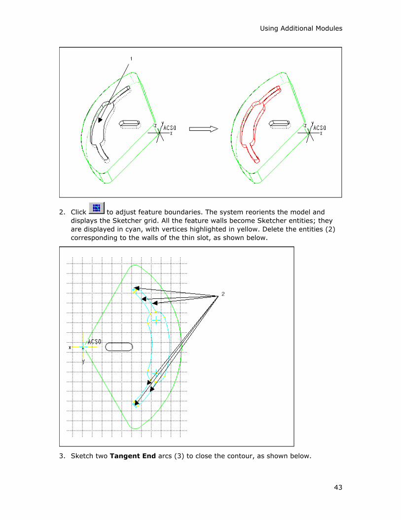
Using Additional Modules
43
2. Click to adjust feature boundaries. The system reorients the model and
displays the Sketcher grid. All the feature walls become Sketcher entities; they
are displayed in cyan, with vertices highlighted in yellow. Delete the entities (2)
corresponding to the walls of the thin slot, as shown below.
3. Sketch two Tangent End arcs (3) to close the contour, as shown below.
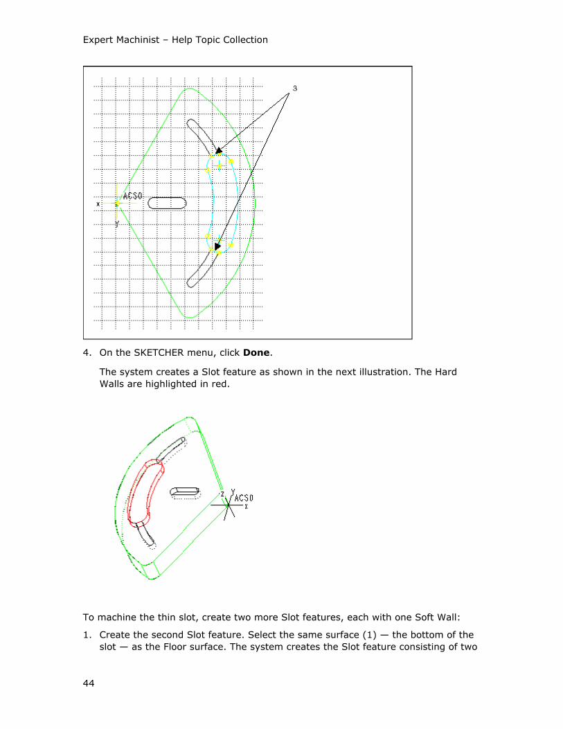
Expert Machinist – Help Topic Collection
44
4. On the SKETCHER menu, click Done.
The system creates a Slot feature as shown in the next illustration. The Hard
Walls are highlighted in red.
To machine the thin slot, create two more Slot features, each with one Soft Wall:
1. Create the second Slot feature. Select the same surface (1) — the bottom of the
slot — as the Floor surface. The system creates the Slot feature consisting of two
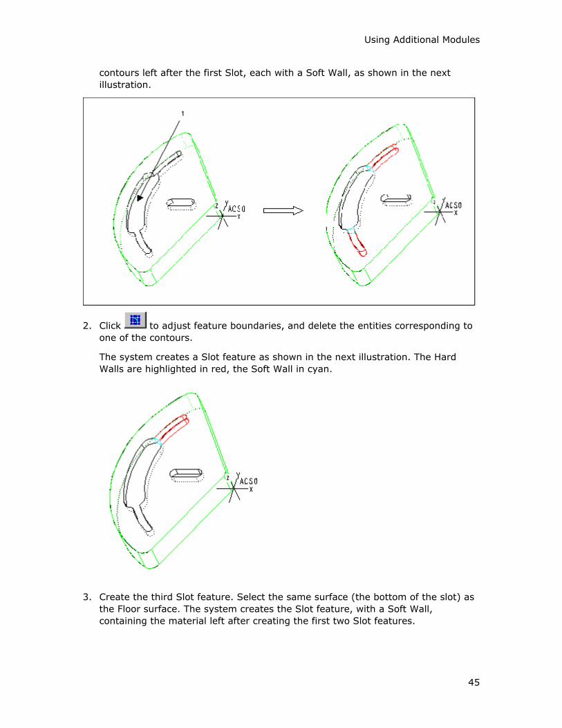
Using Additional Modules
45
contours left after the first Slot, each with a Soft Wall, as shown in the next
illustration.
2. Click to adjust feature boundaries, and delete the entities corresponding to
one of the contours.
The system creates a Slot feature as shown in the next illustration. The Hard
Walls are highlighted in red, the Soft Wall in cyan.
3. Create the third Slot feature. Select the same surface (the bottom of the slot) as
the Floor surface. The system creates the Slot feature, with a Soft Wall,
containing the material left after creating the first two Slot features.
Expert Machinist – Help Topic Collection
46
To Adjust Soft Walls
1. In the machining feature dialog box (for example, Pocket Feature), click
next to the Adjust Soft Walls element.
The system highlights all the feature walls, both Hard and Soft, in magenta.
2. Use the following options on the SELECT SRFS menu:
o Add—Select feature wall surfaces to change them to Soft Walls.
o Remove—Select feature wall surfaces to change them to Hard Walls.
o Show—Highlight the Soft Walls in cyan. Hard Walls stay highlighted in
magenta.
3. Click Done/Return to return to the machining feature dialog box.
To Adjust Feature Depth
1. In the machining feature dialog box (for example, Profile Feature), click
next to the Adjust Feature Bottom element.
The system opens the Define/Adjust Feature Bottom dialog box.
2. Use the following options in the Define/Adjust Feature Bottom dialog box:
o Offset below walls—Type an offset value below the bottom of the stock
(or below the bottom of the feature Hard Walls, for No Stock machining).
o Use Datum Plane—Select or create a datum plane normal to the z-axis of
the Program Zero coordinate system.
o Offset from Program Zero—Type a value along the z-axis of the Program
Zero coordinate system.
o None—The feature Floor coincides with the bottom of the stock. This option
is not available for No Stock machining.
3. Click Preview to highlight the surface currently defining the feature depth in
cyan.
4. Click OK to return to the machining feature dialog box.
To Adjust Feature Top
The Adjust Feature Top element appears only for No Stock machining, that is, for
NC models with no stock defined. For such models, you have to supply a value for
the thickness of material to be removed.
1. In the machining feature dialog box (for example, Profile Feature), click
next to the Adjust Feature Top element.
The system opens the Define/Adjust Feature Top dialog box.
Using Additional Modules
47
2. Use the following options in the Define/Adjust Feature Top dialog box:
o Offset above floor—Type a value of material thickness from the feature
Floor. This option is available only for features with a Hard Floor, such as
Pocket or Step.
o Offset above walls—This option is available only for Through features,
such as Profile, Through Pocket, or Through Slot. By default, the offset
value is 0; that is, the feature top coincides with the top of the feature Hard
Walls. You can type a different offset value, to extend the feature above the
top boundary of the Hard Walls.
o Use Datum Plane—Select or create a datum plane normal to the z-axis of
the Program Zero coordinate system.
o Offset from Program Zero—Type a value along the z-axis of the Program
Zero coordinate system.
3. Click Preview to display the currently defined feature top in cyan.
4. Click OK to return to the machining feature dialog box.
To Machine a Feature
1. On the toolbar, click . Another way to access this functionality is from the top
menu bar: click NC Create > Tool Paths > Machining.
2. Select the feature name in the Select Feature dialog box. As you place the
cursor over a feature name in the dialog box, the appropriate geometry is
highlighted on the screen. Click OK.
The system opens the appropriate machining dialog box, corresponding to the
feature type.
3. Specify the cutting tool, define the machining method and options, and type the
values in the machining dialog box, as needed. For more information on
machining a feature of specific type, get help for the machining dialog box
corresponding to the feature type.
Every machining dialog box contains a Tool Path Properties button. It opens
the Tool Path Properties dialog box, where you can specify feeds and speeds,
as well as general machining, entry/exit, and cut control options.
4. Click Play Path at the bottom of the dialog box to display the currently defined
tool path.
5. Once you have completely defined the tool path for the feature, you can save this
machining strategy as a template, and then apply the template to other features
of the same type.
To save the current machining strategy as a template, click next to the Tool
Path Name text box, then type the template name in the New Name text box
of the Save As dialog box and click OK.
Expert Machinist – Help Topic Collection
48
Note: When you save a machining strategy as a template, it is automatically
saved with the Prompt for a tool option; that is, the template contains no
cutting tool information and the system prompts you to select or define the
cutting tool at the time you apply the template. If you want to modify the
template to always use a specific tool, open the template in Template Manager
and change it there.
6. Click OK to complete machining the feature, Cancel to quit. If you want to use
the same settings to machine a similar type feature, click Next. This will finalize
the creation of the current tool path (equivalent to clicking OK), and then prompt
you to select a feature to be machined using the current settings, similar to the
Mimic Toolpath functionality.
To Set Tool Path Properties
1. In a feature machining dialog box (for example, Pocket Milling), click Tool Path
Properties.
The Tool Path Properties dialog box opens. It contains five tabbed pages: CL
Commands, Feed Rates, Clearance, Entry/Exit, and Cut Control. Each
tabbed page lists the options and values that define your machining strategy.
Initially, the Tool Path Properties dialog box contains either the default system
values, or, if you are placing a machining template or mimicking a Tool Path, the
values from the template or the original Tool Path, respectively.
2. On the appropriate tabs of the Tool Path Properties dialog box, select the
desired options and type values, as needed.
On the Feed Rates tab, each feed rate has two fields: the first one lists the
available methods of specifying this feed rate, the second one is a text box with
the actual value:
o RAPID—The system will output the RAPID command for these moves. The
corresponding Feed Rate text box is then empty and grayed out.
o Enter—Type the desired value in the corresponding Feed Rate text box.
o From Tool—The system retrieves the cutting data stored with the tool.
This option is available only if the tool contains associated cutting data. The
corresponding Feed Rate text box lists the retrieved value and is grayed
out.
The Speed setting on the CL Commands tab and the Depth of Cut and
Stepover settings on the Cut Control tab also have a From Tool option, which
utilizes the cutting data stored with the tool.
3. When you have changed all the necessary settings, click OK.
The system closes the Tool Path Properties dialog box and brings you back to
the feature machining dialog box, where you can verify you selections by clicking
Play Path.

Using Additional Modules
49
Automatic Placement of CL Commands
You can insert a customized CL command anywhere along the tool path by using the
PLAY PATH dialog box. However, if the tool path changes for some reason, the
customized CL command may end up in a wrong location. The Automatic Command
Placement functionality allows you to insert a CL command, or a block of commands,
before or after a specific event on the tool path (for example, before each pass, or
after the final retract), and to maintain its location through subsequent tool path
changes.
The CL Commands tabbed page of the Tool Path Properties dialog box provides
eight typical locations in a CL file where you might want to insert a customized CL
command:
• Before LOADTL—Before the LOADTL statement.
• After LOADTL—After the LOADTL statement.
• After SPINDL—After the SPINDL statement.
• After FROM—After the FROM statement. This option becomes available only if
you select the Use FROM checkbox in the FROM/HOME Statements section,
immediately above the Automatic Command Placement section.
• Before Each Pass—Before the approach move to each cutting pass on the tool
path.
• After Each Pass—After the retract move from each cutting pass on the tool
path.
• After Final Retract—After the final retract move on the tool path. This option is
not available if None is selected as the Final Withdrawal option on the
Clearance tabbed page of the Tool Path Properties dialog box.
• After GOHOME—After the GOHOME statement. This option becomes available
only if you select the Use GOHOME checkbox in the FROM/HOME Statements
section, immediately above the Automatic Command Placement section.
For each of these locations, you can specify a CL command, or a block of CL
commands, by clicking under the location label and then using the CL
Command dialog box. When you are finished, the first command in the block is
displayed in the text box under the location label.
To make the system output the specified commands at the desired location when
writing a CL file, select the checkbox next to the appropriate location label.
To Mimic a Tool Path
Use the Mimic Toolpath functionality when you have an existing tool path and want
to use the same settings on a similar type feature.
1. On the top menu bar, click NC Create > Tool Paths > Mimic a Toolpath.
2. Select the Tool Path feature name in the Select Feature dialog box. Click OK.

Expert Machinist – Help Topic Collection
50
3. Select the feature name in the Select Feature dialog box (only features of the
same type as the one machined by the selected tool path are listed). As you
place the cursor over a feature name in the dialog box, the appropriate geometry
is highlighted on the screen. Click OK.
The system opens the appropriate machining dialog box, with all the settings in
this dialog (except the cutting tool name) copied from the original Tool Path
feature.
Note: Expert Machinist uses the concept of a modal tool; that is, once you
specify a cutting tool, all subsequent machining features will use this tool until
you explicitly change it. (Look in the Index for details on other modal settings in
Expert Machinist.) Therefore, when you mimic a tool path, the system does not
copy the tool information from the Tool Path feature that you mimic; instead, it
uses the modal tool.
4. Change the cutting tool and the selected options, and modify the parameters, if
needed.
5. Click Play Path at the bottom of the dialog box to display the currently defined
tool path.
6. Click OK to complete machining the feature. Once the new tool path is created, it
is completely independent from the original tool path.
Face Features
To Create a Face Feature
1. On the toolbar, click . Another way to access this functionality is from the top
menu bar: click NC Create > Features > Face.
The Face Feature dialog box opens with the following elements:
o Feature Name—The default feature name, such as Face1 (the system
increments the number for the next Face feature). You can type a
customized name.
o Define Feature Floor—Select the Floor surface for the feature (that is, the
top surface of the reference model).
o Define Program Zero—Change the coordinate system used for feature
definition and machining.
2. Select the Floor surface. On the SELECT SRFS menu, click Done/Return.
3. Change Program Zero, if needed. Click next to the element to display the
current setting. The Preview button lets you check the feature geometry by
highlighting the Soft Walls in cyan.
4. Click OK to complete the feature, Cancel to quit.
Using Additional Modules
51
To Machine a Face Feature
1. On the toolbar, click . Another way to access this functionality is from the top
menu bar: click NC Create > Tool Paths > Machining.
2. Select the feature name in the Select Feature dialog box. As you place the
cursor over a feature name in the dialog box, the appropriate geometry is
highlighted on the screen. Click OK.
The system opens the Face Milling dialog box. The top portion of the dialog box
contains three text boxes:
o Tool Path Name—The default name for the tool path file, such as
FACE1_TP1 (the system uses the name of the feature for the first portion of
the tool path name). The system will use this file name for NC data output.
You can type a customized name. You can also click the Comments button
located under the Tool Path Name text box to type the Machine Strategy
Comments.
o Feature Name—The name of the feature being machined. This name is
displayed for information purposes only; you cannot change it. You can click
the Preview button located under the Feature Name text box to highlight
the feature geometry.
o Cutting Tool—The name of the cutting tool. When you use a Machine Tool
for the first time within the NC process, there is no active tool and the text
box displays None. For subsequent machining, the text box displays the
name of the active tool.
The middle portion of the Face Milling dialog box contains the options for
defining the Machining Method, and the lower portion lists the machining Options.
At the bottom of the dialog box there are four buttons: OK, Cancel, Next, and
Play Path.
3. Change the cutting tool, if needed. You have to specify a tool name if there is no
active tool.
If the Machine Tool has preset cutting tools, select the tool you want by clicking
on the drop-down arrow and selecting the tool name from the drop-down list.
To access the Cutting Tool Manager, click next to the Cutting Tool text
box. This functionality lets you create new tools and modify existing ones.
Click Show Tool below the Cutting Tool text box to display the currently
selected tool in a pop-up window.
4. Define the Machining Method and Options, as needed, by selecting options and
typing values in the middle and lower portions of the dialog box. Click Play Path
at the bottom of the dialog box to display the currently defined tool path.
5. Click OK to complete machining the feature, Cancel to quit. If you want to use
the same settings to machine a similar feature, click Next.
Expert Machinist – Help Topic Collection
52
The Face Milling Dialog Box
The Machining Method section of the Face Milling dialog box contains the following
options.
Machining Mode
• Rough—Face down the stock and leave stock according to the Rough to value.
• Finish—Finish mill the reference model surface(s). When you select this option,
you can use the Finish Passes button to set up the number of finish passes and
the depth increments.
Cut Motion
These options define the cut direction:
• One Direction—The tool cuts in one direction only. At the end of each cut, the
tool returns to the opposite side, to start the next cut in the same direction.
• Back and Forth—The tool continuously machines the Face feature, moving back
and forth. At the end of a pass, it retracts and moves to the beginning of the next
pass, unless the Reverse Multiple Passes option is selected.
• Spiral—Generates a spiral cutting path.
These options define where material is relative to the tool rotation:
• Climb—The tool is to the left of material (assuming clockwise spindle rotation).
• Conventional—The tool is to the right of material (assuming clockwise spindle
rotation).
Cut Angle—Defines the angle between the cut direction and the x-axis of the
Program Zero coordinate system for One Direction and Back and Forth cut motion
types. The default is 0, which means that the tool cuts parallel to the x-axis of the
Program Zero coordinate system. To change the cut direction, type the new value in
the Cut Angle text box.
Motion Between Cuts
These options describe the way the tool makes the horizontal connections between
the cutting motions:
• Clear Part—The tool clears the Soft Walls when exiting and entering the material
for each cut.
• Stay in Cut—The tool stays engaged in material between cuts.
• Clear Part on Last Cut—If Stay in Cut is selected, this option will make the
tool clear the part on the final cut of each pass.
These options describe whether the tool retracts when connecting the cutting
motions:
• Stay Down—The tool does not retract between the cut motions.
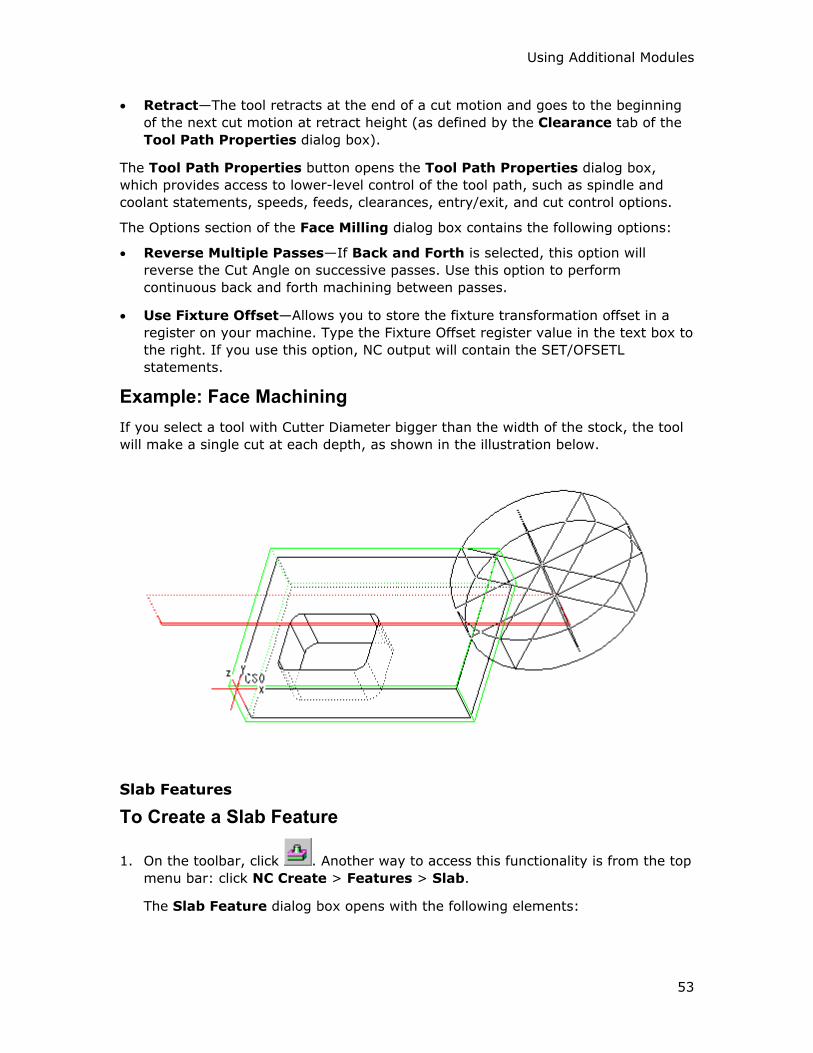
Using Additional Modules
53
• Retract—The tool retracts at the end of a cut motion and goes to the beginning
of the next cut motion at retract height (as defined by the Clearance tab of the
Tool Path Properties dialog box).
The Tool Path Properties button opens the Tool Path Properties dialog box,
which provides access to lower-level control of the tool path, such as spindle and
coolant statements, speeds, feeds, clearances, entry/exit, and cut control options.
The Options section of the Face Milling dialog box contains the following options:
• Reverse Multiple Passes—If Back and Forth is selected, this option will
reverse the Cut Angle on successive passes. Use this option to perform
continuous back and forth machining between passes.
• Use Fixture Offset—Allows you to store the fixture transformation offset in a
register on your machine. Type the Fixture Offset register value in the text box to
the right. If you use this option, NC output will contain the SET/OFSETL
statements.
Example: Face Machining
If you select a tool with Cutter Diameter bigger than the width of the stock, the tool
will make a single cut at each depth, as shown in the illustration below.
Slab Features
To Create a Slab Feature
1. On the toolbar, click . Another way to access this functionality is from the top
menu bar: click NC Create > Features > Slab.
The Slab Feature dialog box opens with the following elements:
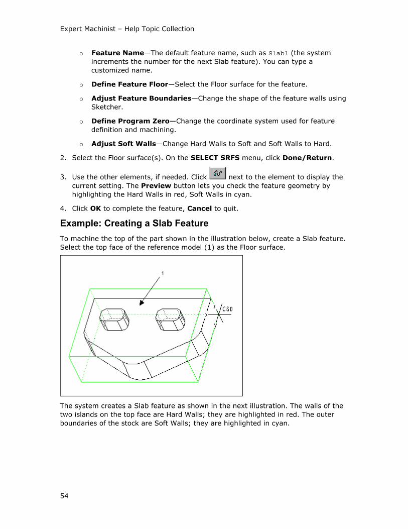
Expert Machinist – Help Topic Collection
54
o Feature Name—The default feature name, such as Slab1 (the system
increments the number for the next Slab feature). You can type a
customized name.
o Define Feature Floor—Select the Floor surface for the feature.
o Adjust Feature Boundaries—Change the shape of the feature walls using
Sketcher.
o Define Program Zero—Change the coordinate system used for feature
definition and machining.
o Adjust Soft Walls—Change Hard Walls to Soft and Soft Walls to Hard.
2. Select the Floor surface(s). On the SELECT SRFS menu, click Done/Return.
3. Use the other elements, if needed. Click next to the element to display the
current setting. The Preview button lets you check the feature geometry by
highlighting the Hard Walls in red, Soft Walls in cyan.
4. Click OK to complete the feature, Cancel to quit.
Example: Creating a Slab Feature
To machine the top of the part shown in the illustration below, create a Slab feature.
Select the top face of the reference model (1) as the Floor surface.
The system creates a Slab feature as shown in the next illustration. The walls of the
two islands on the top face are Hard Walls; they are highlighted in red. The outer
boundaries of the stock are Soft Walls; they are highlighted in cyan.
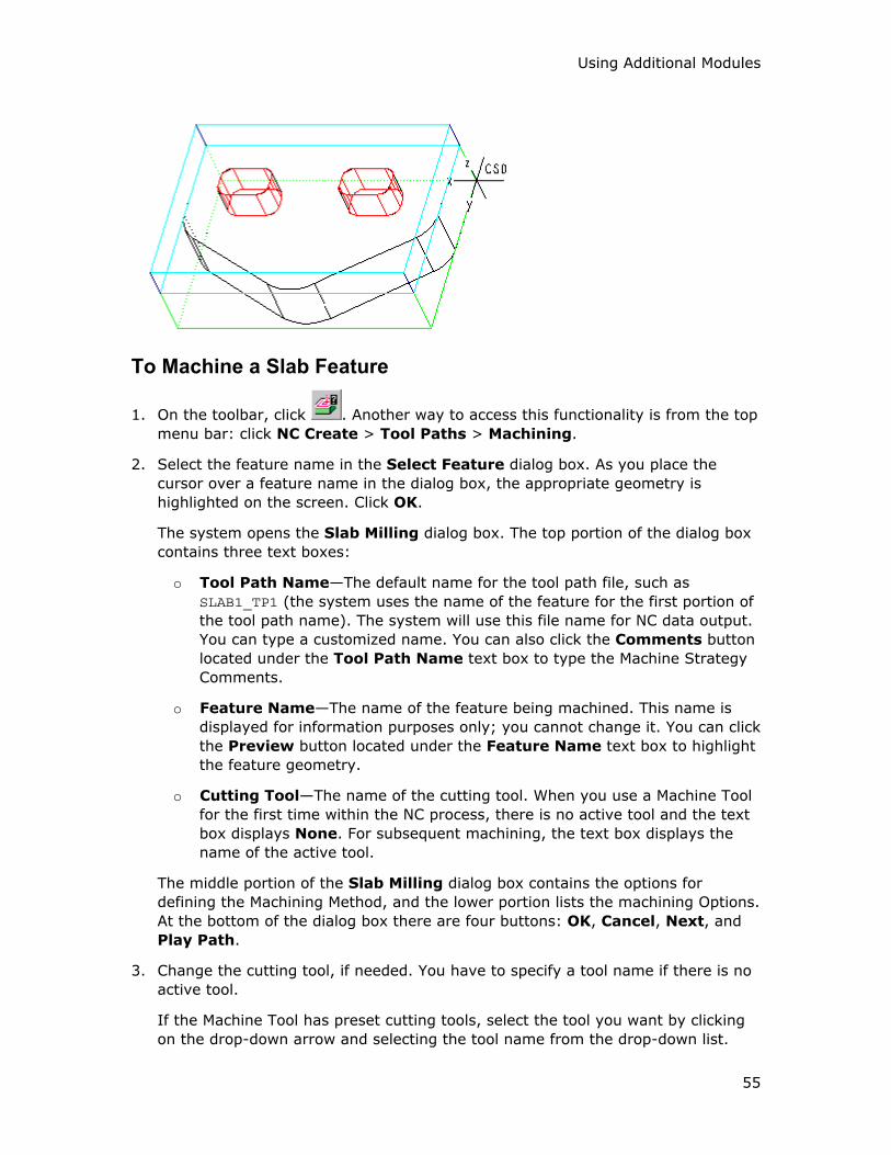
Using Additional Modules
55
To Machine a Slab Feature
1. On the toolbar, click . Another way to access this functionality is from the top
menu bar: click NC Create > Tool Paths > Machining.
2. Select the feature name in the Select Feature dialog box. As you place the
cursor over a feature name in the dialog box, the appropriate geometry is
highlighted on the screen. Click OK.
The system opens the Slab Milling dialog box. The top portion of the dialog box
contains three text boxes:
o Tool Path Name—The default name for the tool path file, such as
SLAB1_TP1 (the system uses the name of the feature for the first portion of
the tool path name). The system will use this file name for NC data output.
You can type a customized name. You can also click the Comments button
located under the Tool Path Name text box to type the Machine Strategy
Comments.
o Feature Name—The name of the feature being machined. This name is
displayed for information purposes only; you cannot change it. You can click
the Preview button located under the Feature Name text box to highlight
the feature geometry.
o Cutting Tool—The name of the cutting tool. When you use a Machine Tool
for the first time within the NC process, there is no active tool and the text
box displays None. For subsequent machining, the text box displays the
name of the active tool.
The middle portion of the Slab Milling dialog box contains the options for
defining the Machining Method, and the lower portion lists the machining Options.
At the bottom of the dialog box there are four buttons: OK, Cancel, Next, and
Play Path.
3. Change the cutting tool, if needed. You have to specify a tool name if there is no
active tool.
If the Machine Tool has preset cutting tools, select the tool you want by clicking
on the drop-down arrow and selecting the tool name from the drop-down list.

Expert Machinist – Help Topic Collection
56
To access the Cutting Tool Manager, click next to the Cutting Tool text
box. This functionality lets you create new tools and modify existing ones.
Click Show Tool below the Cutting Tool text box to display the currently
selected tool in a pop-up window.
4. Define the Machining Method and Options, as needed, by selecting options and
typing values in the middle and lower portions of the dialog box. Click Play Path
at the bottom of the dialog box to display the currently defined tool path.
5. Click OK to complete machining the feature, Cancel to quit. If you want to use
the same settings to machine a similar feature, click Next.
The Slab Milling Dialog Box
The Machining Method section of the Slab Milling dialog box contains the following
options.
Roughing
Rough Slab—Remove the material inside the Slab feature using rough milling and
leaving stock according to the Floor Stock and Wall Stock values:
• Floor Stock—Stock to be left on the Floor surfaces.
• Wall Stock—Stock to be left on the Hard Walls.
Finishing
• Finish Floors—Finish mill the Floor surfaces. When you select this option, you
can use the Finish Passes button to set up the number of finish passes and the
depth increments.
• Back Off Walls—When you do rough milling and finish floors within the same
tool path, you can keep the tool off the walls by a specified additional distance
while the Floor is being finished. You can then finish the walls later. This option
becomes available when both the Rough Slab and Finish Floors options are
selected and the Finish Walls option is cleared. When you select this option,
type the back-off distance in the text box to the right.
• Finish Walls—Finish mill the Hard Walls. When you select this option, you can
use the Finish Cuts button to set up the number of finish cuts and the depth
increments.
• Use CUTCOM—NC output will contain the CUTCOM statements. You can
customize their format and locations by clicking the Tool Path Properties
button and using the Cut Control tab of the Tool Path Properties dialog box.
Cut Motion
These options define the cut direction:
• One Direction—The tool cuts in one direction only. At the end of each cutting
pass, the tool returns to the opposite side, to start the next pass in the same
direction.
Using Additional Modules
57
• Back and Forth—The tool continuously machines the Slab feature, moving back
and forth. At the end of a pass, it retracts and moves to the beginning of the next
pass, unless the Reverse Multiple Passes option is selected.
These options define where material is relative to the tool rotation:
• Climb—The tool is to the left of material (assuming clockwise spindle rotation).
• Conventional—The tool is to the right of material (assuming clockwise spindle
rotation).
Cut Angle—Defines the angle between the cut direction and the x-axis of the
Program Zero coordinate system. The default is 0, which means that the tool cuts
parallel to the x-axis of the Program Zero coordinate system. To change the cut
direction, type the new value in the Cut Angle text box.
Clean Up Cut—Cleans up the Hard Walls after the rough cut and before the finish
cuts, to remove scallops left by the rough cut. Type the value for the minimal
amount of stock to be removed by this cut in the Stock text box to the right.
Connect Motions
These options describe the way the tool makes the horizontal connections between
the cutting motions:
• Clear Part—The tool clears the Soft Walls when exiting and entering the material
for each cut.
• Stay in Cut—The tool stays engaged in material between cuts.
These options describe whether the tool retracts when connecting the cutting
motions:
• Stay Down—The tool does not retract between the cut motions.
• Retract—The tool retracts at the end of a cut motion and goes to the beginning
of the next cut motion at retract height (as defined by the Clearance tab of the
Tool Path Properties dialog box).
The Tool Path Properties button opens the Tool Path Properties dialog box,
which provides access to lower-level control of the tool path, such as spindle and
coolant statements, speeds, feeds, clearances, entry/exit, and cut control options.
The Options section of the Slab Milling dialog box contains the following options:
• Reverse Multiple Passes—If Back and Forth is selected, this option will
reverse the Cut Angle on successive passes. Use this option to perform
continuous back and forth machining between passes.
• Use Fixture Offset—Allows you to store the fixture transformation offset in a
register on your machine. Type the Fixture Offset register value in the text box to
the right. If you use this option, NC output will contain the SET/OFSETL
statements.
Expert Machinist – Help Topic Collection
58
Pocket Features
To Create a Pocket Feature
1. On the toolbar, click . Another way to access this functionality is from the top
menu bar: click NC Create > Features > Pocket.
The Pocket Feature dialog box opens with the following elements:
o Feature Name—The default feature name, such as Pocket1 (the system
increments the number for the next Pocket feature). You can type a
customized name.
o Define Feature Floor—Select the Floor surface for the feature.
o Adjust Feature Boundaries—Change the shape of the feature walls using
Sketcher.
o Define Program Zero—Change the coordinate system used for feature
definition and machining.
o Adjust Soft Walls—Change Hard Walls to Soft and Soft Walls to Hard.
2. Select the Floor surface(s). On the SELECT SRFS menu, click Done/Return.
3. Use the other elements, if needed. Click next to the element to display the
current setting. The Preview button lets you check the feature geometry by
highlighting the Hard Walls in red, Soft Walls in cyan.
4. Click OK to complete the feature, Cancel to quit.
To Machine a Pocket Feature
1. On the toolbar, click . Another way to access this functionality is from the top
menu bar: click NC Create > Tool Paths > Machining.
2. Select the feature name in the Select Feature dialog box. As you place the
cursor over a feature name in the dialog box, the appropriate geometry is
highlighted on the screen. Click OK.
The system opens the Pocket Milling dialog box. The top portion of the dialog
box contains three text boxes:
o Tool Path Name—The default name for the tool path file, such as
POCKET1_TP1 (the system uses the name of the feature for the first portion
of the tool path name). The system will use this file name for NC data
output. You can type a customized name. You can also click the Comments
button located under the Tool Path Name text box to type the Machine
Strategy Comments.
o Feature Name—The name of the feature being machined. This name is
displayed for information purposes only; you cannot change it. You can click

Using Additional Modules
59
the Preview button located under the Feature Name text box to highlight
the feature geometry.
o Cutting Tool—The name of the cutting tool. When you use a Machine Tool
for the first time within the NC process, there is no active tool and the text
box displays None. For subsequent machining, the text box displays the
name of the active tool.
The middle portion of the Pocket Milling dialog box contains the options for
defining the Machining Method, and the lower portion lists the machining Options.
At the bottom of the dialog box there are four buttons: OK, Cancel, Next, and
Play Path.
3. Change the cutting tool, if needed. You have to specify a tool name if there is no
active tool.
If the Machine Tool has preset cutting tools, select the tool you want by clicking
on the drop-down arrow and selecting the tool name from the drop-down list.
To access the Cutting Tool Manager, click next to the Cutting Tool text
box. This functionality lets you create new tools and modify existing ones.
Click Show Tool below the Cutting Tool text box to display the currently
selected tool in a pop-up window.
4. Define the Machining Method and Options, as needed, by selecting options and
typing values in the middle and lower portions of the dialog box. Click Play Path
at the bottom of the dialog box to display the currently defined tool path.
5. Click OK to complete machining the feature, Cancel to quit. If you want to use
the same settings to machine a similar feature, click Next.
The Pocket Milling Dialog Box
The Machining Method section of the Pocket Milling dialog box contains the
following options.
Roughing
Rough Pocket—Remove material inside the pocket using rough milling and leaving
stock according to the Floor Stock and Wall Stock values:
• Floor Stock—Stock to be left on the Floor of the pocket.
• Wall Stock—Stock to be left on the walls of the pocket.
Finishing
• Finish Floors—Finish mill the Floor of the pocket. When you select this option,
you can use the Finish Passes button to set up the number of finish passes and
the depth increments.
• Back Off Walls—When you do rough pocket milling and finish floors within the
same tool path, you can keep the tool off the walls by a specified additional
distance while the Floor is being finished. You can then finish the walls later. This
Expert Machinist – Help Topic Collection
60
option becomes available when both the Rough Pocket and Finish Floors
options are selected and the Finish Walls option is cleared. When you select this
option, type the back-off distance in the text box to the right.
• Finish Walls—Finish mill the walls of the pocket. When you select this option,
you can use the Finish Cuts button to set up the number of finish cuts and the
depth increments.
• Corners Only—Clean up the corners with a smaller tool after removing material
from the pocket with a large tool.
• Use CUTCOM—NC output will contain the CUTCOM statements. You can
customize their format and locations by clicking the Tool Path Properties
button and using the Cut Control tab of the Tool Path Properties dialog box.
Cut Motion
These options define the way the tool scans the horizontal cross-sections of the
pocket:
• One Direction—Cuts in one direction only. At the end of each cut, the tool
retracts and returns to the opposite side of the pocket, to start the next cut in
the same direction.
• Back and Forth—Continuously machines the pocket, moving back and forth.
• Spiral—Generates a spiral cutting path.
These options define where material is relative to the tool rotation:
• Climb—The tool is to the left of material (assuming clockwise spindle rotation).
• Conventional—The tool is to the right of material (assuming clockwise spindle
rotation).
Cut Angle—Defines the angle between the cut direction and the x-axis of the
Program Zero coordinate system for One Direction and Back and Forth cut motion
types. The default is 0, which means that the tool cuts parallel to the x-axis of the
Program Zero coordinate system. To change the cut direction, type the new value in
the Cut Angle text box.
Clean Up Cut—Cleans up the walls of the pocket after the rough cut and before the
finish cuts, to remove scallops left by the rough cut. Type the value for the minimal
amount of stock to be removed by this cut in the Stock text box to the right.
Top Entry
These options describe the way the tool enters the pocket:
• Plunge—The tool enters the material vertically.
• Ramp—The tool enters at Ramp Angle to the x-axis of the Program Zero
coordinate system. You can customize the Ramp Angle by clicking the Tool
Path Properties button and using the Entry/Exit tab of the Tool Path
Properties dialog box.
Using Additional Modules
61
• Helix—The tool enters along a helical path. You can customize the helical entry
by clicking the Tool Path Properties button and using the Entry/Exit tab of the
Tool Path Properties dialog box. Type the new values for the Helix Angle and
the Radius of the helix (the default for which is calculated by the system based
on the size of the part).
• Entry Hole—The tool enters along a predefined entry hole. To use this option,
you must first create and machine an Entry Hole feature for this pocket.
The Tool Path Properties button opens the Tool Path Properties dialog box,
which provides access to lower-level control of the tool path, such as spindle and
coolant statements, speeds, feeds, clearances, entry/exit, and cut control options.
The Options section of the Pocket Milling dialog box contains the following option:
Use Fixture Offset—Allows you to store the fixture transformation offset in a
register on your machine. Type the Fixture Offset register value in the text box to
the right. If you use this option, NC output will contain the SET/OFSETL statements.
Through Pocket Features
To Create a Through Pocket Feature
1. On the toolbar, click . Another way to access this functionality is from the top
menu bar: click NC Create > Features > Thru Pocket.
The Through Pocket Feature dialog box opens with the following elements:
o Feature Name—The default feature name, such as Thru Pocket1 (the
system increments the number for the next Through Pocket feature). You
can type a customized name.
o Define Feature Walls—Select the side surfaces to be machined.
o Adjust Feature Boundaries—Change the shape of the feature walls using
Sketcher.
o Define Program Zero—Change the coordinate system used for feature
definition and machining.
o Adjust Soft Walls—Change Hard Walls to Soft and Soft Walls to Hard.
o Adjust Feature Bottom—Adjust the Floor depth of feature (by default, a
Through Pocket extends all the way through the stock). To specify a
different Floor depth, select a surface, a datum plane, or type a value along
the z-axis of the feature-level Program Zero coordinate system.
2. Select the walls of the pocket. Use the following commands on the SURF/LOOP
menu:
o Surface—Select the wall surfaces individually.
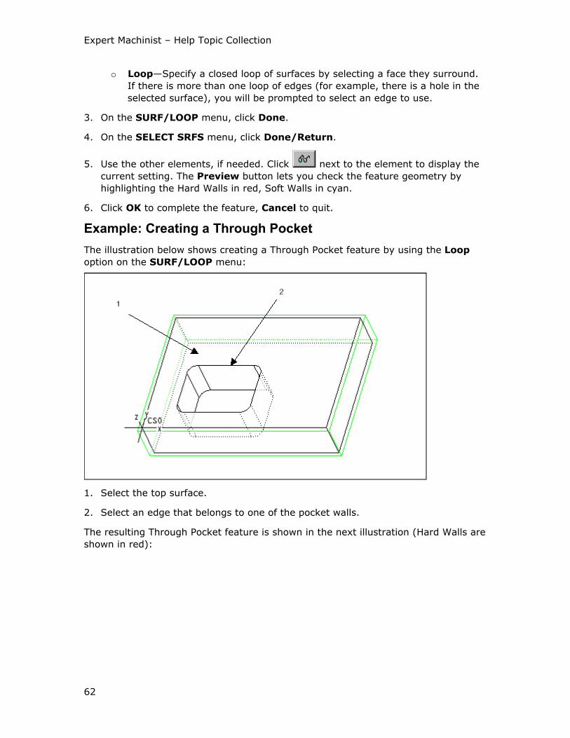
Expert Machinist – Help Topic Collection
62
o Loop—Specify a closed loop of surfaces by selecting a face they surround.
If there is more than one loop of edges (for example, there is a hole in the
selected surface), you will be prompted to select an edge to use.
3. On the SURF/LOOP menu, click Done.
4. On the SELECT SRFS menu, click Done/Return.
5. Use the other elements, if needed. Click next to the element to display the
current setting. The Preview button lets you check the feature geometry by
highlighting the Hard Walls in red, Soft Walls in cyan.
6. Click OK to complete the feature, Cancel to quit.
Example: Creating a Through Pocket
The illustration below shows creating a Through Pocket feature by using the Loop
option on the SURF/LOOP menu:
1. Select the top surface.
2. Select an edge that belongs to one of the pocket walls.
The resulting Through Pocket feature is shown in the next illustration (Hard Walls are
shown in red):
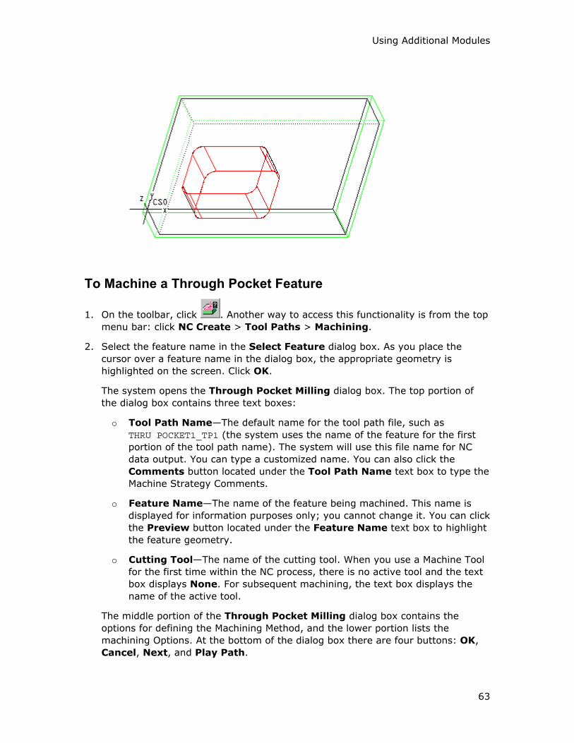
Using Additional Modules
63
To Machine a Through Pocket Feature
1. On the toolbar, click . Another way to access this functionality is from the top
menu bar: click NC Create > Tool Paths > Machining.
2. Select the feature name in the Select Feature dialog box. As you place the
cursor over a feature name in the dialog box, the appropriate geometry is
highlighted on the screen. Click OK.
The system opens the Through Pocket Milling dialog box. The top portion of
the dialog box contains three text boxes:
o Tool Path Name—The default name for the tool path file, such as
THRU POCKET1_TP1 (the system uses the name of the feature for the first
portion of the tool path name). The system will use this file name for NC
data output. You can type a customized name. You can also click the
Comments button located under the Tool Path Name text box to type the
Machine Strategy Comments.
o Feature Name—The name of the feature being machined. This name is
displayed for information purposes only; you cannot change it. You can click
the Preview button located under the Feature Name text box to highlight
the feature geometry.
o Cutting Tool—The name of the cutting tool. When you use a Machine Tool
for the first time within the NC process, there is no active tool and the text
box displays None. For subsequent machining, the text box displays the
name of the active tool.
The middle portion of the Through Pocket Milling dialog box contains the
options for defining the Machining Method, and the lower portion lists the
machining Options. At the bottom of the dialog box there are four buttons: OK,
Cancel, Next, and Play Path.
Expert Machinist – Help Topic Collection
64
3. Change the cutting tool, if needed. You have to specify a tool name if there is no
active tool.
If the Machine Tool has preset cutting tools, select the tool you want by clicking
on the drop-down arrow and selecting the tool name from the drop-down list.
To access the Cutting Tool Manager, click next to the Cutting Tool text
box. This functionality lets you create new tools and modify existing ones.
Click Show Tool below the Cutting Tool text box to display the currently
selected tool in a pop-up window.
4. Define the Machining Method and Options, as needed, by selecting options and
typing values in the middle and lower portions of the dialog box. Click Play Path
at the bottom of the dialog box to display the currently defined tool path.
5. Click OK to complete machining the feature, Cancel to quit. If you want to use
the same settings to machine a similar feature, click Next.
The Through Pocket Milling Dialog Box
The Machining Method section of the Through Pocket Milling dialog box contains
the following options.
Wall Machining
• Rough—Remove material inside the pocket using rough milling and leaving stock
on the walls of the pocket according to the Rough to value.
• Finish—Finish mill the walls of the pocket. When you select this option, you can
use the Finish Cuts button to set up the number of finish cuts and the depth
increments.
• Use CUTCOM—NC output will contain the CUTCOM statements. You can
customize their format and locations by clicking the Tool Path Properties
button and using the Cut Control tab of the Tool Path Properties dialog box.
Cut Motion
These options define the way the tool scans the horizontal cross-sections of the
pocket:
• One Direction—Cuts in one direction only. At the end of each cutting pass, the
tool retracts and returns to the opposite side if the pocket, to start the next pass
in the same direction.
• Back and Forth—Continuously machines the pocket, moving back and forth.
• Spiral—Generates a spiral cutting path.
These options define where material is relative to the tool rotation:
• Climb—The tool is to the left of material (assuming clockwise spindle rotation).
• Conventional—The tool is to the right of material (assuming clockwise spindle
rotation).

Using Additional Modules
65
Cut Angle—Defines the angle between the cut direction and the x-axis of the
Program Zero coordinate system for One Direction and Back and Forth cut motion
types. The default is 0, which means that the tool cuts parallel to the x-axis of the
Program Zero coordinate system. To change the cut direction, type the new value in
the Cut Angle text box.
Clean Up Cut—Cleans up the walls of the pocket after the rough cut and before the
finish cuts, to remove scallops left by the rough cut. Type the value for the minimal
amount of stock to be removed by this cut in the Stock text box to the right.
Top Entry
These options describe the way the tool enters the pocket:
• Plunge—The tool enters the material vertically.
• Ramp—The tool enters at Ramp Angle to the x-axis of the Program Zero
coordinate system. You can customize the Ramp Angle by clicking the Tool
Path Properties button and using the Entry/Exit tab of the Tool Path
Properties dialog box.
• Helix—The tool enters along a helical path. You can customize the helical entry
by clicking the Tool Path Properties button and using the Entry/Exit tab of the
Tool Path Properties dialog box. Type the new values for the Helix Angle and
the Radius of the helix (the default for which is calculated by the system based
on the size of the part).
• Entry Hole—The tool enters along a predefined entry hole. To use this option,
you must first create and machine an Entry Hole feature for this pocket.
The Tool Path Properties button opens the Tool Path Properties dialog box,
which provides access to lower-level control of the tool path, such as spindle and
coolant statements, speeds, feeds, clearances, entry/exit, and cut control options.
The Options section of the Through Pocket Milling dialog box contains the
following option:
Use Fixture Offset—Allows you to store the fixture transformation offset in a
register on your machine. Type the Fixture Offset register value in the text box to
the right. If you use this option, NC output will contain the SET/OFSETL statements.
Step Features
To Create a Step Feature
1. On the toolbar, click . Another way to access this functionality is from the top
menu bar: click NC Create > Features > Step.
The Step Feature dialog box opens with the following elements:
o Feature Name—The default feature name, such as Step1 (the system
increments the number for the next Step feature). You can type a
customized name.
o Define Feature Floor—Select the Floor surface for the feature.
Expert Machinist – Help Topic Collection
66
o Adjust Feature Boundaries—Change the shape of the feature walls using
Sketcher.
o Define Program Zero—Change the coordinate system used for feature
definition and machining.
o Adjust Soft Walls—Change Hard Walls to Soft and Soft Walls to Hard.
o Adjust Feature Bottom—Adjust the Floor depth of feature. Select a
surface, a datum plane, or type a value along the z-axis of the feature-level
Program Zero coordinate system.
2. Select the Floor surface(s). On the SELECT SRFS menu, click Done/Return.
3. Use the other elements, if needed. Click next to the element to display the
current setting. The Preview button lets you check the feature geometry by
highlighting the Hard Walls in red, Soft Walls in cyan.
4. Click OK to complete the feature, Cancel to quit.
To Machine a Step Feature
1. On the toolbar, click . Another way to access this functionality is from the top
menu bar: click NC Create > Tool Paths > Machining.
2. Select the feature name in the Select Feature dialog box. As you place the
cursor over a feature name in the dialog box, the appropriate geometry is
highlighted on the screen. Click OK.
The system opens the Step Milling dialog box. The top portion of the dialog box
contains three text boxes:
o Tool Path Name—The default name for the tool path file, such as
STEP1_TP1 (the system uses the name of the feature for the first portion of
the tool path name). The system will use this file name for NC data output.
You can type a customized name. You can also click the Comments button
located under the Tool Path Name text box to type the Machine Strategy
Comments.
o Feature Name—The name of the feature being machined. This name is
displayed for information purposes only; you cannot change it. You can click
the Preview button located under the Feature Name text box to highlight
the feature geometry.
o Cutting Tool—The name of the cutting tool. When you use a Machine Tool
for the first time within the NC process, there is no active tool and the text
box displays None. For subsequent machining, the text box displays the
name of the active tool.
The middle portion of the Step Milling dialog box contains the options for
defining the Machining Method, and the lower portion lists the machining Options.
At the bottom of the dialog box there are four buttons: OK, Cancel, Next, and
Play Path.
Using Additional Modules
67
3. Change the cutting tool, if needed. You have to specify a tool name if there is no
active tool.
If the Machine Tool has preset cutting tools, select the tool you want by clicking
on the drop-down arrow and selecting the tool name from the drop-down list.
To access the Cutting Tool Manager, click next to the Cutting Tool text
box. This functionality lets you create new tools and modify existing ones.
Click Show Tool below the Cutting Tool text box to display the currently
selected tool in a pop-up window.
4. Define the Machining Method and Options, as needed, by selecting options and
typing values in the middle and lower portions of the dialog box. Click Play Path
at the bottom of the dialog box to display the currently defined tool path.
5. Click OK to complete machining the feature, Cancel to quit. If you want to use
the same settings to machine a similar feature, click Next.
The Step Milling Dialog Box
The Machining Method section of the Step Milling dialog box contains the following
options.
Roughing
Rough Step—Remove the material inside the Step feature using rough milling and
leaving stock according to the Floor Stock and Wall Stock values:
• Floor Stock—Stock to be left on the Floor surfaces.
• Wall Stock—Stock to be left on the Hard Walls.
Finishing
• Finish Floors—Finish mill the Floor surfaces. When you select this option, you
can use the Finish Passes button to set up the number of finish passes and the
depth increments.
• Back Off Walls—When you do rough milling and finish floors within the same
tool path, you can keep the tool off the walls by a specified additional distance
while the Floor is being finished. You can then finish the walls later. This option
becomes available when both the Rough Step and Finish Floors options are
selected and the Finish Walls option is cleared. When you select this option,
type the back-off distance in the text box to the right.
• Finish Walls—Finish mill the Hard Walls. When you select this option, you can
use the Finish Cuts button to set up the number of finish cuts and the depth
increments.
• Use CUTCOM—NC output will contain the CUTCOM statements. You can
customize their format and locations by clicking the Tool Path Properties
button and using the Cut Control tab of the Tool Path Properties dialog box.
Expert Machinist – Help Topic Collection
68
Cut Motion
These options define the cut direction:
• One Direction—The tool cuts in one direction only. At the end of each cut, the
tool returns to the opposite side, to start the next cut in the same direction.
• Back and Forth—The tool continuously machines the Step feature, moving back
and forth.
These options define where material is relative to the tool rotation:
• Climb—The tool is to the left of material (assuming clockwise spindle rotation).
• Conventional—The tool is to the right of material (assuming clockwise spindle
rotation).
These options define the cutting direction:
• Follow Hard Walls—The tool follows the shape of the Hard Walls.
• Straight Line—The tool cuts straight at a constant angle to the Program Zero
coordinate system.
Cut Angle—Defines the angle between the cut direction and the x-axis of the
feature-level Program Zero coordinate system if Straight Line is selected. The
default is 0, which means that the tool cuts parallel to the x-axis of the Program Zero
coordinate system. To change the cut direction, type the new value in the Cut Angle
text box.
Clean Up Cut—Cleans up the Hard Walls after the rough cut and before the finish
cuts, to remove scallops left by the rough cut. Type the value for the minimal
amount of stock to be removed by this cut in the Stock text box to the right.
Connect Motions
These options describe the way the tool makes the horizontal connections between
the cutting motions:
• Clear Part—The tool clears the Soft Walls when exiting and entering the material
for each cut.
• Stay in Cut—The tool stays engaged in material between cuts.
These options describe whether the tool retracts when connecting the cutting
motions:
• Stay Down—The tool does not retract between the cut motions.
• Retract—The tool retracts at the end of a cut motion and goes to the beginning
of the next cut motion at retract height (as defined by the Clearance tab of the
Tool Path Properties dialog box).
The Tool Path Properties button opens the Tool Path Properties dialog box,
which provides access to lower-level control of the tool path, such as spindle and
coolant statements, speeds, feeds, clearances, entry/exit, and cut control options.
The Options section of the Step Milling dialog box contains the following option:
Using Additional Modules
69
Use Fixture Offset—Allows you to store the fixture transformation offset in a
register on your machine. Type the Fixture Offset register value in the text box to
the right. If you use this option, NC output will contain the SET/OFSETL statements.
Profile Features
To Create a Profile Feature
1. On the toolbar, click . Another way to access this functionality is from the top
menu bar: click NC Create > Features > Profile.
The Profile Feature dialog box opens with the following elements:
o Feature Name—The default feature name, such as Profile1 (the system
increments the number for the next Profile feature). You can type a
customized name.
o Define Feature Walls—Select the side surfaces to be machined.
o Adjust Feature Boundaries—Change the shape of the feature walls using
Sketcher.
o Define Program Zero—Change the coordinate system used for feature
definition and machining.
o Adjust Soft Walls—Change Hard Walls to Soft and Soft Walls to Hard.
o Adjust Feature Bottom—Adjust the Floor depth of feature (by default, a
Profile extends all the way through the stock). To specify a different Floor
depth, select a surface, a datum plane, or type a value along the z-axis of
the feature-level Program Zero coordinate system.
2. Select the Hard Walls. Use the following commands on the SURF/LOOP menu:
o Surface—Select the wall surfaces individually.
o Loop—Specify a closed loop of surfaces by selecting a face they surround.
If there is more than one loop of edges (for example, there is a hole in the
selected surface), you will be prompted to select an edge to use.
3. On the SURF/LOOP menu, click Done.
4. On the SELECT SRFS menu, click Done/Return.
5. Use the other elements, if needed. Click next to the element to display the
current setting. The Preview button lets you check the feature geometry by
highlighting the Hard Walls in red, Soft Walls in cyan.
6. Click OK to complete the feature, Cancel to quit.
Expert Machinist – Help Topic Collection
70
To Machine a Profile Feature
1. On the toolbar, click . Another way to access this functionality is from the top
menu bar: click NC Create > Tool Paths > Machining.
2. Select the feature name in the Select Feature dialog box. As you place the
cursor over a feature name in the dialog box, the appropriate geometry is
highlighted on the screen. Click OK.
The system opens the Profile Milling dialog box. The top portion of the dialog
box contains three text boxes:
o Tool Path Name—The default name for the tool path file, such as
PROFILE1_TP1 (the system uses the name of the feature for the first portion
of the tool path name). The system will use this file name for NC data
output. You can type a customized name. You can also click the Comments
button located under the Tool Path Name text box to type the Machine
Strategy Comments.
o Feature Name—The name of the feature being machined. This name is
displayed for information purposes only; you cannot change it. You can click
the Preview button located under the Feature Name text box to highlight
the feature geometry.
o Cutting Tool—The name of the cutting tool. When you use a Machine Tool
for the first time within the NC process, there is no active tool and the text
box displays None. For subsequent machining, the text box displays the
name of the active tool.
The middle portion of the Profile Milling dialog box contains the options for
defining the Machining Method, and the lower portion lists the machining Options.
At the bottom of the dialog box there are four buttons: OK, Cancel, Next, and
Play Path.
3. Change the cutting tool, if needed. You have to specify a tool name if there is no
active tool.
If the Machine Tool has preset cutting tools, select the tool you want by clicking
on the drop-down arrow and selecting the tool name from the drop-down list.
To access the Cutting Tool Manager, click next to the Cutting Tool text
box. This functionality lets you create new tools and modify existing ones.
Click Show Tool below the Cutting Tool text box to display the currently
selected tool in a pop-up window.
4. Define the Machining Method and Options, as needed, by selecting options and
typing values in the middle and lower portions of the dialog box. Click Play Path
at the bottom of the dialog box to display the currently defined tool path.
5. Click OK to complete machining the feature, Cancel to quit. If you want to use
the same settings to machine a similar feature, click Next.
Using Additional Modules
71
The Profile Milling Dialog Box
The Machining Method section of the Profile Milling dialog box contains the
following options.
Wall Machining
• Rough—Remove material using rough milling and leaving stock on the Hard
Walls according to the Rough to value.
• Finish—Finish mill the Hard Walls. When you select this option, you can use the
Finish Cuts button to set up the number of finish cuts and the depth increments.
• Use CUTCOM—NC output will contain the CUTCOM statements. You can
customize their format and locations by clicking the Tool Path Properties
button and using the Cut Control tab of the Tool Path Properties dialog box.
Cut Motion
These options define the cut direction:
• One Direction—The tool cuts in one direction only. At the end of each cutting
pass, the tool returns to the opposite side, to start the next pass in the same
direction.
• Back and Forth—The tool continuously machines the Profile feature, moving
back and forth.
These options define where material is relative to the tool rotation:
• Climb—The tool is to the left of material (assuming clockwise spindle rotation).
• Conventional—The tool is to the right of material (assuming clockwise spindle
rotation).
These options define the cutting direction:
• Follow Hard Walls—The tool follows the shape of the Hard Walls.
• Straight Line—The tool cuts straight at a constant angle to the Program Zero
coordinate system.
Cut Angle—Defines the angle between the cut direction and the x-axis of the
feature-level Program Zero coordinate system if Straight Line is selected. The
default is 0, which means that the tool cuts parallel to the x-axis of the Program Zero
coordinate system. To change the cut direction, type the new value in the Cut Angle
text box.
Clean Up Cut—Cleans up the Hard Walls after the rough cut and before the finish
cuts, to remove scallops left by the rough cut. Type the value for the minimal
amount of stock to be removed by this cut in the Stock text box to the right.
Connect Motions
These options describe the way the tool makes the horizontal connections between
the cutting motions:
Expert Machinist – Help Topic Collection
72
• Clear Part—The tool clears the Soft Walls when exiting and entering the material
for each cut.
• Stay in Cut—The tool stays engaged in material between cuts.
These options describe whether the tool retracts when connecting the cutting
motions:
• Stay Down—The tool does not retract between the cut motions.
• Retract—The tool retracts at the end of a cut motion and goes to the beginning
of the next cut motion at retract height (as defined by the Clearance tab of the
Tool Path Properties dialog box).
The Tool Path Properties button opens the Tool Path Properties dialog box,
which provides access to lower-level control of the tool path, such as spindle and
coolant statements, speeds, feeds, clearances, entry/exit, and cut control options.
The Options section of the Profile Milling dialog box contains the following option:
Use Fixture Offset—Allows you to store the fixture transformation offset in a
register on your machine. Type the Fixture Offset register value in the text box to
the right. If you use this option, NC output will contain the SET/OFSETL statements.
Channel Features
To Create a Channel Feature
1. On the toolbar, click . Another way to access this functionality is from the top
menu bar: click NC Create > Features > Channel.
The Channel Feature dialog box opens with the following elements:
o Feature Name—The default feature name, such as Channel1 (the system
increments the number for the next Channel feature). You can type a
customized name.
o Define Feature Floor—Select the Floor surface for the feature.
o Adjust Feature Boundaries—Change the shape of the feature walls using
Sketcher.
o Define Program Zero—Change the coordinate system used for feature
definition and machining.
o Adjust Soft Walls—Change Hard Walls to Soft and Soft Walls to Hard.
2. Select the Floor surface(s). On the SELECT SRFS menu, click Done/Return.
3. Use the other elements, if needed. Click next to the element to display the
current setting. The Preview button lets you check the feature geometry by
highlighting the Hard Walls in red, Soft Walls in cyan.
4. Click OK to complete the feature, Cancel to quit.
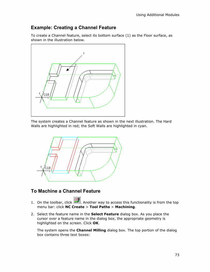
Using Additional Modules
73
Example: Creating a Channel Feature
To create a Channel feature, select its bottom surface (1) as the Floor surface, as
shown in the illustration below.
The system creates a Channel feature as shown in the next illustration. The Hard
Walls are highlighted in red; the Soft Walls are highlighted in cyan.
To Machine a Channel Feature
1. On the toolbar, click . Another way to access this functionality is from the top
menu bar: click NC Create > Tool Paths > Machining.
2. Select the feature name in the Select Feature dialog box. As you place the
cursor over a feature name in the dialog box, the appropriate geometry is
highlighted on the screen. Click OK.
The system opens the Channel Milling dialog box. The top portion of the dialog
box contains three text boxes:
Expert Machinist – Help Topic Collection
74
o Tool Path Name—The default name for the tool path file, such as
CHANNEL1_TP1 (the system uses the name of the feature for the first portion
of the tool path name). The system will use this file name for NC data
output. You can type a customized name. You can also click the Comments
button located under the Tool Path Name text box to type the Machine
Strategy Comments.
o Feature Name—The name of the feature being machined. This name is
displayed for information purposes only; you cannot change it. You can click
the Preview button located under the Feature Name text box to highlight
the feature geometry.
o Cutting Tool—The name of the cutting tool. When you use a Machine Tool
for the first time within the NC process, there is no active tool and the text
box displays None. For subsequent machining, the text box displays the
name of the active tool.
The middle portion of the Channel Milling dialog box contains the options for
defining the Machining Method, and the lower portion lists the machining Options.
At the bottom of the dialog box there are four buttons: OK, Cancel, Next, and
Play Path.
3. Change the cutting tool, if needed. You have to specify a tool name if there is no
active tool.
If the Machine Tool has preset cutting tools, select the tool you want by clicking
on the drop-down arrow and selecting the tool name from the drop-down list.
To access the Cutting Tool Manager, click next to the Cutting Tool text
box. This functionality lets you create new tools and modify existing ones.
Click Show Tool below the Cutting Tool text box to display the currently
selected tool in a pop-up window.
4. Define the Machining Method and Options, as needed, by selecting options and
typing values in the middle and lower portions of the dialog box. Click Play Path
at the bottom of the dialog box to display the currently defined tool path.
5. Click OK to complete machining the feature, Cancel to quit. If you want to use
the same settings to machine a similar feature, click Next.
The Channel Milling Dialog Box
The Machining Method section of the Channel Milling dialog box contains the
following options.
Roughing
Rough—Remove the material inside the Channel feature using rough milling and
leaving stock according to the Floor Stock and Wall Stock values:
• Floor Stock—Stock to be left on the Floor surfaces.
• Wall Stock—Stock to be left on the Hard Walls.

Using Additional Modules
75
Finishing
• Finish Floors—Finish mill the Floor surfaces. When you select this option, you
can use the Finish Passes button to set up the number of finish passes and the
depth increments.
• Back Off Walls—When you do rough milling and finish floors within the same
tool path, you can keep the tool off the walls by a specified additional distance
while the Floor is being finished. You can then finish the walls later. This option
becomes available when both the Rough and Finish Floors options are selected
and the Finish Walls option is cleared. When you select this option, type the
back-off distance in the text box to the right.
• Finish Walls—Finish mill the Hard Walls. When you select this option, you can
use the Finish Cuts button to set up the number of finish cuts and the depth
increments.
• Corners Only—Clean up the corners with a smaller tool after removing material
from the pocket with a large tool.
• Use CUTCOM—NC output will contain the CUTCOM statements. You can
customize their format and locations by clicking the Tool Path Properties
button and using the Cut Control tab of the Tool Path Properties dialog box.
Cut Motion
These options define the cut direction:
• One Direction—The tool cuts in one direction only, following the trajectory of
the Channel feature. At the end of each cut, the tool returns to the opposite side,
to start the next cut in the same direction.
• Back and Forth—The tool continuously machines the Channel feature, following
its trajectory and moving back and forth.
• Spiral—Generates a cutting path where the tool starts from one Soft Wall, cuts
down the center of the Channel, and then makes alternating cuts to the left and
to the right from the first cut. When necessary, the cuts follow the Hard Walls to
remove all the material inside the Channel feature. Use this option if the walls of
the Channel feature are not parallel, or if it has more than two Soft Walls.
These options define where material is relative to the tool rotation:
• Climb—The tool is to the left of material (assuming clockwise spindle rotation).
• Conventional—The tool is to the right of material (assuming clockwise spindle
rotation).
Connect Motions
These options describe the way the tool makes the horizontal connections between
the cutting motions:
• Clear Part—The tool clears the Soft Walls when exiting and entering the material
for each cut.
• Stay in Cut—The tool stays engaged in material between cuts.

Expert Machinist – Help Topic Collection
76
These options describe whether the tool retracts when connecting the cutting
motions:
• Stay Down—The tool does not retract between the cut motions.
• Retract—The tool retracts at the end of a cut motion and goes to the beginning
of the next cut motion at retract height (as defined by the Clearance tab of the
Tool Path Properties dialog box).
Start Wall
• Automatic—The Soft Wall where the tool starts cutting the material is chosen
automatically. Click next to the option to display the current Start Wall.
• Select—Select the Soft Wall where the tool starts cutting the material. Click
next to the option to select the Start Wall.
The Tool Path Properties button opens the Tool Path Properties dialog box,
which provides access to lower-level control of the tool path, such as spindle and
coolant statements, speeds, feeds, clearances, entry/exit, and cut control options.
The Options section of the Channel Milling dialog box contains the following option:
Use Fixture Offset—Allows you to store the fixture transformation offset in a
register on your machine. Type the Fixture Offset register value in the text box to
the right. If you use this option, NC output will contain the SET/OFSETL statements.
Example: Channel Machining
This example shows machining the Channel feature shown in the illustration below.
Select the following options in the Channel Milling dialog box:
• Rough
• Spiral
• Clear Part
• Stay Down
• Automatic

Using Additional Modules
77
The resulting tool path is shown in the next illustration. The tool starts from the
default Soft Wall, cuts down the center of the Channel, and then makes alternating
cuts to the left and to the right from the first cut. It traverses the Soft Walls and
does not retract between the cuts. When the tool reaches the widening of the
Channel, the cuts follow the Hard Walls to remove all the material inside the Channel
feature. When the tool encounters the third Soft Wall, it traverses this wall as well,
and does not retract between the cuts, according to the selected options.
Slot Features
To Create a Slot Feature
1. On the toolbar, click . Another way to access this functionality is from the top
menu bar: click NC Create > Features > Slot.
The Slot Feature dialog box opens with the following elements:
o Feature Name—The default feature name, such as Slot1 (the system
increments the number for the next Slot feature). You can type a
customized name.
o Define Feature Floor—Select the Floor surface for the feature.
o Adjust Feature Boundaries—Change the shape of the feature walls using
Sketcher. Use this option, for example, if you have two superimposed slots.
o Define Program Zero—Change the coordinate system used for feature
definition and machining.
o Adjust Soft Walls—Change Hard Walls to Soft and Soft Walls to Hard.
2. Select the Floor surface(s). On the SELECT SRFS menu, click Done/Return.
Expert Machinist – Help Topic Collection
78
3. Use the other elements, if needed. Click next to the element to display the
current setting. The Preview button lets you check the feature geometry by
highlighting the Hard Walls in red, Soft Walls in cyan.
4. Click OK to complete the feature, Cancel to quit.
To Machine a Slot Feature
1. On the toolbar, click . Another way to access this functionality is from the top
menu bar: click NC Create > Tool Paths > Machining.
2. Select the feature name in the Select Feature dialog box. As you place the
cursor over a feature name in the dialog box, the appropriate geometry is
highlighted on the screen. Click OK.
The system opens the Slot Milling dialog box. The top portion of the dialog box
contains three text boxes:
o Tool Path Name—The default name for the tool path file, such as
SLOT1_TP1 (the system uses the name of the feature for the first portion of
the tool path name). The system will use this file name for NC data output.
You can type a customized name. You can also click the Comments button
located under the Tool Path Name text box to type the Machine Strategy
Comments.
o Feature Name—The name of the feature being machined. This name is
displayed for information purposes only; you cannot change it. You can click
the Preview button located under the Feature Name text box to highlight
the feature geometry.
o Cutting Tool—The name of the cutting tool. When you use a Machine Tool
for the first time within the NC process, there is no active tool and the text
box displays None. For subsequent machining, the text box displays the
name of the active tool.
The middle portion of the Slot Milling dialog box contains the options for
defining the Machining Method and Options, and the lower, collapsible, portion
provides the options for Advanced Slot Milling. At the bottom of the dialog box
there are four buttons: OK, Cancel, Next, and Play Path.
3. Change the cutting tool, if needed. You have to specify a tool name if there is no
active tool.
If the Machine Tool has preset cutting tools, select the tool you want by clicking
on the drop-down arrow and selecting the tool name from the drop-down list.
To access the Cutting Tool Manager, click next to the Cutting Tool text
box. This functionality lets you create new tools and modify existing ones.
Click Show Tool below the Cutting Tool text box to display the currently
selected tool in a pop-up window.
Using Additional Modules
79
4. Define the Machining Method and Options, as needed, by selecting options and
typing values in the middle portion of the dialog box. The lower portion of the
dialog box contains the options for Advanced Slot Milling; use them if needed.
Click Play Path at the bottom of the dialog box to display the currently defined
tool path.
5. Click OK to complete machining the feature, Cancel to quit. If you want to use
the same settings to machine a similar feature, click Next.
The Slot Milling Dialog Box
The Machining Method section of the Slot Milling dialog box contains the following
options.
Roughing
Rough Slot—Remove the material inside the Slot feature using rough milling and
leaving stock on the Floor according to the Floor Stock value. Stock left on the Hard
Walls depends on the Advanced Slot Milling options selected.
Finishing
• Finish Floors—Finish mill the Floor surfaces. When you select this option, you
can use the Finish Passes button to set up the number of finish passes and the
depth increments.
• Finish Walls—Finish mill the Hard Walls. When you select this option, you can
use the Finish Cuts button to set up the number of finish cuts and the depth
increments.
• Use CUTCOM—NC output will contain the CUTCOM statements. You can
customize their format and locations by clicking the Tool Path Properties
button and using the Cut Control tab of the Tool Path Properties dialog box.
Cut Motion
These options define where material is relative to the tool rotation:
• Climb—The tool is to the left of material (assuming clockwise spindle rotation).
• Conventional—The tool is to the right of material (assuming clockwise spindle
rotation).
Top Entry
These options describe the way the tool enters the slot:
• Plunge—The tool enters the material vertically.
• Ramp—The tool enters at Ramp Angle to the x-axis of the Program Zero
coordinate system. You can customize the Ramp Angle by clicking the Tool
Path Properties button and using the Entry/Exit tab of the Tool Path
Properties dialog box.
• Helix—The tool enters along a helical path. You can customize the helical entry
by clicking the Tool Path Properties button and using the Entry/Exit tab of the
Tool Path Properties dialog box. Type the new values for the Helix Angle and
Expert Machinist – Help Topic Collection
80
the Radius of the helix (the default for which is calculated by the system based
on the size of the part).
• Entry Hole—The tool enters along a predefined entry hole. To use this option,
you must first create and machine an Entry Hole feature for this slot.
The Tool Path Properties button opens the Tool Path Properties dialog box,
which provides access to lower-level control of the tool path, such as spindle and
coolant statements, speeds, feeds, clearances, entry/exit, and cut control options.
Options
Use Fixture Offset—Allows you to store the fixture transformation offset in a
register on your machine. Type the Fixture Offset register value in the text box to
the right. If you use this option, NC output will contain the SET/OFSETL statements.
The Advanced Slot Milling section of the Slot Milling dialog box contains the
following options:
• Single Center Cut (default)—The tool performs a single cut along the center of
the slot. When you use this option, the amount of material left on the walls of the
slot depends on the difference between the width of the slot and the cutter
diameter of the tool.
• Multiple Cut—The tool performs multiple cuts to remove the material inside the
slot. Use the Wall Stock text box to specify the stock allowance left on the Hard
Walls of the slot. When you use this option, the following additional options
become available:
o One Direction—The tool cuts in one direction only. At the end of each cut,
the tool retracts and returns to the opposite side if the slot, to start the
next cut in the same direction.
o Back and Forth—The tool continuously machines the slot, moving back
and forth.
o Spiral—Generates a spiral cutting path.
Through Slot Features
To Create a Through Slot Feature
1. On the toolbar, click . Another way to access this functionality is from the top
menu bar: click NC Create > Features > Thru Slot.
The Through Slot Feature dialog box opens with the following elements:
o Feature Name—The default feature name, such as Thru_Slot1 (the
system increments the number for the next Through Slot feature). You can
type a customized name.
o Define Feature Walls— Select the side surfaces to be machined.
o Adjust Feature Boundaries—Change the shape of the feature walls using
Sketcher. Use this option, for example, if you have two superimposed slots.
Using Additional Modules
81
o Define Program Zero—Change the coordinate system used for feature
definition and machining.
o Adjust Soft Walls—Change Hard Walls to Soft and Soft Walls to Hard.
o Adjust Feature Bottom—Adjust the Floor depth of feature (by default, a
Through Slot extends all the way through the stock). To specify a different
Floor depth, select a surface, a datum plane, or type a value along the z-
axis of the feature-level Program Zero coordinate system.
2. Select the walls of the slot. Use the following commands on the SURF/LOOP
menu:
o Surface—Select the wall surfaces individually.
o Loop—Specify a closed loop of surfaces by selecting a face they surround.
If there is more than one loop of edges (for example, there is a hole in the
selected surface), you will be prompted to select an edge to use.
3. On the SURF/LOOP menu, click Done.
4. On the SELECT SRFS menu, click Done/Return.
5. Use the other elements, if needed. Click next to the element to display the
current setting. The Preview button lets you check the feature geometry by
highlighting the Hard Walls in red, Soft Walls in cyan.
6. Click OK to complete the feature, Cancel to quit.
To Machine a Through Slot Feature
1. On the toolbar, click . Another way to access this functionality is from the top
menu bar: click NC Create > Tool Paths > Machining.
2. Select the feature name in the Select Feature dialog box. As you place the
cursor over a feature name in the dialog box, the appropriate geometry is
highlighted on the screen. Click OK.
The system opens the Through Slot Milling dialog box. The top portion of the
dialog box contains three text boxes:
o Tool Path Name—The default name for the tool path file, such as
THRU_SLOT1_TP1 (the system uses the name of the feature for the first
portion of the tool path name). The system will use this file name for NC
data output. You can type a customized name. You can also click the
Comments button located under the Tool Path Name text box to type the
Machine Strategy Comments.
o Feature Name—The name of the feature being machined. This name is
displayed for information purposes only; you cannot change it. You can click
the Preview button located under the Feature Name text box to highlight
the feature geometry.

Expert Machinist – Help Topic Collection
82
o Cutting Tool—The name of the cutting tool. When you use a Machine Tool
for the first time within the NC process, there is no active tool and the text
box displays None. For subsequent machining, the text box displays the
name of the active tool.
The middle portion of the Through Slot Milling dialog box contains the options
for defining the Machining Method, and the lower portion lists the machining
Options. At the bottom of the dialog box there are four buttons: OK, Cancel,
Next, and Play Path.
3. Change the cutting tool, if needed. You have to specify a tool name if there is no
active tool.
If the Machine Tool has preset cutting tools, select the tool you want by clicking
on the drop-down arrow and selecting the tool name from the drop-down list.
To access the Cutting Tool Manager, click next to the Cutting Tool text
box. This functionality lets you create new tools and modify existing ones.
Click Show Tool below the Cutting Tool text box to display the currently
selected tool in a pop-up window.
4. Define the Machining Method and Options, as needed, by selecting options and
typing values in the middle and lower portions of the dialog box. Click Play Path
at the bottom of the dialog box to display the currently defined tool path.
5. Click OK to complete machining the feature, Cancel to quit. If you want to use
the same settings to machine a similar feature, click Next.
The Through Slot Milling Dialog Box
The Machining Method section of the Through Slot Milling dialog box contains the
following options.
Roughing
Rough Slot—Remove the material inside the Slot feature using rough milling.
Finishing
• Finish Walls—Finish mill the Hard Walls. When you select this option, you can
use the Finish Cuts button to set up the number of finish cuts and the depth
increments.
• Use CUTCOM—NC output will contain the CUTCOM statements. You can
customize their format and locations by clicking the Tool Path Properties
button and using the Cut Control tab of the Tool Path Properties dialog box.
This option becomes available only when you select the Finish Walls option
above.
Cut Motion
These options define where material is relative to the tool rotation:
• Climb—The tool is to the left of material (assuming clockwise spindle rotation).
Using Additional Modules
83
• Conventional—The tool is to the right of material (assuming clockwise spindle
rotation).
Start Position
This group of options can be used only if the Through Slot feature is completely
surrounded by Hard Walls. If the Through Slot feature contains a chain of Soft Walls
(there can only be one such chain), then the start position is determined
automatically based on the Soft Wall location and the Climb/Conventional setting.
If the Through Slot feature is completely surrounded by Hard Walls, then when you
select the Finish Walls option, the Start Position group of options becomes
available.
If the Use Default option is selected, the tool will start at a default position along
the through slot.
If you clear the Use Default checkbox, you can click next to it and select a
point anywhere on the edges surrounding the through slot. The tool will start at the
position closest to the selected point. Click to view the start position.
Top Entry
These options describe the way the tool enters the slot:
• Plunge—The tool enters the material vertically.
• Ramp—The tool enters at Ramp Angle to the x-axis of the Program Zero
coordinate system. You can customize the Ramp Angle by clicking the Tool
Path Properties button and using the Entry/Exit tab of the Tool Path
Properties dialog box.
• Helix—The tool enters along a helical path. You can customize the helical entry
by clicking the Tool Path Properties button and using the Entry/Exit tab of the
Tool Path Properties dialog box. Type the new values for the Helix Angle and
the Radius of the helix (the default for which is calculated by the system based
on the size of the tool).
• Entry Hole—The tool enters along a predefined entry hole. To use this option,
you must first create and machine an Entry Hole feature for this slot.
The Tool Path Properties button opens the Tool Path Properties dialog box,
which provides access to lower-level control of the tool path, such as spindle and
coolant statements, speeds, feeds, clearances, entry/exit, and cut control options.
Options
Use Fixture Offset—Allows you to store the fixture transformation offset in a
register on your machine. Type the Fixture Offset register value in the text box to
the right. If you use this option, NC output will contain the SET/OFSETL statements.

Expert Machinist – Help Topic Collection
84
Boss Top Features
To Create a Boss Top Feature
1. On the toolbar, click . Another way to access this functionality is from the top
menu bar: click NC Create > Features > Bosstop.
The Boss Top Feature dialog box opens with the following elements:
o Feature Name—The default feature name, such as Boss_Top1 (the system
increments the number for the next Boss Top feature). You can type a
customized name.
o Define Feature Floor—Select the Floor surface for the feature.
o Adjust Feature Boundaries—Change the shape of the feature walls using
Sketcher.
o Define Program Zero—Change the coordinate system used for feature
definition and machining.
o Adjust Soft Walls—Change Hard Walls to Soft and Soft Walls to Hard.
2. Select the Floor surface(s). On the SELECT SRFS menu, click Done/Return.
3. Use the other elements, if needed. Click next to the element to display the
current setting. The Preview button lets you check the feature geometry by
highlighting the Hard Walls in red, Soft Walls in cyan.
4. Click OK to complete the feature, Cancel to quit.
Example: Creating a Boss Top Feature
To machine the NC Model in this example, create a Step feature, and select the
bottom of the cavity (1) as the Floor surface, as shown in the following illustration.
Machining the Step feature leaves the material on top of the protruding boss.
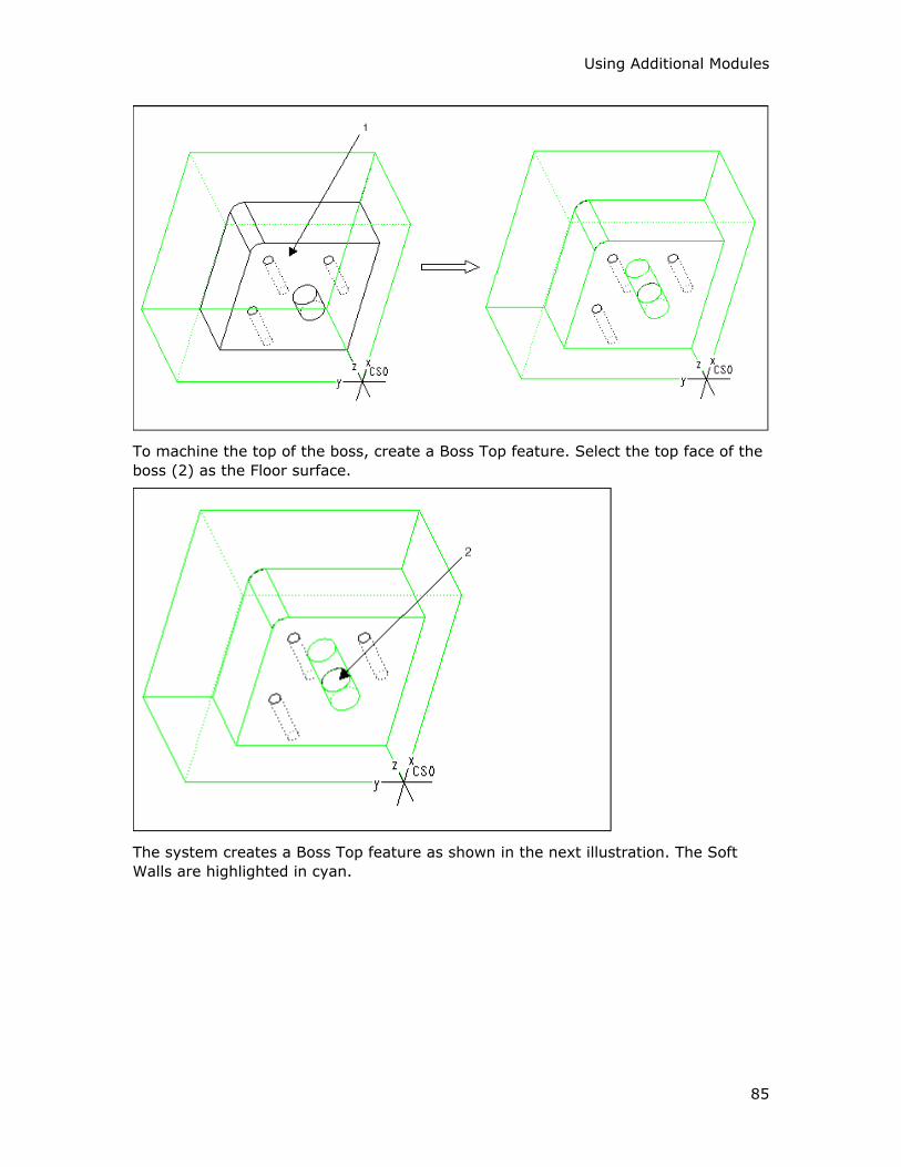
Using Additional Modules
85
To machine the top of the boss, create a Boss Top feature. Select the top face of the
boss (2) as the Floor surface.
The system creates a Boss Top feature as shown in the next illustration. The Soft
Walls are highlighted in cyan.
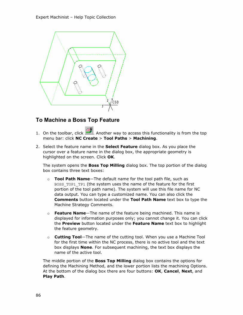
Expert Machinist – Help Topic Collection
86
To Machine a Boss Top Feature
1. On the toolbar, click . Another way to access this functionality is from the top
menu bar: click NC Create > Tool Paths > Machining.
2. Select the feature name in the Select Feature dialog box. As you place the
cursor over a feature name in the dialog box, the appropriate geometry is
highlighted on the screen. Click OK.
The system opens the Boss Top Milling dialog box. The top portion of the dialog
box contains three text boxes:
o Tool Path Name—The default name for the tool path file, such as
BOSS_TOP1_TP1 (the system uses the name of the feature for the first
portion of the tool path name). The system will use this file name for NC
data output. You can type a customized name. You can also click the
Comments button located under the Tool Path Name text box to type the
Machine Strategy Comments.
o Feature Name—The name of the feature being machined. This name is
displayed for information purposes only; you cannot change it. You can click
the Preview button located under the Feature Name text box to highlight
the feature geometry.
o Cutting Tool—The name of the cutting tool. When you use a Machine Tool
for the first time within the NC process, there is no active tool and the text
box displays None. For subsequent machining, the text box displays the
name of the active tool.
The middle portion of the Boss Top Milling dialog box contains the options for
defining the Machining Method, and the lower portion lists the machining Options.
At the bottom of the dialog box there are four buttons: OK, Cancel, Next, and
Play Path.
Using Additional Modules
87
3. Change the cutting tool, if needed. You have to specify a tool name if there is no
active tool.
If the Machine Tool has preset cutting tools, select the tool you want by clicking
on the drop-down arrow and selecting the tool name from the drop-down list.
To access the Cutting Tool Manager, click next to the Cutting Tool text
box. This functionality lets you create new tools and modify existing ones.
Click Show Tool below the Cutting Tool text box to display the currently
selected tool in a pop-up window.
4. Define the Machining Method and Options, as needed, by selecting options and
typing values in the middle and lower portions of the dialog box. Click Play Path
at the bottom of the dialog box to display the currently defined tool path.
5. Click OK to complete machining the feature, Cancel to quit. If you want to use
the same settings to machine a similar feature, click Next.
The Boss Top Milling Dialog Box
The Machining Method section of the Boss Top Milling dialog box contains the
following options.
Machining Mode
• Rough—Face down the boss top and leave stock according to the Rough to
value.
• Finish—Finish mill the boss top. When you select this option, you can use the
Finish Passes button to set up the number of finish passes and the depth
increments.
Cut Motion
These options define the cut direction:
• One Direction—The tool cuts in one direction only. At the end of each cut, the
tool returns to the opposite side, to start the next cut in the same direction.
• Back and Forth—The tool continuously machines the Face feature, moving back
and forth. At the end of a pass, it retracts and moves to the beginning of the next
pass, unless the Reverse Multiple Passes option is selected.
• Spiral—Generates a spiral cutting path.
These options define where material is relative to the tool rotation:
• Climb—The tool is to the left of material (assuming clockwise spindle rotation).
• Conventional—The tool is to the right of material (assuming clockwise spindle
rotation).
Cut Angle—Defines the angle between the cut direction and the x-axis of the
Program Zero coordinate system for One Direction and Back and Forth cut motion
types. The default is 0, which means that the tool cuts parallel to the x-axis of the
Expert Machinist – Help Topic Collection
88
Program Zero coordinate system. To change the cut direction, type the new value in
the Cut Angle text box.
Motion Between Cuts
These options describe the way the tool makes the horizontal connections between
the cutting motions:
• Clear Part—The tool clears the Soft Walls when exiting and entering the material
for each cut.
• Stay in Cut—The tool stays engaged in material between cuts.
• Clear Part on Last Cut—If Stay in Cut is selected, this option will make the
tool clear the part on the final cut of each pass.
These options describe whether the tool retracts when connecting the cutting
motions:
• Stay Down—The tool does not retract between the cut motions.
• Retract—The tool retracts at the end of a cut motion and goes to the beginning
of the next cut motion at retract height (as defined by the Clearance tab of the
Tool Path Properties dialog box).
The Tool Path Properties button opens the Tool Path Properties dialog box,
which provides access to lower-level control of the tool path, such as spindle and
coolant statements, speeds, feeds, clearances, entry/exit, and cut control options.
The Options section of the Boss Top Milling dialog box contains the following
options:
• Reverse Multiple Passes—If Back and Forth is selected, this option will
reverse the Cut Angle on successive passes. Use this option to perform
continuous back and forth machining between passes.
• Use Fixture Offset—Allows you to store the fixture transformation offset in a
register on your machine. Type the Fixture Offset register value in the text box to
the right. If you use this option, NC output will contain the SET/OFSETL
statements.
Example: Boss Top Machining
This example shows machining the Boss Top feature shown in the illustration below.
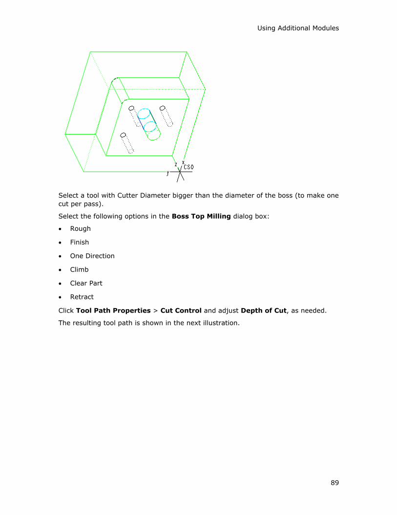
Using Additional Modules
89
Select a tool with Cutter Diameter bigger than the diameter of the boss (to make one
cut per pass).
Select the following options in the Boss Top Milling dialog box:
• Rough
• Finish
• One Direction
• Climb
• Clear Part
• Retract
Click Tool Path Properties > Cut Control and adjust Depth of Cut, as needed.
The resulting tool path is shown in the next illustration.

Expert Machinist – Help Topic Collection
90
Flange Features
To Create a Flange Feature
1. On the toolbar, click . Another way to access this functionality is from the top
menu bar: click NC Create > Features > Flange.
The Flange Feature dialog box opens with the following elements:
o Feature Name—The default feature name, such as Flange1 (the system
increments the number for the next Flange feature). You can type a
customized name.
o Define Feature Floor—Select the Floor surface for the feature.
o Adjust Feature Boundaries—Change the shape of the feature walls using
Sketcher.
o Define Program Zero—Change the coordinate system used for feature
definition and machining.
o Adjust Soft Walls—Change Hard Walls to Soft and Soft Walls to Hard.
2. Select the Floor surface(s). On the SELECT SRFS menu, click Done/Return.
3. Use the other elements, if needed. Click next to the element to display the
current setting. The Preview button lets you check the feature geometry by
highlighting the Hard Walls in red, Soft Walls in cyan.
4. Click OK to complete the feature, Cancel to quit.
Example: Creating a Flange Feature
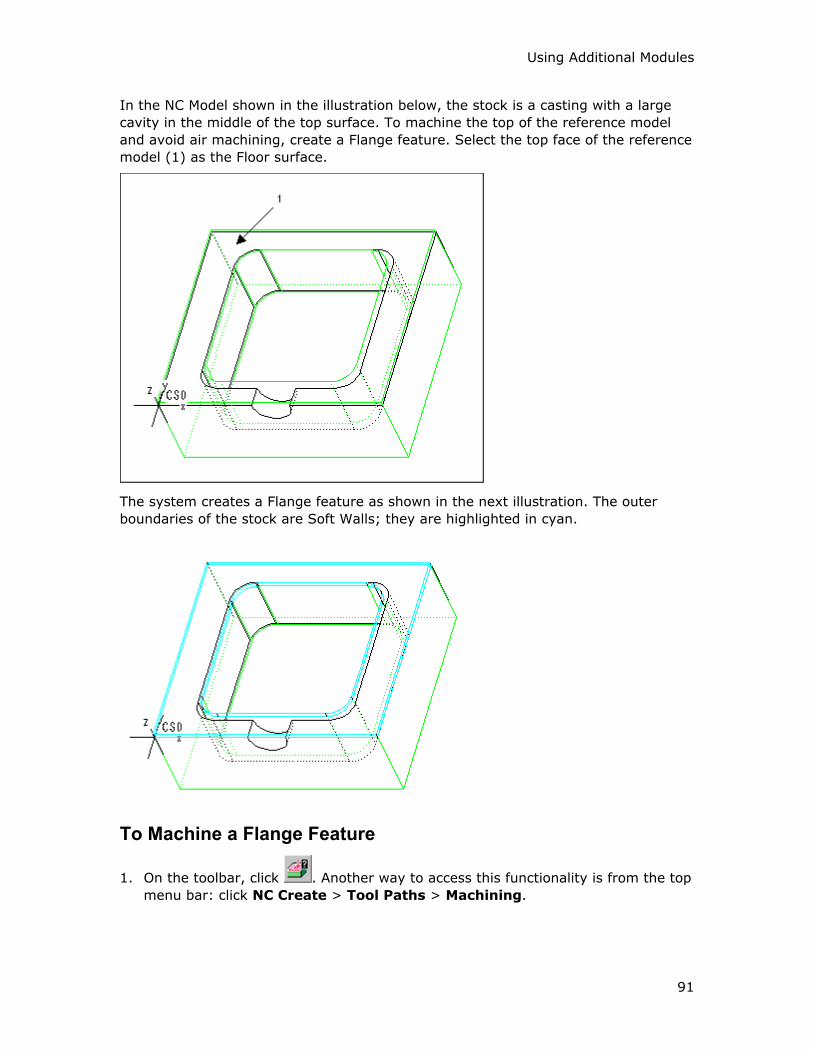
Using Additional Modules
91
In the NC Model shown in the illustration below, the stock is a casting with a large
cavity in the middle of the top surface. To machine the top of the reference model
and avoid air machining, create a Flange feature. Select the top face of the reference
model (1) as the Floor surface.
The system creates a Flange feature as shown in the next illustration. The outer
boundaries of the stock are Soft Walls; they are highlighted in cyan.
To Machine a Flange Feature
1. On the toolbar, click . Another way to access this functionality is from the top
menu bar: click NC Create > Tool Paths > Machining.
Expert Machinist – Help Topic Collection
92
2. Select the feature name in the Select Feature dialog box. As you place the
cursor over a feature name in the dialog box, the appropriate geometry is
highlighted on the screen. Click OK.
The system opens the Flange Milling dialog box. The top portion of the dialog
box contains three text boxes:
o Tool Path Name—The default name for the tool path file, such as
FLANGE1_TP1 (the system uses the name of the feature for the first portion
of the tool path name). The system will use this file name for NC data
output. You can type a customized name. You can also click the Comments
button located under the Tool Path Name text box to type the Machine
Strategy Comments.
o Feature Name—The name of the feature being machined. This name is
displayed for information purposes only; you cannot change it. You can click
the Preview button located under the Feature Name text box to highlight
the feature geometry.
o Cutting Tool—The name of the cutting tool. When you use a Machine Tool
for the first time within the NC process, there is no active tool and the text
box displays None. For subsequent machining, the text box displays the
name of the active tool.
The middle portion of the Flange Milling dialog box contains the options for
defining the Machining Method, and the lower portion lists the machining Options.
At the bottom of the dialog box there are four buttons: OK, Cancel, Next, and
Play Path.
3. Change the cutting tool, if needed. You have to specify a tool name if there is no
active tool.
If the Machine Tool has preset cutting tools, select the tool you want by clicking
on the drop-down arrow and selecting the tool name from the drop-down list.
To access the Cutting Tool Manager, click next to the Cutting Tool text
box. This functionality lets you create new tools and modify existing ones.
Click Show Tool below the Cutting Tool text box to display the currently
selected tool in a pop-up window.
4. Define the Machining Method and Options, as needed, by selecting options and
typing values in the middle and lower portions of the dialog box. Click Play Path
at the bottom of the dialog box to display the currently defined tool path.
5. Click OK to complete machining the feature, Cancel to quit. If you want to use
the same settings to machine a similar feature, click Next.
The Flange Milling Dialog Box
The Machining Method section of the Flange Milling dialog box contains the
following options.

Using Additional Modules
93
Roughing
Rough Flange—Remove the material inside the Flange feature using rough milling
and leaving stock according to the Floor Stock and Wall Stock values:
• Floor Stock—Stock to be left on the Floor surfaces.
• Wall Stock—Stock to be left on the Hard Walls. If the Flange feature does not
have Hard Walls, this text box will be unavailable.
Finishing
• Finish Floors—Finish mill the Floor surfaces. When you select this option, you
can use the Finish Passes button to set up the number of finish passes and the
depth increments.
• Finish Walls—Finish mill the Hard Walls. When you select this option, you can
use the Finish Cuts button to set up the number of finish cuts and the depth
increments. If the Flange feature does not have Hard Walls, this option and the
Finish Cuts button will be unavailable.
• Use CUTCOM—NC output will contain the CUTCOM statements. You can
customize their format and locations by clicking the Tool Path Properties
button and using the Cut Control tab of the Tool Path Properties dialog box.
Cut Motion
These options define the cut motion pattern:
• Follow Outer Contour—The tool follows the outer contour of the Flange.
• Follow Inner Contour—The tool follows the inner contour of the Flange.
These options define where material is relative to the tool rotation:
• Climb—The tool is to the left of material (assuming clockwise spindle rotation).
• Conventional—The tool is to the right of material (assuming clockwise spindle
rotation).
Start Location
These options describe where the tool starts cutting:
• Start From Outer Contour—The tool starts at the outer contour of the Flange
and moves inward.
• Start From Inner Contour—The tool starts at the inner contour of the Flange
and moves outward. This option is not available if the inner contour is comprised
of Hard Walls.
The Tool Path Properties button opens the Tool Path Properties dialog box,
which provides access to lower-level control of the tool path, such as spindle and
coolant statements, speeds, feeds, clearances, entry/exit, and cut control options.
The Options section of the Flange Milling dialog box contains the following option:
Expert Machinist – Help Topic Collection
94
Use Fixture Offset—Allows you to store the fixture transformation offset in a
register on your machine. Type the Fixture Offset register value in the text box to
the right. If you use this option, NC output will contain the SET/OFSETL statements.
O-Ring Features
To Create an O-Ring Feature
1. On the toolbar, click . Another way to access this functionality is from the top
menu bar: click NC Create > Features > O-Ring.
The O-Ring Feature dialog box opens with the following elements:
o Feature Name—The default feature name, such as O-Ring1 (the system
increments the number for the next O-Ring feature). You can type a
customized name.
o Define Feature Floor—Select the Floor surface for the feature.
o Adjust Feature Boundaries—Change the shape of the feature walls using
Sketcher.
o Define Program Zero—Change the coordinate system used for feature
definition and machining.
o Adjust Soft Walls—Change Hard Walls to Soft and Soft Walls to Hard.
2. Select the Floor surface(s). On the SELECT SRFS menu, click Done/Return.
3. Use the other elements, if needed. Click next to the element to display the
current setting. The Preview button lets you check the feature geometry by
highlighting the Hard Walls in red.
4. Click OK to complete the feature, Cancel to quit.
To Machine an O-Ring Feature
1. On the toolbar, click . Another way to access this functionality is from the top
menu bar: click NC Create > Tool Paths > Machining.
2. Select the feature name in the Select Feature dialog box. As you place the
cursor over a feature name in the dialog box, the appropriate geometry is
highlighted on the screen. Click OK.
The system opens the O-Ring Milling dialog box. The top portion of the dialog
box contains three text boxes:
o Tool Path Name—The default name for the tool path file, such as O-
RING1_TP1 (the system uses the name of the feature for the first portion of
the tool path name). The system will use this file name for NC data output.
You can type a customized name. You can also click the Comments button
Using Additional Modules
95
located under the Tool Path Name text box to type the Machine Strategy
Comments.
o Feature Name—The name of the feature being machined. This name is
displayed for information purposes only; you cannot change it. You can click
the Preview button located under the Feature Name text box to highlight
the feature geometry.
o Cutting Tool—The name of the cutting tool. When you use a Machine Tool
for the first time within the NC process, there is no active tool and the text
box displays None. For subsequent machining, the text box displays the
name of the active tool.
The middle portion of the O-Ring Milling dialog box contains the options for
defining the Machining Method, and the lower portion lists the machining Options.
At the bottom of the dialog box there are four buttons: OK, Cancel, Next, and
Play Path.
3. Change the cutting tool, if needed. You have to specify a tool name if there is no
active tool.
If the Machine Tool has preset cutting tools, select the tool you want by clicking
on the drop-down arrow and selecting the tool name from the drop-down list.
To access the Cutting Tool Manager, click next to the Cutting Tool text
box. This functionality lets you create new tools and modify existing ones.
Click Show Tool below the Cutting Tool text box to display the currently
selected tool in a pop-up window.
4. Define the Machining Method and Options, as needed, by selecting options and
typing values in the middle and lower portions of the dialog box. Click Play Path
at the bottom of the dialog box to display the currently defined tool path.
5. Click OK to complete machining the feature, Cancel to quit. If you want to use
the same settings to machine a similar feature, click Next.
The O-Ring Milling Dialog Box
The Machining Method section of the O-Ring Milling dialog box contains the
following options.
Roughing
Rough Groove—Remove the material inside the O-Ring feature using rough milling
and leaving stock on the Floor according to the Floor Stock value.
Finishing
• Finish Floors—Finish mill the Floor surfaces. When you select this option, you
can use the Finish Passes button to set up the number of finish passes and the
depth increments.
Expert Machinist – Help Topic Collection
96
• Finish Walls—Finish mill the Hard Walls. When you select this option, you can
use the Finish Cuts button to set up the number of finish cuts and the depth
increments.
• Use CUTCOM—NC output will contain the CUTCOM statements. You can
customize their format and locations by clicking the Tool Path Properties
button and using the Cut Control tab of the Tool Path Properties dialog box.
This option becomes available only when you select the Finish Walls option
above.
Cut Motion
These options define where material is relative to the tool rotation:
• Climb—The tool is to the left of material (assuming clockwise spindle rotation).
• Conventional—The tool is to the right of material (assuming clockwise spindle
rotation).
Start Position
If the Use Default option is selected, the tool will start at a default position along
the closed groove.
If you clear the Use Default checkbox, you can click next to it and select a
point anywhere on the edges surrounding the closed groove. The tool will start at the
position closest to the selected point. Click to view the start position.
Top Entry
These options describe the way the tool enters the groove:
• Plunge—The tool enters the material vertically.
• Ramp—The tool enters at Ramp Angle to the x-axis of the Program Zero
coordinate system. You can customize the Ramp Angle by clicking the Tool
Path Properties button and using the Entry/Exit tab of the Tool Path
Properties dialog box.
• Entry Hole—The tool enters along a predefined entry hole. To use this option,
you must first create and machine an Entry Hole feature.
The Tool Path Properties button opens the Tool Path Properties dialog box,
which provides access to lower-level control of the tool path, such as spindle and
coolant statements, speeds, feeds, clearances, entry/exit, and cut control options.
The Options section of the O-Ring Milling dialog box contains the following option:
Use Fixture Offset—Allows you to store the fixture transformation offset in a
register on your machine. Type the Fixture Offset register value in the text box to
the right. If you use this option, NC output will contain the SET/OFSETL statements.
Example: O-Ring Machining
This example shows machining the O-Ring feature shown in the illustration below. To
create the O-Ring feature, select the bottom of the groove (1) as the Floor surface.
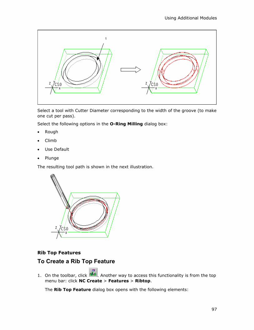
Using Additional Modules
97
Select a tool with Cutter Diameter corresponding to the width of the groove (to make
one cut per pass).
Select the following options in the O-Ring Milling dialog box:
• Rough
• Climb
• Use Default
• Plunge
The resulting tool path is shown in the next illustration.
Rib Top Features
To Create a Rib Top Feature
1. On the toolbar, click . Another way to access this functionality is from the top
menu bar: click NC Create > Features > Ribtop.
The Rib Top Feature dialog box opens with the following elements:
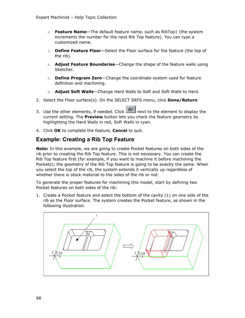
Expert Machinist – Help Topic Collection
98
o Feature Name—The default feature name, such as RibTop1 (the system
increments the number for the next Rib Top feature). You can type a
customized name.
o Define Feature Floor—Select the Floor surface for the feature (the top of
the rib).
o Adjust Feature Boundaries—Change the shape of the feature walls using
Sketcher.
o Define Program Zero—Change the coordinate system used for feature
definition and machining.
o Adjust Soft Walls—Change Hard Walls to Soft and Soft Walls to Hard.
2. Select the Floor surface(s). On the SELECT SRFS menu, click Done/Return.
3. Use the other elements, if needed. Click next to the element to display the
current setting. The Preview button lets you check the feature geometry by
highlighting the Hard Walls in red, Soft Walls in cyan.
4. Click OK to complete the feature, Cancel to quit.
Example: Creating a Rib Top Feature
Note: In this example, we are going to create Pocket features on both sides of the
rib prior to creating the Rib Top feature. This is not necessary. You can create the
Rib Top feature first (for example, if you want to machine it before machining the
Pockets); the geometry of the Rib Top feature is going to be exactly the same. When
you select the top of the rib, the system extends it vertically up regardless of
whether there is stock material to the sides of the rib or not.
To generate the proper features for machining this model, start by defining two
Pocket features on both sides of the rib:
1. Create a Pocket feature and select the bottom of the cavity (1) on one side of the
rib as the Floor surface. The system creates the Pocket feature, as shown in the
following illustration.
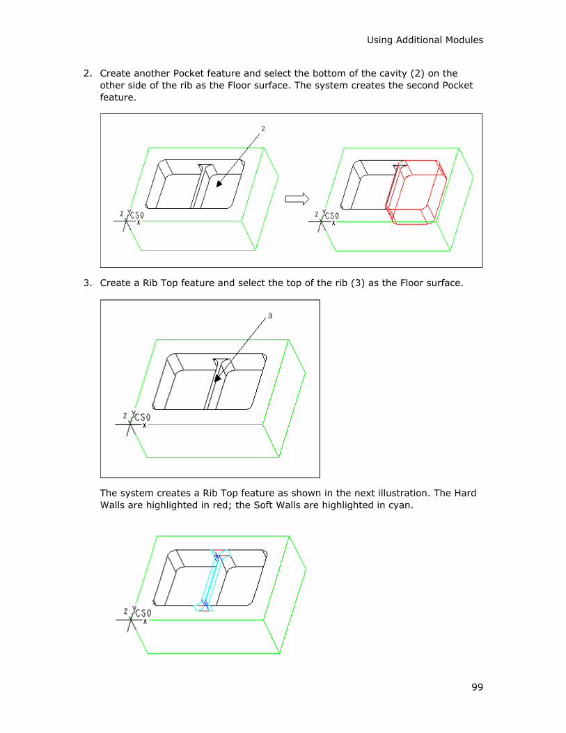
Using Additional Modules
99
2. Create another Pocket feature and select the bottom of the cavity (2) on the
other side of the rib as the Floor surface. The system creates the second Pocket
feature.
3. Create a Rib Top feature and select the top of the rib (3) as the Floor surface.
The system creates a Rib Top feature as shown in the next illustration. The Hard
Walls are highlighted in red; the Soft Walls are highlighted in cyan.
Expert Machinist – Help Topic Collection
100
To Machine a Rib Top Feature
1. On the toolbar, click . Another way to access this functionality is from the top
menu bar: click NC Create > Tool Paths > Machining.
2. Select the feature name in the Select Feature dialog box. As you place the
cursor over a feature name in the dialog box, the appropriate geometry is
highlighted on the screen. Click OK.
The system opens the Rib Top Milling dialog box. The top portion of the dialog
box contains three text boxes:
o Tool Path Name—The default name for the tool path file, such as
RIBTOP1_TP1 (the system uses the name of the feature for the first portion
of the tool path name). The system will use this file name for NC data
output. You can type a customized name. You can also click the Comments
button located under the Tool Path Name text box to type the Machine
Strategy Comments.
o Feature Name—The name of the feature being machined. This name is
displayed for information purposes only; you cannot change it. You can click
the Preview button located under the Feature Name text box to highlight
the feature geometry.
o Cutting Tool—The name of the cutting tool. When you use a Machine Tool
for the first time within the NC process, there is no active tool and the text
box displays None. For subsequent machining, the text box displays the
name of the active tool.
The middle portion of the Rib Top Milling dialog box contains the options for
defining the Machining Method, and the lower portion lists the machining Options.
At the bottom of the dialog box there are four buttons: OK, Cancel, Next, and
Play Path.
3. Change the cutting tool, if needed. You have to specify a tool name if there is no
active tool.
If the Machine Tool has preset cutting tools, select the tool you want by clicking
on the drop-down arrow and selecting the tool name from the drop-down list.
To access the Cutting Tool Manager, click next to the Cutting Tool text
box. This functionality lets you create new tools and modify existing ones.
Click Show Tool below the Cutting Tool text box to display the currently
selected tool in a pop-up window.
4. Define the Machining Method and Options, as needed, by selecting options and
typing values in the middle and lower portions of the dialog box. Click Play Path
at the bottom of the dialog box to display the currently defined tool path.
5. Click OK to complete machining the feature, Cancel to quit. If you want to use
the same settings to machine a similar feature, click Next.

Using Additional Modules
101
The Rib Top Milling Dialog Box
The Machining Method section of the Rib Top Milling dialog box contains the
following options.
Roughing
Rough Rib Top—Remove the material from the top of the rib using rough milling
and leaving stock according to the Floor Stock and Wall Stock values:
• Floor Stock—Stock to be left on the Floor surfaces.
• Wall Stock—Stock to be left on the Hard Walls.
Finishing
• Finish Floors—Finish mill the Floor surfaces. When you select this option, you
can use the Finish Passes button to set up the number of finish passes and the
depth increments.
• Back Off Walls—When you do rough milling and finish floors within the same
tool path, you can keep the tool off the walls by a specified additional distance
while the Floor is being finished. You can then finish the walls later. This option
becomes available when both the Rough and Finish Floors options are selected
and the Finish Walls option is cleared. When you select this option, type the
back-off distance in the text box to the right.
• Finish Walls—Finish mill the Hard Walls. When you select this option, you can
use the Finish Cuts button to set up the number of finish cuts and the depth
increments.
• Use CUTCOM—NC output will contain the CUTCOM statements. You can
customize their format and locations by clicking the Tool Path Properties
button and using the Cut Control tab of the Tool Path Properties dialog box.
Cut Motion
These options define where material is relative to the tool rotation:
• Climb—The tool is to the left of material (assuming clockwise spindle rotation).
• Conventional—The tool is to the right of material (assuming clockwise spindle
rotation).
Entry Wall
• Automatic—The Soft Wall where the tool starts cutting the material is chosen
automatically. Click next to the option to display the current Entry Wall.
• Select—Select the Soft Wall where the tool starts cutting the material. Click
next to the option to select the Entry Wall.
Expert Machinist – Help Topic Collection
102
Rib Start Wall
If the Rib Top feature has an open configuration, you can use the following options to
specify which Soft Wall is opposite the Hard Wall of the rib, and thus define the
direction of machining the rib:
• Automatic—The Soft Wall defining the machining direction is chosen
automatically. Click next to the option to display the current Rib Start Wall.
• Select—Select Soft Wall that is opposite the Hard Wall of the rib to define the
machining direction. Click next to the option to select the Rib Start Wall.
Top Entry
These options describe the way the tool enters the material:
• Plunge—The tool enters the material vertically.
• Ramp—The tool enters at Ramp Angle to the x-axis of the Program Zero
coordinate system. You can customize the Ramp Angle by clicking the Tool
Path Properties button and using the Entry/Exit tab of the Tool Path
Properties dialog box.
• Helix—The tool enters along a helical path. You can customize the helical entry
by clicking the Tool Path Properties button and using the Entry/Exit tab of the
Tool Path Properties dialog box. Type the new values for the Helix Angle and
the Radius of the helix (the default for which is calculated by the system based
on the size of the part).
• Entry Hole—The tool enters along a predefined entry hole. To use this option,
you must first create and machine an Entry Hole feature.
The Tool Path Properties button opens the Tool Path Properties dialog box,
which provides access to lower-level control of the tool path, such as spindle and
coolant statements, speeds, feeds, clearances, entry/exit, and cut control options.
The Options section of the Rib Top Milling dialog box contains the following option:
Use Fixture Offset—Allows you to store the fixture transformation offset in a
register on your machine. Type the Fixture Offset register value in the text box to
the right. If you use this option, NC output will contain the SET/OFSETL statements.
Example: Rib Top Machining
To machine the model in this example, start with machining the two Pocket features
on either side of the rib (as shown in the following illustration), and then machine
the Rib Top feature.
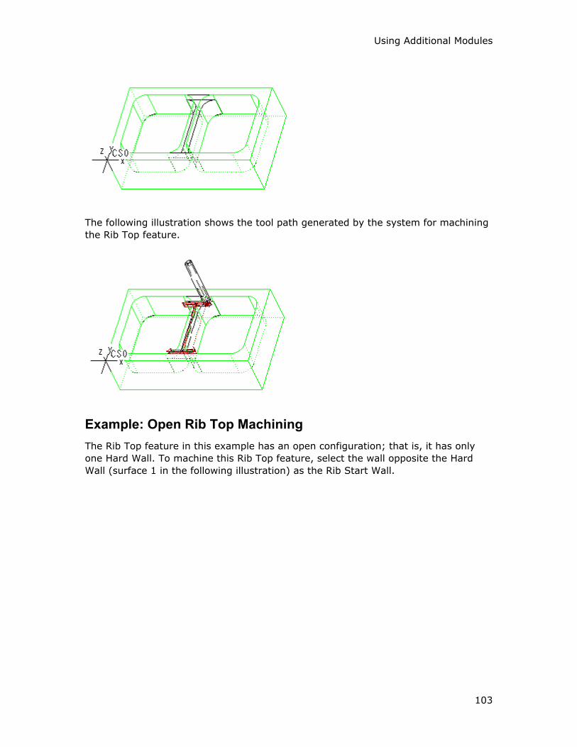
Using Additional Modules
103
The following illustration shows the tool path generated by the system for machining
the Rib Top feature.
Example: Open Rib Top Machining
The Rib Top feature in this example has an open configuration; that is, it has only
one Hard Wall. To machine this Rib Top feature, select the wall opposite the Hard
Wall (surface 1 in the following illustration) as the Rib Start Wall.
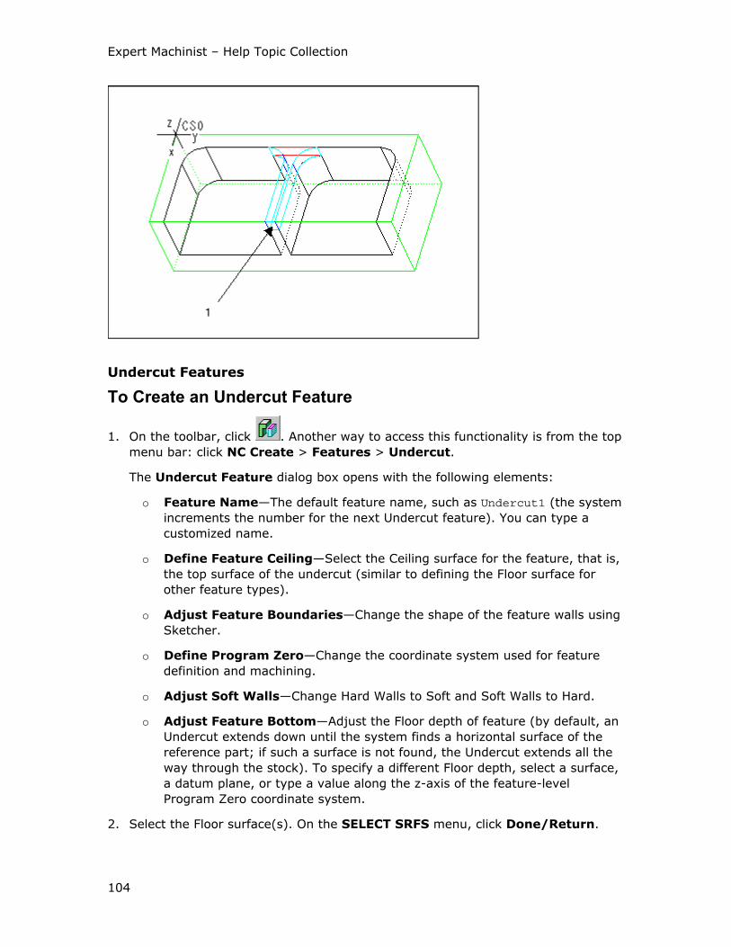
Expert Machinist – Help Topic Collection
104
Undercut Features
To Create an Undercut Feature
1. On the toolbar, click . Another way to access this functionality is from the top
menu bar: click NC Create > Features > Undercut.
The Undercut Feature dialog box opens with the following elements:
o Feature Name—The default feature name, such as Undercut1 (the system
increments the number for the next Undercut feature). You can type a
customized name.
o Define Feature Ceiling—Select the Ceiling surface for the feature, that is,
the top surface of the undercut (similar to defining the Floor surface for
other feature types).
o Adjust Feature Boundaries—Change the shape of the feature walls using
Sketcher.
o Define Program Zero—Change the coordinate system used for feature
definition and machining.
o Adjust Soft Walls—Change Hard Walls to Soft and Soft Walls to Hard.
o Adjust Feature Bottom—Adjust the Floor depth of feature (by default, an
Undercut extends down until the system finds a horizontal surface of the
reference part; if such a surface is not found, the Undercut extends all the
way through the stock). To specify a different Floor depth, select a surface,
a datum plane, or type a value along the z-axis of the feature-level
Program Zero coordinate system.
2. Select the Floor surface(s). On the SELECT SRFS menu, click Done/Return.
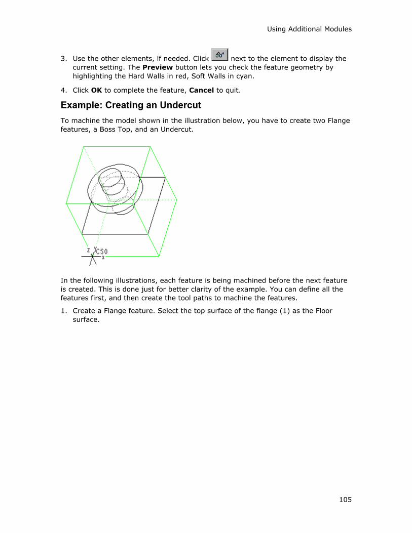
Using Additional Modules
105
3. Use the other elements, if needed. Click next to the element to display the
current setting. The Preview button lets you check the feature geometry by
highlighting the Hard Walls in red, Soft Walls in cyan.
4. Click OK to complete the feature, Cancel to quit.
Example: Creating an Undercut
To machine the model shown in the illustration below, you have to create two Flange
features, a Boss Top, and an Undercut.
In the following illustrations, each feature is being machined before the next feature
is created. This is done just for better clarity of the example. You can define all the
features first, and then create the tool paths to machine the features.
1. Create a Flange feature. Select the top surface of the flange (1) as the Floor
surface.
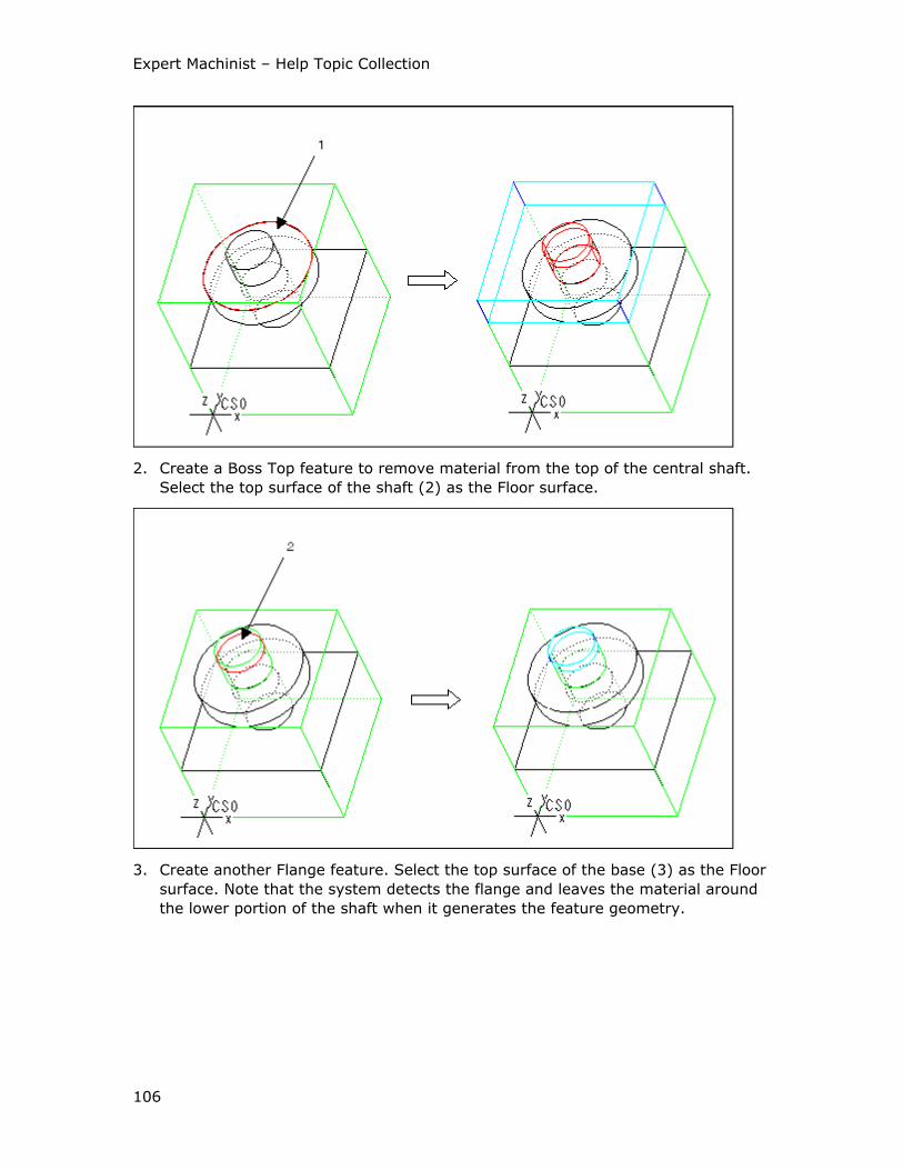
Expert Machinist – Help Topic Collection
106
2. Create a Boss Top feature to remove material from the top of the central shaft.
Select the top surface of the shaft (2) as the Floor surface.
3. Create another Flange feature. Select the top surface of the base (3) as the Floor
surface. Note that the system detects the flange and leaves the material around
the lower portion of the shaft when it generates the feature geometry.
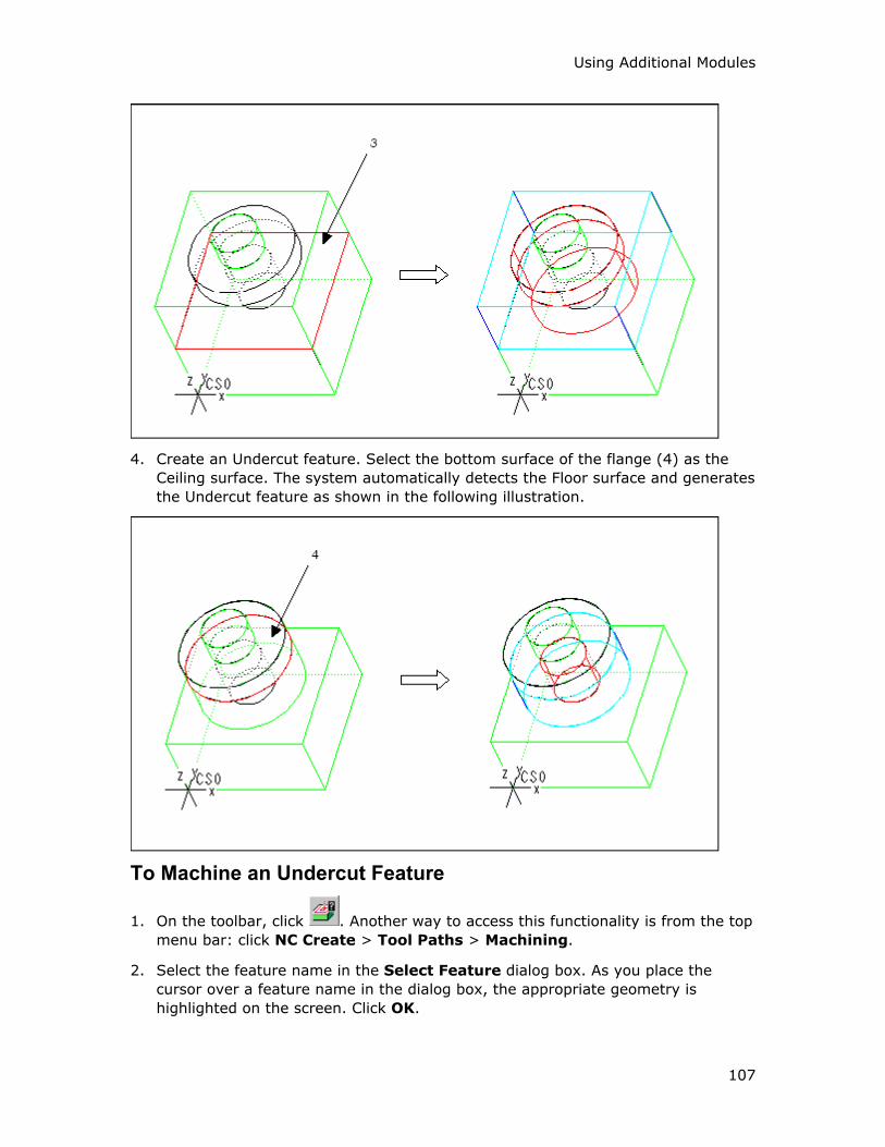
Using Additional Modules
107
4. Create an Undercut feature. Select the bottom surface of the flange (4) as the
Ceiling surface. The system automatically detects the Floor surface and generates
the Undercut feature as shown in the following illustration.
To Machine an Undercut Feature
1. On the toolbar, click . Another way to access this functionality is from the top
menu bar: click NC Create > Tool Paths > Machining.
2. Select the feature name in the Select Feature dialog box. As you place the
cursor over a feature name in the dialog box, the appropriate geometry is
highlighted on the screen. Click OK.
Expert Machinist – Help Topic Collection
108
The system opens the Undercut Milling dialog box. The top portion of the dialog
box contains three text boxes:
o Tool Path Name—The default name for the tool path file, such as
UNDERCUT1_TP1 (the system uses the name of the feature for the first
portion of the tool path name). The system will use this file name for NC
data output. You can type a customized name. You can also click the
Comments button located under the Tool Path Name text box to type the
Machine Strategy Comments.
o Feature Name—The name of the feature being machined. This name is
displayed for information purposes only; you cannot change it. You can click
the Preview button located under the Feature Name text box to highlight
the feature geometry.
o Cutting Tool—The name of the cutting tool. When you use a Machine Tool
for the first time within the NC process, there is no active tool and the text
box displays None. For subsequent machining, the text box displays the
name of the active tool.
The middle portion of the Undercut Milling dialog box contains the options for
defining the Machining Strategy, and the lower portion lists the machining
Options. At the bottom of the dialog box there are four buttons: OK, Cancel,
Next, and Play Path.
3. Change the cutting tool, if needed. You have to use a tool of the type Side Mill.
If the Machine Tool has preset cutting tools, select the tool you want by clicking
on the drop-down arrow and selecting the tool name from the drop-down list.
To access the Cutting Tool Manager, click next to the Cutting Tool text
box. This functionality lets you create new tools and modify existing ones.
Click Show Tool below the Cutting Tool text box to display the currently
selected tool in a pop-up window.
4. Define the Machining Strategy and Options, as needed, by selecting options and
typing values in the middle and lower portions of the dialog box. Click Play Path
at the bottom of the dialog box to display the currently defined tool path.
5. Click OK to complete machining the feature, Cancel to quit. If you want to use
the same settings to machine a similar feature, click Next.
The Undercut Milling Dialog Box
The Machining Strategy section of the Undercut Milling dialog box contains the
following options.
Roughing
Rough Undercut—Remove the material inside the Undercut feature using rough
milling and leaving stock according to the Ceiling/Floor Stock and Wall Stock
values:
Using Additional Modules
109
• Ceiling/Floor Stock—Stock to be left on the Ceiling and Floor surfaces.
• Wall Stock—Stock to be left on the Hard Walls.
These options define the number of cutting passes:
• Multiple Cuts—The tool makes multiple cutting passes, machining away all the
material and leaving stock on the Ceiling and Floor surfaces according to the
Ceiling/Floor Stock value. The first cutting pass is at the top of the Undercut
(taking into account the Cutter Width of the tool and the ceiling stock value). You
can control the distance between the passes by using the Depth of Cut option,
located on the Cut Control tabbed page of the Tool Path Properties dialog
box.
• Single Center Cut—The tool makes only one cutting pass, leaving equal
amounts of material on the Ceiling and Floor surfaces. If you select this option,
the Ceiling/Floor Stock text box becomes unavailable, because the amount of
stock left on the Ceiling and Floor surfaces is determined by the Cutter Width
parameter of the tool.
Finishing
• Finish Ceiling/Floor—Finish mill the Ceiling and Floor surfaces. When you select
this option, you can use the Finish Passes button to set up the number of finish
passes and the depth increments.
• Finish Walls—Finish mill the Hard Walls. When you select this option, you can
use the Finish Cuts button to set up the number of finish cuts and the depth
increments.
• Use CUTCOM—NC output will contain the CUTCOM statements. You can
customize their format and locations by clicking the Tool Path Properties
button and using the Cut Control tab of the Tool Path Properties dialog box.
Cut Motion
These options define the cut direction:
• One Direction—The tool cuts in one direction only. At the end of each cut, the
tool returns to the opposite side, to start the next cut in the same direction.
• Back and Forth—The tool continuously machines the Undercut, moving back
and forth.
These options define where material is relative to the tool rotation:
• Climb—The tool is to the left of material (assuming clockwise spindle rotation).
• Conventional—The tool is to the right of material (assuming clockwise spindle
rotation).
Motion Between Cuts
These options describe the way the tool makes the horizontal connections between
the cutting motions:
Expert Machinist – Help Topic Collection
110
• Clear Part—The tool clears the Soft Walls when exiting and entering the material
for each cut.
• Stay in Cut—The tool stays engaged in material between cuts.
These options describe whether the tool retracts when connecting the cutting
motions:
• Stay Down—The tool does not retract between the cut motions.
• Retract—The tool retracts at the end of a cut motion and goes to the beginning
of the next cut motion at retract height (as defined by the Clearance tab of the
Tool Path Properties dialog box).
The Tool Path Properties button opens the Tool Path Properties dialog box,
which provides access to lower-level control of the tool path, such as spindle and
coolant statements, speeds, feeds, clearances, entry/exit, and cut control options.
The Options section of the Undercut Milling dialog box contains the following
option:
Use Fixture Offset—Allows you to store the fixture transformation offset in a
register on your machine. Type the Fixture Offset register value in the text box to
the right. If you use this option, NC output will contain the SET/OFSETL statements.
Using the Side Mill Tool
To machine an Undercut feature, you have to use a tool of the type Side Milling.
The parameters of a Side Milling tool (as shown in the following illustration) are:
1. Cutter Diameter
2. Length
3. Corner Radius
4. Cutter Width
5. Shank Diameter

Using Additional Modules
111
When selecting a Side Milling tool to machine an Undercut feature, make sure that
the Cutter Width of the tool is smaller than the vertical depth of the Undercut, and
that the difference between Cutter Diameter/2 and Shank Diameter/2 is greater than
the horizontal depth of the Undercut. The following illustration shows a side view of a
Side Milling tool machining an Undercut.
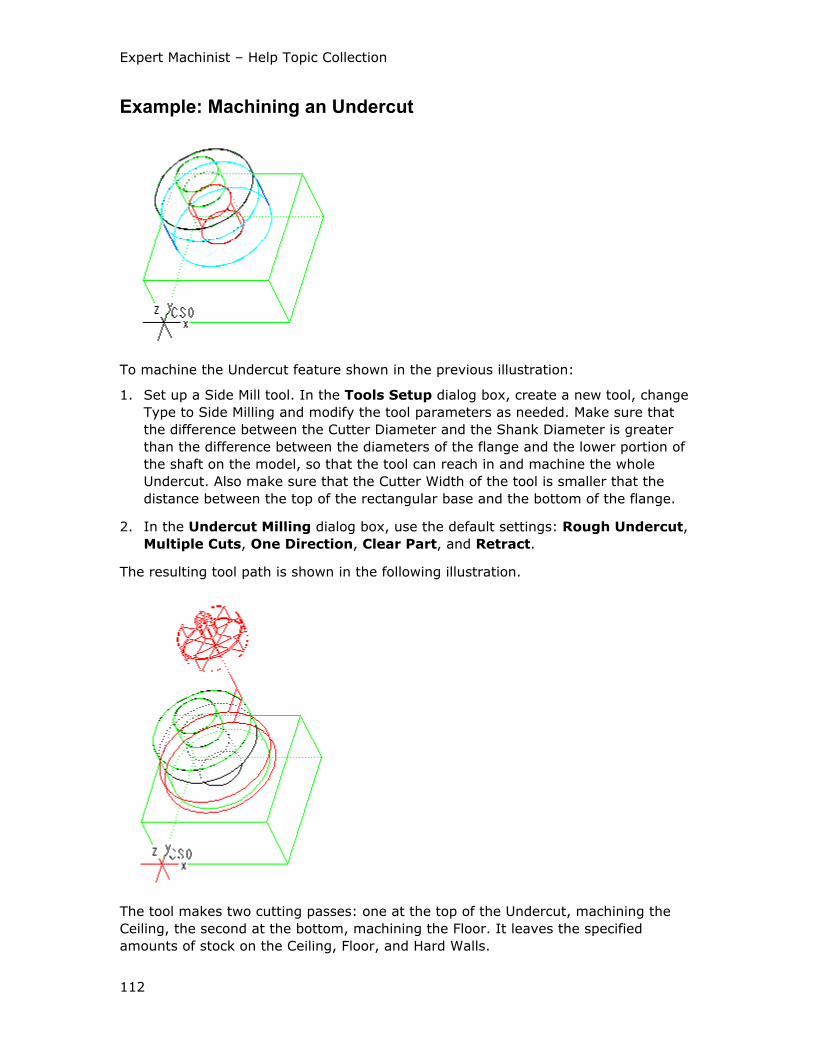
Expert Machinist – Help Topic Collection
112
Example: Machining an Undercut
To machine the Undercut feature shown in the previous illustration:
1. Set up a Side Mill tool. In the Tools Setup dialog box, create a new tool, change
Type to Side Milling and modify the tool parameters as needed. Make sure that
the difference between the Cutter Diameter and the Shank Diameter is greater
than the difference between the diameters of the flange and the lower portion of
the shaft on the model, so that the tool can reach in and machine the whole
Undercut. Also make sure that the Cutter Width of the tool is smaller that the
distance between the top of the rectangular base and the bottom of the flange.
2. In the Undercut Milling dialog box, use the default settings: Rough Undercut,
Multiple Cuts, One Direction, Clear Part, and Retract.
The resulting tool path is shown in the following illustration.
The tool makes two cutting passes: one at the top of the Undercut, machining the
Ceiling, the second at the bottom, machining the Floor. It leaves the specified
amounts of stock on the Ceiling, Floor, and Hard Walls.

Using Additional Modules
113
The following illustration shows the side view of the model when the Side Mill tool
starts machining the Ceiling of the Undercut.
The next illustration shows the side view of the model after the first machining pass,
when the Side Mill tool starts machining the Floor of the Undercut.
Top Chamfer Features
To Create a Top Chamfer Feature
A Top Chamfer feature can consist of a single chamfered edge, a single chain of
chamfered edges (open on both ends), or a single closed loop of chamfered edges
(for example, on top of a Pocket feature).
1. On the toolbar, click . Another way to access this functionality is from the top
menu bar: click NC Create > Features > Top Chamfer.
The Top Chamfer Feature dialog box opens with the following elements:
o Feature Name—The default feature name, such as TopChamfer1 (the
system increments the number for the next Top Chamfer feature). You can
type a customized name.
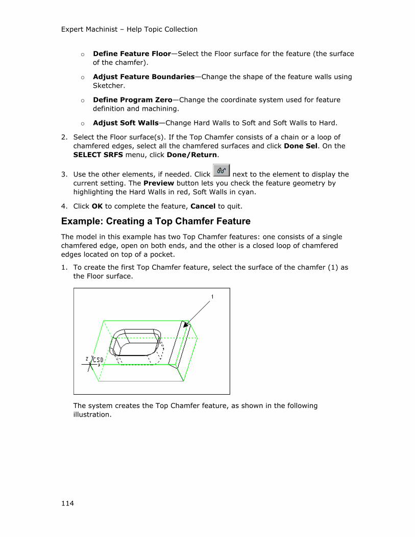
Expert Machinist – Help Topic Collection
114
o Define Feature Floor—Select the Floor surface for the feature (the surface
of the chamfer).
o Adjust Feature Boundaries—Change the shape of the feature walls using
Sketcher.
o Define Program Zero—Change the coordinate system used for feature
definition and machining.
o Adjust Soft Walls—Change Hard Walls to Soft and Soft Walls to Hard.
2. Select the Floor surface(s). If the Top Chamfer consists of a chain or a loop of
chamfered edges, select all the chamfered surfaces and click Done Sel. On the
SELECT SRFS menu, click Done/Return.
3. Use the other elements, if needed. Click next to the element to display the
current setting. The Preview button lets you check the feature geometry by
highlighting the Hard Walls in red, Soft Walls in cyan.
4. Click OK to complete the feature, Cancel to quit.
Example: Creating a Top Chamfer Feature
The model in this example has two Top Chamfer features: one consists of a single
chamfered edge, open on both ends, and the other is a closed loop of chamfered
edges located on top of a pocket.
1. To create the first Top Chamfer feature, select the surface of the chamfer (1) as
the Floor surface.
The system creates the Top Chamfer feature, as shown in the following
illustration.
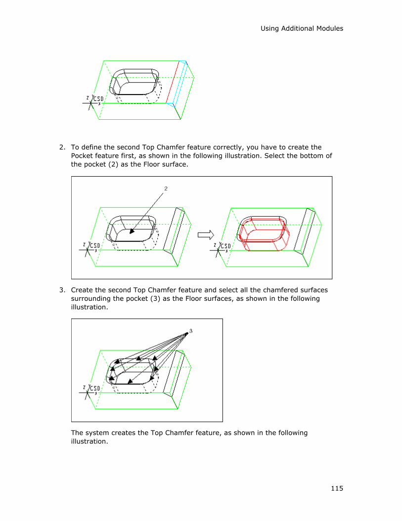
Using Additional Modules
115
2. To define the second Top Chamfer feature correctly, you have to create the
Pocket feature first, as shown in the following illustration. Select the bottom of
the pocket (2) as the Floor surface.
3. Create the second Top Chamfer feature and select all the chamfered surfaces
surrounding the pocket (3) as the Floor surfaces, as shown in the following
illustration.
The system creates the Top Chamfer feature, as shown in the following
illustration.
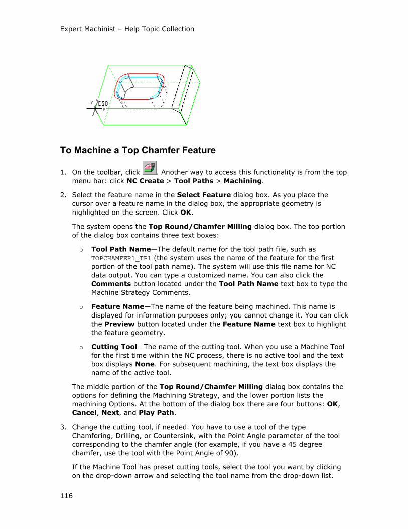
Expert Machinist – Help Topic Collection
116
To Machine a Top Chamfer Feature
1. On the toolbar, click . Another way to access this functionality is from the top
menu bar: click NC Create > Tool Paths > Machining.
2. Select the feature name in the Select Feature dialog box. As you place the
cursor over a feature name in the dialog box, the appropriate geometry is
highlighted on the screen. Click OK.
The system opens the Top Round/Chamfer Milling dialog box. The top portion
of the dialog box contains three text boxes:
o Tool Path Name—The default name for the tool path file, such as
TOPCHAMFER1_TP1 (the system uses the name of the feature for the first
portion of the tool path name). The system will use this file name for NC
data output. You can type a customized name. You can also click the
Comments button located under the Tool Path Name text box to type the
Machine Strategy Comments.
o Feature Name—The name of the feature being machined. This name is
displayed for information purposes only; you cannot change it. You can click
the Preview button located under the Feature Name text box to highlight
the feature geometry.
o Cutting Tool—The name of the cutting tool. When you use a Machine Tool
for the first time within the NC process, there is no active tool and the text
box displays None. For subsequent machining, the text box displays the
name of the active tool.
The middle portion of the Top Round/Chamfer Milling dialog box contains the
options for defining the Machining Strategy, and the lower portion lists the
machining Options. At the bottom of the dialog box there are four buttons: OK,
Cancel, Next, and Play Path.
3. Change the cutting tool, if needed. You have to use a tool of the type
Chamfering, Drilling, or Countersink, with the Point Angle parameter of the tool
corresponding to the chamfer angle (for example, if you have a 45 degree
chamfer, use the tool with the Point Angle of 90).
If the Machine Tool has preset cutting tools, select the tool you want by clicking
on the drop-down arrow and selecting the tool name from the drop-down list.
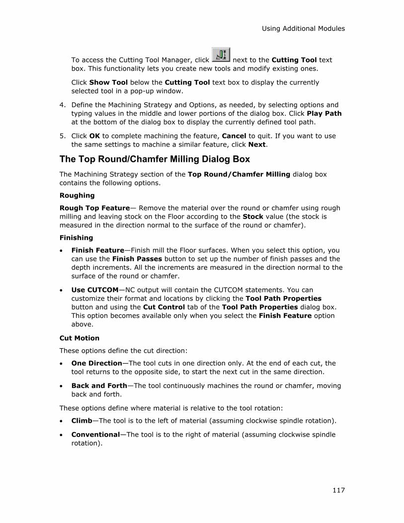
Using Additional Modules
117
To access the Cutting Tool Manager, click next to the Cutting Tool text
box. This functionality lets you create new tools and modify existing ones.
Click Show Tool below the Cutting Tool text box to display the currently
selected tool in a pop-up window.
4. Define the Machining Strategy and Options, as needed, by selecting options and
typing values in the middle and lower portions of the dialog box. Click Play Path
at the bottom of the dialog box to display the currently defined tool path.
5. Click OK to complete machining the feature, Cancel to quit. If you want to use
the same settings to machine a similar feature, click Next.
The Top Round/Chamfer Milling Dialog Box
The Machining Strategy section of the Top Round/Chamfer Milling dialog box
contains the following options.
Roughing
Rough Top Feature— Remove the material over the round or chamfer using rough
milling and leaving stock on the Floor according to the Stock value (the stock is
measured in the direction normal to the surface of the round or chamfer).
Finishing
• Finish Feature—Finish mill the Floor surfaces. When you select this option, you
can use the Finish Passes button to set up the number of finish passes and the
depth increments. All the increments are measured in the direction normal to the
surface of the round or chamfer.
• Use CUTCOM—NC output will contain the CUTCOM statements. You can
customize their format and locations by clicking the Tool Path Properties
button and using the Cut Control tab of the Tool Path Properties dialog box.
This option becomes available only when you select the Finish Feature option
above.
Cut Motion
These options define the cut direction:
• One Direction—The tool cuts in one direction only. At the end of each cut, the
tool returns to the opposite side, to start the next cut in the same direction.
• Back and Forth—The tool continuously machines the round or chamfer, moving
back and forth.
These options define where material is relative to the tool rotation:
• Climb—The tool is to the left of material (assuming clockwise spindle rotation).
• Conventional—The tool is to the right of material (assuming clockwise spindle
rotation).
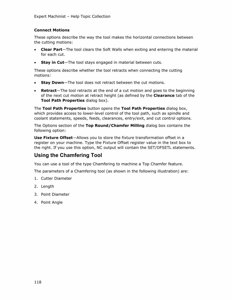
Expert Machinist – Help Topic Collection
118
Connect Motions
These options describe the way the tool makes the horizontal connections between
the cutting motions:
• Clear Part—The tool clears the Soft Walls when exiting and entering the material
for each cut.
• Stay in Cut—The tool stays engaged in material between cuts.
These options describe whether the tool retracts when connecting the cutting
motions:
• Stay Down—The tool does not retract between the cut motions.
• Retract—The tool retracts at the end of a cut motion and goes to the beginning
of the next cut motion at retract height (as defined by the Clearance tab of the
Tool Path Properties dialog box).
The Tool Path Properties button opens the Tool Path Properties dialog box,
which provides access to lower-level control of the tool path, such as spindle and
coolant statements, speeds, feeds, clearances, entry/exit, and cut control options.
The Options section of the Top Round/Chamfer Milling dialog box contains the
following option:
Use Fixture Offset—Allows you to store the fixture transformation offset in a
register on your machine. Type the Fixture Offset register value in the text box to
the right. If you use this option, NC output will contain the SET/OFSETL statements.
Using the Chamfering Tool
You can use a tool of the type Chamfering to machine a Top Chamfer feature.
The parameters of a Chamfering tool (as shown in the following illustration) are:
1. Cutter Diameter
2. Length
3. Point Diameter
4. Point Angle
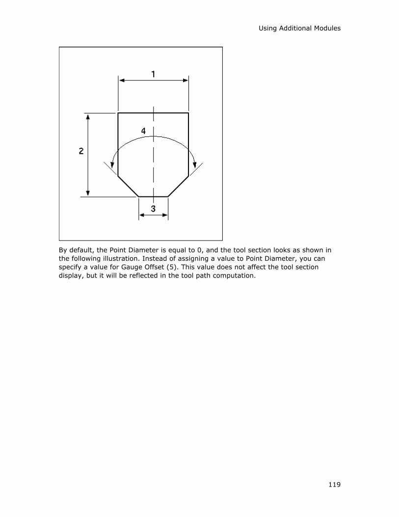
Using Additional Modules
119
By default, the Point Diameter is equal to 0, and the tool section looks as shown in
the following illustration. Instead of assigning a value to Point Diameter, you can
specify a value for Gauge Offset (5). This value does not affect the tool section
display, but it will be reflected in the tool path computation.
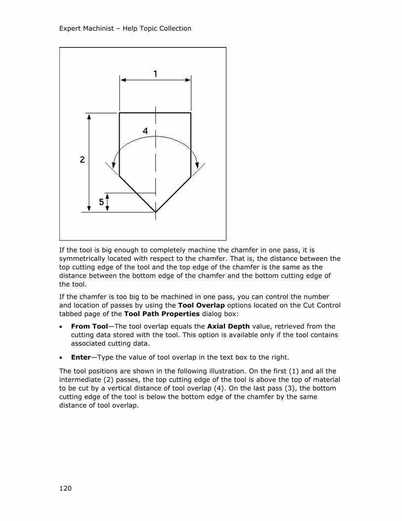
Expert Machinist – Help Topic Collection
120
If the tool is big enough to completely machine the chamfer in one pass, it is
symmetrically located with respect to the chamfer. That is, the distance between the
top cutting edge of the tool and the top edge of the chamfer is the same as the
distance between the bottom edge of the chamfer and the bottom cutting edge of
the tool.
If the chamfer is too big to be machined in one pass, you can control the number
and location of passes by using the Tool Overlap options located on the Cut Control
tabbed page of the Tool Path Properties dialog box:
• From Tool—The tool overlap equals the Axial Depth value, retrieved from the
cutting data stored with the tool. This option is available only if the tool contains
associated cutting data.
• Enter—Type the value of tool overlap in the text box to the right.
The tool positions are shown in the following illustration. On the first (1) and all the
intermediate (2) passes, the top cutting edge of the tool is above the top of material
to be cut by a vertical distance of tool overlap (4). On the last pass (3), the bottom
cutting edge of the tool is below the bottom edge of the chamfer by the same
distance of tool overlap.
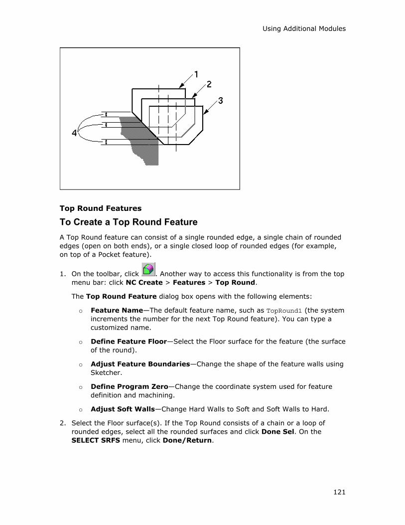
Using Additional Modules
121
Top Round Features
To Create a Top Round Feature
A Top Round feature can consist of a single rounded edge, a single chain of rounded
edges (open on both ends), or a single closed loop of rounded edges (for example,
on top of a Pocket feature).
1. On the toolbar, click . Another way to access this functionality is from the top
menu bar: click NC Create > Features > Top Round.
The Top Round Feature dialog box opens with the following elements:
o Feature Name—The default feature name, such as TopRound1 (the system
increments the number for the next Top Round feature). You can type a
customized name.
o Define Feature Floor—Select the Floor surface for the feature (the surface
of the round).
o Adjust Feature Boundaries—Change the shape of the feature walls using
Sketcher.
o Define Program Zero—Change the coordinate system used for feature
definition and machining.
o Adjust Soft Walls—Change Hard Walls to Soft and Soft Walls to Hard.
2. Select the Floor surface(s). If the Top Round consists of a chain or a loop of
rounded edges, select all the rounded surfaces and click Done Sel. On the
SELECT SRFS menu, click Done/Return.
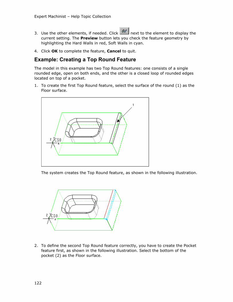
Expert Machinist – Help Topic Collection
122
3. Use the other elements, if needed. Click next to the element to display the
current setting. The Preview button lets you check the feature geometry by
highlighting the Hard Walls in red, Soft Walls in cyan.
4. Click OK to complete the feature, Cancel to quit.
Example: Creating a Top Round Feature
The model in this example has two Top Round features: one consists of a single
rounded edge, open on both ends, and the other is a closed loop of rounded edges
located on top of a pocket.
1. To create the first Top Round feature, select the surface of the round (1) as the
Floor surface.
The system creates the Top Round feature, as shown in the following illustration.
2. To define the second Top Round feature correctly, you have to create the Pocket
feature first, as shown in the following illustration. Select the bottom of the
pocket (2) as the Floor surface.
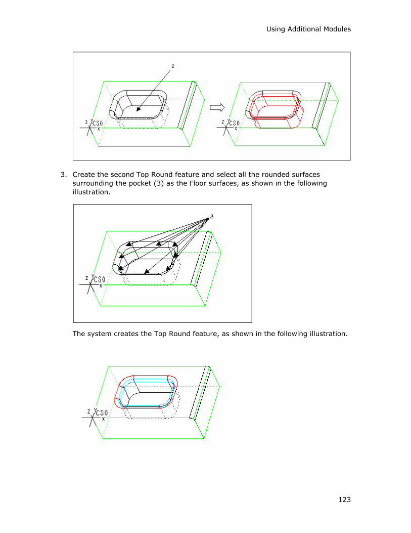
Using Additional Modules
123
3. Create the second Top Round feature and select all the rounded surfaces
surrounding the pocket (3) as the Floor surfaces, as shown in the following
illustration.
The system creates the Top Round feature, as shown in the following illustration.
Expert Machinist – Help Topic Collection
124
To Machine a Top Round Feature
1. On the toolbar, click . Another way to access this functionality is from the top
menu bar: click NC Create > Tool Paths > Machining.
2. Select the feature name in the Select Feature dialog box. As you place the
cursor over a feature name in the dialog box, the appropriate geometry is
highlighted on the screen. Click OK.
The system opens the Top Round/Chamfer Milling dialog box. The top portion
of the dialog box contains three text boxes:
o Tool Path Name—The default name for the tool path file, such as
TOPROUND1_TP1 (the system uses the name of the feature for the first
portion of the tool path name). The system will use this file name for NC
data output. You can type a customized name. You can also click the
Comments button located under the Tool Path Name text box to type the
Machine Strategy Comments.
o Feature Name—The name of the feature being machined. This name is
displayed for information purposes only; you cannot change it. You can click
the Preview button located under the Feature Name text box to highlight
the feature geometry.
o Cutting Tool—The name of the cutting tool. When you use a Machine Tool
for the first time within the NC process, there is no active tool and the text
box displays None. For subsequent machining, the text box displays the
name of the active tool.
The middle portion of the Top Round/Chamfer Milling dialog box contains the
options for defining the Machining Strategy, and the lower portion lists the
machining Options. At the bottom of the dialog box there are four buttons: OK,
Cancel, Next, and Play Path.
3. Change the cutting tool, if needed. You have to use either a tool of the type
Corner Rounding, with the Radius parameter of the tool equal to the radius of the
Top Round, or a sketched tool.
If the Machine Tool has preset cutting tools, select the tool you want by clicking
on the drop-down arrow and selecting the tool name from the drop-down list.
To access the Cutting Tool Manager, click next to the Cutting Tool text
box. This functionality lets you create new tools and modify existing ones.
Click Show Tool below the Cutting Tool text box to display the currently
selected tool in a pop-up window.
4. Define the Machining Strategy and Options, as needed, by selecting options and
typing values in the middle and lower portions of the dialog box. Click Play Path
at the bottom of the dialog box to display the currently defined tool path.
Using Additional Modules
125
5. Click OK to complete machining the feature, Cancel to quit. If you want to use
the same settings to machine a similar feature, click Next.
The Top Round/Chamfer Milling Dialog Box
The Machining Strategy section of the Top Round/Chamfer Milling dialog box
contains the following options.
Roughing
Rough Top Feature— Remove the material over the round or chamfer using rough
milling and leaving stock on the Floor according to the Stock value (the stock is
measured in the direction normal to the surface of the round or chamfer).
Finishing
• Finish Feature—Finish mill the Floor surfaces. When you select this option, you
can use the Finish Passes button to set up the number of finish passes and the
depth increments. All the increments are measured in the direction normal to the
surface of the round or chamfer.
• Use CUTCOM—NC output will contain the CUTCOM statements. You can
customize their format and locations by clicking the Tool Path Properties
button and using the Cut Control tab of the Tool Path Properties dialog box.
This option becomes available only when you select the Finish Feature option
above.
Cut Motion
These options define the cut direction:
• One Direction—The tool cuts in one direction only. At the end of each cut, the
tool returns to the opposite side, to start the next cut in the same direction.
• Back and Forth—The tool continuously machines the round or chamfer, moving
back and forth.
These options define where material is relative to the tool rotation:
• Climb—The tool is to the left of material (assuming clockwise spindle rotation).
• Conventional—The tool is to the right of material (assuming clockwise spindle
rotation).
Connect Motions
These options describe the way the tool makes the horizontal connections between
the cutting motions:
• Clear Part—The tool clears the Soft Walls when exiting and entering the material
for each cut.
• Stay in Cut—The tool stays engaged in material between cuts.
These options describe whether the tool retracts when connecting the cutting
motions:
• Stay Down—The tool does not retract between the cut motions.
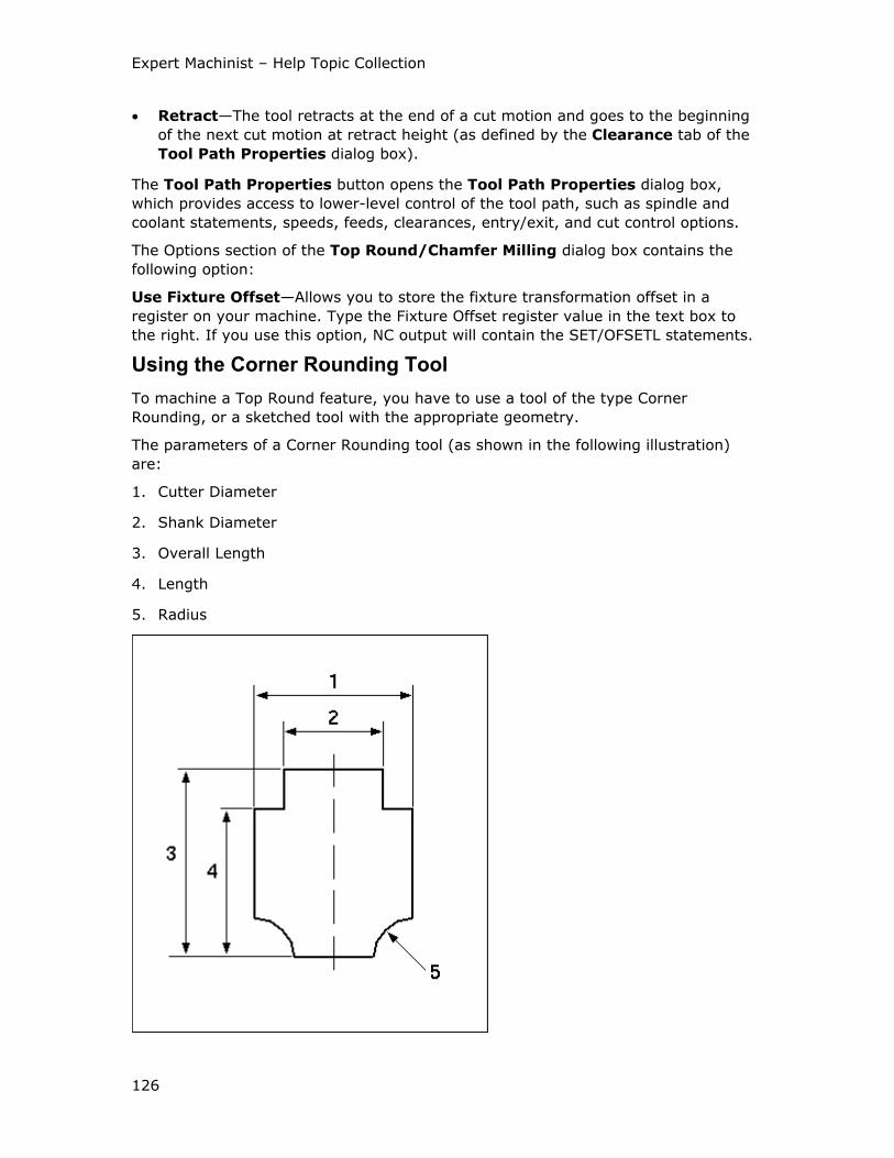
Expert Machinist – Help Topic Collection
126
• Retract—The tool retracts at the end of a cut motion and goes to the beginning
of the next cut motion at retract height (as defined by the Clearance tab of the
Tool Path Properties dialog box).
The Tool Path Properties button opens the Tool Path Properties dialog box,
which provides access to lower-level control of the tool path, such as spindle and
coolant statements, speeds, feeds, clearances, entry/exit, and cut control options.
The Options section of the Top Round/Chamfer Milling dialog box contains the
following option:
Use Fixture Offset—Allows you to store the fixture transformation offset in a
register on your machine. Type the Fixture Offset register value in the text box to
the right. If you use this option, NC output will contain the SET/OFSETL statements.
Using the Corner Rounding Tool
To machine a Top Round feature, you have to use a tool of the type Corner
Rounding, or a sketched tool with the appropriate geometry.
The parameters of a Corner Rounding tool (as shown in the following illustration)
are:
1. Cutter Diameter
2. Shank Diameter
3. Overall Length
4. Length
5. Radius
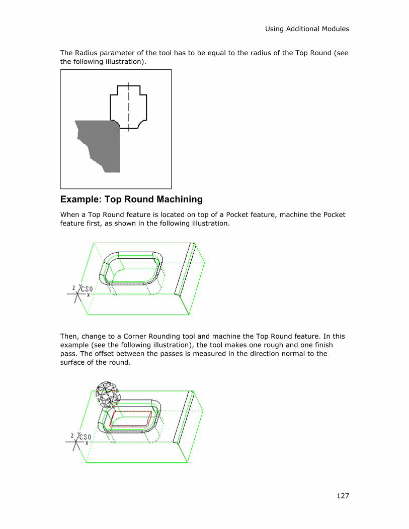
Using Additional Modules
127
The Radius parameter of the tool has to be equal to the radius of the Top Round (see
the following illustration).
Example: Top Round Machining
When a Top Round feature is located on top of a Pocket feature, machine the Pocket
feature first, as shown in the following illustration.
Then, change to a Corner Rounding tool and machine the Top Round feature. In this
example (see the following illustration), the tool makes one rough and one finish
pass. The offset between the passes is measured in the direction normal to the
surface of the round.
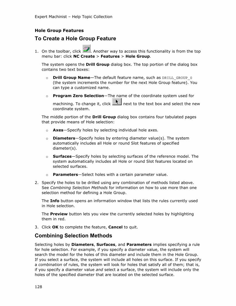
Expert Machinist – Help Topic Collection
128
Hole Group Features
To Create a Hole Group Feature
1. On the toolbar, click . Another way to access this functionality is from the top
menu bar: click NC Create > Features > Hole Group.
The system opens the Drill Group dialog box. The top portion of the dialog box
contains two text boxes:
o Drill Group Name—The default feature name, such as DRILL_GROUP_0
(the system increments the number for the next Hole Group feature). You
can type a customized name.
o Program Zero Selection—The name of the coordinate system used for
machining. To change it, click next to the text box and select the new
coordinate system.
The middle portion of the Drill Group dialog box contains four tabulated pages
that provide means of Hole selection:
o Axes—Specify holes by selecting individual hole axes.
o Diameters—Specify holes by entering diameter value(s). The system
automatically includes all Hole or round Slot features of specified
diameter(s).
o Surfaces—Specify holes by selecting surfaces of the reference model. The
system automatically includes all Hole or round Slot features located on
selected surfaces.
o Parameters—Select holes with a certain parameter value.
2. Specify the holes to be drilled using any combination of methods listed above.
See Combining Selection Methods for information on how to use more than one
selection method for defining a Hole Group.
The Info button opens an information window that lists the rules currently used
in Hole selection.
The Preview button lets you view the currently selected holes by highlighting
them in red.
3. Click OK to complete the feature, Cancel to quit.
Combining Selection Methods
Selecting holes by Diameters, Surfaces, and Parameters implies specifying a rule
for hole selection. For example, if you specify a diameter value, the system will
search the model for the holes of this diameter and include them in the Hole Group.
If you select a surface, the system will include all holes on this surface. If you specify
a combination of rules, the system will look for holes that satisfy all of them; that is,
if you specify a diameter value and select a surface, the system will include only the
holes of the specified diameter that are located on the selected surface.
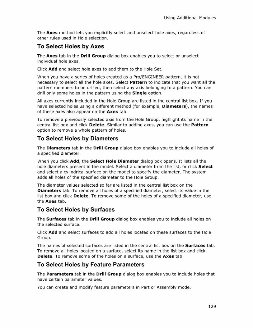
Using Additional Modules
129
The Axes method lets you explicitly select and unselect hole axes, regardless of
other rules used in Hole selection.
To Select Holes by Axes
The Axes tab in the Drill Group dialog box enables you to select or unselect
individual hole axes.
Click Add and select hole axes to add them to the Hole Set.
When you have a series of holes created as a Pro/ENGINEER pattern, it is not
necessary to select all the hole axes. Select Pattern to indicate that you want all the
pattern members to be drilled, then select any axis belonging to a pattern. You can
drill only some holes in the pattern using the Single option.
All axes currently included in the Hole Group are listed in the central list box. If you
have selected holes using a different method (for example, Diameters), the names
of these axes also appear on the Axes tab.
To remove a previously selected axis from the Hole Group, highlight its name in the
central list box and click Delete. Similar to adding axes, you can use the Pattern
option to remove a whole pattern of holes.
To Select Holes by Diameters
The Diameters tab in the Drill Group dialog box enables you to include all holes of
a specified diameter.
When you click Add, the Select Hole Diameter dialog box opens. It lists all the
hole diameters present in the model. Select a diameter from the list, or click Select
and select a cylindrical surface on the model to specify the diameter. The system
adds all holes of the specified diameter to the Hole Group.
The diameter values selected so far are listed in the central list box on the
Diameters tab. To remove all holes of a specified diameter, select its value in the
list box and click Delete. To remove some of the holes of a specified diameter, use
the Axes tab.
To Select Holes by Surfaces
The Surfaces tab in the Drill Group dialog box enables you to include all holes on
the selected surface.
Click Add and select surfaces to add all holes located on these surfaces to the Hole
Group.
The names of selected surfaces are listed in the central list box on the Surfaces tab.
To remove all holes located on a surface, select its name in the list box and click
Delete. To remove some of the holes on a surface, use the Axes tab.
To Select Holes by Feature Parameters
The Parameters tab in the Drill Group dialog box enables you to include holes that
have certain parameter values.
You can create and modify feature parameters in Part or Assembly mode.
Expert Machinist – Help Topic Collection
130
When you go to the Parameters tab, the Feature Parameter list box contains a
list of all feature parameters associated with Hole and Cosmetic Thread features in
the model. When you select a parameter name in the list, the Value text box below
will contain a drop-down list of all the currently present values for this parameter.
1. Select a name of parameter in the Feature Parameter list box.
2. Select an operator from the drop-down list. For parameter types Integer and
Real, the operators available are: "=", "!=", ">", "<". For other parameter types,
the only operators available are: "=" and "!=".
3. Select a value from the drop-down list, or type a value.
4. Click Add.
5. The system displays the selected parameter and its value in the list box below
and includes all holes with the appropriate feature parameter values in the Hole
Group.
To Machine a Hole Group Feature
1. On the toolbar, click . Another way to access this functionality is from the top
menu bar: click NC Create > Tool Paths > Machining.
2. Select the feature name in the Select Feature dialog box. As you place the
cursor over a feature name in the dialog box, the appropriate geometry is
highlighted on the screen. Click OK.
The system opens the Drilling Strategy dialog box. The top portion of the dialog
box contains three text boxes:
o Tool Path Name—The default name for the tool path file, such as
HOLE_PATTERN1_TP1 (the system uses the name of the feature for the first
portion of the tool path name). The system will use this file name for NC
data output. You can type a customized name. You can also click the
Comments button located under the Tool Path Name text box to type the
Machine Strategy Comments.
o Feature Name—The name of the Hole Group being machined. You can
click the Add button located under the Feature Name text box to select
other Hole Group features present in the model. The Remove button lets
you remove previously selected Hole Group features. All the names of the
Hole Group features selected for machining are displayed in the Feature
Name text box. You can click the Preview button located under the
Feature Name text box to highlight the holes being machined.
o Cutting Tool—The name of the cutting tool. When you use a Machine Tool
for the first time within the NC process, there is no active tool and the text
box displays None. For subsequent machining, the text box displays the
name of the active tool.
The middle portion of the Drilling Strategy dialog box contains the options for
defining the Holemaking Method, and the lower portion lists the machining
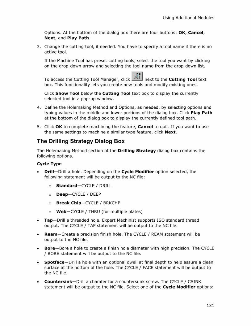
Using Additional Modules
131
Options. At the bottom of the dialog box there are four buttons: OK, Cancel,
Next, and Play Path.
3. Change the cutting tool, if needed. You have to specify a tool name if there is no
active tool.
If the Machine Tool has preset cutting tools, select the tool you want by clicking
on the drop-down arrow and selecting the tool name from the drop-down list.
To access the Cutting Tool Manager, click next to the Cutting Tool text
box. This functionality lets you create new tools and modify existing ones.
Click Show Tool below the Cutting Tool text box to display the currently
selected tool in a pop-up window.
4. Define the Holemaking Method and Options, as needed, by selecting options and
typing values in the middle and lower portions of the dialog box. Click Play Path
at the bottom of the dialog box to display the currently defined tool path.
5. Click OK to complete machining the feature, Cancel to quit. If you want to use
the same settings to machine a similar type feature, click Next.
The Drilling Strategy Dialog Box
The Holemaking Method section of the Drilling Strategy dialog box contains the
following options.
Cycle Type
• Drill—Drill a hole. Depending on the Cycle Modifier option selected, the
following statement will be output to the NC file:
o Standard—CYCLE / DRILL
o Deep—CYCLE / DEEP
o Break Chip—CYCLE / BRKCHP
o Web—CYCLE / THRU (for multiple plates)
• Tap—Drill a threaded hole. Expert Machinist supports ISO standard thread
output. The CYCLE / TAP statement will be output to the NC file.
• Ream—Create a precision finish hole. The CYCLE / REAM statement will be
output to the NC file.
• Bore—Bore a hole to create a finish hole diameter with high precision. The CYCLE
/ BORE statement will be output to the NC file.
• Spotface—Drill a hole with an optional dwell at final depth to help assure a clean
surface at the bottom of the hole. The CYCLE / FACE statement will be output to
the NC file.
• Countersink—Drill a chamfer for a countersunk screw. The CYCLE / CSINK
statement will be output to the NC file. Select one of the Cycle Modifier options:
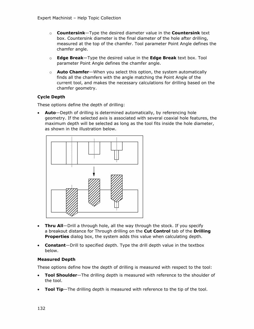
Expert Machinist – Help Topic Collection
132
o Countersink—Type the desired diameter value in the Countersink text
box. Countersink diameter is the final diameter of the hole after drilling,
measured at the top of the chamfer. Tool parameter Point Angle defines the
chamfer angle.
o Edge Break—Type the desired value in the Edge Break text box. Tool
parameter Point Angle defines the chamfer angle.
o Auto Chamfer—When you select this option, the system automatically
finds all the chamfers with the angle matching the Point Angle of the
current tool, and makes the necessary calculations for drilling based on the
chamfer geometry.
Cycle Depth
These options define the depth of drilling:
• Auto—Depth of drilling is determined automatically, by referencing hole
geometry. If the selected axis is associated with several coaxial hole features, the
maximum depth will be selected as long as the tool fits inside the hole diameter,
as shown in the illustration below.
• Thru All—Drill a through hole, all the way through the stock. If you specify
a breakout distance for Through drilling on the Cut Control tab of the Drilling
Properties dialog box, the system adds this value when calculating depth.
• Constant—Drill to specified depth. Type the drill depth value in the textbox
below.
Measured Depth
These options define how the depth of drilling is measured with respect to the tool:
• Tool Shoulder—The drilling depth is measured with reference to the shoulder of
the tool.
• Tool Tip—The drilling depth is measured with reference to the tip of the tool.
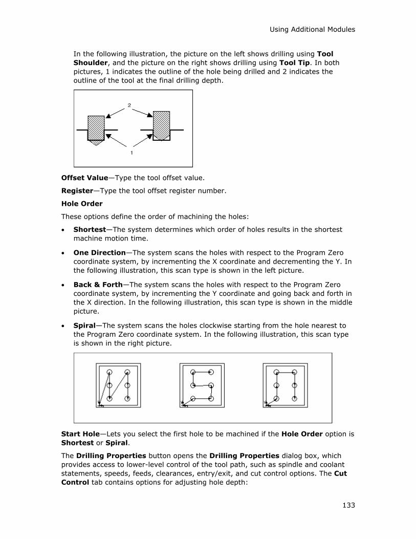
Using Additional Modules
133
In the following illustration, the picture on the left shows drilling using Tool
Shoulder, and the picture on the right shows drilling using Tool Tip. In both
pictures, 1 indicates the outline of the hole being drilled and 2 indicates the
outline of the tool at the final drilling depth.
Offset Value—Type the tool offset value.
Register—Type the tool offset register number.
Hole Order
These options define the order of machining the holes:
• Shortest—The system determines which order of holes results in the shortest
machine motion time.
• One Direction—The system scans the holes with respect to the Program Zero
coordinate system, by incrementing the X coordinate and decrementing the Y. In
the following illustration, this scan type is shown in the left picture.
• Back & Forth—The system scans the holes with respect to the Program Zero
coordinate system, by incrementing the Y coordinate and going back and forth in
the X direction. In the following illustration, this scan type is shown in the middle
picture.
• Spiral—The system scans the holes clockwise starting from the hole nearest to
the Program Zero coordinate system. In the following illustration, this scan type
is shown in the right picture.
Start Hole—Lets you select the first hole to be machined if the Hole Order option is
Shortest or Spiral.
The Drilling Properties button opens the Drilling Properties dialog box, which
provides access to lower-level control of the tool path, such as spindle and coolant
statements, speeds, feeds, clearances, entry/exit, and cut control options. The Cut
Control tab contains options for adjusting hole depth:
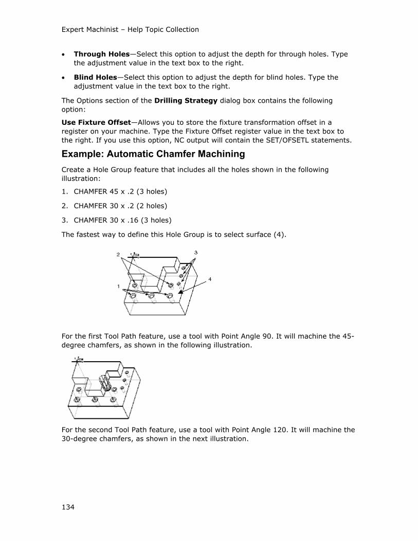
Expert Machinist – Help Topic Collection
134
• Through Holes—Select this option to adjust the depth for through holes. Type
the adjustment value in the text box to the right.
• Blind Holes—Select this option to adjust the depth for blind holes. Type the
adjustment value in the text box to the right.
The Options section of the Drilling Strategy dialog box contains the following
option:
Use Fixture Offset—Allows you to store the fixture transformation offset in a
register on your machine. Type the Fixture Offset register value in the text box to
the right. If you use this option, NC output will contain the SET/OFSETL statements.
Example: Automatic Chamfer Machining
Create a Hole Group feature that includes all the holes shown in the following
illustration:
1. CHAMFER 45 x .2 (3 holes)
2. CHAMFER 30 x .2 (2 holes)
3. CHAMFER 30 x .16 (3 holes)
The fastest way to define this Hole Group is to select surface (4).
For the first Tool Path feature, use a tool with Point Angle 90. It will machine the 45-
degree chamfers, as shown in the following illustration.
For the second Tool Path feature, use a tool with Point Angle 120. It will machine the
30-degree chamfers, as shown in the next illustration.
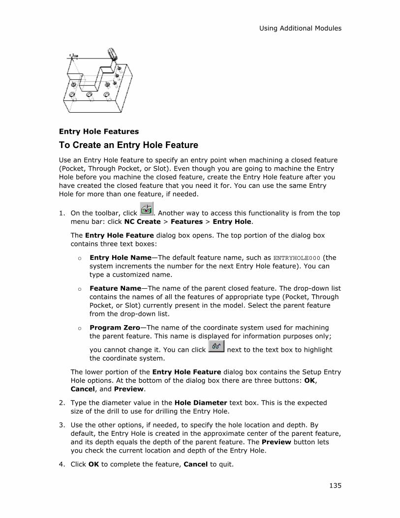
Using Additional Modules
135
Entry Hole Features
To Create an Entry Hole Feature
Use an Entry Hole feature to specify an entry point when machining a closed feature
(Pocket, Through Pocket, or Slot). Even though you are going to machine the Entry
Hole before you machine the closed feature, create the Entry Hole feature after you
have created the closed feature that you need it for. You can use the same Entry
Hole for more than one feature, if needed.
1. On the toolbar, click . Another way to access this functionality is from the top
menu bar: click NC Create > Features > Entry Hole.
The Entry Hole Feature dialog box opens. The top portion of the dialog box
contains three text boxes:
o Entry Hole Name—The default feature name, such as ENTRYHOLE000 (the
system increments the number for the next Entry Hole feature). You can
type a customized name.
o Feature Name—The name of the parent closed feature. The drop-down list
contains the names of all the features of appropriate type (Pocket, Through
Pocket, or Slot) currently present in the model. Select the parent feature
from the drop-down list.
o Program Zero—The name of the coordinate system used for machining
the parent feature. This name is displayed for information purposes only;
you cannot change it. You can click next to the text box to highlight
the coordinate system.
The lower portion of the Entry Hole Feature dialog box contains the Setup Entry
Hole options. At the bottom of the dialog box there are three buttons: OK,
Cancel, and Preview.
2. Type the diameter value in the Hole Diameter text box. This is the expected
size of the drill to use for drilling the Entry Hole.
3. Use the other options, if needed, to specify the hole location and depth. By
default, the Entry Hole is created in the approximate center of the parent feature,
and its depth equals the depth of the parent feature. The Preview button lets
you check the current location and depth of the Entry Hole.
4. Click OK to complete the feature, Cancel to quit.
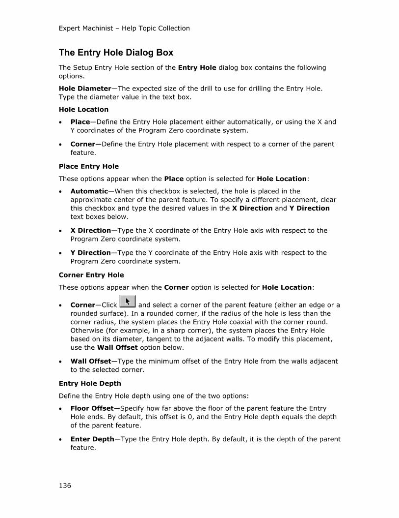
Expert Machinist – Help Topic Collection
136
The Entry Hole Dialog Box
The Setup Entry Hole section of the Entry Hole dialog box contains the following
options.
Hole Diameter—The expected size of the drill to use for drilling the Entry Hole.
Type the diameter value in the text box.
Hole Location
• Place—Define the Entry Hole placement either automatically, or using the X and
Y coordinates of the Program Zero coordinate system.
• Corner—Define the Entry Hole placement with respect to a corner of the parent
feature.
Place Entry Hole
These options appear when the Place option is selected for Hole Location:
• Automatic—When this checkbox is selected, the hole is placed in the
approximate center of the parent feature. To specify a different placement, clear
this checkbox and type the desired values in the X Direction and Y Direction
text boxes below.
• X Direction—Type the X coordinate of the Entry Hole axis with respect to the
Program Zero coordinate system.
• Y Direction—Type the Y coordinate of the Entry Hole axis with respect to the
Program Zero coordinate system.
Corner Entry Hole
These options appear when the Corner option is selected for Hole Location:
• Corner—Click and select a corner of the parent feature (either an edge or a
rounded surface). In a rounded corner, if the radius of the hole is less than the
corner radius, the system places the Entry Hole coaxial with the corner round.
Otherwise (for example, in a sharp corner), the system places the Entry Hole
based on its diameter, tangent to the adjacent walls. To modify this placement,
use the Wall Offset option below.
• Wall Offset—Type the minimum offset of the Entry Hole from the walls adjacent
to the selected corner.
Entry Hole Depth
Define the Entry Hole depth using one of the two options:
• Floor Offset—Specify how far above the floor of the parent feature the Entry
Hole ends. By default, this offset is 0, and the Entry Hole depth equals the depth
of the parent feature.
• Enter Depth—Type the Entry Hole depth. By default, it is the depth of the parent
feature.
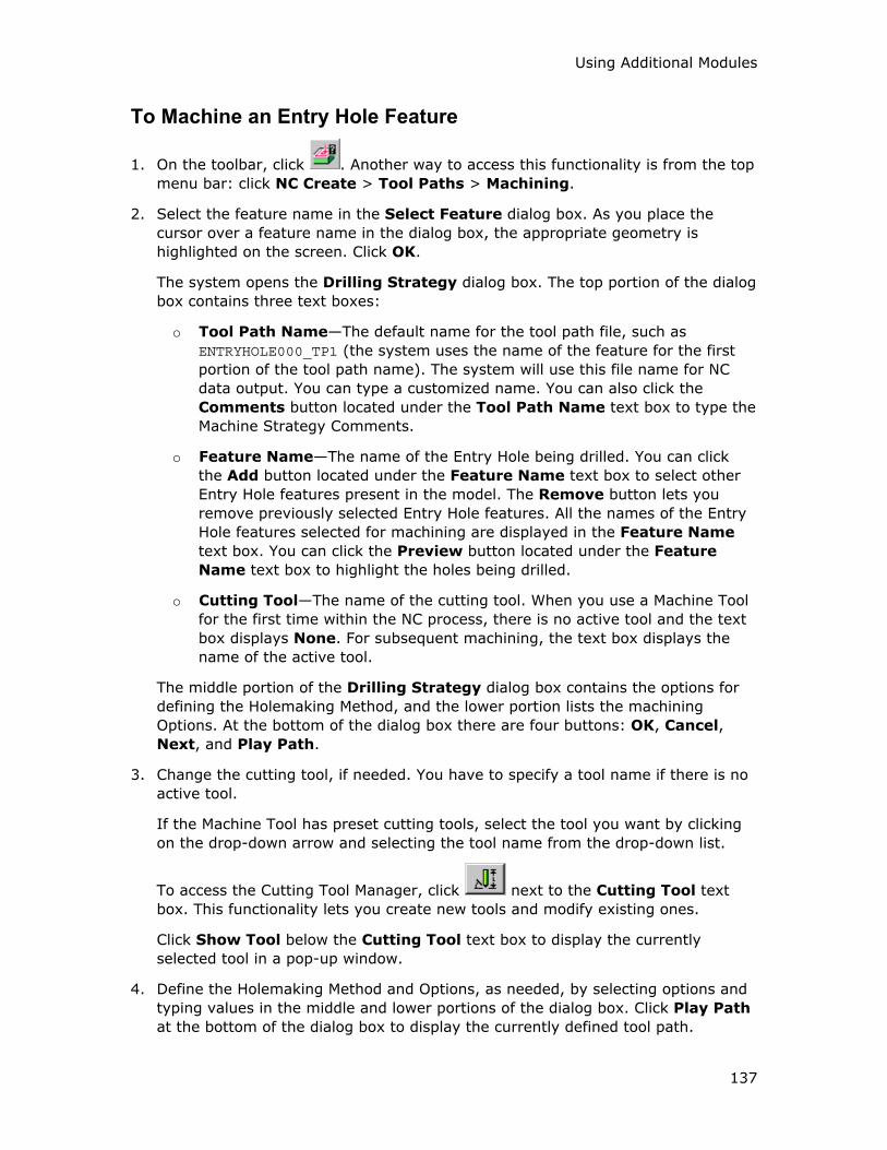
Using Additional Modules
137
To Machine an Entry Hole Feature
1. On the toolbar, click . Another way to access this functionality is from the top
menu bar: click NC Create > Tool Paths > Machining.
2. Select the feature name in the Select Feature dialog box. As you place the
cursor over a feature name in the dialog box, the appropriate geometry is
highlighted on the screen. Click OK.
The system opens the Drilling Strategy dialog box. The top portion of the dialog
box contains three text boxes:
o Tool Path Name—The default name for the tool path file, such as
ENTRYHOLE000_TP1 (the system uses the name of the feature for the first
portion of the tool path name). The system will use this file name for NC
data output. You can type a customized name. You can also click the
Comments button located under the Tool Path Name text box to type the
Machine Strategy Comments.
o Feature Name—The name of the Entry Hole being drilled. You can click
the Add button located under the Feature Name text box to select other
Entry Hole features present in the model. The Remove button lets you
remove previously selected Entry Hole features. All the names of the Entry
Hole features selected for machining are displayed in the Feature Name
text box. You can click the Preview button located under the Feature
Name text box to highlight the holes being drilled.
o Cutting Tool—The name of the cutting tool. When you use a Machine Tool
for the first time within the NC process, there is no active tool and the text
box displays None. For subsequent machining, the text box displays the
name of the active tool.
The middle portion of the Drilling Strategy dialog box contains the options for
defining the Holemaking Method, and the lower portion lists the machining
Options. At the bottom of the dialog box there are four buttons: OK, Cancel,
Next, and Play Path.
3. Change the cutting tool, if needed. You have to specify a tool name if there is no
active tool.
If the Machine Tool has preset cutting tools, select the tool you want by clicking
on the drop-down arrow and selecting the tool name from the drop-down list.
To access the Cutting Tool Manager, click next to the Cutting Tool text
box. This functionality lets you create new tools and modify existing ones.
Click Show Tool below the Cutting Tool text box to display the currently
selected tool in a pop-up window.
4. Define the Holemaking Method and Options, as needed, by selecting options and
typing values in the middle and lower portions of the dialog box. Click Play Path
at the bottom of the dialog box to display the currently defined tool path.
Expert Machinist – Help Topic Collection
138
5. Click OK to complete machining the feature, Cancel to quit. If you want to use
the same settings to machine a similar type feature, click Next.
Free Form Machining
To Machine a Free Form Feature
Unlike other machining strategies in Expert Machinist, Free Form machining does not
require creating a feature and then machining it. You define the machining strategy
in one step by referencing model geometry (or sketching) and specifying the
machining method and options, as needed.
Note: You can also use the Free Form feature just to supply certain CL commands
between other tool paths, if needed. In this case, you do not have to specify a tool or
define the Drive Geometry. When the Freeform Milling dialog box opens, click Play
Path and insert the required CL commands.
1. On the toolbar, click .
The Freeform Milling dialog box opens. The top portion of the dialog box
contains two text boxes:
o Tool Path Name—The default name for the tool path file, such as
FREE_MILLING_TP1. The system will use this file name for NC data output.
You can type a customized name. You can also click the Comments button
located under the Tool Path Name text box to type the Machine Strategy
Comments.
o Cutting Tool—The name of the cutting tool. When you use a Machine Tool
for the first time within the NC process, there is no active tool and the text
box displays None. For subsequent machining, the text box displays the
name of the active tool.
The middle portion of the Freeform Milling dialog box contains the options for
defining the Drive Geometry and the Machining Method, and the lower portion
lists the machining Options. At the bottom of the dialog box there are four
buttons: OK, Cancel, Next, and Play Path.
2. Change the cutting tool, if needed.
If the Machine Tool has preset cutting tools, select the tool you want by clicking
on the drop-down arrow and selecting the tool name from the drop-down list.
To access the Cutting Tool Manager, click next to the Cutting Tool text
box. This functionality lets you create new tools and modify existing ones.
Note: Unlike other machining features, for Free Form machining you can use a
sketched tool.
Click Show Tool below the Cutting Tool text box to display the currently
selected tool in a pop-up window.
Using Additional Modules
139
3. Define the Drive Geometry. The Drive Geometry defines the tool trajectory in the
XY-plane of the Program Zero coordinate system. You can:
o Next to Use Model Edges, click and select edges from the reference
model or from the stock. To verify your selection, click . The system
highlights the selected edges in cyan and indicates with an arrow which side
the tool will be on. Click Flip, if needed, to change the side.
o Click next to the Sketch label and sketch the trajectory of the tool in
the XY-plane of the Program Zero coordinate system.
4. Define the Cut Depth, that is, the height of the last tool pass. Click next to
Cut Depth and then use one of the CTM DEPTH menu commands:
o Specify Plane—Select a planar surface or create a datum plane parallel to
the XY-plane of the Program Zero coordinate system.
o Z Depth—Type a value along the z-axis of the Program Zero coordinate
system.
5. Define the Machining Method and Options, as needed, by selecting options and
typing values in the middle and lower portions of the dialog box. Click Play Path
at the bottom of the dialog box to display the currently defined tool path.
6. Click OK to complete machining the feature, Cancel to quit. If you want to use
the same settings to machine a similar feature, click Next.
Note: When you create a Free Form tool path, the system removes the
appropriate stock material, the same as for the other feature types. However, for
Free Form features you can specify that the system does not create the
automatic material removal. To do this, set the configuration option
freeform_toolpath_matrem to no.
The Freeform Milling Dialog Box
The Drive Geometry section of the Freeform Milling dialog box contains the
following elements.
• Program Zero—Change the coordinate system used for machining, if desired.
• Drive Geometry—Define the tool trajectory in the XY-plane of the Program Zero
coordinate system:
o Use Model Edges—Select edges from the reference model or from the
stock.
o Sketch—Sketch the trajectory of the tool in the XY-plane of the Program
Zero coordinate system.
• Cut Depth—Define the height of the last tool pass.
The Machining Method section of the Freeform Milling dialog box contains the
following options.
Expert Machinist – Help Topic Collection
140
Direction of Cut
These options are available when you define Drive Geometry by selecting model
edges. They define where material is relative to the tool rotation:
• Climb—The tool is to the left of material (assuming clockwise spindle rotation).
• Conventional—The tool is to the right of material (assuming clockwise spindle
rotation).
Tool Side
These options are available when you define Drive Geometry by sketching. They
define where the tool is relative to the sketch:
• Left—The tool is to the left from the sketch.
• Right—The tool is to the right from the sketch.
• On—The tool follows the sketch. Use the Material Side options to specify cutter
compensation.
Material Side
These options define how to apply cutter compensation when the tool follows the
sketch:
• Left—Material is to the left.
• Right—Material is to the right.
Cut Ordering
These options define the order of machining if you specify multiple cuts and passes:
• X-Y First—The tool makes all the cuts at a specific depth and then moves to the
next depth.
• Z First—The tool makes multiple passes to depth and then goes to the next cut.
The Multiple Cuts button opens the Finish Cuts dialog box, where you can set up
the number and depth of finish cuts.
The Multiple Passes button opens the Finish Passes dialog box, where you can set
up the number of finish passes and the depth increments.
The Tool Path Properties button opens the Tool Path Properties dialog box,
which provides access to lower-level control of the tool path, such as spindle and
coolant statements, speeds, feeds, clearances, entry/exit, and cut control options.
The Options section of the Freeform Milling dialog box contains the following
options:
• Use Cutcom—NC output will contain the CUTCOM statements. You can
customize their format and locations by clicking the Tool Path Properties
button and using the Cut Control tab of the Tool Path Properties dialog box.
• Use Fixture Offset—Allows you to store the fixture transformation offset in a
register on your machine. Type the Fixture Offset register value in the text box to
Using Additional Modules
141
the right. If you use this option, NC output will contain the SET/OFSETL
statements.
Tool Path Display and Output
About Displaying the Tool Path
You can display the tool motion and a simulation of the tool before you complete
creating a tool path, to verify the tool path and make a visual check for interference
with fixtures. You can also display the tool motion, along with a tool simulation, for
existing tool paths, and for a whole operation. All simulated tool dimensions
represent the parameters defined during tool setup.
Whenever you display tool motion for a tool path or an operation, the system opens
the PLAY PATH dialog box. The collapsible upper portion of this dialog box lists the
cutter location (CL) data for the tool path or operation, as it would be output to a CL
data file through Output > Create CL File. You can save this CL data in a CL file or
an MCD file directly from the PLAY PATH dialog box, by clicking the appropriate
option in the File menu.
The lower portion contains the following buttons: Play Forward, Play Back, Stop,
Fast Forward and Rewind, as well as Go To Next CL Record and Go To
Previous CL Record. It also contains the buttons for positioning the cutting tool and
for accessing the Tool Clearance functionality, and a slider to adjust the display
speed.
When displaying the tool motion, you can make the tool stop at certain points by
adding break points. You can also insert customized CL commands, such as the
specific postprocessor words required for correct NC output, at desired locations
within the CL file. When you save the CL data, these commands will be output to the
CL file. If you add a tool motion command, the corresponding motion will be also
shown in the tool path display on the screen.
To Display the Tool Path
You can display tool motion for a single tool path or for a whole operation. To display
tool motion for an operation, select the operation name in the Model Tree window. To
display tool motion for a single tool path, select the name of the corresponding tool
path in the Model Tree window.
Note: When you are machining a feature, or creating a Free Form tool path, you can
display the tool path as it is currently defined by clicking the Play Path button at the
bottom of the dialog box.
1. In the Model Tree window, select the operation or the Tool Path that you want to
display. Click the right mouse button and select Tool Path Player from the pop-
up menu. Or, on the top menu bar, click NC Create > Output > Tool Path
Player.
The system opens the PLAY PATH dialog box and displays the cutting tool
simulation in the initial location.
2. Click the Play Forward button to start playing the tool motion.
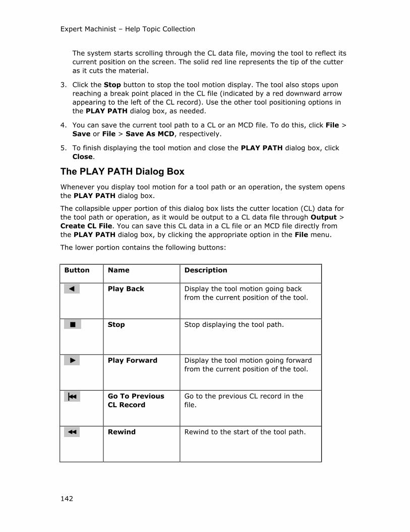
Expert Machinist – Help Topic Collection
142
The system starts scrolling through the CL data file, moving the tool to reflect its
current position on the screen. The solid red line represents the tip of the cutter
as it cuts the material.
3. Click the Stop button to stop the tool motion display. The tool also stops upon
reaching a break point placed in the CL file (indicated by a red downward arrow
appearing to the left of the CL record). Use the other tool positioning options in
the PLAY PATH dialog box, as needed.
4. You can save the current tool path to a CL or an MCD file. To do this, click File >
Save or File > Save As MCD, respectively.
5. To finish displaying the tool motion and close the PLAY PATH dialog box, click
Close.
The PLAY PATH Dialog Box
Whenever you display tool motion for a tool path or an operation, the system opens
the PLAY PATH dialog box.
The collapsible upper portion of this dialog box lists the cutter location (CL) data for
the tool path or operation, as it would be output to a CL data file through Output >
Create CL File. You can save this CL data in a CL file or an MCD file directly from
the PLAY PATH dialog box, by clicking the appropriate option in the File menu.
The lower portion contains the following buttons:
Button Name Description
Play Back Display the tool motion going back
from the current position of the tool.
Stop Stop displaying the tool path.
Play Forward Display the tool motion going forward
from the current position of the tool.
Go To Previous
CL Record
Go to the previous CL record in the
file.
Rewind Rewind to the start of the tool path.
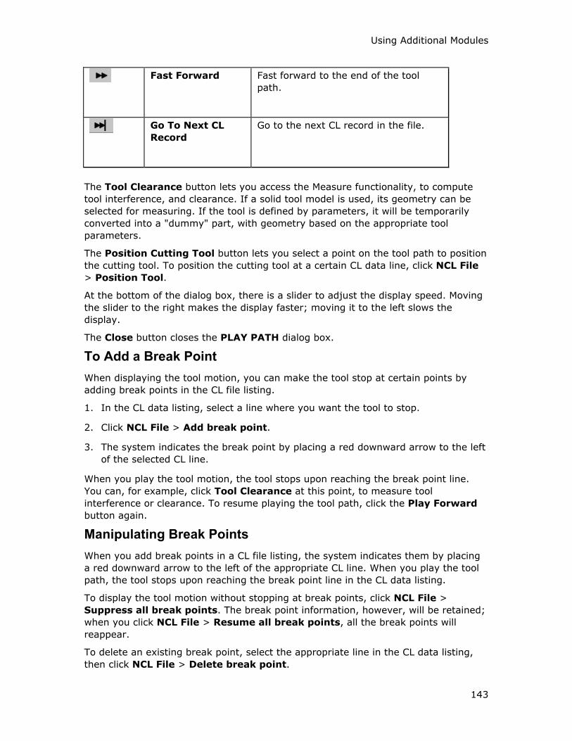
Using Additional Modules
143
Fast Forward Fast forward to the end of the tool
path.
Go To Next CL
Record
Go to the next CL record in the file.
The Tool Clearance button lets you access the Measure functionality, to compute
tool interference, and clearance. If a solid tool model is used, its geometry can be
selected for measuring. If the tool is defined by parameters, it will be temporarily
converted into a "dummy" part, with geometry based on the appropriate tool
parameters.
The Position Cutting Tool button lets you select a point on the tool path to position
the cutting tool. To position the cutting tool at a certain CL data line, click NCL File
> Position Tool.
At the bottom of the dialog box, there is a slider to adjust the display speed. Moving
the slider to the right makes the display faster; moving it to the left slows the
display.
The Close button closes the PLAY PATH dialog box.
To Add a Break Point
When displaying the tool motion, you can make the tool stop at certain points by
adding break points in the CL file listing.
1. In the CL data listing, select a line where you want the tool to stop.
2. Click NCL File > Add break point.
3. The system indicates the break point by placing a red downward arrow to the left
of the selected CL line.
When you play the tool motion, the tool stops upon reaching the break point line.
You can, for example, click Tool Clearance at this point, to measure tool
interference or clearance. To resume playing the tool path, click the Play Forward
button again.
Manipulating Break Points
When you add break points in a CL file listing, the system indicates them by placing
a red downward arrow to the left of the appropriate CL line. When you play the tool
path, the tool stops upon reaching the break point line in the CL data listing.
To display the tool motion without stopping at break points, click NCL File >
Suppress all break points. The break point information, however, will be retained;
when you click NCL File > Resume all break points, all the break points will
reappear.
To delete an existing break point, select the appropriate line in the CL data listing,
then click NCL File > Delete break point.
Expert Machinist – Help Topic Collection
144
To Position the Tool
When you play the tool path, the position of the cutting tool on the screen
corresponds to the position of the cursor in the CL data listing in the top portion of
the PLAY PATH dialog box.
To change the tool position, use one of the following methods:
• Click the Position Cutting Tool button in the lower portion of the PLAY PATH
dialog box and select a point on the tool path to position the cutting tool.
• Select a line in the CL data listing, then click NCL File > Position Tool to
position the tool at this line.
To Insert a CL Command
You can insert a customized CL command anywhere along the tool path. Use this
functionality to add the specific postprocessor words required for correct NC output.
Note: If you want the customized CL command to be located before or after a
specific event on the tool path (for example, before each pass, or after the final
retract), and to maintain its location even if the tool path changes, use the Automatic
Command Placement functionality. You can access it through the Tool Path
Properties dialog box.
1. Click NCL File > Insert CL Command.
The CL Command dialog box opens.
2. To select location for the CL command, click and select either a point on the
tool path on the screen or a line in the CL file listing.
3. Specify the command contents using one of the following methods:
o Place the cursor in the Command text box and type the command, line-by-
line. Note that this method does not provide syntax checking.
o Click Menu and compose the command by selecting appropriate keywords
from the syntax menus and typing values in response to the system
prompts.
o Click File and read in a file containing the CL command lines. The browser
window will appear to let you select the file name. The expected file
extension is .cmd.
Notes:
o You can edit the contents of the Command text box at any point by placing
the cursor in it and using the keyboard.
o If you supply more than one command line, they will be treated as a
"block", that is, you will be able to move, copy, or delete only the whole
block of command lines.
Using Additional Modules
145
4. The Preview button inserts the command line(s) in the CL file at the selected
location to let you preview the result. Click OK to insert the command at selected
location, Cancel—to quit inserting the command.
Using Parameters in CL Commands
When typing values for CL commands, you can input model parameters, preceded by
an ampersand(&) sign. If there is a corresponding parameter defined in relations, its
value will be used in the CL command. If the parameter is not found, the system will
prompt you for the parameter’s type and value, and this parameter will be added to
the relations. This way, the CL command can be changed at the top level (through
Relations).
To Delete a CL Command
You can only delete user-defined CL commands, that is, the CL commands previously
added by using the Insert CL Command option.
1. Select a user-defined CL command.
2. Click NCL File > Delete CL Command.
3. The system deletes the selected command from the CL file listing.
To Redefine a CL Command
You can only redefine user-defined CL commands, that is, the CL commands
previously added by using the Insert CL Command option.
1. Select a user-defined CL command.
2. Click NCL File > Redefine CL Command.
The CL Command dialog box opens.
3. To select a new location for the CL command, click and select either a point
on the tool path on the screen or a line in the CL file listing.
4. To edit the command contents, use one of the following methods:
o Place the cursor in the Command text box and edit the command. Note
that this method does not provide syntax checking.
o Place the cursor in the Command text box and delete the current contents.
Then, click Menu and compose the command by selecting appropriate
keywords from the syntax menus and typing values in response to the
system prompts.
o Place the cursor in the Command text box and delete the current contents.
Then, click File and read in a file containing the CL command lines. The
browser window will appear to let you select the file name. The expected
file extension is .cmd.
Note: If you do not delete the contents of the Command text box before using
the Menu or File option, you will create additional command lines. From then on,
Expert Machinist – Help Topic Collection
146
these lines will be treated as a "block", that is, you will be able to move, copy, or
delete only the whole block of command lines.
5. The Preview button lets you preview the result. Click OK to complete redefining
the command, Cancel—to quit.
To Save CL Data in a File
When you display the tool motion for a tool path or operation, you can save the
current CL data in a CL file or an MCD file directly from the PLAY PATH dialog box:
1. On the top menu bar of the PLAY PATH dialog box, click File.
2. Click one of the following options:
o Save—Output CL data to a CL file, with the name corresponding to the
name of the Tool Path feature.
o Save As—Output CL data to a CL file with a different name. Type the new
name in the browser window.
o Save As MCD—Postprocess CL data and output it as an MCD file. The Post
Processor Options window opens. Select the desired options and click
Output.
To Output a CL File
You can output the Cutter Location (CL) data for a single tool path or for a whole
operation to a CL data file. To output an operation, select the operation name in the
Model Tree window. To output a tool path, select the name of the corresponding tool
path in the Model Tree window.
1. In the Model Tree window, select an operation or a Tool Path feature. Click the
right mouse button and select Output Tool Path from the pop-up menu. Or, on
the top menu bar, click NC Create > Output > Create CL File.
The system opens the Save As dialog box, with the default name of the output
file shown in the New File text box.
2. To accept the default name, click OK. Or, type a different file name in the New
File text box of the Save As dialog box and click OK.
The system generates the CL file and saves it to disk.
Note: To output NC codes for a tool path or an operation, use the Create NC Code
command. You can also save the tool path in either CL or MCD format directly from
the PLAY PATH dialog box.
To Output NC Codes
You can output the Cutter Location (CL) data for a single tool path or for a whole
operation to a CL data file. This CL data file will then have to be postprocessed to
generate an MCD file, containing the proper NC codes.
You can also output the NC codes for a tool path or operation directly to an MCD file.
To output an operation, select the operation name in the Model Tree window. To
Using Additional Modules
147
output a tool path, select the name of the corresponding tool path in the Model Tree
window.
1. In the Model Tree window, select an operation or a Tool Path feature. Then, on
the top menu bar, click NC Create > Output > Create NC Code.
2. Select one of the following commands:
o Automatic—The system uses the default postprocessor associated with the
machine tool (specified at the time of Machine Tool Setup).
o Select Post—The system lists the available postprocessors. Select the
postprocessor to use.
The Save As dialog box opens, with the default name of the output file shown in
the New File text box.
3. To accept the default name, click OK. Or, type a different file name in the New
File text box of the Save As dialog box and click OK.
The Post Processor Options window opens.
4. Select the desired options and click Output.
The system generates the MCD file and saves it to disk.
Note: You can also save the tool path in either CL or MCD format directly from the
PLAY PATH dialog box.
Template Machining
About the Template Manager
If your company has certain frequently used machining strategies, you can
streamline the machining process by creating templates corresponding to these
machining strategies, and then applying the right template when machining a
feature.
A machining strategy is a way to machine a feature: it contains all the machining
options and values that you would normally define in a machining dialog box (such
as Pocket Milling or Step Milling), as well as all the tool path properties. It can
also contain the name of the tool to use, or prompt for the tool at the time you apply
the template.
A template may contain one or more strategies for machining the same type of
feature. Once you define the strategies (by selecting the desired options and typing
values, as needed), save the template. Then, once you have created a feature in
Expert Machinist, you can machine it by applying an existing template.
Template Manager is a separate application, which can be run from within Expert
Machinist or as a stand-alone. Before you can run the Template Manager, your
system administrator has to download the appropriate JRE files and do the setup
according to the instructions on the Customer Web page.
To start the Template Manager, do one of the following:
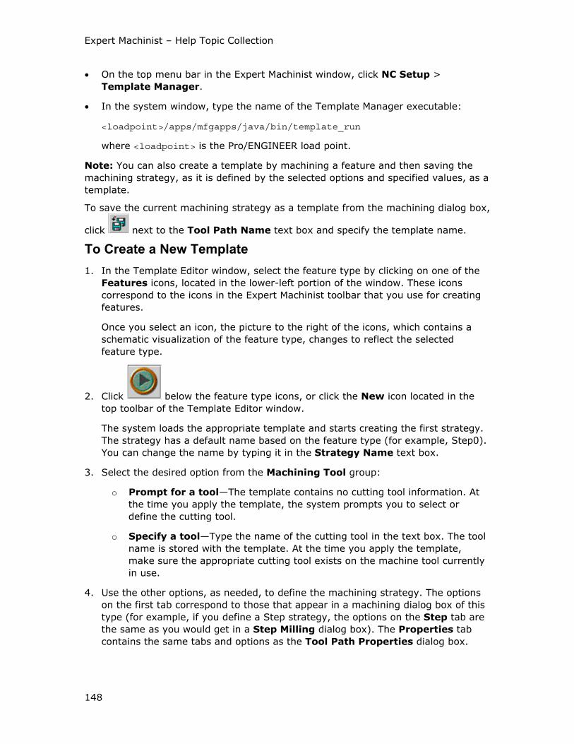
Expert Machinist – Help Topic Collection
148
• On the top menu bar in the Expert Machinist window, click NC Setup >
Template Manager.
• In the system window, type the name of the Template Manager executable:
<loadpoint>/apps/mfgapps/java/bin/template_run
where <loadpoint> is the Pro/ENGINEER load point.
Note: You can also create a template by machining a feature and then saving the
machining strategy, as it is defined by the selected options and specified values, as a
template.
To save the current machining strategy as a template from the machining dialog box,
click next to the Tool Path Name text box and specify the template name.
To Create a New Template
1. In the Template Editor window, select the feature type by clicking on one of the
Features icons, located in the lower-left portion of the window. These icons
correspond to the icons in the Expert Machinist toolbar that you use for creating
features.
Once you select an icon, the picture to the right of the icons, which contains a
schematic visualization of the feature type, changes to reflect the selected
feature type.
2. Click below the feature type icons, or click the New icon located in the
top toolbar of the Template Editor window.
The system loads the appropriate template and starts creating the first strategy.
The strategy has a default name based on the feature type (for example, Step0).
You can change the name by typing it in the Strategy Name text box.
3. Select the desired option from the Machining Tool group:
o Prompt for a tool—The template contains no cutting tool information. At
the time you apply the template, the system prompts you to select or
define the cutting tool.
o Specify a tool—Type the name of the cutting tool in the text box. The tool
name is stored with the template. At the time you apply the template,
make sure the appropriate cutting tool exists on the machine tool currently
in use.
4. Use the other options, as needed, to define the machining strategy. The options
on the first tab correspond to those that appear in a machining dialog box of this
type (for example, if you define a Step strategy, the options on the Step tab are
the same as you would get in a Step Milling dialog box). The Properties tab
contains the same tabs and options as the Tool Path Properties dialog box.

Using Additional Modules
149
5. Once a machining strategy is defined, you can add another strategy to the same
template. This way, you can, for example, define a rough milling and a finish
milling strategy within the same template. When you apply a template with more
than one strategy, the system creates the appropriate number of tool paths. To
add a new strategy to the template, click Edit > New Strategy. Then define the
new strategy as described above.
6. When finished defining the machining strategies, save the template by clicking
File > Save. This will save the template with a .tpl extension.
Note: The name of a .tpl file can not be longer than 31 characters and must all
be lowercase. You can specify a default directory for storing .tpl files by setting
the configuration option mfg_template_dir.
7. Click in the lower-left corner of the dialog box to return to the main page
of the Template Editor dialog box and define another template, for a different
type of feature.
8. To exit the Template Editor, click File > Exit.
To Convert an Existing TPL Template File to XML Format
The template files are currently saved in the XML format. In Beta version, templates
were saved in the TPL format. Currently, both formats are supported within the
Expert Machinist. However, if you created some templates in Beta version and want
to save them for future use, it is recommended that you translate them into the XML
format by following the procedure below.
1. Click File > Translate > TPL To XML.
2. Click … next to the From text box and select the name of the template file in the
browser window. The path and name appear in the From text box.
3. Click … next to the To text box, select the path and type new name of the
template file in the browser window. The path and name appear in the To text
box.
4. Click OK.
The system converts the TPL file to XML format.
To Place a Template
Once you have created a template for a certain feature type, you can machine
features of this type by applying the template. You have to define the feature before
you apply a template to it.
1. On the top menu bar, click NC Create > Tool Paths > Place Template.
The system opens the browser window listing all template files in the directory
specified by the configuration option mfg_template_dir, or, if not set, in the
current directory.
2. Select the template file in the browser window.
Expert Machinist – Help Topic Collection
150
3. Select the feature name in the Select Feature dialog box. As you place the
cursor over a feature name in the dialog box, the appropriate geometry is
highlighted on the screen. Click OK.
4. If the template was created using the Prompt for a tool option, the system
prompts you to select or define a cutting tool.
If the template was created using the Specify a tool option, and the cutting tool
does not exists on the machine tool currently in use, the system issues an error
message and aborts placing the template. Define the appropriate cutting tool and
apply the template again.
Once the template is successfully placed, the system creates the appropriate tool
path and removes the stock material corresponding to the feature geometry.
Miscellaneous
To Manipulate Features Using the Model Tree
You can manipulate existing features, for example, redefine or delete them, directly
from the Model Tree window by using a pop-up menu. For machining features, this
pop-up menu also provides the options of creating a tool path or placing a template;
and for tool paths, the options of displaying the tool path on the screen or outputting
it to a file.
To manipulate a feature from the Model Tree:
1. Select the feature name in the Model Tree window.
If you select a machining feature, the system highlights the feature geometry on
the screen. If you select an operation, the system highlights the geometry of all
the machining features that belong to this operation.
2. Click the right mouse button.
The system opens a pop-up menu. The options in this menu correspond to the
type of selected feature.
3. Select the desired option.
The system starts the appropriate user interface.
Options Available from the Model Tree
When you select a machining feature in the Model Tree window, the system
highlights the feature geometry on the screen. If you select an operation, the system
highlights the geometry of all the machining features that belong to this operation.
Depending on the type of feature selected in the Model Tree, the pop-up menu
contains the following options:
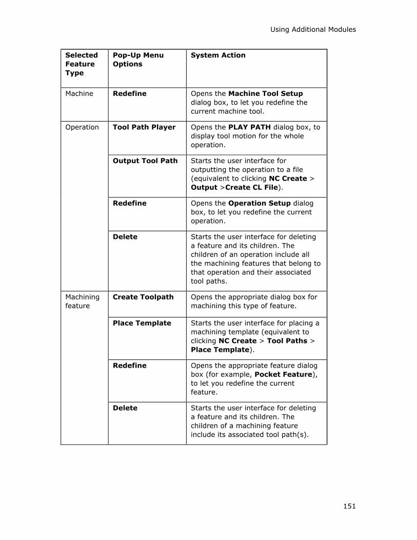
Using Additional Modules
151
Selected
Feature
Type
Pop-Up Menu
Options
System Action
Machine Redefine Opens the Machine Tool Setup
dialog box, to let you redefine the
current machine tool.
Tool Path Player Opens the PLAY PATH dialog box, to
display tool motion for the whole
operation.
Output Tool Path Starts the user interface for
outputting the operation to a file
(equivalent to clicking NC Create >
Output >Create CL File).
Redefine Opens the Operation Setup dialog
box, to let you redefine the current
operation.
Operation
Delete Starts the user interface for deleting
a feature and its children. The
children of an operation include all
the machining features that belong to
that operation and their associated
tool paths.
Create Toolpath Opens the appropriate dialog box for
machining this type of feature.
Place Template Starts the user interface for placing a
machining template (equivalent to
clicking NC Create > Tool Paths >
Place Template).
Redefine Opens the appropriate feature dialog
box (for example, Pocket Feature),
to let you redefine the current
feature.
Machining
feature
Delete Starts the user interface for deleting
a feature and its children. The
children of a machining feature
include its associated tool path(s).
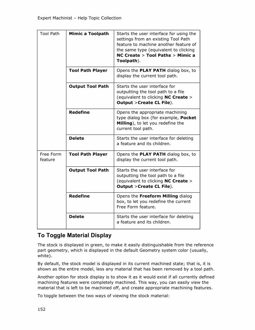
Expert Machinist – Help Topic Collection
152
Mimic a Toolpath Starts the user interface for using the
settings from an existing Tool Path
feature to machine another feature of
the same type (equivalent to clicking
NC Create > Tool Paths > Mimic a
Toolpath).
Tool Path Player Opens the PLAY PATH dialog box, to
display the current tool path.
Output Tool Path Starts the user interface for
outputting the tool path to a file
(equivalent to clicking NC Create >
Output >Create CL File).
Redefine Opens the appropriate machining
type dialog box (for example, Pocket
Milling), to let you redefine the
current tool path.
Tool Path
Delete Starts the user interface for deleting
a feature and its children.
Tool Path Player Opens the PLAY PATH dialog box, to
display the current tool path.
Output Tool Path Starts the user interface for
outputting the tool path to a file
(equivalent to clicking NC Create >
Output >Create CL File).
Redefine Opens the Freeform Milling dialog
box, to let you redefine the current
Free Form feature.
Free Form
feature
Delete Starts the user interface for deleting
a feature and its children.
To Toggle Material Display
The stock is displayed in green, to make it easily distinguishable from the reference
part geometry, which is displayed in the default Geometry system color (usually,
white).
By default, the stock model is displayed in its current machined state; that is, it is
shown as the entire model, less any material that has been removed by a tool path.
Another option for stock display is to show it as it would exist if all currently defined
machining features were completely machined. This way, you can easily view the
material that is left to be machined off, and create appropriate machining features.
To toggle between the two ways of viewing the stock material:
Using Additional Modules
153
1. On the toolbar, click .
The system displays the stock in such a way that only the "extra" material left to
be machined off is shown in green. The system temporarily removes from the
stock model all the material corresponding to the currently defined features.
Whenever the edges of the stock coincide with the edges of the reference model,
they are shown in Geometry color.
2. To toggle back to the all-green stock display, click once more.

155
Index
4
4-axis machining in Expert Machinist
specifying output options ............ 21
specifying rotary clearance.......... 16
specifying rotation axis ............... 21
using long tools ......................... 31
4-axis machining in Expert Machinist
.................................... 16, 21, 31
B
Boss Top
creating.................................... 84
machining................................. 86
Boss Top ................................84, 86
C
Channel
creating.................................... 72
machining................................. 73
Channel..................................72, 73
CL data
deleting a command................. 145
including postprocessor words ... 144
redefining a command .............. 145
saving to file ........................... 146
using parameters..................... 145
CL data ..................................... 144
cutting tools
adding a new tool ...................... 34
bill of materials.......................... 35
deleting .................................... 37
materials setup.......................... 33
modifying..................................37
retrieving ..................................36
saving parameters......................37
setting up..................................31
sketched tools............................36
specifying speeds and feeds.........35
using solid tools ................... 37, 38
using the Chamfering tool..........118
using the Corner Rounding tool ..126
using the Side Mill tool ..............110
cutting tools ......34, 35, 110, 118, 126
E
Entry Hole
creating ..................................135
machining ...............................137
Entry Hole...........................135, 137
Expert Machinist
creating a process ....................... 2
creating an NC Model ................... 3
modal settings ............................ 1
process overview......................... 1
retrieving a process ..................... 2
Expert Machinist ............................ 2
F
Face
creating ....................................50
machining .................................51
Face ...................................... 50, 51
features in Expert Machinist
Expert Machinist – Help Topic Collection
156
additional elements for No Stock
machining .............................. 41
adjusting boundaries .................. 42
adjusting depth ......................... 46
adjusting feature top for No Stock
machining .............................. 46
adjusting Soft Walls ................... 46
Boss Top .................................. 84
Channel.................................... 72
creating.................................... 41
Entry Hole .............................. 135
Face......................................... 50
Flange...................................... 90
Free Form............................... 138
Hole Group ............................. 128
machining................................. 47
O-Ring ..................................... 94
Pocket...................................... 58
Profile ...................................... 69
Program Zero............................ 19
Rib Top..................................... 97
Slab ......................................... 53
Slot.......................................... 77
Step......................................... 65
Through Pocket ......................... 61
Through Slot ............................. 80
Top Chamfer ........................... 113
Top Round .............................. 121
types of machining features ........ 39
Undercut ................................ 104
using the Model Tree ................ 150
features in Expert Machinist41, 46, 58,
80, 94, 97, 104, 113, 121
fixtures
activating ..................................29
creating ....................................27
deleting ....................................30
modifying..................................29
using ........................................30
fixtures.............................27, 29, 30
Flange
creating ....................................90
machining .................................91
Flange ................................... 90, 91
Free Form machining ...................138
H
Hole Group
combining selection methods .....128
creating ..................................128
machining ...............................130
pattern selection ......................129
selecting holes by axes .............129
selecting holes by diameter .......129
selecting holes by feature
parameters ...........................129
selecting holes on a surface .......129
Hole Group..........................128, 130
M
machine tools
creating ....................................20
default post ...............................21
machine tools ......................... 20, 21
machining
Index
157
Boss Top .................................. 86
Channel.................................... 73
Entry Hole .............................. 137
Face......................................... 51
Flange...................................... 91
Free Form............................... 138
Hole Group ............................. 130
mimicking a tool path................. 49
No Stock machining ..................... 3
O-Ring ..................................... 94
Pocket...................................... 58
Profile ...................................... 70
Rib Top................................... 100
saving as template..................... 47
setting Tool Path Properties......... 48
Slab ......................................... 55
Slot.......................................... 78
Step......................................... 66
Through Pocket ......................... 63
Through Slot ............................. 81
Top Chamfer ........................... 116
Top Round .............................. 124
Undercut ................................ 107
using settings for next tool path... 47
using the Model Tree ................ 150
machining 3, 48, 49, 81, 94, 100, 107,
116, 124
N
NC model
creating...................................... 3
creating separately ...................... 5
creating stock ............................. 8
manipulating .............................. 5
No Stock machining ..................... 3
replacing a reference model.......... 6
NC model...................................... 3
No Stock machining
adjusting feature top ..................46
creating features ........................41
creating the NC model ................. 3
No Stock machining............. 3, 41, 46
O
operations
Program Zero ............................19
setup........................................16
operations....................................16
O-Ring
creating ....................................94
machining .................................94
O-Ring.........................................94
P
creating ....................................58
machining .................................58
Pocket .........................................58
PPRINT ........................................24
PPRINT table ................................25
Profile
creating ....................................69
machining .................................70
Profile.................................... 69, 70
Program Zero
Expert Machinist – Help Topic Collection
158
defining .................................... 18
feature level.............................. 19
operation level .......................... 19
z-axis orientation....................... 19
Program Zero............................... 18
R
rapid feed rate
set up ...................................... 21
rapid feed rate ............................. 21
Rib Top
creating.................................... 97
machining............................... 100
Rib Top ................................ 97, 100
S
simulated tool path ..................... 141
Slab
creating.................................... 53
machining................................. 55
Slab.......................................53, 55
Slot
creating.................................... 77
machining................................. 78
Slot .......................................77, 78
Step
creating.................................... 65
machining................................. 66
Step ......................................65, 66
stock
creating...................................... 8
material display ....................... 152
modifying allowances ................. 14
modifying outline .......................15
retrieving ................................... 3
stock ............................................ 8
T
templates
creating ..................................148
placing....................................149
saving.....................................148
saving machining strategy ...........47
Template Manager....................147
using the Model Tree ................150
templates.................... 147, 148, 149
Through Pocket
creating ....................................61
machining .................................63
Through Pocket....................... 61, 63
Through Slot
creating ....................................80
machining .................................81
Through Slot .......................... 80, 81
tool change time ...........................21
tool path
adding break points ..................143
displaying the tool motion .........141
outputting CL data....................146
outputting NC codes .................146
positioning the tool ...................144
saving to file............................146
tool path .............................141, 142
tool travel limits............................21
Top Chamfer
Index
159
creating.................................. 113
machining............................... 116
using the Chamfering tool ......... 118
Top Chamfer ................ 113, 116, 118
Top Round
creating.................................. 121
machining............................... 124
using the Corner Rounding tool.. 126
Top Round .................. 121, 124, 126
U
Undercut
creating ..................................104
machining ...............................107
using the Side Mill tool ..............110
Undercut..................... 104, 107, 110
