experiments on a general thermoacustic
TRANSCRIPT
LIBRARY
RESEARCH REPORTS DIVISION NAVAL POSTGRADUATE SCHOOL MONTEREY, CA 93943-5002
I EXPERIMENTS ON A GENERAL THERMOACOUSTIC ENGINE
Final Report under Grant N00014-89-J-3104
Peter H. Ceperley
Physics Department and
Electrical and Computer Engineering Department George Mason University.
// Fairfax, Virginia 22030
H»V ajSeptember 1992. (revised'7\June 1993)
Final Report 15 July 1989- 14 July 1992
Approved for public release; distribution unlimited.
Prepared for:
THE OFFICE OF NAVAL RESEARCH PHYSICS DIVISION-CODE 1112 ARLINGTON, VA 22217-5000
ftDA %W\

REPORT DOCUMENTATION PAGE form Approved
OMB No 0704-0188
•uoi'c 'Pooling Burden 'or thu collection of ^formation t\ estimated to average • *our oer re*ponve. including the time for reviewing instructions, vearcn.ng enst<ng gttt sources gathering and maintaining the data needed, and completing and reviewing the collection of information Send comments regarding this burden estimate or any other asoect of thii collection of information, including suggestions lor reducing thu Burden to Washington needguarten Service*. Directorate 'or information Operations and »eoon». uis jefferson Oavis Highway. Suite '20* Arlington. VA 1112U3C2 and to me Office of Management and Budget Paperwork Seduction Proiect(0704-oiU). Washington. DC J0S0J
1. AGENCY USE ONLY (leave blink) 2. REPORT OATE 8 Sept 92
3. REPORT TYPE AND DATES COVERED
Final Report, 15.July 89 -14 July 92 4. TITLE ANO SUBTITLE Experiments on a General Thermoacoustic Engine
6. AUTHOR(S)
Ceperley, Peter H.
5 FUNDING NUMBERS PE 61153N G N00014-89-J-3104 TA uri5002
7. PERFORMING ORGANIZATION NAME(S) AND AOORESS(ES) George Mason University Grants Administration Offices 4400 University Drive Fairfax, VA 22030
B. PERFORMING ORGANIZATION REPORT NUMBER
PHC-001
9. SPONSORING/MONITORING AGENCY NAME(S) ANO ADDRESS(ES)
Office of Naval Research Physics Division - Code 1112 Arlington, VA 22217-5000
10. SPONSORING /MONITORING AGENCY REPORT NUMBER
11. SUPPLEMENTARY NOTES
124. DISTRIBUTION / AVAILABILITY STATEMENT
Approved for public release; distribution unlimited
12b. DISTRIBUTION CODE
13. ABSTRACT (Maximum 200 words) Research on thermoacoustic devices has been carried out during the 36 month
period ending 14 July, 1992. In the area of general thermoacoustics: (1) Several different setups were constructed to apply arbitrary sound fields to thermoacoustic structures. (2) Detailed computer modeling of the effect of varying the phase of the acoustic impedance of the sound field has been carried out. (3) A simple equivalent thermodynamic circuit model has been developed and computer tested. (4) These setups were used to measure thermoacoustic properties of various grades of steel wool, filter sand, layered stainless steel, and layered mylar. In the area of acoustic resonators: several rotating wave acoustic resonators were built and tested as means to efficiently apply an arbitrary phased sound field to a thermoacoustic device. Single point excitation of these was achieved. Experiments on an arbitrary phased cryocooler were made.
14. SUBJECT TERMS
rotating waves acoustic loss
thermoacoustics shock formation
cryocooler layered structures
15. NUMBER OF PAGES 18
16. PRICE COOE
17. SECURITY CLASSIFICATION OF REPORT unclassified
18. SECURITY CLASSIFICATION OF THIS PAGE
unclassified
19. SECURITY CLASSIFICATION OF ABSTRACT unclassified
20. LIMITATION OF ABSTRACT
NSN 7540-01-280-5500 Standard Form 298 (Rev 2-89) Prescribed by ANSI Std Z 39 8

TABLE OF CONTENTS
page
LIST OF FIGURES iv
1. INTRODUCTION 1
2. RESEARCH PROJECTS 2
2.1 Development of a Thermoacoustic Simulator Apparatus 2
2.2 Computer Study of the Effect of Phase on Thermoacoustic Devices 4
2.3 Measurements of Properties of Various Thermoacoustic Structures 5
2.4 Development of a Simple Circuit Model for Thermoacoustic Devices 6
2.5 Experiments on Rotating Waves 8
2.6 Development of a Thermoacoustic Cryocooler 10
3. CONTRIBUTIONS TO THE INFRASTRUCTURE AT GEORGE MASON UNIVERSITY 11
4. SUMMARY 11
REFERENCES 12
iii
LIST OF FIGURES
Figure page
1. The three thermoacoustic simulators built and tested. 3
2. Effect of the phase of the impedance of the sound field on the performance of a themoacoustic prime mover. 4
3. Testing of thermoacoustic structures: photo of the end of a layered structure and thermal roll off frequency plotted against flow resistance for various structures measured. 5
4. The simple electrical circuit model for thermoacoutic devices. 6
5. Comparison of results from the circuit model with those from a computer simulation. 7
6. Resonators used in rotating wave experiments. 9
7. Shocking wave front in rotating wave resonator. 9
8. Thermoacoustic cryocooler structure in simulator, as tested. 10
IV
1. INTRODUCTION
The research described in this report was carried out under Grant N00014-89-J-3104, part of the University Research Initiative (uri5002) in the time period 15 July 1989 to 14 July 1992. It had as its goal the investigation of a general class of thermoacoustic devices, of arbitrary phase in the impedance of the sound field. This research was to understand the sensitivities of thermoacoustic devices to this phase, to try to optimize it, and start to experiment with practical devices with optimized phase. Along these lines, we also experimented with resonators capable of efficiently applying such an arbitrary phase to a thermoacoustic structure. Because this grant was part of the University Research Initiative and as such designed to strengthen the teaching and research infrastructure, Section 3 of this report summarizes the infrastructure development resulting from this grant at George Mason University.
The following persons participated in the research:
Graduate students
A. Koren, M.S. student in Applied Physics, graduated Spring 1992, will continue in the new Ph.D. program.
M. Hutchison, M.S. student in Applied Physics, has thesis yet to finish. J. Velazco*, M.S. and Ph.D. student in Electrical and Computer Engineering.
Senior personnel
P. H. Ceperley, Principle Investigator.
"Mr. Velazco received no direct support from the grant. He worked with the P.I. on a spin off of the rotating waves research, a study of rotating waves in electromagnetic applications.

2. RESEARCH PROJECTS
The following research projects were undertaken during the report period:
A. General thermoacoustics:
1. Development of a thermoacoustic simulator apparatus
2. Computer study of the effect of phase on thermoacoustic devices
3. Measurements of properties of various thermoacoustic structures
4. Development of a simple circuit model for thermoacoustic devices
B. Experiments on rotating waves
C. Development of a thermoacoustic cryocooler
2.1 Development of a Thermoacoustic Simulator Apparatus
Figure 1 :>nows the three thermoacoustic simulators built and tested. These devices generated a sound field adjustable both in phase and amplitude for use in testing thermoacoustic, porous structures. The first device1,2, labeled A, was operated in the 0.3 to 70 Hz range and produced pressure amplitudes up to 200 Pa. Its design also included hot and cold heat exchangers to impress a temperature gradient across the thermoacoustic structure and the pressure transducers which were connected to a Keithley 570 data acquisition board and a 386 PC type computer. After preliminary processing, the resulting data was displayed in MathCad for analysis. This simulator was used both to measure thermoacoustic properties of various porous structures and to provide the acoustic and thermal environment to simulate the operation of various thermoacoustic devices. I will discuss the results of such measurements in Section 2.3 and such a simulation in Section 2.6.

Simulation devices B and C were built to provide increased pressure amplitude, up to 11 kPa rms, primarily for use in simulation and development of a thermoacoustic cryocooler. Devices B and C also have the advantage of being an acoustically cleaner system, producing pure plugs of moving gas, while adding the potential problems of leaking and friction associated with pistons.
,va*or COO
Computer (386)
Data aqulsltion unit
nmpu'er controlled oscillator
and soeaker drivers
speaker
heat exchanger
porous structure
piston
-— speaker
piston
pressure transducer
thermocouple
layered mylar structure
insulation
B
Fig. 1. Thermoacoustic simulators.

2.2 Computer Study of the Effects of Phase on Thermoacoustic Devices
The bulk of thermoacoustic devices previously studied use standing wave acoustic fields. Standing waves have a ninety degree phase angle between the pressure and velocity amplitude in the thermoacoustically active structure. The author of this report has long held that traveling acoustic waves, with approximately a zero degree phase angle, would be superior for thermoacoustic applications. Under this grant, a computer study has been made comparing the performance of several thermoacoustic devices as a function of phase. While this calculation uses equations that have been previously derived3, these equations are quite complex and beg for a careful interpretation. Figure 2 shows a typical result* of our studies.
10000
1000 E 51
•g I c c CO
o
100
10
gfflcienctea
-1.5 -1 -0.3
acouMc ptwM (radhna)
10 100
dT/dx (1000 K/m)
1000
1000
Fig. 2. Typical output of a computer study on thermoacoustic devices. The left one shows the lines of constant gain and constant Camot efficiency on a grid of channel width (distance between layers in a layer structure) versus temperature gradient for a traveling wave heat engine. The right one shows the Carnot efficiency and power gain versus phase for various channel widths. Because the right graph has acoustical phase as a variable, it includes the whole range of traveling and standing wave heat engines.

2.3 Measurements of Properties of Thermoacoustic Structures
There are other good methods of measuring physical and acoustic properties of materials such as those discussed by the authors of References 5 and 6, however the thermoacoustic simulators are able to measure these properties in the same acoustic and thermal environment as is encountered in an actual thermoacoustic device, and are able to provide a completely adjustable acoustical field. As we reported in Ref. 7, we used the first thermoacoustic simulator to measure the thermoacoustic properties of the following thermoacoustic structures:
• Various grades of steel wool, parallel and perpendicular orientations, • One grade of filter sand, • One structure made of stainless steel shim stock and stainless steel spacer wires, and • Several structures made of spaced mylar sheets.
The left side of Fig. 3 shows an end view of one of the porous thermoacoustic structures that was fabricated and tested. The right side of Fig. 3 shows a graph of the thermal roll off frequency (the inverse of 2x times the equilibrating time constant) plotted against the flow resistance of these structures. The line indicates the theoretical ratio for parallel plate structures. More work is yet to be done to understand the discrepancy between the theoretical line and the data points in Fig. 3.
Performance of various porous media one atm. air
IOOOO9
N I >. a c V 3
C ? o
1000:
100
10 Row Resistance «V «/«.•)
Fig. 3 Testing of thermoacoustic structures: photo of the end of a layered structure and thermal roll off frequency plotted against flow resistance for various structures measured.

2.4 Development of a Simple Circuit Model
The design of practical devices is usually expedited by the use of simple models which give clear understanding of the design tradeoffs. Figure 4 show a simple electrical circuit model which we have developed under this grant. This circuit models the interaction of acoustical and thermal energies of a small fluid parcel in a thermoacoustic device. It also is useful as an approximation for whole thermoacoutic device, providing parameters such as the absolute temperature and the thermal resistance do not vary excessively in the device. The equivalent or analogous quantities are shown in Table 1.
R
T wai cgas.^
gas
U compression
Fig. 4. Simple electric circuit model for thermoacoustic processes.

TABLE 1.
Equivalent parameters between electrical circuit model and
thermoacoustics
Electric Circuit
Parameter*
Equivalent Thermoacouetic
Paramatara (par m')
•lactnc* currant
voltaga
capacitanca
reaiatance
alact. powar ganaratad
bv voltaga aourca
alact. powar ganaratad
by currant aourca
flow of available work IW/m*
abaoluta tamparatura IK)
conatant preeeure heat capacity
par unit volume U/X-mJ)
tharmal raaiatanca iw/K-m'l
acouatical powar abaorbod
lor ganaratadl (W/m*
tharmal availabla anargy density
expended' IW/ml
'Tha tharmal currant danaity lavaragad ovar an acouatlc cvclal flowing from hot to cold lurnta - W;mJ]
aquala thia tharmal availabla anargy danaity axpandad multiplied by tha abaoluta tamparatura and dividad
by tha tamparatura gradiant IdT/dx).
100 T"
We reported in Ref. 8 a comparison of results obtained from this simple model with those obtained from an exact computer simulation reported in Section 2.2. As shown in Fig. 5, agreement is very good for thermal time constants (for gas in the porous structure to equilibrate with the solid) less than and roughly equal to an acoustic period. Since traveling wave devices are best designed with short time constants, they are well modeled by this simple circuit. Standing wave devices generally have longer time constants and consequendy are not as well modeled by this circuit. Depending on the exact parameters, standing wave devices may require an additional component or two in the model.
< E
2
3 a c 5>
I a
5 > <
100 atm helium traveling wave heat engine, 3O,00OK/m
w=0.1mm, Zo=10, 1000K
10?'
1 exact calculation
circuit moder
0.1-
1000
< E
! c o>
i o £
100
100 1000 frequency (Hz)
10000 10
100 atm helium standing wave heat engine, 3000 K/m
w=0.3mm, Zo=10
* *•" •-»- exact calculation
circuit model—•*• *
10 100 frequency (Hz)
1000
Fig. 5. Comparison of results from the simple electric circuit model with those from a computer simulation.
2.5 Experiments on Rotating Waves
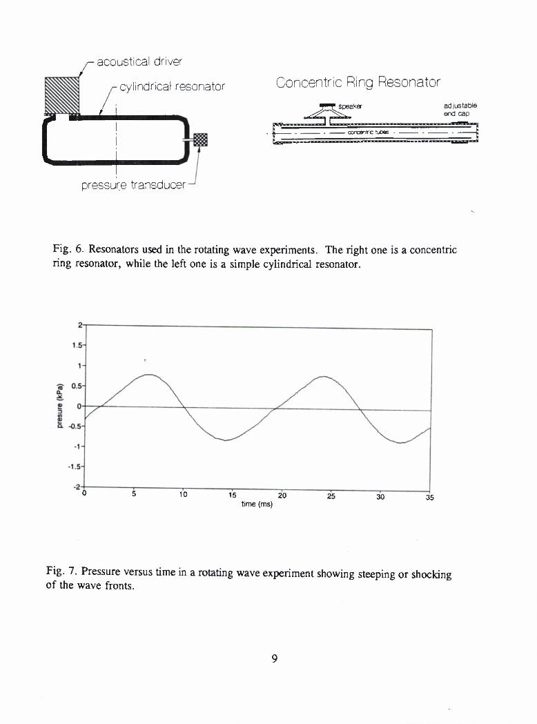
The thermoacoustic simulators discussed above are convenient for providing an acoustic field for thermoacoustic research, however due to the low efficiency of speakers, the simulator would be impractical for use in the operating thermoacoustic device. In that case, the acoustic field would most likely be provided by a suitable resonator. A regular resonator will provide waves with a 90 degree phase angle in the impedance. Rotating waves are required to provide zero phase angle and if mixed with standing waves can alternatively provide an arbitrary phase angle13. Rotating modes can be created by the proper combination of degenerate or nearly degenerate standing wave modes. Our group has been studying rotating waves, both as a general wave phenomena and as applied to thermoacoustic devices. While in some sense rotating waves have been understood for years, the knowledge is not widespread and is usually only mathematical. We feel that rotating waves are best presented in a very mechanistic or visual way as described in Refs. 9 and 10. We have also been experimenting with rotating waves, in the two resonators11 shown in Fig. 6. The first, simple cylindrical resonator labelled A, is of greater interest in general physical acoustics, while the second labelled B is of most interest in thermoacoustic devices. In both, we have observed rotating modes.
We have also experimented and achieved single point excitation13"15 as required for thermoacoustic traveling wave devices. Because a rotating wave is the superposition of two independent standing wave modes, normally two exciting sources are required to create a rotating mode. However with the proper perturbation in the resonator, a single source can suffice11. We have also observed the rotating wave shock formation shown in Fig. 7 at amplitudes greater that 1 kPa, which is an interesting physical acoustics phenomenon in itself. Spiral wave fields were also generated and mapped out12. These are of general interest because they do not propagate along a straight line from source to receiver, even in an isotropic medium. They are the wave type emitted by propellers.
Also as a spin-off of this research, is the work by J. Velazco and the author in the area of rotating waves in electromagnetic microwave cavities and their applications16.
8
acoustical driver
cylindrical resonator Concentric Ring Resonator
pressure transducer
speaker adjustable end cap
concentre tuOes
Fig. 6. Resonators used in the rotating wave experiments. The right one is a concentric ring resonator, while the left one is a simple cylindrical resonator.
10 15 20 time (ms)
25 30 35
Fig. 7. Pressure versus time in a rotating wave experiment showing steeping or shocking of the wave fronts.
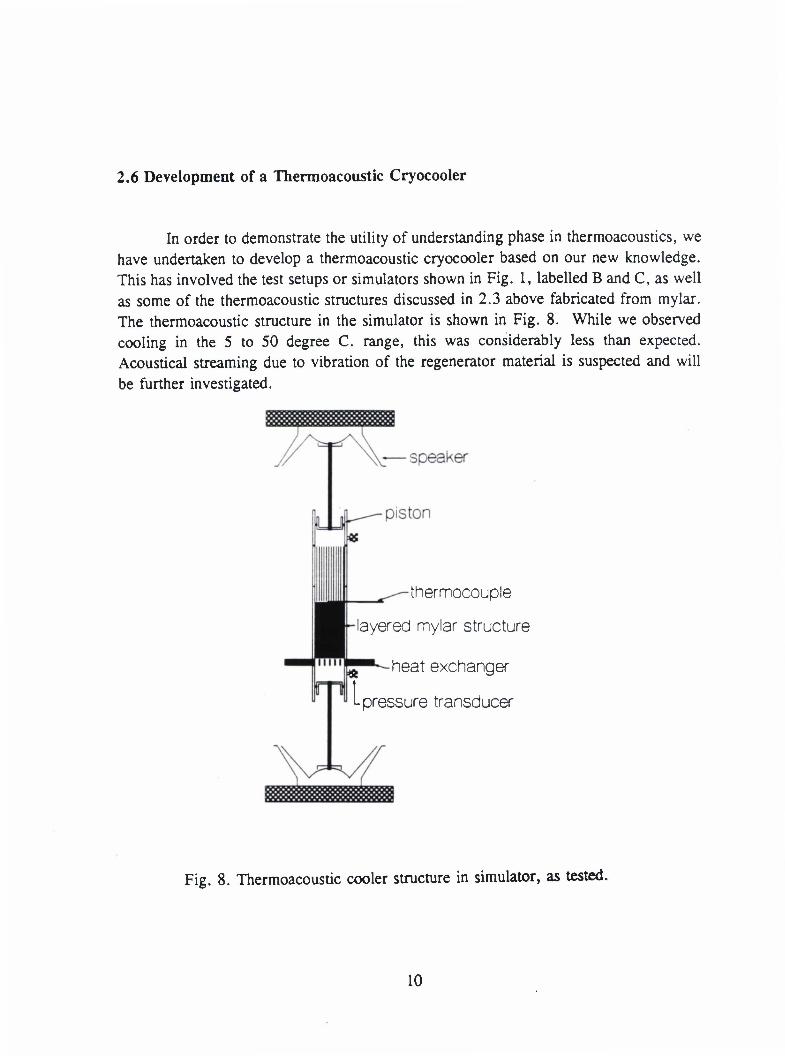
2.6 Development of a Thermoacoustic Cryocooler
In order to demonstrate the utility of understanding phase in thermoacoustics, we have undertaken to develop a thermoacoustic cryocooler based on our new knowledge. This has involved the test setups or simulators shown in Fig. 1, labelled B and C, as well as some of the thermoacoustic structures discussed in 2.3 above fabricated from mylar. The thermoacoustic structure in the simulator is shown in Fig. 8. While we observed cooling in the 5 to 50 degree C. range, this was considerably less than expected. Acoustical streaming due to vibration of the regenerator material is suspected and will be further investigated.
thermocouple
layered mylar structure
^••--heat exchanger
"-pressure transducer
Fig. 8. Thermoacoustic cooler structure in simulator, as tested.
10

CONTRIBUTIONS TO THE INFRASTRUCTURE AT GEORGE MASON UNIVERSITY
One of the benefits of this research for both the DoD and the public is that it has materially reinforced the teaching and research infrastructure of a developing university. George Mason University was started only a few decades ago and is one of the few relatively young state universities in our country. It has only recently been developing graduate programs. This grant has assisted that development by paying for the development of a physical acoustics laboratory associated with both the Department of Electrical and Computer Engineering and the Physics Department. It furthermore has supported the principle investigator and his students to do research in physical acoustics. It has also, in part, helped to make possible the launching of a new Ph.D. program at this school in the area of Computational Science with a strong emphasis in Computational Physics. Because this university is located Fairfax County, Virginia (a major part of the Washington D.C. suburbs) and therefore is very close to many Naval and DoD facilities, these new educational and research facilities are available to and will serve Naval and DoD personnel. The principle investigator, as well as the other faculty have students who are employed by the Navy (at NRL and David Taylor, for example) as well as by the other armed forces.
Reference 17 discusses color visualization of wave and fields surfaces done at George Mason University. The grant made possible the purchase of the Hewlett Packard color desk jet printer used for this work.
11
4. SUMMARY
Research during the time 15 July 1989 to 14 July 1992 has been directed towards developing improved thermoacoustic heat engines, utilizing optimal phasing in the impedance of the sound field. More specifically, thermoacoustic simulators were designed and built to allow testing of thermoacoustic structures. A computer simulation of thermoacoustic devices was made to study the sensitivity to phase in several representative thermoacoustic devices. The thermoacoustic properties of a number porous structures were measured, including ones made of steel wool, sand, layered stainless steel, and layered mylar. A simple equivalent circuit for thermoacoustic devices was developed and verified with computer simulation. Rotating waves were explored as means to efficiently create the arbitrary phased sound field in a thermoacoustic device. Rotating acoustical waves in cylindrical and ring resonators were experimentally observed. Single point excitation was achieved in both, as well as observation of acoustical shocking in one of the resonators. Spiral wave fields were also explored. Finally, a thermoacoustic cryocooler was built and tested under various phases of the sound field impedance.
12

REFERENCES
1. Peter H. Ceperley, "Measurements on a general thermoacoustic heat engine," Paper JJ3, 119th Meeting, Acoustical Society of America, Penn State, 21-25 May 1990. ABSTRACT: J. Acoust. Soc. Am. 87, S85 (1990).
2. Peter Ceperley, "Phase and impedance dependence of gains and losses in a thermoacoustic device," Paper S95, 120th Meeting, Acoustical Society of America, San Diego, 26-30 November 1990. ABSTRACT: J. Acoust. Soc. Am. 88, S95 (1990).
3. G. W. Swift, "Thermoacoustic engines," /. Acoust. Soc. Am. 84, 1145-1180 (1988).
4. Peter H. Ceperley, "The question of phase in thermoacoustic devices", in preparation.
5. Heui-Seol Roh, W. Patrick Arnott, and James M. Sabatier, "Measurement and calculation of acoustic propagation constants in arrays of small air-filled rectangular tubes," J. Acoust. Soc. Am. 89, 2617-2624 (1991).
6. Anthony A. Atchely, Thomas H. Hofler, Michael L. Muzzerall, M. David Kite, and Chianing Ao, "Acoustically generated temperature gradients in short plates", J. Acoust. Soc. Am. 88, 251-263 (1990).
7. Alon Koren and Peter H. Ceperley, "Thermoacoustic properties of porous media," Paper 9PA7, 121th Meeting, Acoustical Society of America, Baltimore, 29 April-3 May 1991. ABSTRACT: J. Acoust. Soc. Am. 89, 2007 (1991).
8. Peter H. Ceperley, HA simple circuit model for the thermodynamics of thermoacoustic devices," Paper 9PA6, 121th Meeting, Acoustical Society of America, Baltimore, 29 April-3 May 1991. ABSTRACT: J. Acoust. Soc. Am. 89, (1991).
9. Peter H. Ceperley, "Rotating waves," American Journal of Physics 60, 938-942 (1992).
13
10. P. H. Ceperley and A. Koren, "Demonstration of rotating wave fields on the surface of water," Paper 162, 1992 Joint American Physical Society/American Association of Physics Teachers April Meeting, 20-24 April 1992, Washington, D.C. ABSTRACT: Announcer (AAPT), 22, 41 (1992).
11. Alon Koren and Peter H. Ceperley, "Observation of single-point excitation and shocking of rotating acoustic waves," Paper 2PA8, 123rd Meeting of the Acoustical Society of America, Salt Lake City, 11-15 May 1992. ABSTRACT: J. Acoust. Soc. Am. 91, 2331 (1992).
12. Peter H. Ceperley and Alon Koren, "Acoustic spiral wave field", Paper lpPA14, 125 th Meeting of the Acoustical Society of America, Ottawa, Canada, 17-21 May 1993. ABSTRACT: J. Acoust. Soc. Am. 93, 2278 (1993).
13. Peter H. Ceperley, "Split mode traveling wave ring-resonator", U. S. Patent 4,686,407 (1987).
14. Minoru Kurosawa and Sadayuki Ueha, "Single-phase drive of a circular ultrasonic motor", J. Acoust. Soc. Am. 90, 1723-1728 (1991).
15. Peter H. Ceperley, "Comments on single phase drive of a circular ultrasonic motor", J. Acoust. Soc. Am. 92, 1167 (1992).
16. Jose E. Velazco and Peter H. Ceperley, "A discussion of rotating wave fields for microwave applications," to be published in Feb. 1993 issue of IEEE Transactions on Microwave Theory and Techniques.
17. Peter H. Ceperley, "Low-Cost System Plots Fields and Waves in Color", Computers in Physics, 7, 274-279 (May/June 1993).
14