experimental study on performance of ieee 802.11n and ... · experimental study on performance of...
TRANSCRIPT

Experimental Study on Performance of IEEE 802.11n andImpact of Interferers on the 2.4 GHz ISM Band
Sandra Fiehe, Janne Riihijärvi and Petri MähönenInstitute for Networked Systems, RWTH Aachen University
Kackertstrasse 9, D-52072 Aachen, Germanyemail: {sfe, jar, pma}@inets.rwth-aachen.de
ABSTRACTWe have studied the performance of IEEE 802.11n in exten-sive measurement campaigns carried out in both interference-controlled and typical office environments. The results showthat in a typical office environment significant performanceimprovement compared to earlier IEEE 802.11 technologiescan be expected, but theoretically achievable bitrates werenot reached. We also studied the sensitivity of IEEE 802.11nperformance to interference from other technologies used inthe 2.4 GHz ISM band, and found that 802.11n in generaltolerates interference well. However, the results also showthat a powerful enough narrowband interferer can have asignificant negative impact and legacy 802.11 technologiesoperating in same region will cause performance degrada-tion. The results on interference susceptibility and key roleof channel bonding in the increase of throughput indicatethat in new IEEE 802.11n deployments the 5 GHz ISM bandshould be preferred to the 2.4 GHz ISM band.
Categories and Subject DescriptorsC.4 [Performance of Systems]: Performance Attributes;C.2.1 [Network Architecture and Design]: Wireless Com-munication
General TermsExperimentation, Measurement, Performance
KeywordsIEEE 802.11n, performance measurements, interference
1. INTRODUCTIONWireless local area networks have become one of the most
common ways to connect portable devices to the Internet.Recently significant development effort has been placed onthe most recent edition of IEEE 802.11 or “Wi-Fi” technolo-gies, namely on IEEE 802.11n [4]. The main objective of
Permission to make digital or hard copies of all or part of this work forpersonal or classroom use is granted without fee provided that copies arenot made or distributed for profit or commercial advantage and that copiesbear this notice and the full citation on the first page. To copy otherwise, torepublish, to post on servers or to redistribute to lists, requires prior specificpermission and/or a fee.IWCMC’10, June 28–July 2, 2010, Caen, France.Copyright 2010 ACM 978-1-4503-0062-9/10/06/ ...$10.00.
the IEEE 802.11n design work has been to increase the ca-pacity of the system compared to widely used IEEE 802.11aand 802.11b/g networks [2, 3, 1]. This has been achievedby several enhancements of the physical and link layer de-signs compared to earlier standards, most notably by in-cluding support for higher bandwidths and multiple antenna(MIMO) technologies. The basic principles of earlier IEEE802.11 designs have not been changed, however, and IEEE802.11n is still a CSMA-based system operating on the 2.4GHz and 5 GHz ISM bands. Because of this, good coexis-tence properties with legacy 802.11 systems and other ISMband technologies will be key to widespread acceptance andsuccess of 802.11n.
Throughout the standardisation process products basedon draft versions of the standard have become available froma variety of manufacturers. It has been recently confirmedthat the majority of these products, namely those based ondraft 2.0 or later of the 802.11n standard will pass Wi-FiAlliance certification, and are thus expected to remain com-monplace in the coming years. Despite this relatively fewstudies have been conducted on the performance achieved bythese products and their interference susceptibility and coex-istence properties with other ISM-band technologies. Whileseveral theoretical and simulation studies are available (see,for example, [8] and references therein), only few empiricalstudies have appeared. The most extensive study on 802.11nperformance in the literature is currently [10], in which theauthors observed significant sensitivity to interference fromlegacy 802.11 devices, and overall performance significantlybelow theoretical expectations. Impact of 802.11n on otherISM band technologies has also been studied, see [7] for anexample. In this paper we report on our results from a thor-ough measurement campaign we have conducted to evaluatethe performance of some of the available 802.11n products,and how sensitive that performance is on interference andthe propagation environment. Compared to earlier workwe systematically study the influence different types of in-terferers have on 802.11n performance, and also performedmeasurements in an isolated chamber to ensure that no un-controlled interference would influence the results.
The rest of the paper is structured as follows. In SectionII we give a short overview of the 802.11n design, highlight-ing some of the key differences to earlier 802.11 standards.In Section III the measurement environments and the equip-ment used are described, after which the obtained results arepresented and discussed in Section IV. Finally, conclusionsare drawn in Section V.
47

2. OVERVIEW OF THE IEEE 802.11N EN-HANCEMENTS
Like its predecessors 802.11a and 802.11g, 802.11n is basedon an Orthogonal Frequency Division Multiplexing (OFDM)physical layer (PHY). However, as a key difference 802.11nadds multiple-input multiple-output (MIMO) functionalityto the PHY with support for up to four spatial streams.Additionally, an option for using wider bandwidth, namely40 MHz instead of baseline 20MHz has been added. This iscommonly called channel bonding in the literature. Smallerenhancements to the PHY include increasing the numberof OFDM subcarriers used for transmitting user data from48 to 52 in the 20 MHz bandwidth case, adding an option ofreducing the guard interval, and an option of 5/6 coding rateas opposed to a maximum of 3/4 in earlier standards. Thenet effect of these enhancements is to increase the maximumachievable PHY layer bitrate from 54 Mbps of 802.11a/g to600 Mbps. However, at present the most common MIMOconfigurations in available products support only two spatialstreams instead of the full four, in which case the maximumachievable bitrate would drop to 300Mbps, still almost six-fold potential improvement compared to legacy systems.
The 802.11n standard also introduces enhancements tothe link layer. The basic operation is still that of CSMA/CAwith optional RTS/CTS handshake, and the possibility touse the Point Coordination Function (PCF) for contentionfree operation has been retained in the standard (albeit ex-pected to remain almost unused as has been the case untilnow). However, 802.11n also adds support for shorter inter-frame spaces as well as for frame aggregation with block ac-knowledgments. The latter additions allow multiple framesto be transmitted and acknowledged over a single channel ac-cess turn, reducing the overhead induced by the CSMA/CAprotocol. Finally, a power save protocol has been added toimprove energy efficiency of the 802.11n wireless interfaceespecially for handsets and portable computers.
3. MEASUREMENT SETUPWe shall now describe the measurements reported on in
this paper, and the equipment used in those measurements.All measurements were carried out in infrastructure mode.A single UDP connection was used between a computerequipped with an Asus WL-130N PCI card based on theRalink chipset RT 2860 and another computer connected toa Netgear WNRT3500 access point through a gigabit Ether-net connection. The PCI card was connected to an externalantenna with the option of adding attenuators to study theinfluence of received signal strength in a controlled manner.To generate continuous UDP traffic for the measurements,the Iperf traffic generator [9] was used. In order to get reli-able per-packet information (including control frames, num-ber of corrupt frames, precise timestamps, and the actualmodulation and coding scheme used) an additional laptopequipped with the AirPcap N capture card [5] based on theAtheros AR5008 chipset was always placed near the receiver.Packet-level data was collected using the Wireshark proto-col analyser [6], and exported to Matlab for analysis. In allmeasurements channel bandwidth of 40 MHz was used andthe MIMO configuration was that of 2× 3 with two spatialstreams. Frame aggregation for up to eight kilobytes wasenabled, no encryption was used, and UDP datagram sizewas set to 1460 bytes throughout the measurements.
Figure 1: Illustration of the measurement setupused in the anechoic chamber.
Measurements were carried out in two different environ-ments. First, to establish a baseline for the performancewithout heavy effects from the use of MIMO, which dependsignificantly on the propagation environment, and withoutuncontrollable interference from other wireless devices ananechoic chamber was used. The measurement scenario isdepicted in Figure 1. The distance between the sender andthe receiver was approximately 7m, and two locations wereused for placing devices for interference generation. Inter-ference was supplied either by an Agilent signal generator(E4438C) with the three configurations used shown in Fig-ure 2, or by two 802.11b/g equipped laptops sending anIperf-generated UDP traffic stream of a specified averagebitrate between them.
In order to study the performance of 802.11n in an envi-ronment similar to the expected deployments, a typical officeenvironment in a university building was used as a secondmeasurement environment. We shall focus here on resultsobtained with the measurement configurations shown in Fig-ure 3. The position R denotes the location of the receiverand capture device, while S1 and S2 were used as positions ofthe sender. The Wireless LAN interferers (IEEE 802.11b/gdevices) were placed around the sender (S2 or S1) or de-pending on the setup around the receiver with a distance ofabout 1 m.
For each collection of parameter settings a measurementrun of one minute was performed. The results reported be-low are either values aggregated over the entire measure-ment period in which case mean and standard deviationare shown, or functions of the quantity of interest (such asthroughput) over time in which case averaging over 100msperiods is used.
4. RESULTSWe shall begin with results obtained in the anechoic cham-
ber. Figure 4 shows the throughput of the UDP stream aswell as the bitrates of control traffic in case no interferenceand no attenuation is used. The mean throughput measuredwas 161.61 Mbps with packet error rate of under 0.01%.These figures give an indication of the best achievable per-formance with the equipment used in the almost completeabsence of MIMO gain. We believe such asymptotic resultsto be of significant interest in studying the expected perfor-mance of the system at extreme operating points, althoughstill rarely obtained in systems-level measurement studies.
Figure 5 illustrates how increasing attenuation influencesthe performance of the system. In the unattenuated case dis-cussed above received signal strengths for the three receiver
48
2.427 2.447 2.467−120
−110
−100
−90
−80
−70
−60
−50
−40
Frequency [GHz]
Sig
nal l
evel
[dB
m]
(a) 4 Mcps, 4 MHz bandwidth
2.427 2.447 2.467−120
−110
−100
−90
−80
−70
−60
−50
−40
Frequency [GHz]
Sig
nal l
evel
[dB
m]
(b) 22 Mcps, 22 MHz bandwidth
2.427 2.447 2.467−110
−100
−90
−80
−70
−60
−50
−40
Frequency [GHz]
Sig
nal l
evel
[dB
m]
(c) 50 Mcps, 48 MHz bandwidth
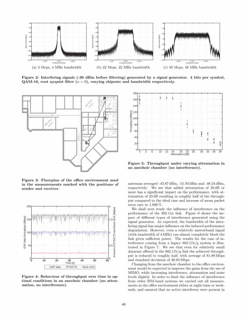
Figure 2: Interfering signals (-30 dBm before filtering) generated by a signal generator. 4 bits per symbol,QAM-16, root nyquist filter (α = 0), varying chiprate and bandwidth respectively.
Figure 3: Floorplan of the office environment usedin the measurements marked with the positions ofsender and receiver.
0 10 20 30 40 50 600
50
100
150
200
UD
P d
ata
thro
ughp
ut [M
bps]
0 10 20 30 40 50 600
0.5
1
1.5
2
Time [s]
Am
ount
of R
TS
/CT
S a
nd b
lock
AC
K [M
bps]
UDP data RTS/CTS block ACK
Figure 4: Behaviour of throughput over time in op-timal conditions in an anechoic chamber (no atten-uation, no interference).
0 3 6 10 13 16 20 23 26 30 33 36 390
20
40
60
80
100
120
140
160
180
Attenuation [dB]
Thr
ough
put [
Mbp
s]
Figure 5: Throughput under varying attenuation inan anechoic chamber (no interference).
antennas averaged -43.87 dBm, -51.93 dBm and -48.24 dBm,respectively. We see that added attenuation of 20 dB ormore has a significant impact on the performance, with at-tenuation of 23 dB resulting in roughly half of the through-put compared to the ideal case and increase of mean packeterror rate to 1.098 %.
We shall next study the influence of interference on theperformance of the 802.11n link. Figure 6 shows the im-pact of different types of interference generated using thesignal generator. As expected, the bandwidth of the inter-fering signal has major influence on the induced performancedegradation. However, even a relatively narrowband signal(with bandwidth of 4MHz) can almost completely block thelink given sufficient power. The results for the case of in-terference coming from a legacy 802.11b/g system is illus-trated in Figure 7. We see that even for relatively smalldatarate offered in the 802.11b/g link the achieved through-put is reduced to roughly half, with average of 81.89 Mbpsand standard deviation of 30.94 Mbps.
Changing from the anechoic chamber to the office environ-ment would be expected to improve the gains from the use ofMIMO, while increasing interference, attenuation and noiselevels slightly. In order to limit the influence of interferencefrom other ISM-band systems we carried out all measure-ments in the office environment either at night-time or week-ends, and ensured that no active interferers were present in
49

−65 −60 −55 −50 −45 −400
20
40
60
80
100
120
140
160
180
Power of interferer [dBm]
Thr
ough
put [
Mbp
s]
4 MHz 22 MHz (fc = 2.457 GHz) 48 MHz (fc = 2.447 GHz)
Figure 6: Throughput of IEEE 802.11n in anechoicchamber with signal generator placed close to thereceiver.
0 10 20 30 40 50 600
50
100
150
200
UD
P d
ata
thro
ughp
ut [M
bps]
0 10 20 30 40 50 600
0.5
1
1.5
2
Time [s]
Am
ount
of R
TS
/CT
S a
nd b
lock
AC
K [M
bps]
UDP data RTS/CTS block ACK
Figure 7: Throughput of IEEE 802.11n with WLANinterference at receiver (IEEE 802.11b/g, 4 MbpsUDP traffic).
0 10 20 30 40 50 600
50
100
150
200
UD
P d
ata
thro
ughp
ut [M
bps]
0 10 20 30 40 50 600
0.5
1
1.5
2
Time [s]
Am
ount
of R
TS
/CT
S a
nd b
lock
AC
K [M
bps]
UDP data RTS/CTS block ACK
Figure 8: Achieved throughput in the office environ-ment with a distance of 7.5 m between sender andreceiver (no additional attenuation, no added con-trollable interference).
0 10 20 30 40 50 600
50
100
150
200
UD
P d
ata
thro
ughp
ut [M
bps]
0 10 20 30 40 50 600
0.5
1
1.5
2
Time [s]
Am
ount
of R
TS
/CT
S a
nd b
lock
AC
K [M
bps]
UDP data RTS/CTS block ACK
Figure 9: Achieved throughput in the office environ-ment with a distance of 18 m between sender andreceiver (no additional attenuation, no added con-trollable interference).
0 3 6 10 13 16 20 23 26 30 33 36 390
20
40
60
80
100
120
140
160
180
Attenuation [dB]
Thr
ough
put [
Mbp
s]
office environment anechoic chamber
Figure 10: Performance under varying attenuationin the office environment with a distance of 7.5 mbetween sender and receiver.
the same floor as the measurement setup. Nevertheless, asshown in Figure 8 the performance obtained falls signifi-cantly short of the theoretical maximum already with onesoft-partition wall between the sender and the receiver. Themeasured throughput in this case averaged at 132.39 Mbpswith standard deviation of 12.90 Mbps. Increasing the dis-tance between the sender and the receiver causes further re-duction of the throughput quite rapidly as seen in Figure 9.Nevertheless, in each case the IEEE 802.11n link offers supe-rior performance to 802.11g, even when taking into accounteffects of wider bandwidth alone.
Figure 10 shows the effects of further attenuation in theoffice environment with shorter link distance, compared tothe results obtained in the anechoic chamber. We see thatdue to the attenuation caused by the soft partition wall,any additional attenuation has rather significant degradingeffect on the obtained throughput. Finally, Figure 11 showsthe impact of 802.11g interferer on the IEEE 802.11n link inthe case of the shorter distance between the sender and thereceiver. Two different generation rates were used for the
50

0 4 1640
60
80
100
120
140
160
Interference by IEEE 802.11b/g WLAN [Mbps]
UD
P T
hrou
ghpu
t of I
EE
E 8
02.1
1n W
LAN
[Mbp
s]
Interference near sender Interference near receiver
Figure 11: Performance under interference from a802.11g WLAN with with a distance of 7.5 m be-tween sender and receiver.
interfering traffic, and two different locations for used forthe interfering link. Increase in the intensity of the inter-fering traffic rapidly reduces the obtained throughput, butperformance remains better than what would be achievablewith legacy technologies in similar conditions.
5. CONCLUSIONSIn this paper we reported on measurements of IEEE 802.11n
performance in various conditions, especially focussing onimpact of interference and changes in propagation condi-tions. The results obtained vary. While the enhancementsin IEEE 802.11n clearly result in better performance com-pared to earlier Wireless LAN technologies, the results aresignificantly lower than the theoretical maxima. In partic-ular the gains from the use of MIMO do not seem as largeas theoretical estimates would indicate, and the majority ofthroughput gain would appear to arise from higher band-width and other physical and link layer enhancements. Thissituation can change, however, as algorithms related to theMIMO functionality used in the chipsets gain maturity.
The results indicate that IEEE 802.11n is fairly tolerantespecially to narrowband interference, but also that even asingle narrowband interferer of sufficient power can causesignificant throughput reduction. Also interference from al-ready deployed IEEE 802.11g systems is an issue that shouldbe carefully considered. We have seen that already a singleactive IEEE 802.11g link can significantly reduce the per-formance of the IEEE 802.11n network, and given the widebandwidth of 802.11n using channel bonding, the number ofinterferers can potentially be large. These results on inter-ference susceptibility and the key role of channel bondingin the increase of throughput indicate that in new IEEE802.11n deployments the 5GHz ISM band should be pre-ferred, provided that the support in the client device side ispresent for this. Frequency planning is also very challengingin the 2.4 GHz band if channel bonding is used since anytwo IEEE 802.11n systems will overlap somewhat in termsof their frequency use. This would undoubtedly reduce theoverall capacity of the system in dense deployments.
AcknowledgmentThe authors would like to thank the RWTH Aachen Univer-sity and the German Research Foundation (Deutsche Forschungs-gemeinschaft, DFG) for providing financial support throughthe UMIC research center. We would also like to thank theEuropean Union for providing partial funding of this workthrough the ARAGORN and FARAMIR projects.
6. REFERENCES[1] Supplement to IEEE Standard for Information
Technology - Telecommunications and InformationExchange between Systems - Local and MetropolitanArea Networks - Specific Requirements. Part 11:Wireless LAN Medium Access Control (MAC) andPhysical Layer (PHY) Specifications: High-SpeedPhysical Layer in the 5GHz band. IEEE Std802.11a-1999, 1999.
[2] Supplement to IEEE Standard for InformationTechnology - Telecommunications and InformationExchange between Systems - Local and MetropolitanArea Networks - Specific Requirements. Part 11:Wireless LAN Medium Access Control (MAC) andPhysical Layer (PHY) Specifications: Higher-SpeedPhysical Layer Extension in the 2.4 GHz band. IEEEStd 802.11b-1999, 2000.
[3] IEEE Standard for Information Technology -Telecommunications and Information Exchangebetween Systems - Local and Metropolitan AreaNetworks - Specific Requirements. Part 11: WirelessLAN Medium Access Control (MAC) and PhysicalLayer (PHY) Specifications. Amendment 4: FurtherHigher Data Rate Extension in the 2.4 GHz band.ISO/IEC 8802-11:2005/Amd.4:2006(E) IEEE Std802.11g-2003 (Amendment to IEEE Std 802.11-1999),2006.
[4] IEEE 802.11n-2009: Standard for InformationTechnology - Telecommunications and InformationExchange between Systems - Local and MetropolitanArea Networks - Specific Requirements. Part 11:Wireless LAN Medium Access Control (MAC) andPhysical Layer (PHY) Specifications. Amendment 4:Enhancements for Higher Throughput. IEEE StdP802.11n, October 2009.
[5] CACE Technologies. AirPcap N, 2009. http://www.cacetech.com/products/airpcap_nx.html
[Last visited: 28/09/2009].
[6] U. Lamping and E. Warnicke. Wireshark User’sGuide. Wireshark Foundation, 2008.
[7] M. Petrova et al. Interference Measurements onPerformance Degradation between Colocated IEEE802.11 g/n and IEEE 802.15. 4 Networks. In Proc. ofICN’07. IEEE Computer Society Washington, DC,USA, 2007.
[8] T. Paul and T. Ogunfunmi. Wireless lan comes of age:Understanding the ieee 802.11n amendment. Circuitsand Systems Magazine, IEEE, 8(1):28–54, Quarter2008.
[9] A. Tirumala, L. Cottrell, and T. Dunigan. Measuringend-to-end bandwidth with Iperf using Web100.
[10] V. Shrivastava et al. 802.11n under the microscope. InProc. of IMC ’08, pages 105–110, New York, NY,USA, 2008. ACM.
51