experimental study of the mixing of two impinging pressure-swirl sprays in crossflow
TRANSCRIPT
Experimental Thermal and Fluid Science xxx (2013) xxx–xxx
Contents lists available at SciVerse ScienceDirect
Experimental Thermal and Fluid Science
journal homepage: www.elsevier .com/locate /et fs
Experimental study of the mixing of two impinging pressure-swirlsprays in crossflow
0894-1777/$ - see front matter � 2013 Elsevier Inc. All rights reserved.http://dx.doi.org/10.1016/j.expthermflusci.2013.04.002
⇑ Corresponding author.E-mail address: [email protected] (B. Bai).
Please cite this article in press as: H. Zhang et al., Experimental study of the mixing of two impinging pressure-swirl sprays in crossflow, Exp. ThermSci. (2013), http://dx.doi.org/10.1016/j.expthermflusci.2013.04.002
Haibin Zhang a,b, Bofeng Bai a,⇑, Li Liu a, Huijuan Sun a, Junjie Yan a
a State Key Laboratory of Multiphase Flow in Power Engineering, Xi’an Jiaotong University, Xi’an 710049, Chinab School of Chemical Engineering and Technology, Xi’an Jiaotong University, Xi’an 710049, China
a r t i c l e i n f o a b s t r a c t
Article history:Received 10 March 2012Received in revised form 26 February 2013Accepted 2 April 2013Available online xxxx
Keywords:Pressure-swirl sprayCrossflowCoherent structureMixing
This paper discusses the results from an experimental study on the mixing of two impinging pressure-swirl sprays in the crossflow with the PIV visualization system and the image-processing techniques.The experiments were carried out inside a rectangular duct (95 mm � 95 mm) at the ambient tempera-ture and pressure. Five injection angles (a = 60–120�, at 15� intervals from the negative direction of thecrossflow) were experimented with the crossflow velocity range from Re = 25,700 to Re = 64,300. Thedroplet dispersion and its dependence on the spray injection angle and the crossflow velocity are exam-ined. The large-scale vortex structures occurred are analyzed and their influence on the mean velocity,vorticity and turbulent characteristics of the droplet swarm are studied. The comparison is made withsingle-spray data of the previous studies. Double coherent structures are discovered and they greatlydepend on the spray injection angle as that of single nozzle. When a < 90�, the greater coherent structuresoccur and the droplet swarm turbulent intensity increase and hence, the droplet dispersion is promoted.When a = 90�, the largest Counter-Rotating Vortex Pair (CVP) structure and the greatest entrained airflow are induced and compare with single nozzle the CVP structure becomes more enduring. Further-more, the deposition of droplets at the bottom of the mixing duct is inhibited significantly when the sec-ond spray is introduced especially for a = 60� and a = 120�.
� 2013 Elsevier Inc. All rights reserved.
1. Introduction
The injection of liquid spray into a crossflowing airstream is acommonly employed mixing technique in propulsion systems.Important applications include fuel injection for burners in rockets,secondary injection in rocket nozzles for thrust vector control inpropulsive systems as well as sea water injection in mixing cham-ber for working substance addition in the hydroreactive metal fuelengine [1,2]. In these processes, a desirable mixing effect betweenthe spray and the crossflow is critical for a good engine perfor-mance. Therefore, a better understanding of the resultant mixingflow structures related with such mixing enhancement is required.The mixing between the liquid spray and a crossflow is typically athree-dimensional transient two-phase flow. An in-depth knowl-edge of the complex mixing process is still challenging althoughmany attempts have been made on this area over the past decades.
For several forms of jets in crossflow, such as the liquid jet [3–8], airblast liquid jet [9–12] as well as flat-fan spray jet [13–16],considerable efforts have been conducted to study the liquidbreakup, the characterization of spray appearance, the dominateflow structures, the droplet dispersion and the two-phase
interaction. The large-scale vertical structures excited in the flowfield, including the Counter-Rotating Vortex Pair (CVP), the leadingvortex, and the shear-layer vortex, have been detected, and theindividual contributions of these vortices to mixing have also beenclarified.
With regard to the pressure-swirl spray, however, few studiesare available on its mixing characteristics in a confined crossflow.The pressure-swirl spray processes its distinct advantages thatmany other types of sprays do not have. It can be able to generatesmaller spray droplets and larger hollow-cone spread area with alower atomization pressure in a shorter distance. Many investiga-tions have been reported on the break-up region and just beyond[17–22] in non-crossflow. Kachhwaha et al. [23,24] studied themovement and evaporation of the spray droplets in both paralleland counter-flow configurations. They proposed a two-dimen-sional model which agreed well with the experimental results.Deshpande et al. [25] numerical studied the hollow cone spray ina crossflowing air stream by using the conventional Lagrangian–Eulerian point parcel spray treatment. The spray in the near fieldand the effects of the crossflow velocity on the spray are discussed.
In real engine, the mixing commonly proceeds in confined spaceand finite distance, which inevitable leads to the impingement ofthe spray onto the wall. This results in further complication ofthe three-dimensional flow and makes close observations and
. Fluid

Fig. 1. Mixing system for a pressure-swirl spray in crossflow.
Fig. 2. Schematic diagram of the PIV testing setup.
Fig. 3. Schematic of longitudinal measurement section and the nozzle arrangement.
Fig. 4. Pressure-swirl spray nozzle (adopted from ‘‘The Mist Engineers’’, H. Ikeuchi& Co., Ltd.).
Table 1Experimental conditions.
Number of nozzles D32 (lm) Re (gas) Injection angle (a)
2 104 25,700 60�, 75�, 90�, 105�, 120�32,100 60�, 75�, 90�, 105�, 120�45,000 60�, 75�, 90�, 105�, 120�64,300 60�, 75�, 90�, 105�, 120�
2 H. Zhang et al. / Experimental Thermal and Fluid Science xxx (2013) xxx–xxx
Please cite this article in press as: H. Zhang et al., Experimental study of the mixSci. (2013), http://dx.doi.org/10.1016/j.expthermflusci.2013.04.002
analysis difficult. In our previous studies [26–29], the mixing of thepressure-swirl spray in a confined crossflow was measured usingthe PIV visualization system. Both the droplet distribution andstructures of the flow field were obtained. The CVP structuresand the coherent structure were confirmed and their influenceson the droplet dispersion are discussed. Studies demonstrated thatthe stable large-scale vortices can lead to the preferential concen-tration of the droplets and consequently result in the non-uniformdroplet dispersion.
Multiple sprays usually play an important role in practical mix-ing chamber. In this study, the mixing of two impinging pressure-swirl sprays in crossflow is investigated. The purpose aims to deter-mine the dynamic dispersion of droplets and the effect of existedlarge-scale vortex structures on droplet dispersion. The two mainlarge-scale vortices, the CVP and the coherent structure, which
ing of two impinging pressure-swirl sprays in crossflow, Exp. Therm. Fluid

Fig. 5. Comparison of droplet distribution on different cross-sections along X-axiswith different testing methods.
Fig. 6. Comparison of vorticity of the CVP on different cross-sections along X-axiswith different testing methods.
Fig. 7. Schematic of large-scale flow field structures produced by a pressure-swirlspray into a crossflow.
Fig. 8. Droplet distribution on different cross-sectio
Fig. 9. Instantaneous droplet distribution at the XOY longitudinal section fora = 90� with Re = 45,000.
H. Zhang et al. / Experimental Thermal and Fluid Science xxx (2013) xxx–xxx 3
Please cite this article in press as: H. Zhang et al., Experimental study of the mixSci. (2013), http://dx.doi.org/10.1016/j.expthermflusci.2013.04.002
dominate the droplet dispersion, are analyzed. The distribution,velocity and turbulent characteristics of the droplets under differentspray injection angles and the crossflow velocities are examined.The mechanism of the interaction between the large-scale vortexstructures and the droplet dispersion are studied. The differencesbetween double sprays and single spray are also discussed.
This work is expected to provide insight into the mixing be-tween the double pressure-swirl sprays and the crossflow. It is ofpractical significance for the mixing organization in relevant indus-trial and defense applications.
2. Experimental setup and method
2.1. Experimental system
Fig. 1 shows the schematic of the experimental pressure-swirlspray/crossflow mixing system which mainly consists of a gas loop,a water loop, a mixing test section and a water tank. The mixingtest section made of transparent polymethyl methacrylate(0.095 � 0.095 m in cross-section and 1.0 m in length) is ventilatedby air from the compressor. The air stream is filtered through thewire meshes and honeycombs for the ensurement of a uniformcrossflow. The discharged water from the pump passes via theflowmeter with the uncertainty of 1%, and then flows throughthe regulating valves and into the nozzle. Before the nozzle, theneedle valve is installed to control the water flow rate preciselyand ensure the stability of the nozzle atomization pressure. Themixing between the spray droplets and the crossflow is thusachieved in the test section. All of the experiments are conductedat ambient temperature.
The schematic diagram of the PIV testing setup is shown in Fig. 2.To obtain the mixing information on the longitudinal sections, anexternal glass cover (W � H � L = 0.06 � 0.095 � 0.35 m) is adoptedhere to eliminate the influence of the liquid wall film on the sidewall. The whole test section is painted by the matte black paint toimprove the quality of the PIV images. The coordinated system cen-tered at the nozzle orifice and the three mutually orthogonal direc-tions (X, Y, and Z) are aligned as is shown in Fig. 3.
ns along X-axis for a = 90� with Re = 45,000[29].
ing of two impinging pressure-swirl sprays in crossflow, Exp. Therm. Fluid

Fig. 10. Instantaneous droplets’ distributions at the XOY longitudinal section for different crossflow velocities: (a) a = 60� ,(b) a = 90� and (c) a = 120�.
Fig. 11. Instantaneous droplets’ distributions at the XOY longitudinal section for different injection angles (single nozzle, Re = 45,000).
Fig. 12. Schematic drawing of the instantaneous flow field structure in the centralcross-section.
4 H. Zhang et al. / Experimental Thermal and Fluid Science xxx (2013) xxx–xxx
Commercially available nozzles (1/4MK B80100S303-RW, H.Ikeuchi & Co., Ltd.) are used here (see Fig. 4). In our experiments,the two nozzles are symmetrically placed in the top and bottomwall. The nozzle spray angle is 80�. The volume flux is 0.03 m3/hat the pressure of 0.7 MPa with D32 (the Sauter Mean Diameter(SMD)) of 104 lm. The injection angle, denoted by a, is illustratedin Fig. 4. The nozzles are installed 0.5 m downstream from the inletof the test section.
The vortex shedding flow meter with a variation of less than 2%is used to measure the mean gas flow rate. An electromagnetic flowmeter is used to measure the mass flow of the water. Piezoresistivepressure sensors (manufactured by KELLER Company) are appliedto precisely control the pressure of the spray at a value of0.7 MPa with the uncertainty of ±0.02 MPa, and correspondinglythe uncertainty of the water flow rate is [�0.45 to 0.39] g/s. Theexperimental data is recorded and stored by using a NI data
Please cite this article in press as: H. Zhang et al., Experimental study of the mixSci. (2013), http://dx.doi.org/10.1016/j.expthermflusci.2013.04.002
acquisition card. The effects of the injection angles and the cross-flow velocity with double nozzles on the mixing are investigatedin the experiments. Three independent experiments are conductedon each of the testing conditions. Detailed experimental conditionsare shown in Table 1.
2.2. Flow visualization setup
A TSI PIV processor system and a Continuum Surelite Nd: YAGpulsed laser system (532 nm) capable of producing a 2 � 200 mJ,8 ns laser pulses are used to measure the instantaneous velocitiesand distribution of spray droplets. The droplet-ladened flow isilluminated by the laser sheets (approximately 1 mm thick)aligned the measurement sections of the spray droplets. The scat-tered light from the droplets are captured by the synchronizedCCD camera with a CCD array size of 2048 � 2048 pixels. In ourexperiments, forty pairs of instantaneous images are acquiredfor each section at 5 frames per second. TSI FlowManagersoftware and Tecplot are employed to derive the velocity andvorticity fields.
3. Results and discussion
3.1. Validation of the testing method
The validity of the testing method is proved by comparing thedroplet distributions on the cross-sections and the vorticity atthe vortex cone of the CVP with the previous experimental resultswhich were obtained by slotting on the sidewall (the detailed
ing of two impinging pressure-swirl sprays in crossflow, Exp. Therm. Fluid

Fig. 13. Vorticity profile of the droplet swarm vorticity on the shear layer at thelongitudinal section for different injection angles.
Fig. 14. Vorticity ratio, Vord/Vors, for different injection angles with differentcrossflow velocities.
H. Zhang et al. / Experimental Thermal and Fluid Science xxx (2013) xxx–xxx 5
description is available in [27]). The comparison results are shownin Figs. 5 and 6. We can see that in both cases the droplets on thesame cross-sections are distributed in a quite similar manner,namely, symmetrically distributed. Furthermore, the comparisonof the CVP’ vorticity profiles shows a good agreement betweenthe two testing methods with a deviation less than 5%. Thus, weconclude that the addition of the glass cover in the measurementon the longitudinal section is feasible.
3.2. Characteristics of large-scale vortex structures
The characteristics of droplet distribution and movement of thepressure-swirl spray in a crossflow with single nozzle is studied[26] and the mixing flow field is deduced [27], as is shown inFig. 7. The mixing flow field falls into three domains, the upperCVP zone, the mainstream zone and the bottom CVP zone. Thelarge-scale upper and bottom CVP structures which control the lo-cal particle contribution and dispersion by convection can lead tothe preferential concentration of the droplets and consequently re-sult in non-uniform dispersion and concentrations in the flow.
Figs. 8 and 9 show the typical droplet distributions on cross-sections and longitudinal section for double nozzles. Similar tothe case of single nozzle, for double nozzles, the large-scale CVPstructures appear lead to uneven droplet distribution. On the cen-tral longitudinal section, the droplet distribution presents thecone-shape in the middle part. From Fig. 7, we know that the shearlayers are located on the sides of the cone-shape droplets swarm.Furthermore, clear vortices appear on the shear layers (circledareas in red1).
Fig. 10 shows the instantaneous droplets’ distributions at theXOY longitudinal section for different conditions. Clearly it canbe seen that on the shear layers, when a = 60�, the droplet distribu-tion presents an obvious coherent structure and along the mixingflow field the streamwise vortices increase in size. As the injectionangle increase (a = 90� and a = 120�), the coherent structures getweaker gradually. This is similar to that of single nozzle [27]. Thedroplet distribution falls into two parts, the cone-shape dropletswarm in the mainstream and the boundary droplet swarm en-trained by the CVP structures in the top and bottom of the section.The coherent structures entrain the local droplets and aids in dis-persing them outward into the mixing flow field. When a = 60�,the two parts are connected by the large-scale coherent structure
1 For interpretation of color in Figs. 7, the reader is referred to the web version ofthis article.
Please cite this article in press as: H. Zhang et al., Experimental study of the mixSci. (2013), http://dx.doi.org/10.1016/j.expthermflusci.2013.04.002
and the central cross-section of the flow field is filled with thespray droplets. But with a = 90�, the two parts merge together afterthe disappearance of an obvious area of almost no droplets in it be-tween them which sustain for a long distance. With a = 120�,scarce droplets distribute in the boundary droplet area and mostof the droplets concentrate in the mainstream droplet area. Withthe crossflow velocity increasing, the area of the cone-shape drop-let swarm enlarges and the streamwise vortices on the shear layerdecrease in size but increase in number within the same distance.
In case of single nozzle (the nozzle is arranged on the top wall),together with the influence of the gravity, party of droplets withlarger downward velocity can penetrate the crossflow and thenthe droplets clustered and the liquid film accumulating on the bot-tom wall (see Figs. 11 and 12). Near the bottom wall, the dropletsare observed to move like the wavy sand dune. This phenomenonis most obvious with a = 120�, and less obvious with a = 60�. Withthe increased crossflow velocity, the droplet retention on the sur-face reduces and the distance between the adjacent droplet ‘‘sanddune’’ increases. In case of double nozzles, there is a noticeabledrop in the droplet enrichment especially for a = 120� and a = 60�(see Fig. 10), because it may be suppressed owing to the interfer-ence of the upward moving droplets atomized by the bottom noz-zle. This is also an important finding in our research.
In our experiments, the liquid film moves along the bottom walland then comes out at the outlet of the mixing duct.
The vorticity profile of the droplet swarm on the upper shearlayer at the XOY longitudinal section for different injection anglesis shown in Fig. 13. Clearly, the vorticity decrease along the flowfield because of the turbulent dissipation of the coherent struc-tures. For the same gas crossflow velocity, the highest vorticity oc-curs when a = 60� and the lowest when a = 90�. In addition, for fiveinjection angles, the vorticity has the tendency of enhancementwith the crossflow velocity increasing within our experimentalvelocity range.
Fig. 14 shows the ratio between the vorticity on the shear layerfor double nozzles and single nozzle, Vord/Vors, for different injec-tion angles and crossflow velocities. We can see that, forRe = 25,700, when a 6 90�, the ratio is less than 1 and decreasegradually along the flow field in the later stage of the mixing. Thisindicates that the vorticity is restrained for double nozzles. Whena > 90�, the ratio approaches 1 at the beginning and increase asthe mixing development which means that the vorticity is en-hanced in case of double nozzles. But as the crossflow velocity in-crease (see Re = 45,000), the difference of the vorticity betweendouble nozzles and single nozzle reduce and the ratios are all close
ing of two impinging pressure-swirl sprays in crossflow, Exp. Therm. Fluid
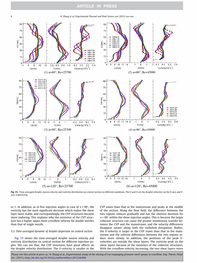
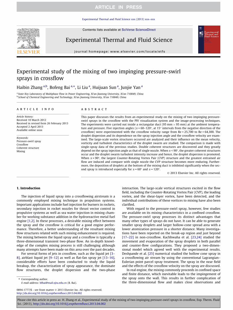
Fig. 15. Time-averaged droplet swarm velocity and vorticity distribution on central section on different conditions. The U and V are the droplet velocities on the X-axis and Y-axis respectively.
6 H. Zhang et al. / Experimental Thermal and Fluid Science xxx (2013) xxx–xxx
to 1. In addition, as in five injection angles in case of a = 90�, thevorticity has the most significant decrease which makes the shearlayer more stable, and correspondingly, the CVP structures becomemore enduring. This explains why the existence of the CVP struc-ture has a higher upper-limit crossflow velocity for double nozzlesthan that of single nozzle.
3.3. Time-averaged dynamic of droplet dispersion on central section
Fig. 15 shows the time-averaged droplet swarm velocity andvorticity distribution on central section for different injection an-gles. We can see that, the CVP structures have great effects onthe droplet velocity distribution. The U-velocity is smaller in the
Please cite this article in press as: H. Zhang et al., Experimental study of the mixSci. (2013), http://dx.doi.org/10.1016/j.expthermflusci.2013.04.002
CVP zones than that in the mainstream and peaks at the middleof the section. Along the flow field, the difference between thetwo regions reduces gradually and has the shortest duration fora = 60� within the three injection angles. This is because the largercoherent structure can cause the greater momentum transfer be-tween the CVP and the mainstream, and the velocity differencesdisappear sooner along with the turbulent dissipation. Rather,the V-velocity is larger in the CVP zones than that in the main-stream and the velocity differences between the two regions re-duce more slowly. In addition, the positions of the peak V-velocities are outside the shear layers. The vorticity peak on theshear layers because of the existence of the coherent structures.With the crossflow velocity increasing, the two shear layers move
ing of two impinging pressure-swirl sprays in crossflow, Exp. Therm. Fluid
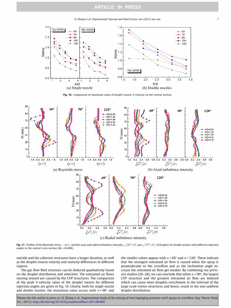
Fig. 16. Comparison of maximum value of droplet swarm V-velocity on the central section.
(a) Reynolds stress (b) Axial turbulence intensity
(c) Radial turbulence intensity
Fig. 17. Profiles of the Reynolds stress, �hu0v0i, and the axial and radial turbulence intensity,ffiffiffiffiffiffiffiffiffiffihu02i
p=hUi and
ffiffiffiffiffiffiffiffiffiffihv 02i
p=hVi, of droplets for double nozzles with different injection
angles in the central cross-section (Re = 45,000).
H. Zhang et al. / Experimental Thermal and Fluid Science xxx (2013) xxx–xxx 7
outside and the coherent structures have a longer duration, as wellas the droplet swarm velocity and vorticity differences in differentregions.
The gas flow filed structure can be deduced qualitatively basedon the droplet distribution and velocities. The entrained air flowsmoving inward are caused by the CVP structures. The comparisonof the peak V-velocity value of the droplet swarm for differentinjection angles are given in Fig. 16. Clearly, both for single nozzleand double nozzles, the maximum value occurs with a = 90� and
Please cite this article in press as: H. Zhang et al., Experimental study of the mixSci. (2013), http://dx.doi.org/10.1016/j.expthermflusci.2013.04.002
the smaller values appear with a = 60� and a = 120�. These indicatethat the strongest entrained air flow is caused when the spray isperpendicular to the crossflow and as the inclination angle in-crease the entrained air flow get weaker. By combining our previ-ous studies [26–28], we can conclude that when a = 90�, the largestCVP structure and the greatest entrained air flow are inducedwhich can cause more droplets enrichment in the external of thelarge-scale vortex structures and hence, result in the non-uniformdroplet distribution.
ing of two impinging pressure-swirl sprays in crossflow, Exp. Therm. Fluid

8 H. Zhang et al. / Experimental Thermal and Fluid Science xxx (2013) xxx–xxx
3.4. Turbulent characteristics of the spray droplets
The turbulent characteristics of the spray droplets are calcu-lated. Fig. 17 shows the Reynolds stress, � hu0v0i (the minus ‘‘�’’indicates the X-axis negative direction), and the axial and radialturbulence intensity,
ffiffiffiffiffiffiffiffiffiffihu02i
p= Uh i and
ffiffiffiffiffiffiffiffiffiffiv 02h i
p= Vh i, of droplets for
the double nozzles. We find that the coherent structures play animportant role in influencing the droplet turbulent behavior. Inthe mixing initial stage all of the three peaks locally on the upperand lower shear layers and decrease to the minimum near the cen-terline of the flow field. Along the flow field, the peak values de-crease and their positions moves inwards as the mainstreamregion converges. For three injection angles, the Reynolds stressand the axial and radial turbulence intensity on the shear layerare greater with a = 60�. This also indicates that when the sprayis against the crossflow, the turbulent intensity increase and themomentum transfer between the gas flow and the droplets are en-hanced and hence, the droplet dispersion is promoted.
4. Conclusion
The present investigation of double pressure-swirl sprays in acrossflow has been helpful in obtaining a deeper insight into thedynamics involved in the complex mixing problem. The main con-clusions of the mixing dynamic features of double-spray in cross-flow are as follows:
(1) Two obvious CVP structures and the coherent structuresdominated the droplet dispersion. Like the single nozzle,the coherent structure greatly depends on the spray injec-tion angle. When a < 90�, the interactions among the doublesprays and the crossflow are enhanced which result in thegreater coherent structures and the increased droplet swarmturbulent intensity near the shear layers.
(2) Compare with single nozzle, the enrichment of droplets atthe bottom of the mixing duct is inhibited significantly whenthe second spray is introduced especially for a = 60� anda = 120�.
(3) When a = 90�, the largest CVP structure and the greatestentrained air flow are induced, and compare with single noz-zle the CVP structure becomes more enduring.
Acknowledgment
The financial supports from the National Nature Science Foun-dation of China for Creative Research Groups under the contractNo. 51121092 are highly appreciated.
References
[1] W.P. Tian, T.M. Cai, H.J. Lu, P. Gao, Thermodynamic calculation for waterramjet, Journal of Solid Rocket Technology 29 (2) (2006) 95–98.
[2] Y.J. Yang, M.G. He, H.D. Xu, Thermodynamic cycle performance for waterramjet motors, Journal of Propulsion Technology 30 (4) (2009) 474–478.
Please cite this article in press as: H. Zhang et al., Experimental study of the mixSci. (2013), http://dx.doi.org/10.1016/j.expthermflusci.2013.04.002
[3] P.K. Wu, K.A. Kirkendall, R.P. Fuller, A.S. Nejad, Breakup processes of liquid jetsin subsonic crossflows, AIAA Paper (1996) 96–3024.
[4] T. Inamura, N. Nagai, Spray characteristics of liquid jet traversing subsonicairstreams, Journal of Propulsion and Power 13 (1997) (1997) 250–256.
[5] S.B. Tambe, S.M. Jeng, H. Mongia, Liquid jets in subsonic crossflow, AIAA Paper(2005) 2005–2731.
[6] K.A. Sallam, C.L. Ng, R. Sankarakrishnan, C. Aalburg, K. Lee, Breakup ofturbulent and non-turbulent liquid jets in gaseous crossflows, AIAA Paper(2006) 1517–2006.
[7] M. Costa, M.J. Melo, J.M.M. Sousa, Y. Levy, Spray characteristics of an angledliquid injection into subsonic crossflows, Journal of AIAA 44 (2006) 646–653.
[8] K. Bunce, J.G. Lee, D.A. Santavicca, Characterization of liquid jets-in-crossflowunder high temperature, high velocity non-oscillating and oscillating flowconditions, AIAA Paper (2006) 1225–2006.
[9] A. Lozano, F. Barreras, G. Hauke, C. Dopazo, Longitudinal instabilities in an air-blasted liquid sheet, Journal of Fluid Mechanics 437 (2001) 143–173.
[10] L.K.B. Li, S.I. Green, M.H. Davy, D.T. Eadie, Viscoelastic air-blast sprays in across-flow. Part 1: Penetration and dispersion, Atomization and Sprays 20 (8)(2010) 697–720.
[11] L.K.B. Li, S.I. Green, M.H. Davy, D.T. Eadie, Viscoelastic air-blast sprays in across-flow. Part 2: Droplet velocitys, Atomization and Sprays 20 (8) (2010)721–735.
[12] M.Y. Leong, V.G. McDonell, G.S. Samuelsen, Mixing of an Airblast-AtomizedFuel Spray Injected into a Crossflow of Air, NASA/CR (2000) 210467.
[13] G.E. Lorenzetto, A.H. Lefebvre, Measurements of drop size on a plain-jetairblast atomizer, Journal of AIAA 15 (7) (1977) 1006–1010.
[14] R. Harari, E. Sher, Bimodal drop size distribution behavior in plain-jet airblastatomizer sprays, Atomization and Sprays 8 (3) (1998) 349–362.
[15] P.C.H. Miller, M.C. Butler Ellis, C.R. Tuck, Entrained air and droplet velocitiesproduced by agricultural flat-fan nozzles, Atomization and Sprays 6 (1996)693–707.
[16] J.C. Phillips, P.C.H. Miller, N.H. Thomas, Air flow and droplet motions producedby the interaction of flat-fan spray and cross flows, Atomization and Sprays 10(2000) 83–103.
[17] D.P. Schmidt, I. Nouar, P.K. Senecal, C.J. Rutland, J.K. Martin, R.D. Reitz,Pressure-Swirl Atomization in the Near Field, SAE Technical 1999-01-0496.
[18] J.T. Yang, A.C. Chen, S.H. Yang, K.J. Huang, Flow analysis of spray patterns ofpressure-swirl micro atomizers, in: Proceedings of PSFVIP-4. June 3–5 (2003)F4052.
[19] C.A. Chryssakis, D.N. Assanis, J.K. Lee, K. Nishida, Fuel Spray Simulation ofHigh-Pressure Swirl-Injector for DISI Engines and Comparison with LaserDiagnostic Measurements, SAE 2003-01-0007.
[20] J.Q. Xue, Computational Simulation of Flow inside Pressure-Swirl Atomizers,Division of Research and Advanced Studies of the University of Cincinnati,November 8, 2004.
[21] T. Marchione, C. Allouis, A. Amoresano, F. Beretta, Experimental investigationof a pressure swirl atomizer spray, Journal of Propulsion and Power 23 (5)(2007) 1096–1101.
[22] S. Lee, W. Kim, W. Yoon, Spray formation by a swirl spray jet in low speedcross-flow, Journal of Mechanical Science and Technology 24 (2) (2010) 559–568.
[23] S.S. Kachhwaha, P.L. Dhar, S.R. Kale, Experimental studies and numericalsimulation of evaporative cooling of air with a water spray – I. Horizontalparallel flow, International Journal of Heat Mass Transfer 41 (1998) 447–464.
[24] S.S. Kachhwaha, P.L. Dhar, S.R. Kale, Experimental studies and numericalsimulation of evaporative cooling of air with a water spray – II. Horizontalcounter flow, International Journal of Heat Mass Transfer 41 (1998) 465–474.
[25] S. Deshpande, J. Gao, M.F. Trujillo, Characteristics of hollow cone sprays incrossflow, Atomization and Sprays 21 (4) (2011) 349–361.
[26] B.F. Bai, H.B. Zhang, L. Liu, H.J. Sun, Experimental study on turbulent mixing ofspray droplets in crossflow, Experimental Thermal and Fluid Science 33 (2009)1012–1020.
[27] L. Liu, Mixing of Spray in Crossflow, Xi’an Jiaotong University, Xi’an, 2010.[28] H.B. Zhang, B.F. Bai, L. Liu, H.J. Sun, J.J. Yan, Droplet dispersion characteristics of
the hollow cone sprays in crossflow, Experimental thermal and fluid science45 (1) (2013) 25–33.
[29] H.B. Zhang, B.F. Bai, L. Liu, H.J. Sun, J.J. Yan, Mixing of hollow-cone spray witha confined crossflow in rectangular duct, Journal of AIAA 53 (3) (2013) 615–622.
ing of two impinging pressure-swirl sprays in crossflow, Exp. Therm. Fluid