experimental studies on pressurized escape routesmail.seedengr.com/experimental studies on... ·...
TRANSCRIPT

Ser TH1 N21r 2 no. 631 c . 2
BLDG NATIONAL RESEARCH COUNCIL OF CANADA
CONSEIL NATIONAL DE RECHERCHES DU CANADA
Experimental Studies on Pressurized Escape Routes
by George T. Tamura
Reprinted from
ASHRAE Transactions
Vol. 80, Part 2,1974 p. 224 - 237
dy permission of the American Society of Heating,
Refrigerating and Air-Conditioning Engineers, Inc.
Research Paper No. 631
of the Division of Building Research
Price 25 cents OTTAWA

L'auteur prbsente les resultats d'essais effectubs sur deux edifices en vue d'6valuer I'efficacitb de la pressurisation pour empgcher I'effondrement des puits d'escalier en cas d'incedie. On vbrifie I'effet de garder quelques portes ouvertes et I'effet d'une injection d'air A la base ou au sommet du puits. L'auteur recommande I'injection d'air A plusieurs niveaux afin d'assurer une pressurisation uniforme du puits d'escalier et un 6coulement d'air dans I'ensemble du puits. On presente egalement les donnbes des essais concernant 11btanch6itb A I'air des murs et des portes des p~lits d'escalier ainsi que la resistance A I'bcoulement A I'intbrieur du puits.
ETUDES EXPERIMENTALES DES ISSUES SOUS PRESSION

No. 2319
.GEORGE T. TAMURA Member ASHRAE
The pressurization of s ta i r shafts as a means of providing smoke-free escape routes during a f i r e has received much attention in recent years by a number of investigators and code authorities (1-11). This method has special application to high-rise buildings as evacuation time can be long and f i re fighting difficult; hence safe vertical passageways must be assured for the duration of a f i re . It entails injecting outside air into the s ta i r shaft to establish flow f rom i t to adjacent spaces , thus preventing entry of smoke into the s t a i r shaft as well a s dis- per sing any smoke within it.
The design of a s ta i r pressurization system requires information on the airtightness of walls and doors of s ta i r shafts and on the resis tance to a i r flow through the s ta i r shaft itself. The tes ts described in this paper were conducted to obtain this information for two high-rise buildings. It must be anticipated that several s t a i r doors will be open during a f i re to permit evacuation and f i re fighting. This reduces the pressures in the s ta i r shaft and can adversely affect the performance of the smoke control system. The effect of having some s ta i r doors open was also checked, therefore, a s well a s the differences that occur when air is injected at the top or,bottom of the shaft.
DESCRIPTION OF BUILDINGS AND TEST PROCEDURE
The s ta i r shaft of building A serves 23 s tor ies (including one basement floor) and has a con- ventional stairway. The walls of the s ta i r shafts in building A a r e constructed of cast-in- place concrete. Building B differs in that its s ta i r shaft se rves 37 s tor ies ( 5 of which a r e underground), the s ta i r s a r e the scissor-type (two s ta i r s in a single shaft), and the walls of the shaft a r e of concrete blocks. The doors between the s t a i r shaft and the floor spaces are the same in the two buildings. The dimensions of the s ta i r shafts and the buildings a r e given in Table I.
TABLE I
Description of Stair Shafts. Buildings A and B
Building A Building B
Building plan 126 ft by 146 ft 107 ft by 146 f t No. of s ta i r shafts 2 2 Floors served above grade 2 2 3 2 Floors served below grade 1 5 Typical floor height 10 f t , 7 in. 11 f t , 6 in. Over -all height 258 ft 425 f t Shaft size 6.75 by 14.25 ft 8. 5 f t by 31.0 ft Typical door size 36 in. by 84 in. 36 in. by 84 in. Construction conventional, sc i ssors , concrete
cast-in-place blocks, concrete, plaster paint finish finish
G . T . T a m u r a , N a t i o n a l R e s e a r c h C o u n c i l o f C a n a d a , D i v i s i o n o f B u i l d i n g R e s e a r c h , O t t a w a , C a n a d a
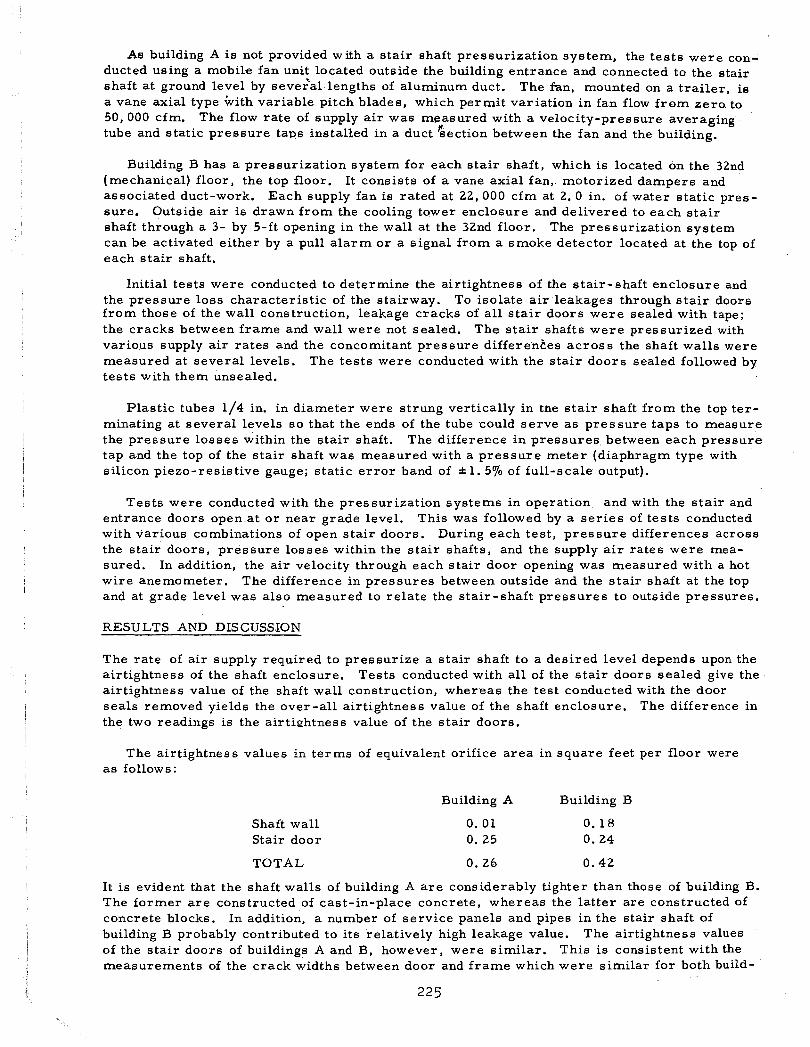
As building A is not provided with a s ta i r shaft pressurization system, the tes ts were con- ducted using a mobilte fan unit located outside the building entrance and connected to the stair shaft a t ground level by seveGal lengths of aluminum duct. The fan, mounted on a t ra i le r , i s a vane axial type b i th variable pitch blades, which permit variation in fan flow f rom zero to 50,000 cfm. The flow rate of supply a i r was measured with a velocity-pressure averaging tube and static pressure taps installed in a duct Gection between the fan and the building.
Building B has a pressurization system for each s ta i r shaft, which is located on the 32nd (mechanical) floor, the top floor. It consists of a vane axial fan, motorized dampers and associated duct-work. Each supply fan is rated at 22, 000 cfm at 2. 0 in. of water static pres- sure. Outside air is drawn f rom the cooling tower enclosure and delivered to each s t a i r shaft through a 3- by 5-ft opening in the wall at the 32nd floor. The pressurization system can be activated either by a pull a l a rm or a signal from a smoke detector located at the top of each s ta i r shaft.
Initial tests were conducted to determine the airtightness of the stair-shaft enclosure and the pressure loss characteristic of the stairway. To isolate a i r leakages through s t a i r doors f rom those of the wall construction, leakage cracks of a l l s ta i r doors were sealed with tape; the cracks between frame and wall were not sealed. The s ta i r shafts were pressurized with various supply a i r rates and the concomitant pressure differences ac ros s the shaft walls were measured at several levels. The tes ts were conducted with the s ta i r doors sealed followed by tes ts with them unsealed.
Plastic tubes 1/4 in. in diameter were strung vertically in the s ta i r shaft from the top ter- minating at several levels so that the ends of the tube could se rve as pressure taps to measure the pressure losses within the s ta i r shaft. The difference in pressures between each pressure tap and the top of the stair shaft was measured with a pressure meter (diaphragm type with silicon piezo-resistive gauge; static e r r o r band of * 1. 5% of full-scale output).
Tests were conducted with the pressurization systems in operation and with the s ta i r and entrance doors open a t o r near grade level. This was followed by a s e r i e s of tests conducted with various combinations of open s ta i r doors. During each test , p ressure differences across the stair doors, p ressure losses within the s ta i r shafts, and the supply a i r rates were mea- sured. In addition, the a i r velocity through each s ta i r door opening was measured with a hot wire anemometer. The difference in pressures between outside and the s ta i r shaft at the top and at grade level was also measured to re la te the stair-shaft pressures to outside pressures .
RESULTS AND DISCUSSION
The rate of a i r supply required to pressurize a s ta i r shaft to a desired level depends upon the airtightness of the shaft enclosure. Tests conducted with all of the s ta i r doors sealed give the airtightness value of the shaft wall construction, whereas the test conducted with the door seals removed yields the over-all airtightness value of the shaft enclosure. The difference in the two readings is the airtightness value of the s ta i r doors.
The airtightness values in te rms of equivalent orifice a rea in square feet per floor were as follows:
Building A Building B
Shaft wall Stair door
TOTAL 0. 26 0.42
It is evident that the shaft walls of building A a r e considerably tighter than those of building B. The former a r e constructed of cast-in-place concrete, whereas the latter are constructed of concrete blocks. In addition, a number of service panels and pipes in the stair shaft of building B probably contributed to its relatively high leakage value. The airtightness values of the s ta i r doors of buildings A and B, however, were similar. This i s consistent with the measurements of the crack widths between door and f rame which were similar for both build-

ings with average values of 3/8 in. at the bottom and 3/32 in. for the remaining three aides.
The resistance to flow caused by the path iormed by the shaft wall and s ta i rcase can affect, the uniformity of vertical pressurization in the s ta i r shaft. The pressure gradient inside the s ta i r shaft i s also affected by the change in flow ra te by leakage flow through the shaft wal l and the column weight of a i r , assuming that there i s no temperature gradient and that the cross-sectional a r ea of the s ta i r shaft is constant for the height of the shaft (1,2). To mini- mize the effect of the leakage flow, pressure losses of the ,stair shaft of building A were measured with all s ta i r doors sealed making the shaft wall virtually airtight. The pressure losses measured a r e thus due to the flow resistance of the s ta i r shaft, as the effect of column weight of air is also eliminated with the use of vertical runs of plastic tubes as previously described. The s ta i r shaft was pressurized with supply a i r ra tes of 9,000 and 18, 000 cfm at grade level with the s ta i r door a t the top level open. The flow rates measured at the entrance and exit of the s ta i r shaft indicated leakage flow through the shaft walls of l e s s than 570 of the supply a i r rates.
The measurement of the pressure loss characteristics of the scissor s t a i r s of building B was not attempted as i ts shaft walls were found to be quite leaky and hence a realistic value could not be expected. Tests were conducted, however, on.the scissor s ta i r s of ar, l l - s to rey building (building C) whose shafts a r e constructed of cast-in-place concrete. Measurements '
of the airtightness of these shaft walls gave leakage values s imilar to those of building A. With the s ta i r doors sealed, the s ta i r shaft was pressurized with flow ra tes of 15,000, 20,000 and 25,000 cfm.
The pressure loss characteristics of the s ta i r shafts for both buildings A and C were linear with height; the pressure losses varied with the square of the supply a i r rates. Fig. 1 gives the relationship between the supply a i r ra tes and the average pressure losses per floor, f rom which the pressure loss factors were calculated. The pressure loss factor a s defined in this pape'r i s given by the following equation:
where K = pressure loss factor, per floor
A P = pressure loss, in. of water
N = number of floors
VH = velocity head, in. of water
The value of VH i s based on the a i r flow ra te divided by the f u l l c ross -sectional a r ea of the conventional s ta i r shaft, and one- half the cross-sectional a r ea of the scissor s ta i r which con- tains two separate stairways.
The calculation of p ressure loss factors yielded values of 45 and 28 for the conventional stair shaft (building A) and the scissor s ta i r shaft (building C) respectively.
The scissor s ta i r shaft differs f rom that of the conventional s ta i r in that the stairway con- tinues in the same direction between floors, whereas, in the conventional s ta i r shaft the stairway makes a 180-deg turn mid-way between floors. The number of 180-deg turns in the conventional stair shaft, therefore, would be twice a s great as that for the scissor s ta i r serving the same number of floors. The conventional stair shaft usually has no party wall at the inner railings, whereas the s ta i rcase of the scissor s ta i r i s enclosed by a wall on both sides of the tread. The size of the flow channel for the sc i ssor stair i s , therefore, much less than for the conventional s ta i r shaft. The values of pressure loss factors can facilitate the calculations of p ressure losses in a pressurized s ta i r shaft. Such calculations are necessary in the design of a s ta i r pressurization system a s high pressure losses within a s ta i r shaft can

result in excessive p ressure differentials ac ross the s ta i r doors, which will interfere with their operation.
Additional test data a r e required to determine the effect of such paramete rs a s the s ize of well between inner rail ings, direction of ver t ical flow, and s ta i rcase configuration.
Air Injection Into the Stair Shaft a t the Bottom (Building A)
For a l l of the tes ts the single s t a i r shaft of building A was pressur ized with outside a i r sup- plied f rom the mobile fan unit ducted to the s ta i r door opening on the ground floor. The supply a i r r a te of 20, 000 cfm was based on the intended uniform pressurization of 0. 10 in. of water assuming no pressure losses with a l l but one s t a i r door closed. The outside tem- perature during the tes ts was about 50 F.
Tes t No. A1 was conducted with the s ta i r and freight entrance doors on the basement .level open followed by tes t No. A2 with only the s ta i r door on the 22nd (mechanical) floor open. During both tes ts the building a i r -handling systems were in nor ma1 operation. The resultant p r e s su re difference readings ac ro s s the s t a i r doors for both tes ts , given in Fig. 2, show that the p ressure difference patterns for the two tes t s differ significantly. Fo r test No. A1 the p ressure differences ac ross the s ta i r doors f r o m the f i r s t floor to the 21st floor varied f rom 0.10 to 0. 20 in. of water , whereas for test No. A2 they var ied f rom 1. 3 to -0.3 in. of water. The total p ressure drops inside the s ta i r shaft f r om the f i r s t to the 22nd floor were 0. 07 and 1.68 in. of water for test Nos. A1 and A2, respectively.
The nonuniformity of pressurization can be attributed to the p ressure LOSS character is t ic of the s ta i r shaft. This can be significant for high flow r a t e s a s in t es t No. A2 with p ressure differences ac ross the s ta i r doors on the lower floors that a r e much grea te r than the maximum permissible p ressure difference with regard to e a se of door operation of 0.40 in. of water (3). With a flow ra te of 13, 100 cfm through the s t a i r door opening on the basement f loor, the up- ward flow ra te for t es t No. A1 was'about one third of that for test No. A2 and hence the pre- surization was much more uniform. Cresci (2) and Koplon (4) reported similar resu l t s from tes ts conducted on pressur ized s t a i r shafts.
The pressure difference of 0. 56 in. of water ac ross the s ta i r door of the 22nd (mechanical) floor for test No. A1 (point a of Fig. 2) indicates that the p ressures on this floor a r e lower than those of the typical floors by 0.46 in. of water. This was probably caused by p r e s - surization on the typical floors (0. 18 in. of water) and suction on the mechanical floor (0.25 in. of water) with the operation of the building air-handling systems. This would explain the negative p ressure differences ac ross the s t a i r doors above the 16th floor for test No. A2 as the stair-shaft p ressures would tend to decrease and approach those of the mechanical floor with the s t a i r door open on that floor. These t es t s indicate that a large opening a t the top of the s ta i r shaft o r substantial mechanical exhaust a t the top with air injection at the bottom can lead to excessive stair-shaft pressurization a t lower levels and to inadequate pressurization at upper levels.
Test No. A3 was conducted with the building air-handling systems shut down and with the s ta i r and freight entrance doors on the basement floor open. All other s t a i r doors we re closed. With the s t a i r shaft pressur ized the flow rate through the open s t a i r door on the base- ment floor was 14, 200 cfm giving an upward flow rate of 5, 800 cfm in the stair shi f t . The p r e s su re characterist ics of the two s ta i r shafts, floor space and outside caused by building stack action and stair-shaft pressurization a r e shown in Fig. 3. The horizontal distances between the s ta i r shaft and the floor space p r e s su re characterist ics represent the p ressure differences ac ross the s ta i r doors. Similarly, the horizontal distances between the floor space and outside p ressure character is t ics represent the p ressure differences a c ro s s the exterior walls.
The neutral plane of the building is located a t about the 13th floor, below which the pres- su r e s of the floor spaces a r e higher than those of s ta i r shaft No. 2 (not pressurized) and above which the reverse occurs. The pressures of s ta i r shaft No. 1 (pressur ized) a r e , a s expected,

higher than those of the floor space and outside for the ent i re height of the shaft. The p res - s u r e differences a c r o s s the s t a i r doors on the typical f loors var ied f r o m 0. 150 to 0.200 in. of wa te r , which a r e g rea te r than those obtained with the building air-handling systems in normal operation ( t es t No. Al j ; the p r e s s u r e differeace a c r o s s the s t a i r door of the 22nd (mechanical) f loor, however, was much lower. It would appear that the higher leakage ra te of the shaft wall a t this floor with the air-handling systems operating probably resul ted in p r e s s u r e differences a c r o s s the s t a i r doors of the, typical f loors which w e r e lower than those with air-handling sys tems shut down. .
With injection of untempered outside a i r during cold weather , the s t a i r -shait temperatures can be much lower than those of the surroundings. To investigate this, a i r temperatures of s t a i r shaft No. 1 were measured a t severa l levels one-half hour after the s t a r t of t e s t No. k 3 ; the ver t ica l temperature gradient i s shown in Fig. 4. The r a t e of inc rease in a i r temperature is the greates t a t the point of a i r injection; i t dec reases with distance away f rom this point a s the a i r temperature approaches the inside ambient temperature.
Tes t s Nos. A4 and A5 were conducted to investigate the performance of the s t a i r p r e s - surization sys tems with other s t a i r doors open in addition to the one on the basement floor. All building air-handling sys tems were shut down a s in t e s t No. A3. It was assumed that during a f i r e the exit s t a i r door a t o r near grade level and the s t a i r door on the f i r e f loor could be expected to be open for an extended period. With this in mind, t e s t No. A4 w a s con- ducted f i rs t ly with the s t a i r door a t the 4th floor open and secondly with the stair door a t the 16th floor open, the two floors represent ing a f i r e a t low and high levels.
The p r e s s u r e differences a c r o s s the s t a i r doors for both t e s t conditions a r e shown in Fig. 5 together with those of t e s t No. A3, during which a l l s t a i r doors above g rade were closed. There was a substantial dec rease in p r e s s u r e difference when the s t a i r doors were opened. The average a i r velocities through the open s t a i r doors w e r e 265 fpm (5300 cfm) and 180 fpm (2600 cfm) for the 4th and 16th floor respectively. A minimum acceptable a i r velocity of 200 fpm i s suggested in Ref 5 to prevent smoke f r o m entering the s t a i r shaft.
Tes t No. A5 was conducted with the s t a i r doors on floors 4 , 7, 8, 10, 11, 13, 14, 16, 17, 19 and 20 open to simulate evacuation. The p r e s s u r e differences a c r o s s the s ta i r doors up to the 4th floor were s imilar to those with only the s t a i r door on the 4th floor open. Above the 4th floor, however, p r e s s u r e differences were considerably less: values varied f r o m 0 to 0.015 in. of water (Fig. 5). The average flow velocities through the door opening w e r e 275, 70, 50 and 12 fpm for f loors 4, 10, 16 and 20 respectively. These values suggest that the effectiveness of the s ta i r -shaf t pressur izat ion sys tem with a i r injection a t the bottom is not affected when severa l s t a i r doors a r e opened above the f i r e floor but i s adversely affected when severa l s t a i r doors a r e opened below the f i r e floor. A separate t e s t with s t a i r doors of f loors 3, 4 and 5 open resulted in an average flow velocity of 120 fpm through the s t a i r door opening of the 4th floor. In assess ing these resu l t s in the context of evacuation i t should be borne in mind that the period during which each s ta i r door other than the ones on the exi t and f i re flooxs i s open i s only a few minutes (the t ime taken by the occupants to vacate the floor).
Air Injection a t Top of Stair Shaft, Building B
The sc i s sor s t a i r s of building B were p ressur ized with the two separate pressur izat ion sys tems located a t the 32nd (mechanical) floor. Although the s ize of both fans is the same, a t the t ime of tes t the flow capacit ies were different a s the one fan had more blades than the other. The outside temperature was 30 F during the tes ts .
T e s t No. B1 was conducted with the building a i r handling systems shut down and with all s t a i r doors closed. Supply a i r r a t e s were 16, 500 cfm and 14, 200 c fm for s ta i r shafts NOS. 1 and 2, respectively. P r e s s u r e differences a c r o s s the s t a i r doors of s t a i r shaft No. 1 are shown in Fig. 6, which shows that the p r e s s u r e differences a c r o s s the s t a i r doors a r e much grea te r a t upper levels than those a t lower levels. This is associated with the p r e s s u r e losses in the s t a i r shaft also shown in Fig. 6 caused by the flow res is tance of the s ta i rway

resulting in shaft p r e s su re s that a r e substantially greater a t upper levels than those a t lower levels. P r e s s u r e differences ac ross s t a i r doors we re l e s s than 0.40 in. of water except for the top two typical f loors and the mechanical f loors. The p r e s su re losses , and hence the variation in the p r e s su re differences ac ross the s t a i r doors, would have been greater if the s t a i r shaft had been the conventional type.
F r o m Fig. 7 , which shows the p ressure character is t ics of the floor space , s t a i r shaf ts Nos. 1 and 2 and outside, i t can be s een that the p ressures of s ta i r shaft No. 1 a r e higher than those of s t a i r shaft No. 2 due to the higher supply a i r r a t e for the fo rmer . The neutral plane of the building with the s ta i r -shaf t pressur izat ion sys tems off was a t the 26th floor level. With the stair-shaft pressurization sy s t em on, the floor space p ressures a lso in- creased which resulted in the lowering of the neutral plane to the 16th floor level (Fig. 7). The extent of indirect pressur izat ion of the floor spaces would depend upon the airt ightness of the exterior walls and those of the walls of the s ta i r shaft a s they comprise the res is tance to flow in s e r i e s f r om the s t a i r shaft to the exterior. The resultant p r e s su re differences ac ross the s t a i r doors would depend, therefore, on the airt ightness of the exterior walls as well a s that of the walls of the s ta i r shaft.
Air temperatures of s ta i r shaft No. 1 we re measured one-half hour af ter the s t a r t of test No. B1. These a r e shown in Fig. 8 which shows a s imilar character is t ic to those obtained for building A (Fig . 4). During cold weather, the pressur izat ion of the s t a i r shaft with un- tempered outside a i r can resu l t in uncomfortable conditions in the s t a i r shaft on s eve ra l floors extending f rom the region of a i r injection.
Test No. B2 was s imilar to t es t No. B1 except that the s t a i r and entrance doors on the f i r s t floor were open. As shown in Fig. 6 the p r e s su re differences a c ro s s the s ta i r doors were lower for this situation than they were for t es t No. B1. The average a i r velocities through the open s t a i r doors were 130 and 125 fpm for s t a i r shafts Nos. 1 and 2 respectively.
Tes t No. B3 was also conducted d i t h the s t a i r and entrance doors on the f i r s t f loor open. In addition, the s t a i r door on the 28th floor for s ta i r shaft No. 1 and s t a i r doors on the 24th to 28th floors inclusive for s ta i r shaft No. 2 were also open. The supply a i r ra tes increased f rom 16, 500 cfm to 19,000 cfm for s ta i r shaft No. 1 and f rom 14,200 cfm to 16, 200 c fm for s t a i r shaft No. 2. Opening of s ta i r doors a t upper levels apparently reduced the sy s t em res is tance which resulted in an increase in the fan delivery. Stack action during cold weather can also affect the fan delivery. The flow r a t e i s decreased by a fan located at the top and increased by a fan located a t the b ~ t t o m of a building.
P r e s s u r e differences a c ro s s the s ta i r doors given in Fig. 9 a r e , below the 28th floor, l e s s than 0.08 in. of water for both s ta i r shafts. As the a i r velocities ac ross the s t a i r door openings on the f i r s t floor were low and could not be accurately measured, the flow patterns we re checked with smoke t races . In both s ta i r shafts a i r flowed into the shaft through the lower par t of the ~ p e n i n g and out above it. In addition, the s t a i r doors of the 3rd floor for both s ta i r shafts we re also opened. The direction of flow for these openings was f r o m the s t a i r shaft% to the floor spaces for the entire opening for s t a i r shaft No. 1 and up to 6 in. f r om the top of the s t a i r door fo r s ta i r shaft No. 2, above which the flow direction was in- dete rminante.
The p r e s su re character is t ics for t es t No. B3 a r e shown in Fig. 10. Comparison of this Figure with Fig. 7 for tes t No. B1 shows that with several doors opened the p ressures of the s ta i r shafts a r e decreased and those of the floor spaces a r e increased with the neutral plane lowered f rom the 16th to the 4th floor level. This was caused by an increase in the p r e s - surization flow and a decrease in the res is tances to flow of the s ta i r -shaf t walls relative to those of the exter ior walls.
CONCLUSIONS
1. The supply a i r r a te based on uniform pressur izat ion of 0. 10 in. of water with one stair door open and a l l o thers closed provides sufficient pressur izat ion to maintain the stair

shaft tenable when the s ta i r doors on the f i re floor and ground floor a r e open. These
doors can be expected to be open fo r an extended period during a f i re .
2. A substantial decrease in s ta i r -shaf t pressurization and a possibility, therefore, of staid- shaft contamination can be expected if severa l additional doors a r e open. These doors a r e likely to be open, however, for a much shor ter duration; the t ime for each door i n the open position is that required by the occupants to vacate a floor.
3. The secondary objective of s ta i r -shaft pressur izat ion i s to p.rovide adequate flow for dilution throughout the s ta i r shaft a s there i s a possibility of i t s being contaminated by smoke. Air injection a t the bottom of the s ta i r shaft r esu l t s in a substantial loss of supply a i r through the open exit door. When a i r is injected a t the top, the resultant p r e s su re differences ac ross the s ta i r doors cause a high ra te of leakage flow a t upper levels in addition to creating problems with operation of the s ta i r doors on these floors.
4. The best approach would appear to be to inject a i r a t s eve r a l levels ra ther than only a t the top or bottom. In this way a substantial flow of a i r for dilution throughout the s t a i r shaft and a more uniform pressurization can be achieved. The number of outlets and locations for a i r injection should be such that p ressure differences a c ro s s the s t a i r doors a r e between 0.10 to 0.40 in. of water with a l l s ta i r doors closed except for the one on the ground floor. Relief dampers should be considered if no provision i s made for en- suring continuous opening of the s t a i r door at the ground floor level during a f i re . F o r very tal l buildings, i t may also be necessary to t reat the s t a i r shaft a s a number of s eg - ments, i. e. , provide a separate pressur izat ion system for each compartment.
5. The a i r leakage ra tes of the s t a i r doors of both tes t buildings were s imilar . Those of the shaft walls of cast-in-place concrete were negligible whereas those of the shaft walls of concrete blocks were substantial. The p r e s su re loss factors were 45 and 28 for the con- ventional and sc i s sor s ta i r shafts respectively. Such data, which a t present a r e spa r s e , a r e required in the design of a stair-shaft pressur izat ion system.
ACKNOWLEDGEMENTS
The author gratefully acknowledges the contribution of the T r i ze c Equities Limited and the Department of Public Works fo r permiss ion and assistance i n carrying out t es t s in their buildings.
The author also acknowledges the contributions by J. H. McGuire and C. Y. Shaw for the discussion and planning of the field t es t s and R. G. Evans fo r his assistance in carrying out the field tes ts .
This paper i s a contribution f r o m the Division of Building Research, National Research Council of Canada, and i s published with the approval of the Director of the Division.
REFERENCES
1. P. R. DeCicco, Smoke and F i r e Control i n High-Rise Office Buildings, P a r t I - Full Scale Tes t s for Establishing Standards, presented a t ASHRAE Symposium on Experience and Applications on Smoke and F i r e Control, Louisville, Kentucky, June 1973.
2. R. J. Cresci , Smoke and F i r e Control in High-Rise Office Buildings, P a r t I1 - Analysis of Stair Pressur iza t ion Systems, presented a t ASHRAE Symposium on Experience and Applications on Smoke and F i r e Control, Louisville, Kentucky, June 1973.
3. R. E. Bar re t t and D. W. Locklin, Computer Analysis of Stack Effect i n High-Rise Build- ings, ASHRAE Transactions, Vol. 74, P a r t 11, 1968.
4. N. A. Koplon, A Par t i a l Report of the Henry Grady F i r e Tes t s (Atlanta, Georgia) p resen- ted a t ASHRAE Symposium on Experience and Applications on Smoke and F i re Control, Louisville, Kentucky, June 1973.
2 30

5. P. J. Hobson and L. J. Stewart, Pressur izat ion of Escape Routes in Buildings, Heating and Ventilating Research Association, Bracknell, Berkshire , January 1973.
6. G. T. Tamura, J. H. McGuire and A. G. Wilson, Air Handling Systems for Control of Smoke Movement, ASHRAE Symposium Bulletin, F i r e Hazards in Buildings, San Francisco, Calif. , January 1970.
7. E. G. Butcher, P. J. Fardel l and J. Clarke, Pressur izat ion as a Means of Controlling the Movement of Smoke and Toxic Gases on Escape Routes, JFRO Symposium No. 4 , Movement of Smoke on Escape Routes in Buildings, Paper 5, Watford, 1969.
8. J. G. Degenkolb, Smoke Proof Enclosures, ASHRAE Symposium Bulletin, Design Con- siderations for F i r e Safety, Philadelphia, Penn. , January 1971.
9. The City of New York, Local Law No. 5, F i r e Safety Requirements and Controls, January 1973.
10. Standards Association of Australia, Committee ~ ~ / 4 1 Ventilation and Air Conditioning, Draft Australian Standard Code for Mechanical Ventilation and Air Conditioning in Buildings. P a r t 2, F i r e Precautions in Buildings with Air Handling Systems, May 1970.
11. Uniform Building Code, Vol. 3, Housing 1970. Smokeproof Enclosures , Chapter 33, Section 3309. International Conference of Building Officials, 50 South Los Robles, Pasadena, Calif.

10,000 20,000 30,000 40,000
F L O W RATE, C F M
LL
: 0.12- b. 3 Y
O 0.10- I U z -
0.08- LL
0
2 LL
LL 0.06- W n
V)
V)
2 0.04- w LL
3 V) n 0.02- W M L
F i g . 1 P r e s s u r e l o s s c h a r a c t e r i s t i c o f s t a i r s h a f t s
I I I 1
- C O N V E N T I O N A L STAIR S H A F T B U I L D I N G A SHAFT S I Z E - 6 . 7 5 x 1 4 . 2 5 ft. - F L O O R H E I G H T - 1 0 . 6 F T
-
-
-
S C I S S O R S T A I R , B U I L D I N G C - SHAFT S I Z E 7 . 8 4 x 34 .5 ft.
F L O O R H E I G H T - 13.0 FT
I I
22M
2 0 LEGEND
18 0 Test no. Al , supply air rate 20,000cfm stair door on basement
16 v, E 0 Test no. A2, supply air rate 0 14 20,000cfm stair door on 22 nd 0 L 1 2
;lo 0 UTSlDE TEMPERATURE,
I 0 8 I B U I L D I N G AIR
6 H A N D L I N G SYSTEMS I N N O R M A L O P E R A T I O N
4
2
B
PRESSURE DIFFERENCE ACROSS STAIR DOOR, I N C H O F WATER
F i g . 2 P r e s s u r e d i f f e r e n c e s a c r o s s s t a i r d o o r s f o r t e s t N O . A I a n d t e s t N o . A2 o f b u i l d i n g A

/ STAIR SHAFT N O . 2
STAIR SHAFT N O . 1 PRESSURIZED
22M
2 0
18
16 V) 0 Stair shaft no. 1
14 NEUTRAL PCA @ Stair shaft no. 2 9 L 12 Floor space
+ 10 AIR INJECTION AT
x FIRST FLOOR, 20,000CFM
8 BASEMENT STAIR DOOR OUTSIDE TEMPERATURE,
W I
6
4 PRESSURE DIFFERENCE SCALE
2 0 . 2 0 0 .40 0 .60
B
ABSOLUTE PRESSURE - F i g . 3 P r e s s u r e c h a r a c t e r i s t i c s w , i t h
s t a i r s h a f t No. 1 p r e s s u r i z e d , t e s t No. A 3 of b u i l d i n g A
2 2
2 0 A I R I N J E C T I O N A T F I R S T F L O O R
1 8 M E A S U R E M E N T 5 T A K E N
1 6 O N E - H A L F H O U R A F T E R V)
w S T A R T O F TEST N O . A 3 0 14 0 2 1 2
; 1 0 I (3 - 8 O U T S I D E T E M P E R A T U R E , 5 0 ° F W
I
6
4
2
B
A I R T E M P E R A T U R E , OF F i g . 4 A i r t e m p e r a t u r e s of s t a i r s h a f t
No.1 of b u i l d i n g A d u r i n g t e s t A 3

I LEGEND -- - -
pa o 0 Test no. A3, a l l stair doors I above first floor closed
a Test no. A4, stair door on boa O 4th floor own
I 0 Test no. ~ b , stair door on 16th floor open ba O I Test no. A5, stair doors on
I 11 floors open
too: B U I L D I N G A I R H A N D L I N G SYSTEMS
PRESSURE D I F F E R E N C E A C R O S S STAIR D O O R S , I N C H O F WATER
F i g . 5 P r e s s u r e d i f f e r e n c e s a c r o s s s t a i r d o o r s f o r t e s t N o . A 4 a n d t e s t N o . A 5 o f b u i l d i n g A ( o p e n d o o r t e s t s )
AIR I N J E C T I O N AT 3 2 N D FLOOR
\ \ LEGEND
0 Test no. B1, supply air rate \ 16,500ch all stair doon closed \ Test no. B2, sqply air rate 16,000 c h stair door and
\ entrance door on first floor \ opsn I
OUTSIDE TEMPERATURE, \ 35.F
PRESSURE LOSSES I N \ STAIR SHAFT N O . 1
F i g . 6 P r e s s u r e d i f f e r e n c e s a c r o s s s t a i r d o o r s o f s t a i r s h a f t
N O 1 t e s t N o . B1 a n d t e s t N O . B 2 o f b u i l d i n g B
1B
38
5B
-0.20 0 0.20 0.40 0 .60 0 .80 1 .OO 1 .20
PRESSURE DIFFERENCE ACROSS STAIR DOORS, I N C H O F WATER
- - - - - 4
I
0 0
K> I I I I I i

= Z UJ UJ + Y L L Y
0 0 6 -- I-= rn v
2; m z c +o; 9 0 Z l + 2 +:, 3 u Y z 5 u I- 6
- rir I-
"u 2 4 0 h o z zCVg ??I-
W -- W v , w = u-l
= -'-.a - $ 2 2 2 2 s - < a - zom I- O u
1 1 1 I I I . I I I I I I I I I I I i i I 1 1 1 1 z m m a
- 0 u + J v l '44 0 m u .c: rn bl
c - 0 k ..r
h .-I rc m a
O u a rn
p 9 w '44
- O = obl 2 a,.:
k a 2 3 - y U '1 n m a
- o , r t 4 w 444 + 5 0
0 Y UYQ -
6 k . . * '1 0 0
- 2 2
m
m 0 bl '-I k4
0 CV
cv O O D ~ P O O D ~ P C V O O D - ~ P cv m v , 0 O ( V C V N C V C V - a - - - -
S I O O l J ' l H 9 1 3 H

) 0 A I R I N J E C T I O N AT 3 2 N D F L O O R
B 0
LEGEND Stuir shaft no. 1, supply air rate 19,000 cfm stair doors on floor 1 and 28 open Stuir shaft no. 2, supply air rate 16,200 cfrn stair door on floors 1, 24, 25, 26, 27, 28 open
- 0 . 2 0 0 0 . 2 0 0 . 4 0 0 . 6 0 0 . 8 0 1 . O O
PRESSURE DIFFERENCE ACROSS STAIR D O O R S , I N C H O F WATER
F i g . 9 P r e s s u r e d i f f e r e n c e s a c r o s s s t a i r d o o r s f o r t e s t N O . B 3 o f b u i l d i n g B ( o p e n d o o r t e s t s )
STAIR SHAFT
STAIR SHAFT
AIR I N J E C T I O N AT 3 2 N D FLOOR
B U I L D I N G AIR
LEGEND H A N D L I N G SYSTEMS SHUTDOWN OStair h a f t no. 1, 19,000 cfm
doon open on floon 1 and 28 *Stair h a f t no. 2, 16,200 cfm
doon open on floors 1, 24, 25, OUTSIDE TEMPERATURE,
26, n, 28 0 Floor space
NEUTRAL PLANE
PRESSURE DIFFERENCE SCALE I +
0 0 .20 0 .40 0.60
AP, I N C H O F WATER
v
ABSOLUTE PRESSURE ---e-
F i g . 1 0 P r e s s u r e c h a r a c t e r i s t i c s w i t h s t a i r s h a f t s p r e s s u r i z e d a n d several s t a i r d o o r s o p e n , t e s t N o . B 3 o f b u i l d i n g B

MR. J . C . OLSEN (Tamblyn Mi tche l l & P a r t n e r s , Toronto, Ontar io , Canada): The s l i d e s ind ica ted t h a t t h e t e s t was conducted i n summer. Were any of t h e tests conducted a t cold temperatures? I f s o what was t h e e f f e c t on s t a i r pressur iza- t i o n with cold o u t s i d e a i r 3 Do you a n t i c i p a t e a r equ i rement to heat t h e a i r ?
MR. TAMURA: Outside temperatures dur ing s t a i r p r e s s u r i z a t i o n tests were 50F wi th a i r i n j e c t i o n a t t h e bottom and 35F wi th a i r i n j e c t i o n a t t h e top . Measurements of a i r temperature i n s i d e t h e s t a i r s h a f t i n d i c a t e d t h a t t h e s e temperatures w e r e c l o s e t o t h a t o u t s i d e near t h e p o i n t of a i r i n j e c t i o n b u t increased r a p i d l y away from it u n t i l a t a d i s t a n c e of about t e n f l o o r s away, they approached t h e i n s i d e ambient a i r temperature a s ind ica ted i n Fig . 4 and Fig . 8 .
I n j e c t i o n of unheated o u t s i d e a i r i n t o t h e s t a i r s h a f t during co ld weather does no t adverse ly a f f e c t t h e performance of a s t a i r p r e s s u r i z a t i o n system. The requirement t o hea t t h e supply a i r , t h e r e f o r e , depends on whether o r t o what degree comfort cond i t ion should he provided f o r occupants evacuating through t h e s t a i r s h a f t .

This publication is being distributed b y the Division o f Building Research o f the National Research Coun- cil o f Canada. It should no t be reproduced in wholeor in part wi thout permission o f the original publisher. The Division would be glad t o be o f assistance in obtaining such permission.
Publications o f the Division may be obtained by mailing the appropriate remittance (a Bank, Express, or Post Off ice Money Order, or a cheque, made payable t o the Receiver General o f Canada, credit NRC) t o the National Research Council o f Canada, Ottawa. K I A OR6. Stamps are no t acceptable.
A list o f all publications o f the Division is available and may be obtained f rom the Publications Section, Division of Building Research, National Research Council o f Canada, Ottawa. K I A OR6.