experimental studies on heat transfer …ethesis.nitrkl.ac.in/6356/1/110ch0476-3.pdf ·...
TRANSCRIPT

EXPERIMENTAL STUDIES ON HEAT TRANSFER
AUGMENATATION
USING GALVANISED IRON WIRE INSERT WITH AND WITHOUT
BAFFLES
A thesis submitted in partial fulfilment of the requirements for the degree of
Bachelor of Technology In
Chemical Engineering
Under the Guidance of
Prof. S.K.Agarwal
By
Tulika Rastogi
Roll No. 110ch0476
Department of Chemical Engineering
National Institute of Technology
Rourkela
2014

2
National Institute of Technology, Rourkela
CERTIFICATE
This is to certify that the thesis entitled, “EXPERIMENTAL STUDIES ON HEAT
TRANSFER AUGMENTATION USING GALVANISED IRON WIRE INSERT WITH
AND WITHOUT BAFFLES” submitted by Tulika Rastogi (110CH0476) in partial
fulfilment of the requirement for the award of Bachelor of Technology Degree in Chemical
Engineering at National Institute of Technology, Rourkela is an authentic work carried out
by her under my supervision and guidance.
To the best of my knowledge, the matter embodied in this thesis has not been submitted to
any other University / Institute for the award of any Degree or Diploma.
Date _____________________
Prof.S.K.Agarwal
Dept .of Chemical Engineering
National Institute of Technology
Rourkela – 769008

3
ACKNOWLEDGEMENT
I would like to thank NIT Rourkela for giving me the opportunity to use its resources and
work in such a challenging environment. First and foremost I take this opportunity to express
my immense gratitude to my project guide Prof. S. K. Agarwal, Department of Chemical
Engineering for his able guidance during my project work. This project would not have been
possible without his help and valuable time that he has given it. I would also like to extend
my gratitude to Prof. R. K. Singh, Head of Department, Chemical Engineering, who has
always encouraged and supported me in doing my work. Last but not the least, I would like to
thank the technical assistants of Chemical Department and my friends who helped me
directly and indirectly to complete this project successfully.
Date: _______________
Tulika Rastogi
(110ch0476)

4
ABSTRACT
The present project work on “Experimental Studies on Heat Transfer Augmentation
Using Galvanised Iron Wire Insert With and Without Baffles” was undertaken with a
view to increase the effective thermal performance of heat exchangers. Every commercial,
industrial and domestic application, where conversion or utilization of energy is involved,
requires a heat exchange process. In the present project work, the effect of addition of GI
wire insert with and without baffles, in the flow path of liquid was investigated. This project
deals with the using four Twisted Galvanised Iron (GI) wires with and without baffles, as
passive augmentation device. By introduction of these inserts in the flow path of liquid in the
inner tube of the heat exchanger the effect of turbulence on Nusselt number was observed. It
was compared with the values for smooth tube. The effect of baffles made of tin was also
taken into account and a comparative study was made on the basis of varying baffle space.
All the results and readings were compared with the standard data from the smooth tube. The
Nusselt number was found to increase with decreasing baffle space. The 4 wire insert with
baffle space 6cm was found to be the most efficient among all the configurations used.

5
CONTENTS
LIST OF FIGURES ...................................................................................................................................... 7
LIST OF TABLES ........................................................................................................................................ 8
NOMENCLATURE ..................................................................................................................................... 9
Chapter 1INTRODUCTION ..................................................................................................................... 11
INTRODUCTION ..................................................................................................................................... 12
Chapter 2 ............................................................................................................................................... 13
LITERATURE REVIEW ............................................................................................................................. 14
2.1 CLASIFICATION OF ENHANCEMENT TECHNIQUES: [1, 2] ............................................................ 14
2.2 PERFORMANCE EVALUATION CRITERIA: [1] ............................................................................... 16
Chapter 3 ............................................................................................................................................... 19
PRESENT EXPERIMENTAL WORK ........................................................................................................... 20
3.1 SPECIFICATIONS OF HEAT EXCHANGER USED ............................................................................. 20
3.2 EXPERIMENTAL SETUP ................................................................................................................ 20
3.3 TYPE OF INSERT USED ................................................................................................................. 23
3.4 FABRICATION OF INSERT ............................................................................................................. 26
3.5 FABRICATION OF BAFFLES ........................................................................................................... 27
3.6 EXPERIMENTAL PROCEDURE: ..................................................................................................... 27
3.7 STANDARD EQUATIONS TO BE USED: ......................................................................................... 28
3.8 PRECAUTIONS: ............................................................................................................................ 29
Chapter 4 ............................................................................................................................................... 30
SAMPLE CALCULATIONS ........................................................................................................................ 31
4.1 ROTAMETER CALIBRATION ......................................................................................................... 31
4.2 HEAT TRANSFER CALULATION: ................................................................................................... 31
Chapter 5 ............................................................................................................................................... 34
RESULTS AND DISCUSSION.................................................................................................................... 35
5.1 HEAT TRANSFER RESULTS FOR INSERT WITHOUT BAFFLES ........................................................ 35
5.2 HEAT TRANSFER RESULTS FOR INSERT WITH BAFFLES ............................................................... 36
EMPIRICAL RELATIONS DEVELOPED ..................................................................................................... 42
Chapter 6 ............................................................................................................................................... 43
CONCLUSION ......................................................................................................................................... 44
SCOPE FOR FUTURE WORK ................................................................................................................... 45
REFERENCES .......................................................................................................................................... 46
APPENDIX .............................................................................................................................................. 48

6
A.1: CALIBRATION RESULTS .............................................................................................................. 48
A.1.1: ROTAMETER CALIBRATION ................................................................................................. 48
A.1.2: RTD CALIBRATION ............................................................................................................... 48
A.2: HEAT TRANSFER RESULTS .......................................................................................................... 49
A.2.1: STANDARDISATION OF SMOOTH TUBE (Nuo vs Re) ............................................................ 49
A.2.2: Nu VS Re FOR 4 WIRE INSERT WITH NO BAFFLES ............................................................... 49
A.2.3: Nu VS Re FOR 4 WIRE INSERT WITH ß= 24CM ................................................................... 50
A.2.4: Nu VS Re FOR 4 WIRE INSERT WITH ß= 12CM ................................................................... 50
A.2.5: Nu VS Re FOR 4 WIRE INSERT WITH ß= 6CM ..................................................................... 51

7
LIST OF FIGURES
Figure 1: Schematic Diagram of the Heat Exchanger ............................................................. 21
Figure 2: Photograph of the Heat Exchanger ........................................................................... 22
Figure 3: Galvanised Iron wire used to make the insert. ......................................................... 23
Figure 4: 4 wire insert without baffles ..................................................................................... 23
Figure 5: Circular baffles attached to the insert. ...................................................................... 24
Figure 6: The 4 wire insert with baffle spacing 24cm ............................................................. 24
Figure 7: 4 wire insert with baffle spacing 12cm. ................................................................... 25
Figure 8: 4 wire insert with baffle spacing 6cm. ..................................................................... 25
Figure 9: 4-Way Lug Wrench .................................................................................................. 26
Figure 10: Support used for the insert...................................................................................... 26
Figure 11: Baffles used in the experiment. .............................................................................. 27
Figure 12: Line diagram of heat exchanger. ............................................................................ 31
Figure 13: Wilson chart for smooth tube. ................................................................................ 32
Figure 14: Pr vs Temperature relation ..................................................................................... 33
Figure 15: Nusselt number comparison for smooth tube. ........................................................ 35
Figure 16: Comparison of Nusselt number for smooth tube and 4 wire insert without baffles.
.................................................................................................................................................. 36
Figure 17: Comparison of Nusselt number values for smooth tube and 4 wire insert with
baffles at 24cm. ........................................................................................................................ 37
Figure 18: Comparison of Nusselt number values for smooth tube and 4 wire insert with
baffles at 12cm ......................................................................................................................... 38
Figure 19: Comparison of Nusselt number values for smooth tube and 4 wire insert with
baffles at 6cm. .......................................................................................................................... 39
Figure 20: Comparison of Nusselt number for all configurations ........................................... 40
Figure 21: Comparison of Performance Evaluation Criteria for all the inserts. ...................... 41

8
LIST OF TABLES
Table 1: Performance Evaluation Criteria [1] .......................................................................... 17
Table 2: Performance Evaluation Criteria of Bergles et al [3] ................................................ 18
Table 3: Summary of equations developed for all configurations of the insert. ...................... 42
Table 4: Summary of the results. ............................................................................................. 44
Table 5: Rotameter Calibration ................................................................................................ 48
Table 6: Rtd Calibration.......................................................................................................... 48
Table 7: Standardisation Of Smooth Tube (Nuo Vs Re) .......................................................... 49
Table 8: Nu Vs Re For 4 Wire Insert With No Baffles ........................................................... 49
Table 9: Nu Vs Re For 4 Wire Insert With ß= 24cm ............................................................... 50
Table 10: Nu Vs Re For 4 Wire Insert With ß= 12cm ............................................................. 50
Table 11: Nu Vs Re For 4 Wire Insert With ß= 6cm ............................................................... 51

9
NOMENCLATURE
Ai Heat transfer area, m2
Axa Cross- section area of tube with twisted tape, m2
Axo Cross-section area of tube, m2
Cp Specific heat of fluid, J/Kg.K
di ID of inside tube, m
do OD of inside tube, m
f Fanning friction factor, Dimensionless
fa Friction factor for the tube with inserts, Dimensionless
fo Theoretical friction factor for smooth tube, Dimensionless
g acceleration due to gravity, m/s2
Gz Graetz Number, Dimensionless
h Heat transfer coefficient, W/m2°C
ha Heat Transfer Coefficient for tube with inserts, W/m2°C
ho Heat Transfer Coefficient for equivalent smooth tube, W/m2°C
L heat exchanger length, m
LMTD Log mean temperature difference, °C
m Mass flow rate, kg/sec
Nu Nusselt Number, Dimensionless
Nua Nusselt number for tube with inserts
Nuo Nusselt number for smooth tube
Nui(exp) Experimental Nusselt number
Nui(theo) Theoretical Nusselt number
Pr Prandtl number, dimensionless
Q Heat transfer rate, W
Re Reynolds Number, Dimensionless
R1 Performance evaluation criteria based on constant flow rate, Dimensionless

10
R3 Performance evaluation criteria based on constant pumping power, Dimensionless
Ui Overall heat transfer coefficient based on inside surface area, W/m2°C
v flow velocity, m/s2
Greek letters
h Height difference in manometer, m
P Pressure difference across heat exchanger, N/m2
µ Viscosity of the fluid, N s/m2
µ b Viscosity of fluid at bulk temperature, N s/m2
µ w Viscosity of fluid at wall temperature, N s/m2
ρ Density of the fluid, kg/m3
β Baffle spacing in cm.

11
Chapter 1

12
INTRODUCTION
Heat exchangers are used in different procedures spanning from conversion, consumption &
recovery of thermal energy in various industrial, industrial & domestic applications. Some
general examples include steam generation & concentration in power & cogeneration plants;
sensible heating & cooling in thermal processing of chemical, pharmaceutical & agricultural
products; fluid heating in manufacturing & waste heat recovery etc. Increase in Heat
exchanger’s performance can lead to more economical design of heat exchanger which can
help to make energy, material & cost savings related to a heat exchange process.
The need to increase the thermal performance of heat exchangers, thereby effecting energy,
material & cost savings have led to advancement & use of many techniques as ―Heat
transfer Augmentation‖. These methods are also known as ―Heat transfer Enhancement‖ or
―Intensification‖. Augmentation techniques increase convective heat transfer by decreasing
the thermal resistance of a equipment.
Use of Heat transfer enhancement methods lead to increase in heat transfer coefficient but at
the risk of increase in pressure drop. So, while designing a heat exchanger using any of these
techniques, analysis of heat transfer rate & pressure drop has to be done.
The objective of this project is to find a suitable insert that will give the desired heat transfer
enhancement. And thus develop empirical equations for all configurations of Nu vs Re.

13
Chapter 2

14
LITERATURE REVIEW
2.1 CLASIFICATION OF ENHANCEMENT TECHNIQUES: [1, 2]
Heat transfer enhancement or augmentation techniques refer to the improvement of
thermohydraulic performance of heat exchangers. Existing enhancement techniques can be
broadly classified into three different categories:
1. Passive Techniques
2. Active Techniques
3. Compound Techniques
1. PASSIVE TECHNIQUES: These techniques usually use surface or geometrical
modifications to the flow channel by using inserts/additional devices. They encourage higher
heat transfer coefficients by altering the existing flow behaviour (except for extended
surfaces) which also leads to increase in the pressure drop. In case of extended surfaces,
effective heat transfer area, which is on the side of the extended surface, is increased.
Passive techniques hold the benefit over the active techniques as they do not require any
external power. Heat transfer augmentation by these techniques can be obtained by using:
Treated Surfaces: This technique uses pits, cavities or scratches like alteration in the
surfaces of the heat transfer area which can be continuous or discontinuous. They are mainly
used for boiling and condensing duties.
Rough surfaces: These surface modifications create disturbance in the viscous sub-layer
region. These techniques are applicable in single phase turbulent flows.
Extended surfaces: Plain fins are one of the earliest types of extended surfaces used in
many heat exchangers. Finned surfaces have become very popular owing to their ability to
disturb the flow field apart from increasing heat transfer area.
Displaced enhancement devices: These inserts are used in confined forced convection.
They improve heat transfer at the heat exchange surface by displacing the fluid from the
heated or cooled surface of the duct with bulk fluid from the core flow.
Swirl flow devices: They produce swirl flow or secondary circulation on the axial flow
in a channel. Helical twisted tape, twisted ducts & various forms of altered (tangential to
axial direction) are swirl flow devices. They can be used for both single phase and two-phase
flows.

15
Coiled tubes: In these devices secondary flows or vortices are generated due to
curvature of the coils which encourage higher heat transfer coefficient in single phase flows
and in most regions of boiling. This leads to relatively compact heat exchangers.
Surface tension devices: These devices direct and improve the flow of liquid to boiling
surfaces and from condensing surfaces. Examples are wicking or grooved surfaces.
Additives for liquids: This technique incorporates addition of solid particles, soluble
trace additives and gas bubbles added to the liquids to Decrease the drag resistance in case of
single phase flows. In case of boiling systems, trace additives are added to Decrease the
surface tension of the liquids.
2. ACTIVE TECHNIQUES: The method requires external power input for desired flow
modification and enhancement in the rate of heat transfer. It finds limited application because
of the need of external power in many practical applications. Various active techniques are as
follows:
Mechanical Aids: Examples of the mechanical aids are rotating tube exchangers and
scrapped surface heat and mass exchangers. These devices stir the fluid by mechanical means
or by rotating the surface.
Surface vibration: They have been used primarily in single phase flows. A low or high
frequency is applied to facilitate the surface vibrations which results in higher convective
heat transfer coefficients.
Fluid vibration: Instead of applying vibrations to the surface, pulsations are created in
the fluid itself. This kind of vibration enhancement technique is employed for single phase
flows.
Electrostatic fields: Electrostatic field like electric or magnetic fields or a combination
of the two from DC or AC sources is applied in heat exchanger systems which induces
greater bulk mixing, force convection or electromagnetic pumping to enhance heat transfer.
This technique is applicable in heat transfer process involving dielectric fluids.
Injection: In this technique, same or other fluid is injected into the main bulk fluid
through a porous heat transfer interface or upstream of the heat transfer section. This
technique is used for single phase heat transfer process.
Suction: This technique is used for both two phase heat transfer and single phase heat
transfer process. Two phase nucleate boiling involves the vapour removal through a porous
heated surface whereas in single phase flows fluid is withdrawn through the porous heated
surface.

16
Jet impingement: This technique is applicable for both two phase and single phase heat
transfer processes. In this method, fluid is heated or cooled perpendicularly or obliquely to
the heat transfer surface.
3. COMPOUND TECHNIQUES: A compound augmentation technique is the one where
more than one of the above mentioned techniques is used in combination with the purpose of
further improving the thermo-hydraulic performance of a heat exchanger.
2.2 PERFORMANCE EVALUATION CRITERIA: [1] In most practical applications of enhancement techniques, the following performance
objectives, along with a set of operating constraints and conditions, are usually considered for
optimizing the use of a heat exchanger:
1. Increase the heat duty of an existing heat exchanger without altering the pumping power
(pressure drop) or flow rate.
2. Decrease the approach temperature difference between the two heat-exchanging fluid jets
for a specific heat load and size of exchanger.
3. Decrease the size or heat transfer surface area requirements for a specified heat duty and
pressure drop or pumping power.
4. Decrease the process stream’s pumping power requirements for a given heat load and
exchanger surface area.
It may be noted that objective 1 accounts for increase in heat transfer rate, objective 2 and
4 yield savings in operating (or energy) costs, and objective 3 leads to material savings and
Decreased capital costs.
Different Criteria used for evaluating the performance of a single phase flow are:
Fixed Geometry (FG) Criteria: The area of flow cross-section (N and di) and tube length
L are kept constant. This criterion is typically applicable for retrofitting the smooth tubes of
an existing exchanger with enhanced tubes, thereby maintaining the same basic geometry and
size (N, di, L). The objectives then could be to increase the heat load Q for the same approach
temperature ΔTi and mass flow rate m or pumping power P; or decrease ΔTi or P for fixed Q
and m or P; or Decrease P for fixed Q.
Fixed Number (FN) Criteria - The flow cross sectional area (N and di) is kept constant,
and the heat exchanger length is allowed to vary. Here the objectives are to seek a reduction
in either the heat transfer area (A L) or the pumping power P for a fixed heat load.
Variable Geometry (VN) Criteria - The flow frontal area (N and L) is kept constant, but
their diameter can change. A heat exchanger is often sized to meet a specified heat duty Q for

17
a fixed process fluid flow rate m. Because the tube side velocity Decreases in such cases so as
to accommodate the higher friction losses in the enhanced surface tubes, it becomes
necessary to increase the flow area to maintain constant m. This is usually accomplished by
using a greater number of parallel flow circuits.
Table 1: Performance Evaluation Criteria [1]
Case Geometry M P Q ΔTi Objective
FG-1a N, L, Di X X Q↑
FG-1b N, L, Di X X ΔTi↓
FG-2a N, L, Di X X Q↑
FG-1b N, L, Di X X Δ Ti↓
FG-3 N, L, Di X X P↓
FN-1 N, Di X X X L↓
FN-2 N, Di X X X L↓
FN-3 N, Di X X X P↓
VG-1 --- X X X X (NL) ↓
VG-2a N, L X X X Q↑
VG-2b N, L X X X Δ Ti↓
VG-3 N, L X X X P↓
Bergles et al [3] suggested a set of eight (R1-R8) number of performance evaluation criteria
as shown in Table 2.

18
Table 2: Performance Evaluation Criteria of Bergles et al [3]
Criterion number
R1 R2. R3 R4 R5 R6 R7 R8
Basic Geometry × × × ×
Flow Rate × × ×
Pressure Drop × × ×
Pumping Power ×
Heat Duty × × × × ×
Increase Heat
Transfer
× × ×
Decrease pumping
power
×
Decrease
ExchangeSize
× × × ×

19
Chapter 3

20
PRESENT EXPERIMENTAL WORK
3.1 SPECIFICATIONS OF HEAT EXCHANGER USED
The experimental study is done in a double pipe heat exchanger having the specifications as
listed below:-
Specifications of Heat Exchanger:
Inner pipe ID = 22mm
Inner pipe OD=25mm
Outer pipe ID =53mm
Outer pipe OD =61mm
Material of construction of inner tube= Copper
Heat transfer length= 2.43m
Pressure tapping to pressure tapping length = 2.825m
Water at room temperature was allowed to flow through the inner pipe while hot water (set
point 60°C) flowed through the annulus side in the counter current direction.
3.2 EXPERIMENTAL SETUP Figure 1 shows the schematic diagram of the experimental setup. It is a double pipe heat
exchanger consisting of a calming section, test section, rotameters, overhead water tank for
supplying cold water & a constant temperature bath (500 litre capacity) for supplying hot
water with in-built heater, pump & the control system. The test section is a smooth copper
tube with dimensions of 3000mm length, Inner tube-22mm ID, and 25mm OD; Outer GI
pipe-53mm ID, and 61 mm OD. The outer pipe is well insulated using 15mm diameter
asbestos rope to Decrease heat losses to the atmosphere. Two calibrated rotameters, with the
flow ranges 300 to 1250 LPH, are used to measure the flow of cold water. The water, at room
temperature is drawn from an overhead tank using gravity flow. Similarly a rotameter of
same capacity is provided to control the flow rate of hot water from the inlet hot water tank.
Hot water flow rate is kept constant at 1000 LPH. Two pressure tapings- One just before the
test section and the other just after the test section are attached to the U-tube manometer for
pressure drop measurement. Carbon tetrachloride is used as the manometric fluid. Bromine
crystals were dissolved in it to impart pink colour to it for easy identification. Four RTDs
measure the inlet & outlet temperature of hot water & cold water (T1 –T4) through a
multipoint digital temperature indicator. Figure 2 shows photograph of the setup.

21
Figure 1: Schematic Diagram of the Heat Exchanger

22
Figure 2: Photograph of the Heat Exchanger

23
3.3 TYPE OF INSERT USED For experiments insert made from Galvanised iron (GI) wire of diameter 1.2 mm were used.
Figure 3 shows the GI wire used to make the inserts.
Figure 3: Galvanised Iron wire used to make the insert.
Four GI wires of 3m length each were twisted together to form an insert. At equal intervals
18mm long GI wires were tied perpendicular to the insert to support it. Figure 4 shows the 4
wire insert along with 18mm perpendicular wires to support it.
Figure 4: 4 wire insert without baffles
Baffles of diameter 14mm were made of tin sheet. They were attached at distances of 6cm,
12cm, 24cm for experimental studies.

24
Figure 5 shows the baffles attached to the insert.
Figure 5: Circular baffles attached to the insert.
Figure 6 shows the 4 wire insert with baffle spacing 24cm.
Figure 6: The 4 wire insert with baffle spacing 24cm

25
Figure 7 shows the 4 wire insert with baffle spacing 12cm.
Figure 7: 4 wire insert with baffle spacing 12cm.
Figure 8 shows the 4 wire insert with baffle spacing 6 cm.
Figure 8: 4 wire insert with baffle spacing 6cm.

26
3.4 FABRICATION OF INSERT
Four galvanised wire strip of length 300cm, diameter 1.2 mm were taken. One end of the
wires were tied to a pole, each separated by an equal distance of 15cm. The other end of the
four wires was attached to a 4-Way Lug Wrench. Figure 9 shows the 4-Way Lug Wrench to
which the wires were attached.
Figure 9: 4-Way Lug Wrench
The desired twist was obtained manually until the backpressure was negated completely. One
end was kept fixed on the pole while the other end was given a slow rotatory motion by
rotating the lug wrench. During the whole procedure the wire was kept under tension by
applying a mild back pressure on the set up to avoid its distortion. Six 18 mm long GI wire
were tied at a distance of 50cm to support the setup when inserted inside the inner tube of the
double pipe heat exchanger. They helped to keep the insert in the middle of the pipe. Figure
10 shows the GI wire tied to support the insert.
Figure 10: Support used for the insert

27
Thus an insert of total length of 3.0m, which is sufficient enough for the double pipe heat
exchanger, was fabricated and used for the experiment.
3.5 FABRICATION OF BAFFLES
Tin sheet of thickness 1mm was used to make baffles. Circular baffles of diameter 14mm
were cut and a 6mm hole was drilled in the centre of the baffle. For the ease of attachment the
circular baffles were cut open from one side. They were then attached to the twisted wire
insert at distances of 6cm, 12cm and 24cm. Figure 11 shows the baffles that were used for the
experiment.
Figure 11: Baffles used in the experiment.
3.6 EXPERIMENTAL PROCEDURE:
1. All the rotameters & RTD are calibrated first.
i. For rotameter calibration, water is collected in a bucket. Weight of water collected & time
of collection is noted to calculate mass flow rate of water.
ii. A minimum of 3 readings are taken for each flow rate & average flow rate is used for
calculations. The readings are given in A.1.1
iii. For RTD calibration, all the RTDs are dipped in a constant water bath & readings shown
by each RTD are noted. Temperature shown by one of the
RTD (T1) was taken as reference & corrections were made to other RTDs values (i.e. T2-T4)
accordingly.
2. Standardization of the set-up:
Before starting the experimental study on friction & heat transfer in heat exchanger using
inserts, standardization of the experimental setup is done by obtaining the friction factor &

28
heat transfer results for the smooth tube & comparing them with the standard equations
available.
3. For Nusselt number calculation:
a) Then, heater is put on to heat the water to 60°C in a constant temperature water tank of
capacity 500 litres. The tank is provided with a centrifugal pump & a bypass valve for
recirculation of hot water to the tank & to the experimental setup.
b) Hot water at about 60°C is allowed to pass through the annulus side of heat exchanger at
1000LPH (mh=0.2715 Kg/sec).
c) Cold water is now allowed to pass through the tube side of heat exchanger in counter
current direction at a desired flow rate.
d) The water inlet and outlet temperatures for both hot water & cold water (T1-T4) are
recorded only after temperature of both the fluids attains a constant value.
e) The procedure was repeated for different cold water flow rates ranging from 0.0331-
0.3492 Kg/sec.
4. Preparation of Wilson chart:
Rd + Rdo
where Rd is the dirt resistance
All the resistances, except the first term on the RHS of equation are constant for this set
of experiments.
For Re>10000, Seider Tate equation for smooth tube is of the form: hi=A ×Re0.8
5. After confirmation of validity of experimental values of Nusselt number in smooth tube
with standard equations, heat transfer studies with inserts was conducted. The heat transfer
observations & results for all the cases are presented in Tables A.2.1 – A.2.5 and Figures 15-
19 respectively.
3.7 STANDARD EQUATIONS TO BE USED:
For heat transfer calculations following equations are used.
1. Laminar Flow:
For Re<2100
Nu= f(Gz)

29
Where
a. For Gz< 100, Hausen Equation is used.
b. For Gz>100, Seider Tate equation is used.
2. Transition Zone:
For 2100<Re<10000, Hausen equation is used
3. Turbulent Zone:
For Re>10000, Seider-Tate equation is used.
Viscosity correction Factor is assumed to be equal to 1 for all calculations as
this value for water in present case will be very close to 1 & the data for wall temperatures is
not measured.
3.8 PRECAUTIONS:
1. Rotameters should be calibrated properly to measure exact flow rate of water for a given
rotameter reading.
2. RTDs should be calibrated properly. This is done by measuring temperature of normal
water by all RTDs at the same time & then taking one of them as reference.
3. Temperature readings should be taken only when the inlet & outlet temperature of both the
liquids reach a constant value.

30
Chapter 4

31
SAMPLE CALCULATIONS
4.1 ROTAMETER CALIBRATION
For 700 lph (Table No. A.1.1)
Observation No.1
Weight of water collected= 12.25 kg
Time= 65sec
m1=0.1900 kg/sec
Observation No.2
Weight of water collected= 12.65kg
Time= 66sec
m2= 0.1917 kg/sec
Observation No.3
Weight of water collected= 11.5 kg
Time= 61sec
m3= 0.1885 kg/sec
=
= 0.1901kg/sec
4.2 HEAT TRANSFER CALULATION:
For 4 wire insert with ß=24cm (Table No.A.2.3)
mc= 0.1901 kg/sec (600Kph) & mh=0.2778 kg/sec
Temperature correction has already been taken into account while noting data in appendix.
T1 = 38.2 0C
T2 =41.7 0C
T3 =52.8 0C
T4 =50.8 0C
Figure 12: Line diagram of heat exchanger.

32
ΔT1= 50.7-38.2 = 12.50C
ΔT2 = 52.8-41.7 = 11.10C
LMTD = Δ Δ
Δ
Δ
=
=11.830C
Q1 = mc Cpc (T2 – T1) = 0.1901 4187 (41.7-38.2) = 2785 82 W
Q2 = mh Cph (T3 – T4) = 0.1901 4187 (52.8 – 41.7) = 2835.03 W
Heat Balance Error =
= -1.74%
Qavg =
= 2810.43W
Heat transfer area = = = 0.168m2
Ui =
=
= 1101.34 W/m
20C
Re =
=
= 14105
ha can be calculated by using the equation
K is found form Wilson chart as intercept on y axis.
Figure 13: Wilson chart for smooth tube.
33
ha = 2960.1 W/m2 0C
Nua = =
= 103.00
Theoretical calculation for smooth tube
Nu = 0.023
= 0.023
ho =
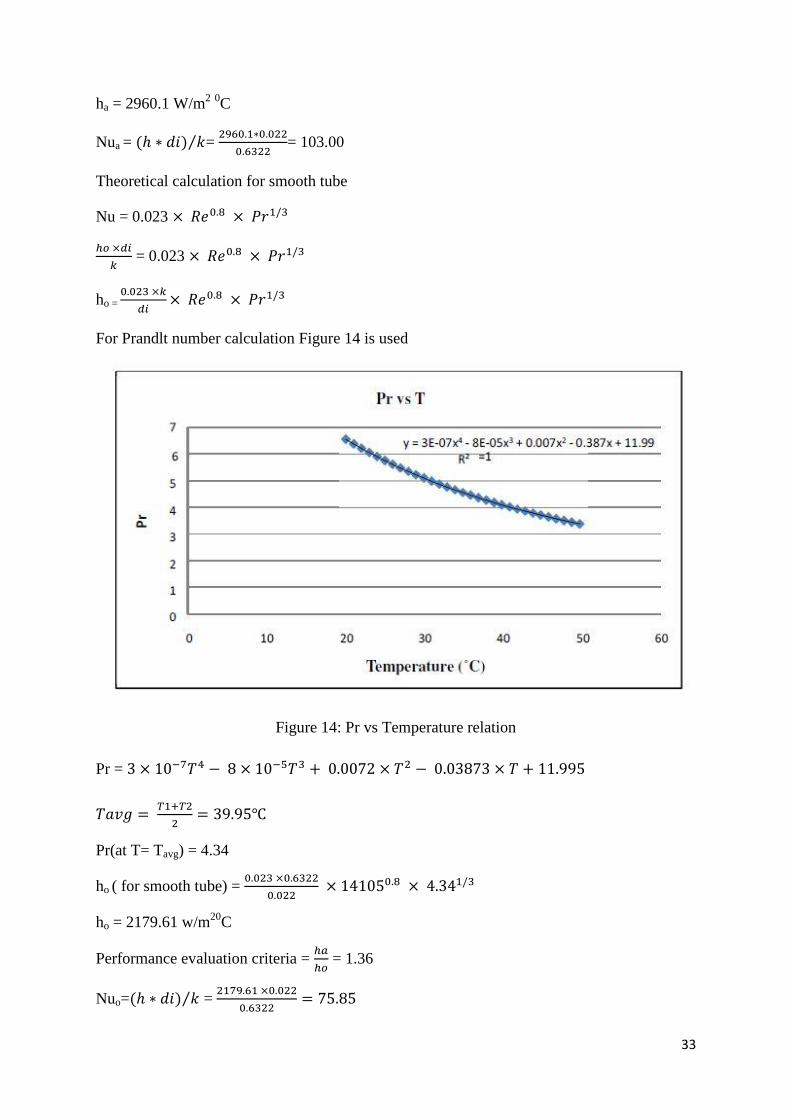
For Prandlt number calculation Figure 14 is used
Figure 14: Pr vs Temperature relation
Pr =
Pr(at T= Tavg) = 4.34
ho ( for smooth tube) =
ho = 2179.61 w/m20
C
Performance evaluation criteria =
= 1.36
Nuo= =

34
Chapter 5

35
RESULTS AND DISCUSSION
5.1 HEAT TRANSFER RESULTS FOR INSERT WITHOUT BAFFLES
Table A.2.1-A.2.5 gives the heat transfer results for smooth tube, 4 wire insert without any
baffle and with baffles(=24cm, 12cm, 6cm ) along with the performance evaluation criteria
for each of the readings. As shown in Figure 15 and Table 9, the difference between the
experimental values and the values calculated using the empirical equations is within 5%.
So the experimental setup can be considered to produce reliable heat transfer results.
Figure 15: Nusselt number comparison for smooth tube.
.

36
5.2 HEAT TRANSFER RESULTS FOR INSERT WITH BAFFLES
Figures below show the comparision of heat transfer results for smooth tube, 4 wire insert
without any baffle and with baffles at 24cm, 12cm and 6cm. Figure 16 shows the variation of
Nusselt number for smooth tube and 4 wire insert without baffles, against varying Reynolds
number.
Figure 16: Comparison of Nusselt number for smooth tube and 4 wire insert without baffles.
As seen from figure 16, the 4 wire insert without baffles can be represented by equation
. From Table 10 it can also be observed that the Nusselt number for 4
wire insert without baffles is 28-45% higher than that for equivalent smooth tube.

37
Figure 17 shows the variation of Nusselt number values for smooth tube and 4 wire insert
with baffles at 24cm. Equation can be used to represent 4 wire insert
with baffles at 24cm. From Figure 17 and Table 11 it can also be observed that the Nusselt
number for the insert is 33-55% higher than that for equivalent smooth tube.
Figure 17: Comparison of Nusselt number values for smooth tube and 4 wire insert with
baffles at 24cm.

38
Figure 18 shows the variation of Nusselt number values for smooth tube and 4 wire insert
with baffles at 12cm.
Figure 18: Comparison of Nusselt number values for smooth tube and 4 wire insert with
baffles at 12cm
From Figure 18 and Table 12 it can be seen that the Nusselt number for 4 wire insert with
baffle spacing 12cm is 39-90% higher than that of equivalent smooth tube. It can be
represented by the equation

39
Figure 19 shows the variation of Nusselt number values for smooth tube and 4 wire insert
with baffles at 6cm.
Figure 19: Comparison of Nusselt number values for smooth tube and 4 wire insert with
baffles at 6cm.
From figure 19 and table 13 it can be seen that the Nusselt number for 4 wire insert with
baffle spacing 6cm is 48-100% higher than that of equivalent smooth tube. It can be
represented by the equation

40
Figure 20 shows the variation of Nusselt number values for smooth tube and 4 wire insert
with and without baffles.
Figure 20: Comparison of Nusselt number for all configurations
As can be seen from the graph; as baffle spacing ß decreases a higher degree of turbulence is
created in the tube & hence the Nusselt number increases as the baffle spacing decreases.

41
In Figure 21, performance evaluation criteria R1 is plotted against Reynolds number for
smooth tube, 4 wire insert without any baffle and the 4 wire insert with baffles at 24cm, 12cm
and 6cm, where R1 is defined as the increase in the heat transfer rate for fixed geometry and
flow rate. From table 6, the overall range of R1 has been found to be 1.28-2.05, increasing in
the order of decreasing baffle spacing, the minimum being for the insert without baffles and
the maximum being for insert with baffle space 6cm. With this we can conclude that this is
the best arrangement out of all arrangements tested for this experiment.
Figure 21: Comparison of Performance Evaluation Criteria for all the inserts.
Figure 21 has been obtained by fitting a polynomial of degree 3 to the data points obtained
from all configurations.

42
EMPIRICAL RELATIONS DEVELOPED
From Figure 15-19 , the equations developed to represent the inserts have been summarized
in the table below.
Table 3: Summary of equations developed for all configurations of the insert.
In the above equations the effect of is included with the average value of Prandlt
number being 4.34.
S.no Configuration Equation Developed
1. Tube with 4 wire insert without baffles
2. Tube with 4 wire insert with baffles at 24cm
3. Tube with 4 wire insert with baffles at 12cm
4. Tube with 4 wire insert with baffles at 6cm

43
Chapter 6

44
CONCLUSION
The range of Nusselt number and performance evaluation criteria is given in the table below.
Table 4: Summary of the results.
S.no Insert
Nusselt
number
Performance Evaluation
Criteria
1 4 wire insert with no baffles 61-176 1.28 - 1.45
2 4 wire insert with baffles at 24cm 65-180 1.33 - 1.55
3 4 wire insert with baffles at 12 cm 80-187 1.39 - 1.90
4 4 wire insert with baffles at 6 cm 87-195 1.48 - 2.05
On the basis of performance evaluation criteria, it can be said that the 4 wire insert with
baffle space 6cm is the best among all the configurations used as it gives the highest value of
performance evaluation criteria value
It can also be observed that with decrease in baffle spacing ß, the Nusselt number increases. It
varies in the range of 61-195, the minimum being for insert without any baffles and
maximum being for insert with baffle space 6cm. But this improvement comes with an
increase in values of pressure drop as well. Hence it would not be reliable to judge an insert’s
compatibility on the basis of Nusselt number value alone.

45
SCOPE FOR FUTURE WORK
Further modification can be done taking this study as the basis. Some of the possible areas of
research may be:
1. Design of baffles can be changed to observe the effect they have on heat transfer
coefficient of the tube and thus its Nusselt number.
2. The distance between baffles can further be Decreased as reducing the baffle distance
gives good results
3. Different material for fabrication of baffles can be used.
4. Different number of wires can be used to alter the thickness of the main insert and
hence changes in the Nusselt number can be noted.

46
REFERENCES
1. B.Adrian and K. Allan D. Heat transfer enhancement. In Heat Transfer Handbook, Chapter
14, pg.1033, -1101, Wiley-interscience, 2003.
2. Bergles, A.E. ―Techniques to augment heat transfer.‖ In Handbook of Heat Transfer
Applications (Ed.W.M. Rosenhow), 1985, Ch.3 (McGraw-Hill, New York).
3. Bergles, A.E. and Blumenkrantz, A.R. ―Performance evaluation criteria for enhanced heat
transfer surfaces‖. Proc. Of 5th Int. Heat Conf., Tokyo, Vol 2, 239-243(1974)
4. A. Dewan, P. Mahanta, K Sumithraju, P. Suresh kumar ―Review of passive heat transfer
augmentation techniques‖. Proc. Institution of Mechanical Engineers Vol. 218
Part A (2004): Journal of Power and Energy.
5. Whitham, J. M. The effects of retarders in fire tubes of steam boilers. Street Railway.
1896, 12(6), 374.
6. Saha, S. K. and Dutta, A. ―Thermo-hydraulic study of laminar swirl flow through a
circular tube fitted with twisted tapes.‖ Trans. ASME, J. Heat Transfer, 2001, 123, 417–421.
7. Date, A. W. and Singham, J. R. Numerical prediction of friction and heat transfer
characteristics of fully developed laminar flow in tubes containing twisted tapes.
Trans. ASME, J. Heat Transfer, 1972, 17, 72.
8. Hong, S. W. and Bergles, A. E. Augmentation of laminar flow heat transfer in tubes by
means of twisted-tape inserts.Trans. ASME J. Heat Transfer, 1976, 98, 251–256.
9. Tariq, A., Kant, K. and Panigrahi, P. K. Heat transfer enhancement using an internally
threaded tube. In Proceedings of 4th ISHMT–ASME Heat and Mass Transfer
Conference, India, 2000, pp. 277–281 (Tata McGraw-Hill, New Delhi).
10. Manglik, R. M. and Bergles, A. E. ―Heat transfer and pressure drop correlations for
twisted tape insert in isothermal tubes.‖ Part 1: laminar flows. Trans. ASME, J. Heat
Transfer, 1993, 116, 881–889.
11. Saha, S. K., Dutta, A. and Dhal, S. K. Friction and heat transfer characteristics of laminar
swirl flow through a circular tube fitted with regularly spaced twisted-tape elements. Int.J.
Heat and Mass Transfer, 2001, 44, 4211–4223
12. Lokanath, M. S. and Misal, R. D. An experimental study on the performance of plate heat
exchanger and an augmented shell and tube heat exchanger for different types of fluids for
marine applications. In Proceedings of 5th ISHMT– ASME Heat and Mass
Transfer Conference, India, 2002, pp. 863–868 (Tata McGraw-Hill, New Delhi).

47
13. Lokanath, M. S. ―Performance evaluation of full length and half length twisted tape
inserts on laminar flow heat transfer in tubes‖. In Proceedings of 3rd ISHMT–ASME
Heat and Mass Transfer Conference, India, 1997, pp. 319–324 (Tata McGraw-Hill,
New Delhi).
14. Al-Fahed, S., Chamra, L. M. and Chakroun, W. Pressure drop and heat transfer
comparison for both micro-fin tube and twisted-tape inserts in laminar flow.
Experimental Thermal and Fluid Sci., 1999, 18, 323–333.
15. Q. Liao, M.D. Xin ―Augmentation of convective heat transfer inside tubes with
threedimensional internal extended surfaces and twisted-tape inserts’ Chemical Engineering
Journal 78 (2000).
16. Ujhidy et. al, Fluid flow in tubes with helical elements, Chemical Engineering and
Processing 42 (2003), pp. 1–7.
17. Suresh Kumar, P., Mahanta, P. and Dewan, A. Study of laminar flow in a large diameter
annulus with twisted tape inserts. In Proceedings of 2nd International
Conference on Heat Transfer, Fluid Mechanics, and Thermodynamics, Victoria Falls,
Zambia, 2003, paper KP3.
18. Saha, S. K. and Chakraborty, D. ―Heat transfer and pressure drop characteristics of
laminar flow through a circular tube fitted with regularly spaced twisted tape elements with
multiple twists‖. In Proceedings of 3rd ISHMT–ASME Heat and Mass Transfer
Conference, India, 1997, pp. 313–318 (Tata McGraw-Hill, New Delhi).
19. Sivashanmugam, P. and Suresh, S. ―Experimental studies on heat transfer and friction
factor characteristics of turbulent flow through a circular tube fitted with regularly spaced
helical screw tape inserts‖, Experimental Thermal and Fluid Science 31 (2007).301-308.
20. Agarwal, S. K. and Raja Rao, M. Heat transfer augmentation for flow of viscous liquid in
circular tubes using twisted tape inserts. Int. J. Heat Mass Transfer, 1996, 99, 3547–
3557.
21. Watcharin Noothong, Smith Eiamsa-ard and Pongjet Promvonge ―Effect of Twistedtape
Inserts on Heat Transfer in a Tube‖. The 2nd Joint International Conference on
―Sustainable Energy and Environment (SEE 2006)‖, 21-23 November 2006, Bangkok,
Thailand
22. Smith Eiamsa-ard, Chinaruk Thianpong, Petpices Eiamsa-ard, Pongjet Promvonge.
―Convective heat transfer in a circular tube with short-length twisted tape insert‖. Int.
communications in heat and mass transfer (2009).

48
APPENDIX
A.1: CALIBRATION RESULTS
A.1.1: ROTAMETER CALIBRATION
Table 5: Rotameter Calibration
Observation 1 Observation 2 Observation 3
Rotameter
reading
LPH
Mass
flow
rate
Kg/sec
Wt
kg
Time
sec
m
Kg/sec
Wt
kg
Time
sec
m
Kg/sec
Wt
kg
Time
sec
m
Kg/sec
Average
m
Kg/sec
350 0.0972 12.6 150 0.1284 11.2 138 0.081159 11.96 153 0.07817 0.0927
400 0.1111 12.4 125 0.0992 12.4 132 0.093939 11.16 121 0.092231 0.1081
500 0.1381 11.2 105 0.106667 12 111 0.108108 11.14 103 0.108155 0.1357
600 0.16667 12.45 92 0.135326 13.7 99 0.138384 12.3 92 0.133696 0.1622
700 0.1945 13.3 82 0.162195 11.8 72 0.163889 12.6 78 0.161538 0.1901
800 0.2223 12.25 66 0.185606 12.55 65 0.193077 11.6 62 0.187097 0.2205
900 0.2501 13.3 62 0.214516 11.65 52 0.224038 11.55 51 0.226471 0.2471
1000 0.2778 12.75 53 0.240566 12.05 48 0.251042 12.9 45 0.286667 0.2752
1100 0.3056 13.6 51 0.266667 11.7 42 0.278571 12.3 41 0.3 0.302
1200 0.3334 12.25 42 0.291667 12.4 40 0.31 12.1 43 0.281395 0.3319
1250 0.3473 12.5 39 0.320513 13.2 39 0.338462 12.7 40 0.3175 0.3431
A.1.2: RTD CALIBRATION
Table 6: Rtd Calibration
S.NO Temperature Readings
T1
Corrected
T1 T2
Corrected
T2 T3
Corrected
T3 T4
Corrected
T4
1 34.0 34.0 34.3 34.0 34.1 34.0 33.9 34.0
correction -0.3 -0.1 +0.1

49
A.2: HEAT TRANSFER RESULTS
A.2.1: STANDARDISATION OF SMOOTH TUBE (Nuo vs Re)
Table 7: Standardisation Of Smooth Tube (Nuo Vs Re)
S.no m T1 T2 T3 T4 LMTD Ui Re Nui
(exp) Nui
(theo) %diff R1=
1 0.093 36.1 40.8 52.7 50.9 13.29 564.98 6878 43.26 42.41 -1.9994 1.0999
2 0.108 36 40.9 53 51.3 13.64 651.81 8021 46.47 47.91 3.0002 0.9699
3 0.136 36.1 40.6 52.3 50.3 12.91 851.39 10069 56.95 57.53 1.0004 0.9899
4 0.162 36.2 39.9 52.6 50.7 14.05 805.61 12035 67.40 66.73 -1.0001 1.01
5 0.19 36.1 39.3 52.9 50.8 14.14 887.92 14105 79.95 75.84 -5.412 1.0541
6 0.221 36.2 39.3 52.7 50.5 13.85 1051.5 16361 87.06 85.36 -2 1.0199
7 0.247 34 37.2 52.4 49.8 15.5 1152.4 18335 97.76 95.53 -2.339 1.0233
8 0.275 33.5 36.3 52.5 49.8 16.25 1160.7 20419 107.91 104.87 -2.8973 1.0289
9 0.302 33.5 35.8 52.9 49.9 16.75 1190.8 22408 118.90 113.24 -5 1.05
10 0.332 32.9 35 52.9 49.7 17.34 1264.2 24626 127.04 123.90 -2.5296 1.0252
11 0.343 31.7 34.6 53 49.8 18.25 1419.3 25457 131.73 127.24 -3.5304 1.0353
A.2.2: Nu VS Re FOR 4 WIRE INSERT WITH NO BAFFLES
Table 8: Nu Vs Re For 4 Wire Insert With No Baffles
S.no m T1 T2 T3 T4 LMTD Ui Re Nua Nuo R1=
1 0.0927 35.4 41.3 53.8 51.7 14.32 645.34 6878 61.50 43.26 1.45
2 0.1081 36 40.5 53.2 51.1 13.87 640.99 8021 66.49 46.47 1.3877
3 0.1357 36.8 40 53.6 51.4 14.09 648.08 10069 75.89 56.95 1.3191
4 0.1622 35.6 39.9 53 50.9 14.17 912.9 12035 90.81 67.40 1.3608
5 0.1901 35.8 39.3 52.6 51.1 14.28 829.44 14105 101.80 79.95 1.3422
6 0.2205 36 39.2 53.3 50.7 14.4 1106.72 16361 113.65 87.069 1.3314
7 0.2471 35.9 38.9 52.1 49.8 13.55 1204.41 18335 123.84 97.764 1.2964
8 0.2752 36.1 38.9 52.1 49.8 13.45 1300.09 20419 133.85 107.91 1.2763
9 0.302 36.4 39.1 52.5 50.2 13.6 1383.57 22408 160.28 118.90 1.4154
10 0.3319 36.9 40.1 52 49.8 12.39 1802.57 24626 163.29 127.04 1.3179
11 0.3431 36.5 38.9 52.6 50.8 13.99 1283.56 25457 176.36 131.74 1.386

50
A.2.3: Nu VS Re FOR 4 WIRE INSERT WITH ß= 24CM
Table 9: Nu Vs Re For 4 Wire Insert With ß= 24cm
S.no m T1 T2 T3 T4 LMTD Ui Re Nua Nuo R1=
1 0.0927 39 44.4 53.5 51.7 10.8 770.11 6878 65.66 43.26 1.5481
2 0.1081 39 43.9 53.1 51.4 10.72 829.35 8021 73.30 46.47 1.5299
3 0.1357 37.9 42.2 52.5 50.5 11.41 933.68 10069 80.20 56.95 1.3941
4 0.1622 38.1 42.3 52.7 50.7 11.46 1093.5 12035 97.18 67.40 1.4562
5 0.1901 38.2 41.7 52.8 50.8 11.83 1101.3 14105 103.00 79.95 1.3581
6 0.2205 38.1 41.1 52.6 50.3 11.85 1228.9 16361 122.65 87.069 1.4368
7 0.2471 38.3 40.3 52.9 50.6 11.95 1365.7 18335 133.63 97.764 1.3988
8 0.2752 38.5 41.1 52.5 51.2 12.04 1110.8 20419 146.11 107.91 1.3932
9 0.302 38.6 41 52.2 49.7 11.15 1653.8 22408 163.75 118.90 1.446
10 0.3319 38.7 41.3 53 50.5 11.75 1810.4 24626 165.39 127.04 1.3348
11 0.3431 38.5 41.1 52.4 50.2 11.5 1784.6 25457 179.99 131.74 1.4145
A.2.4: Nu VS Re FOR 4 WIRE INSERT WITH ß= 12CM
Table 10: Nu Vs Re For 4 Wire Insert With ß= 12cm
S.no m T1 T2 T3 T4 LMTD Ui Re Nua Nuo R1=
1 0.0927 35 41.7 52.6 46.6 11.25 904.05 6878 80.58 43.26 1.8999
2 0.1081 35.6 40.9 53.1 48.4 12.5 1077.7 8021 82.27 46.47 1.7171
3 0.1357 36.4 40.4 53 49.6 12.9 1150.5 10069 86.82 56.95 1.509
4 0.1622 35.2 40.3 53.9 49.4 13.9 1396 12035 102.76 67.40 1.5398
5 0.1901 35.4 39.7 52.7 49 13.3 1424.9 14105 123.70 79.95 1.631
6 0.2205 35.6 39.6 52.3 48.9 13 1564.1 16361 126.23 87.069 1.4788
7 0.2471 35.7 39.1 52.8 50 14 1617.2 18335 146.35 97.764 1.5321
8 0.2752 35.9 39.1 53.1 50.5 14.3 1694.7 20419 158.12 107.91 1.5077
9 0.302 36.2 39.3 52.9 50.4 13.9 1776.1 22408 169.07 118.90 1.493
10 0.3319 36.7 40.3 53 50 13 1902.7 24626 172.60 127.04 1.393
11 0.3431 36.3 38.7 53.1 51.8 15.2 2100.6 25457 186.46 131.74 1.4654

51
A.2.5: Nu VS Re FOR 4 WIRE INSERT WITH ß= 6CM
Table 11: Nu Vs Re For 4 Wire Insert With ß= 6cm
S.no m T1 T2 T3 T4 LMTD Ui Re Nua Nuo R1=
1 0.0927 38.5 44.9 52 46.4 7.5 1848.3 6878 87.15 43.26 2.05482
2 0.1081 38.5 44.3 52.7 47.7 8.8 1653.2 8021 90.70 46.47 1.89291
3 0.1357 37.4 42.7 52.3 47.8 9.495 1658 10069 98.32 56.95 1.70902
4 0.1622 37.6 42.8 53 48.6 10.6 1831.4 12035 119.73 67.40 1.79413
5 0.1901 37.7 42.2 53.6 49.9 11.8 1646.9 14105 130.42 79.95 1.71957
6 0.2205 37.6 41.6 53.4 50.2 12.2 1622.1 16361 134.95 87.069 1.581
7 0.2471 37.7 40.8 52.7 50.4 12.3 1352.3 18335 157.42 97.764 1.6479
8 0.2752 38 40.6 52.5 50.7 12.3 1227.2 20419 172.58 107.91 1.64564
9 0.302 38.1 41.5 52.9 50.3 11.8 1914.4 22408 184.83 118.90 1.63221
10 0.3319 38.2 41.8 53 50.2 11.6 2282.9 24626 183.86 127.04 1.48388
11 0.3431 38 41.6 53.1 50.3 11.9 2300.3 25457 194.82 131.74 1.53105