experimental results from pitz@zeuthen how to reach … · emittance vs charge ~ linear. slice...
TRANSCRIPT

• experimental results fromATF@BNL, SDL@BNL,GTF@SLAC, SHI+FESTA@Japan, A0@FNAL, ELBE@Rossendorf
• experimental results from PITZ@Zeuthen
• How to reach the beam quality required for the XFEL ?
Frank Stephan (DESY Zeuthen),TESLA meeting, Zeuthen, January 2004

Projected Emittance Measurements at ATF@BNLparameters:* 0.5 nC* 110 MV/m at gun* beam energy: 60 MeVmethode:* fitting Twiss parameters to 4 subsequent beam size measurements* transport optics adjusted to maximize beam size at BPM locations
fit result:n = 0.8 µm for 0.5 nC, accuracy: better than 15%
V. Yakimenko et. al.,FEL 01
path to small emittance:check resolution limit of BPM, stability of laser and RF, BBA of beam optical elements, improve gun gradient and QE, optimize transverse laser shape and emission phase, tune beam with SASE gain at VISA

Transverse Laser Shape Studies from ATF@BNLcylindical symmetric non-cylindical symmetric
F. Zhou et. al., EPAC 02
parameters:
• 0.46 – 0. 48 nC
• phase: 30º from zero crossing
• emittance measured at 40 MeV via quad scan
additional study:emittance vs
charge ~ linear

Slice Emittance Measurements from SDL@BNLsetup:
Courtesy of W. Graves
parameters:
• 200 pC
• 75 MeV
• laser: 2.4 ps FWHM
• slice width ~400 fs
t
y
14 16 18 20 22 24 26160180200220240260280300320340360
sign
al (a
rbun
its)
streak delay (picoseconds)

Slice Emittance Measurements from GTF@SLAC
setup:
D. H. Dowell et. al., LCLS-TN-03-2 (corr.)
parameters:
• 300 pC
• laser: 1.8 ps FWHM2 mm diameter on cathode
• phase: 30º from zero crossing
• slice width 550-750 fs
• beam size: signal cut at 5% of max.
head tail
Energy/Time
Spec
trom
eter
Im
age
head tail
Energy/Time
Spec
trom
eter
Im
age
0
20
40
60
80
100
-4 -2 0 2 4Time (ps)
Curre
nt (A
)0.0
1.0
2.0
3.0
4.0
5.0
-4.0 -2.0 0.0 2.0 4.0Time (ps)
�n
( �m
)
Bsol = 1.982 kGBsol = 1.967 kGBsol = 1.937 kG
projectedemittance

Frank Stephan TESLA meeting, Zeuthen, Jan. 2004 6
Projected Emittance vs Charge from GTF@SLAC
Courtesy ofJ. Schmerge

Frank Stephan TESLA meeting, Zeuthen, Jan. 2004 7
• 1.6 cell S-band gun (� 4 MeV) + 70 cm SW linac (� 14 MeV)
• Ti:Saphire laser system (� 50 fs long pulses at 800 nm) +pulse shaping (e.g. gratings + liquid crystal spatial light modulator)
• temporal shape of laser pulses: (x-ray streak camera, resolution: ~2 ps)
• transverse laser distributions: (cathode)
WR on Emittance from SHI+FESTA@Japan
F. Sakai et. al., ICFA workshop 2002, SPring8
rise/decay time: 1.5 ps, limited by streak camera
„Gaussian“
„Square“

Frank Stephan TESLA meeting, Zeuthen, Jan. 2004 8
1.2
�n � 1.2 � mm mradFor 1 nC:
Methode: quad scan @ 14 MeV, gaussian fit to background subtracted signal frames
F. Sakai et. al., ICFA workshop 2002, SPring8

Measurements at FNPL(A0)@FNALflat beam production:
after solenoid field: after skew quads:
proof-of-principle experiment done, measured:� now working for ratio > 100
Courtesy ofPh. Piot
et. al.
also working on e.g. plasma-wakefield acc., laser-based acceleration (needs E upgrade)
NEXT: energy upgrade + 3.9GHz accelerating structure+ 3.9 GHz deflecting cavity
towards polarized electrons: vacuum !! �crogenic operated 1 ½ cell Cu gun

Frank Stephan TESLA meeting, Zeuthen, Jan. 2004 10
Cavity
Cooling insert
Helium tankChoke filter
2.5 mm mrad
0.5 mm mrad
E = 9.5 MeV
I = 1 mA CW
1 nC77 pC
1.3 GHz, 10 kWhalf cell & 3 TESLA cells Ez,max= 33 MV/m (1/2 cell)
= 50 MV/m (T cells)
Cathode
• first operation of a SRF photo gun (1/2 cell) in 2002:� measured current, energy + emittance @ ~1 pC
• start of the 3+1/2 cell project in 2004:
SC RF Gun Development at ELBE@Rossendorf
Courtesy of J. Teichert
Collaboration: BESSY, MBI, TJNAF, Univerity of Peking, BINP, DESY, ACCEL, TU Dresden
(without th. emit.)

Frank Stephan TESLA meeting, Zeuthen, Jan. 2004 11
Experimental Results from PITZ@Zeuthen
BESSY Berlin, DESY (HH + Z),INFN Frascati, INFN Milano,INR Troitsk, INRNE Sofia,LAL Orsay, MBI Berlin,TU Darmstadt, TU Eindhoven,U Hamburg, YERPHI Yerevan
Collaboration:
(1.3 GHz)

Frank Stephan TESLA meeting, Zeuthen, Jan. 2004 12
The Laser System at PITZ, ©MBI Berlin
diode-pumpedNd:YLF preamplifier
Pulse shaper(T = 5%)
Diode-pumpedNd:YLF oscillator
Emicro = 16 �JP = 16 W
AOM
fround trip = 27 MHz
EOMAOM
Faraday
pulsepicker1 MHz
pulsepicker
2-stage flashlamp-pumpedNd:YLF booster amplifier
fastcurrentcontrol
shot-to-shotoptimizer
2-stage diode-pumpedNd:YLF amplifier
fastcurrentcontrol
fourthharm.
Emicro = 200 �JP = 200 W
tophotocathode
20 ps flat-top4 ps edges
Emicro = 30 �JEburst = 24 mJUV (266 nm)2
1047 nm

-200
20406080
100120
40 50 60 70 80 90 100t / ps
a.u.
Measured
Flat Top Fit
Longitudinal and Transverse Laser Profiles
round diaphragms in the laser room (~ 20 m from the cathode) are imaged on the cathode
longitudinal (measured at 524 nm)
FWHM � 18-23 psrise/fall ~ 5-7 ps
transverse (measured in UV at virtual cathode)
y
x
variable transverse size:
standard parameters

Longitudinal Momentum of the Electron Beam Mean momentum vs RF phase
�0, degRMS momentum spread vs RF phase
�0, deg
Maximum mean momentum 4.72 MeV/cMinimum rms momentum spread 33 keV/c

Electron Beam Longitudinal ProfileCherenkov radiation
use of aerogel: SiO2 ,
refractive index ≈ 1.03
Bunch length (mm) in RMS 90 %:
�0, deg
Minimum bunch length: FWHM = (21.04 ± 0.45stat ± 4.14syst) ps
= (6.31 ± 0.14stat ± 1.24syst) mm

size of the beamlet is measured for three slit positions:
� �1,0,1
7.0 22
��
���
nnYy screen
yscreen
n �
Transverse Beam Emittance Measurement
Beam spot at screen 2single slitposition
Beamlets at screen 3
Single Slit Scan Technique

Frank Stephan TESLA meeting, Zeuthen, Jan. 2004 17
laser diaphragm diameter D = 1.0 mm (not final optimum)
emittance vs. charge, Imain = focus+5A
0.01.02.03.04.05.06.07.08.09.0
10.0
0.01 0.10 1.00 10.00
emitt_X 0degemitt_Y 0degemitt_X -5degemitt_Y -5deg
Transverse Emittance vs Bunch Charge
Q (nC)
εn(π
mm
mra
d)
εn ~ Q

Frank Stephan TESLA meeting, Zeuthen, Jan. 2004 18
vacuum mirror
steerer A
Steps to improve Beam Emittance
improvement: > 0.5 π mm mrad
1 nC, D = 1.2 mm
• systematic experimental optimization: long. laser profile, trans.laser profile, 2D scan Imain and RF phase, Ibuck for fine tuning
• status in Sept. 2003: min. emittance ≈ 3 π mm mrad
• improvement: steer beam away from vacuum mirror

Frank Stephan TESLA meeting, Zeuthen, Jan. 2004 19
Parameters used for the simulation:
• charge = 1 nC
• longitudinal laser profile:
– flat top
– 20 ps FWHM
– 5 ps rise/fall time
• transverse laser profile
– homogeneous
– �x,y = 0.6 mm
• max. gradient at the cathode: 42 MV/m
ASTRA Simulation of Transverse Emittance
Frank Stephan TESLA meeting, Zeuthen, Jan. 2004 20
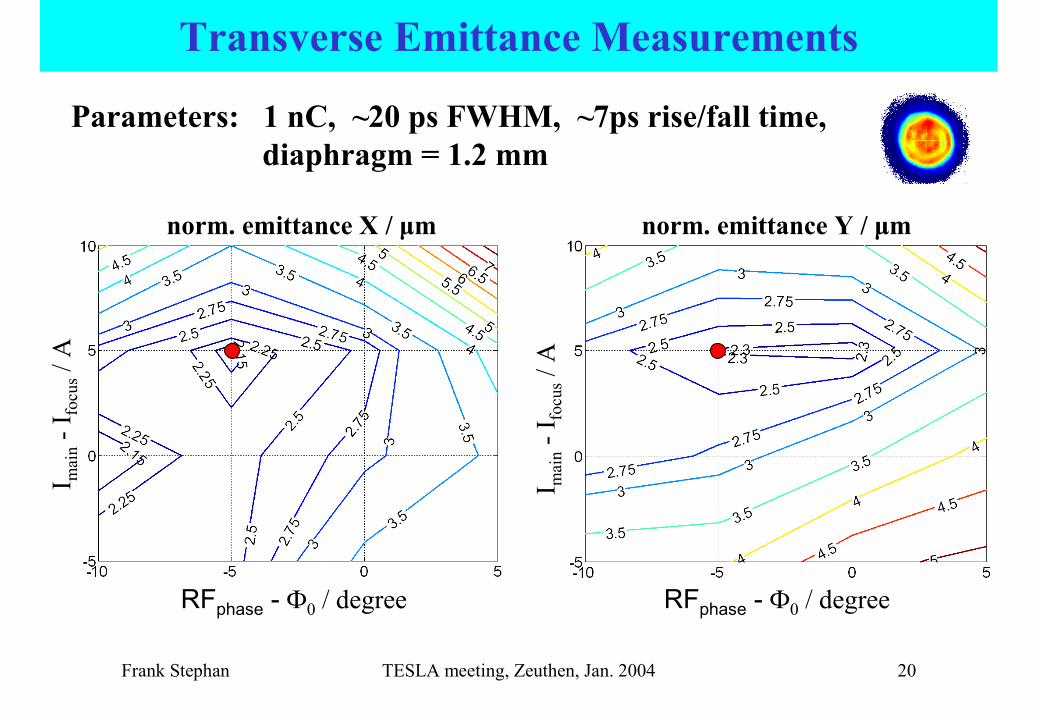
RFphase - �0 / degree RFphase - �0 / degree
I mai
n-I
focu
s/ A
I mai
n-I
focu
s/ A
norm. emittance X / µm norm. emittance Y / µm
Parameters: 1 nC, ~20 ps FWHM, ~7ps rise/fall time, diaphragm = 1.2 mm
Transverse Emittance Measurements
Frank Stephan TESLA meeting, Zeuthen, Jan. 2004 21
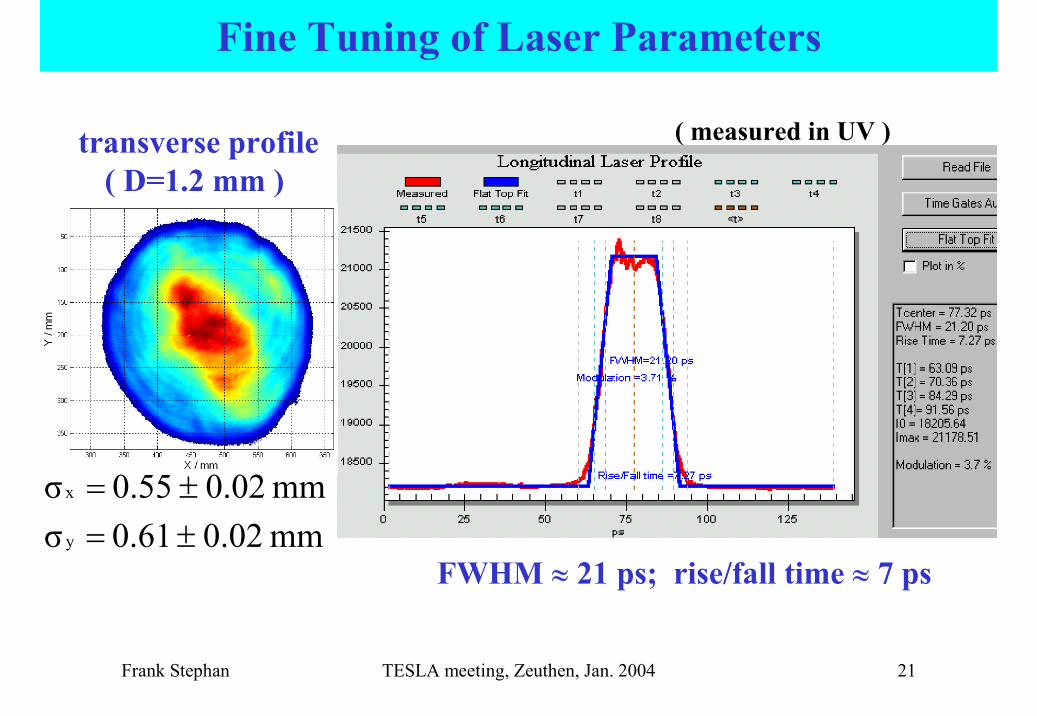
transverse profile ( D=1.2 mm )
FWHM � 21 ps; rise/fall time � 7 psmm 0.020.61σmm 0.020.55σ
y
x
��
��
Fine Tuning of Laser Parameters
( measured in UV )

Frank Stephan TESLA meeting, Zeuthen, Jan. 2004 22
Measured Transverse Emittance vs Bucking Solenoid
1 nC, -5deg, Imain = 305 A
1,01,21,41,61,82,02,22,42,62,83,0
0 10 20 30 40 50 60Ibuck / A
norm
aliz
ed e
mitt
ance
/ ��m
m m
rad
yx
yx
εεεε
1.7
1.5
WR=1.2
Requirement for the XFEL=0.9
Start-up Requirement for TTF2 =3
Start-up requirement of TTF2 is clearly fulfilled !

Frank Stephan TESLA meeting, Zeuthen, Jan. 2004 23
yxεε
Summary PITZ1
yε
• electron beam was characterized in a wide range of machineparameters (e. g. Q, Φ0, Imain, Ibuck, laser parameters)
• optimum settings @ 1 nC:= 1.7 � mm mrad= 1.5 � mm mrad have been reached with:
longitudinal laser shape:‘flat top’, FWHM � 21 ps, rise/fall time ≤ 7 ps
transverse laser profile:‘homogeneous’, �x,y � 0.55 - 0.6 mm
solenoid current:Imain � 305 A, Ibuck � 20-25 A → Bz = 0 at cathode
RF parameters:phase: � � �0 - 5� , gradient at cathode: ~ 42 MV/m
• cavity is now installed at TTF2

Frank Stephan TESLA meeting, Zeuthen, Jan. 2004 24
How to reach the beam quality required for XFEL
• upgrades with ~ 40 MV/m at the cathode:– really homegenous transverse laser profile:
� εn ~ 1.5 π mm mrad @ 1 nC (ongoing in 2004)
– improved longitudinal laser profile ( 2 ps rise/fall time):
� εn ~ 1.2 π mm mrad @ 1 nC (realisation in ~2004-2006)
• in addition, with 60 MV/m at the cathode:� εn ~ 0.9 π mm mrad @ 1 nC (started, ongoing in 2004,
depending on 10 MWklystron)
Goal: 0.9 π mm mrad from the injector for 10 Hz, 650 µs !!

Z0 - 50 cm Z0 - 25 cm Z0 Z0 + 25 cm Z0 + 50 cm
3 m
m
M2M1 M3 M4 MV
0 m 10 m5 m 15 m 20 m
f = 3000 mm
L out,2b L
in,1 L out,1b
f = 750 mmf = 750 mm
beam-shapingaperture
photo-cathode
<-------------- shaft --------------><----- laser table -----> <- wall -> <------ optical rail ------>
<------------- M = 7.3 ------------->
Gaussianinput beamFWHM = 2mm
± 0
cm+
50 c
m
- 50
cmL out,2a
f = -750
marginal rays
f = 750 f = -750
<--- M = 1:1 --->
L out,1a
f = -5000 d = 2 mm
pinhole
L in,2a L
in,2b
V - 50 cm
0
0.2
0.4
-0.2 -0.1 0 0.1 0.2
V - 25 cm
0
0.2
0.4
-0.2 -0.1 0 0.1 0.2
V - 00 cm
0.0
0.2
0.4
-0.2 -0.1 0 0.1 0.2
V + 25 cm
0
0.2
0.4
-0.2 -0.1 0 0.1 0.2
V + 50 cm
0
0.2
0.4
-0.2 -0.1 0 0.1 0.2
© I. Will (MBI), status: Draft
Proposed Setup for Laser Beam Line to Cathode

Frank Stephan TESLA meeting, Zeuthen, Jan. 2004 26
How to reach the beam quality required for XFEL
• upgrades with ~ 40 MV/m at the cathode:– really homegenous transverse laser profile:
� εn ~ 1.5 π mm mrad @ 1 nC (ongoing in 2004)
– improved longitudinal laser profile ( 2 ps rise/fall time):
� εn ~ 1.2 π mm mrad @ 1 nC (realisation in ~2004-2006)
• in addition, with 60 MV/m at the cathode:� εn ~ 0.9 π mm mrad @ 1 nC (started, ongoing in 2004,
depending on 10 MWklystron)
Goal: 0.9 π mm mrad from the injector for 10 Hz, 650 µs !!

Frank Stephan TESLA meeting, Zeuthen, Jan. 2004 27
Photo Cathode Laser Development for PITZ 2Strategy:
• further improve the Nd:YLF laser system
• two-channel mixingscheme
Goals: - stable and reliable laser system for long pulse trains
- micropulses temporal profile: 20 ps FWHM,rise and fall time ≤ 2 ps
- homogenous transverse intensity profile
- laser parameters widely variable
© I. Will, MBI

Frank Stephan TESLA meeting, Zeuthen, Jan. 2004 28
ASTRA Simulation of PITZ 2 (20ps FWHM, 2ps rise/fall time)
0
1
2
3
4
5
6
7
8
0 1 2 3 4 5 6 7 8 9 10z / m
Xrms(TESLA) / mm
EmX(TESLA) / um
Xrms(CDS14) / mm
EmX(CDS14) / um
Xrms(no booster) / mm
EmX(no booster) / um
matchingcondition
(M. Ferrario)
CDS booster
diagnostics section
�
�
�m
�m
�m
εn =1.2 µm
PITZ 2 setup:
Gun Booster
used gun gradient: 40 MV/m

Frank Stephan TESLA meeting, Zeuthen, Jan. 2004 29
How to reach the beam quality required for XFEL
• upgrades with ~ 40 MV/m at the cathode:– really homegenous transverse laser profile:
� εn ~ 1.5 π mm mrad @ 1 nC (ongoing in 2004)
– improved longitudinal laser profile ( 2 ps rise/fall time):
� εn ~ 1.2 π mm mrad @ 1 nC (realisation in ~2004-2006)
• in addition, with 60 MV/m at the cathode:� εn ~ 0.9 π mm mrad @ 1 nC (started, ongoing in 2004,
depending on 10 MWklystron)
Goal: 0.9 π mm mrad from the injector for 10 Hz, 650 µs !!

Frank Stephan TESLA meeting, Zeuthen, Jan. 2004 30
Transverse Beam Parameters for the XFEL Injector
proj. emittance
� 0.5 mrad mm
(no th. emittance)
11.5 MV/m 25.0 MV/m
13.9 MV/m
44°injecting phase
60 MV/mgun acc. gradient
20 ps, uniform
laserpulse length
0.74 mrad mm
assumed therm. emittance
0.75 mm, uniform
rms laser spot
Gun param.: